
LeviTouch - Shoes Gabor - Free user manual and instructions
Find the device manual for free LeviTouch Gabor in PDF.

| Product Type | Single-Arm Desktop Monitor Mount |
| Compatible Monitor Size | 15 to 27 inches (38.1 to 68.6 cm) |
| Maximum Load Capacity | 17.6 lb (8 kg) |
| VESA Compatibility | 75 x 75 mm, 100 x 100 mm |
| Tilt Range | -90° to +85° |
| Swivel Range | 180° |
| Rotation Range | 360° |
| Arm Pivot | 180° |
| Base Rotation | 135° |
| Maximum Arm Height | 17.7 in (45 cm) |
| Arm Height Adjustment Range | 14 in (35.6 cm) |
| Maximum Desktop Thickness | 3.5 in (9 cm) |
| Weight (without monitor) | 7 lb (3.2 kg) |
| Material | Rugged aluminum with gas spring |
| Connectors | USB 3.0 Standard-A, 1/8 in (3.5 mm) stereo male (x2) |
| Ports on Desktop | USB 3.0 Standard-A, 1/8 in (3.5 mm) stereo female (x2) |
| Cable Length | 4 ft (1.2 m) |
| Mounting Type | Clamp mount (low-profile for cubicles) |
| Cleaning Instructions | Use only a soft, dry cloth |
| Warranty | One-year limited warranty |
| Customer Support | www.madebygabor.com or 212-594-2353 |
| Included in Box | Mount head, arm, desk clamp, VESA plate, screws, hex keys, cable guides, desk plate, spacers |
Frequently Asked Questions - LeviTouch Gabor
User questions about LeviTouch Gabor
0 question about this device. Answer the ones you know or ask your own.
Ask a new question about this device
Download the instructions for your Shoes in PDF format for free! Find your manual LeviTouch - Gabor and take your electronic device back in hand. On this page are published all the documents necessary for the use of your device. LeviTouch by Gabor.
USER MANUAL LeviTouch Gabor
For 15 – 27 in. (38.1 – 68.6 cm) desktop computer monitors
User Manual
Thank you for choosing Gabor.
The Gabor Single-Arm Desktop Mount is a sturdy accessory that's capable of securely supporting monitors from 15-27 inches. The rugged aluminum build and durable gas spring mechanism will hold monitors up to 17.6 pounds. The mount consists of two articulating halves that give you maximum control over swivel, tilt, rotation, and height for precise monitor placement.
This desktop mount includes a low-profile clamp that will fit into a space with tight clearance, like a cubicle. Integrated USB 3.0 and audio cables connect with your computer to offer convenient desktop access to a USB port and headphone or microphone jacks.
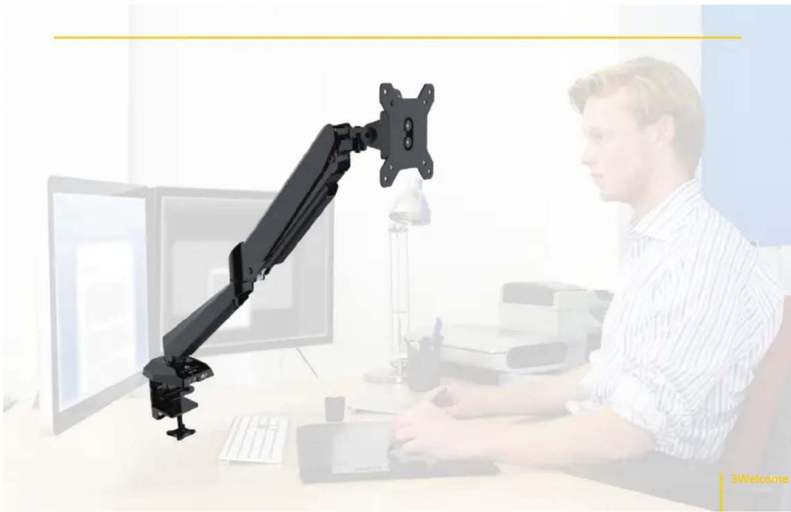
natural_image
Man working at a desk with a black robotic arm mounted on a computer monitor (no visible text or symbols)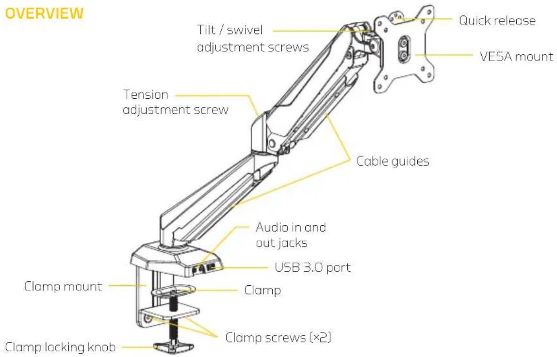
4 Overview
ALSO INCLUDED
Supplied Parts & Hardware
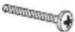
A M4×12 screws
B M4 x 30 screws
C M6×12 hex screws
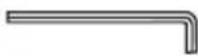
D 4 mm hex key
E M8×12 hex screws
F 5 mm hex key
G Spacers
H Desk plate
| M4M8M6 | Parts | ||
 |  |  |  |
 |  |  |  |
 |  |  |  |
 |  |  |
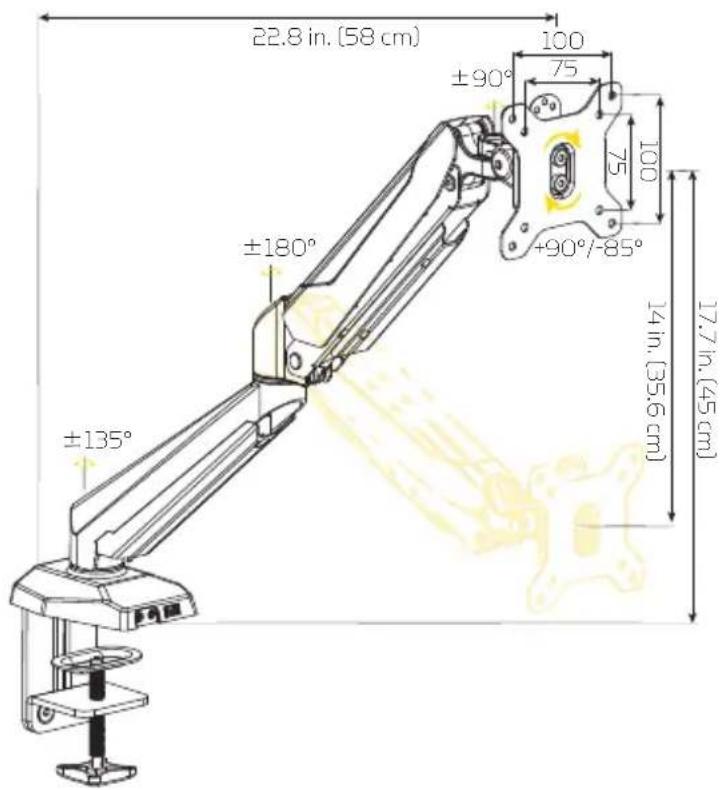
PRODUCT SPECIFICATIONS
Monitor display size: 15-27 in. (38.1-68.6 cm)
Maximum load capacity: 17.6 lb. (8 kg)
Maximum desktop thickness: 3.5 in. (9 cm)
VESA standards: 75 × 75, 100 × 100
Tilt: -90^ / + 85^
Swivel: 180°
Rotation: 360°
Arm pivot: 180°
Base rotation: 135°
Maximum arm height: 17.7 in. (45 cm)
Arm height adjustment: 14 in. (35.6 cm)
Connectors:
USB 3.0: Standard-A
Audio: 1/8 in. (3.5 mm) stereo male (×2)
Ports:
USB 3.0: Standard-A
Audio: 1/8 in. (3.5 mm) stereo female (×2)
Cable length: 4 ft. (1.2 m)
Weight (without monitor): 7 lb. (3.2 kg)
SAFETY WARNINGS
Please read and follow the instructions, and keep this manual in a safe place.
€lean this product with only a soft, dry cloth.
Keep this product away from children.
Make sure everything is secure before proceeding.
Make sure that this product is intact and that there are no missing parts.
To avoid damage to this product, be careful not to overtighten or improperly thread any of the threaded fittings.
Do not exceed the maximum load capacity.
Do not install this product on an unsteady structure or one that is prone to vibration, has a chance of being impacted, or is susceptible to other movements. Reinforce the structure as necessary before installing this product.
\$Mounting surfaces should be sturdy and flat. Do not install this product on a weak, uneven surface.
1All images are for illustrative purposes only.
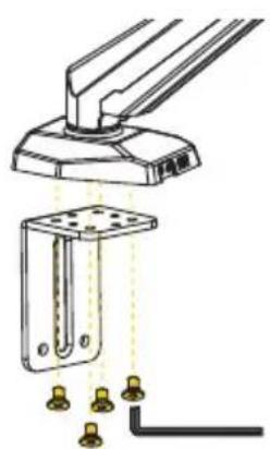
ASSEMBLY INSTRUCTIONS
-
Attach the desk clamp mount to the base with the M6 × 12 hex screws. Use the 4 mm hex key to tighten the screws until secure.
-
Align the desk plate with the provided holes, and press it into place over the screws.
-
Attach the clamp to the clamp mount with the M8 × 12 hex screws. Use the 5 mm hex key to tighten the screws until secure.
natural_image
Technical illustration of a mechanical assembly with mounting bracket and wiring (no text or symbols)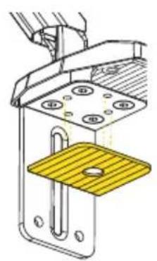
natural_image
Technical diagram of a mechanical assembly with a yellow plate and mounting holes (no text or symbols)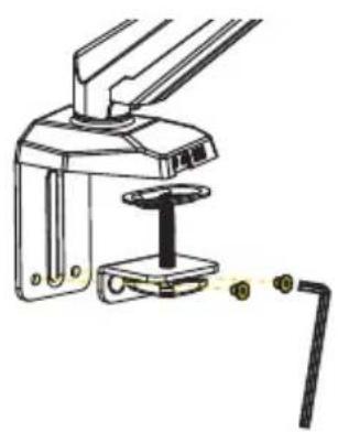
natural_image
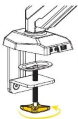
Mechanical device with attached lever and base mount (no visible text or symbols)Important! If installing the desktop mount in a cubicle or other space with limited clearance, slide the clamp mount between your desk and the partition first. Then attach the clamp to the clamp mount from underneath the desk.
- Tighten the clamp with the locking knob. For the most stability, the clamp should be parallel to the back edge of your desk.
Make sure the desktop mount doesn't wobble or shift and is securely clamped to the desk before proceeding.
natural_image
Diagram of a mechanical device with a yellow base and rotating arm (no text or symbols)Assembly Instructions
ATTACHING THE MONITOR
Flush Installation
- Carefully place your monitor facedown on a flat surface.
Tip: To avoid scratching the screen, place your monitor on a soft cloth such as a towel.
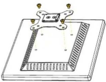
- Align the holes in the VESA mount with the corresponding mounting holes in your monitor.
Important: Make sure the raised edge of the VESA mount is at the top of your monitor.
- Insert the four M4×12 screws (the shorter of the Phillips screws) into the VESA mount, and use a Phillips screwdriver to fasten them until fully tightened.
natural_image
Technical line drawing of a mechanical component with mounting flanges and a rectangular base (no text or symbols)Recessed Installation
If the back of your monitor has a recessed area for the VESA mount, follow these steps:
- Carefully place your monitor facedown on a flat surface.
Tip: To avoid scratching the screen, place your monitor on a soft cloth such as a towel.
- Align the spacers with the mounting holes in your monitor.
- Align the the VESA mount holes with the spacers' mounting holes and monitor mounting holes.
Important: Make sure the raised edge of the VESA mount is at the top of your monitor.
- Insert the four M4 × 30 screws (the longer of the Phillips screws) into the VESA mount, and use a Phillips screwdriver to fasten them until fully tightened.

natural_image
Technical diagram of a mechanical assembly with mounting holes and a central component (no text or symbols)MOUNTING THE MONITOR
Once attached to the monitor, slide the VESA mount into the quick release until it locks into place.
To remove the monitor, pull the locking tab while lifting the monitor out of the quick release.

natural_image
Technical illustration of a mechanical assembly with a bracket and mounting bracket, showing a downward arrow indicating motion (no text or symbols present)12 Mounting the Monitor
ADJUSTING TENSION AND ARTICULATION
Important! The arm tension is preset for lighter monitors. To avoid damage, do not continue to loosen the screw if it's already loose.
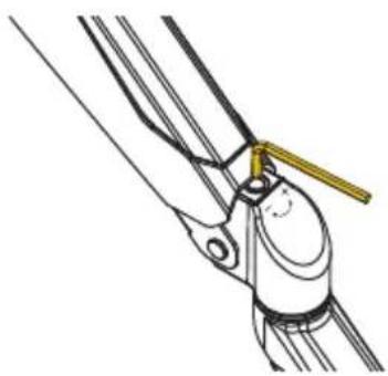
Arm Tension
To support your monitor's weight, you can adjust the tension of the mounting arm with the included 5 mm hex key.
The tension adjustment screw is located in the joint between the two arm segments.
- For heavier monitors, rotate the screw counterclockwise to increase tension.
- For lighter monitors, rotate the screw clockwise to reduce tension.
natural_image
Technical line drawing of a mechanical pulley system with a yellow-handled lever (no text or symbols)13Adjusting

Monitor Swivel and Tilt
Two adjustment screws at the top of the mounting arm regulate the monitor's (vertical) tilt and (horizontal) swivel action. Position your monitor as desired, and use the 5 mm hex key to tighten the screws (clockwise) to fix the monitor in its position.
If you want the monitor to swivel and tilt more freely, use the 5 mm hex key to loosen the screws (counterclockwise).
Important! Always hold your monitor with one hand when changing the tension of either screw.

natural_image
Technical line drawing of a mechanical clamp or bracket assembly with a yellow handle, labeled 'Swivel' below (no other text or symbols)
natural_image
Technical illustration of a mechanical clamp or tool with a yellow handle, labeled 'Tilt' below (no other text or symbols)14 Adjusting Tension and Articulation
ATTACHING THE CABLES TO YOUR COMPUTER
The Single-Arm Desktop Mount offers USB and audio connectivity with your computer, and it gives you a convenient USB 3.0 and audio ports on your desktop.
- Connect the USB plug to an available USB port on your computer or a USB hub.
- Connect the pink mini plug to the audio input (mic) jack on your computer.
- Connect the green mini plug to the output (headphone) jack on your computer.
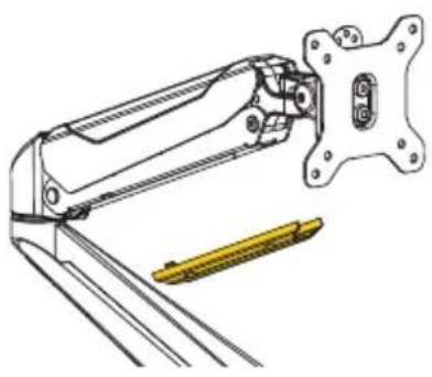
CABLE ORGANIZATION
The desktop mount comes with cable guides to organize the cables from your monitor and prevent clutter.
-
Remove the top cable guide by pressing in on the tabs and pulling the guide out of the arm.
-
Place the monitor cable inside the guide, and snap it back into place.
-
Remove the bottom cable guide by unscrewing the Phillips screw, and gently pull and slide it out of the guide slots.
-
Run the cable inside the guide. Then replace the guide and screw it in until tight.
natural_image
Technical line drawing of a mechanical clamp or lever assembly (no text or symbols)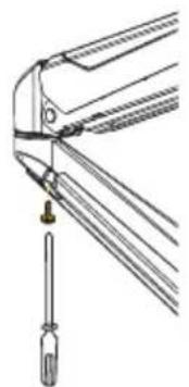
natural_image
Technical line drawing of a mechanical component with a screwdriver inserted (no text or symbols)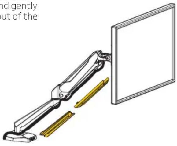
natural_image
Technical line drawing of a robotic arm with yellow guide rails extending to a blank panel (no text or symbols)TROUBLESHOOTING
| The desk is too thick for the clamp. | If your desktop is thicker than 3.5 in. (9 cm), follow these steps:1. Remove the clamp from the clamp mount.2. Completely remove the clamp screw and attachment.3. Turn the clamp upside down, and reattach the clamp screw and attachment. |
| The monitor won’t stay in one position. | Make sure your monitor weighs less than 17.6 lb. (8 kg).Adjust the arm tension by turning the adjustment screw counterclockwise to increase the tension. |
| The arm is clamped to the desk but is not steady. | Make sure the base is sitting flush against the desktop, and the clamp is fully tightened.Be sure to attach the desk plate over the attachment screws after attaching the clamp mount to the base.Make sure the long side of the clamp is parallel to the edge of the desk. |
CUSTOMER SUPPORT
For more information or to arrange service, visit www.madebygabor.com or call Customer Service at 212-594-2353.
Product warranty is provided by the Gradus Group. www.gradusgroup.com
Gabor is a registered trademark of the Gradus Group.
© 2016 Gradus Group LLC. All Rights Reserved.
GG2
ONE-YEAR LIMITED WARRANTY:
This Gabor product is warranted to the original purchaser to be free from defects in materials and workmanship under normal consumer use for a period of one (1) year from the original purchase date or thirty (30) days after replacement, whichever occurs later. The warranty provider's responsibility with respect to this limited warranty shall be limited solely to repair or replacement, at the provider's discretion, of any product that foils during normal use of this product in its intended manner and in its intended environment. Inoperability of the product or part(s) shall be determined by the warranty provider. If the product has been discontinued, the warranty provider reserves the right to replace it with a model of equivalent quality and function.
This warranty does not cover damage or defect caused by misuse, neglect, accident, alteration, abuse, improper installation or maintenance. EXCEPT AS PROVIDED HEREIN, THE WARRANTY PROVIDER MAKES NEITHER ANY EXPRESS WARRANTIES NOR ANY IMPLIED WARRANTIES, INCLUDING BUT NOT LIMITED TO ANY IMPLIED WARRANTY OF MERCHANTABILITY OR FITNESS FOR A PARTICULAR PURPOSE. This warranty provides you with specific legal rights, and you may also have additional rights that vary from state to state.
To obtain warranty coverage, contact the Gabor Customer Service Department to obtain a return merchandise authorization ("RMA") number, and return the defective product to Gabor along with the RMA number and proof of purchase. Shipment of the defective product is at the purchaser's own risk and expense.

Customer Support / Warranty

GABOR
A Gradus Group Brand


- Thank you for choosing Gabor.
- ALSO INCLUDED
- Supplied Parts & Hardware
- PRODUCT SPECIFICATIONS
- SAFETY WARNINGS
- ASSEMBLY INSTRUCTIONS
- ATTACHING THE MONITOR
- Flush Installation
- Recessed Installation
- MOUNTING THE MONITOR
- ADJUSTING TENSION AND ARTICULATION
- Arm Tension
- Monitor Swivel and Tilt
- ATTACHING THE CABLES TO YOUR COMPUTER
- CABLE ORGANIZATION
- CUSTOMER SUPPORT
- ONE-YEAR LIMITED WARRANTY:
Brand : Gabor
Model : LeviTouch
Category : Shoes