STO - Musical instrument Make Noise - Free user manual and instructions
Find the device manual for free STO Make Noise in PDF.

User questions about STO Make Noise
0 question about this device. Answer the ones you know or ask your own.
Ask a new question about this device
Download the instructions for your Musical instrument in PDF format for free! Find your manual STO - Make Noise and take your electronic device back in hand. On this page are published all the documents necessary for the use of your device. STO by Make Noise.
USER MANUAL STO Make Noise
FM, SYNC, and Variable Shape 8
Patch Ideas 9
Make Noise warrants this product to be free of defects in materials or construction for a period of one year from the date of purchase (proof of purchase/invoice required).
Malfunction resulting from wrong power supply voltages, backwards or reversed eurorack bus board cable connection, abuse of the product, removing knobs, changing face plates, or any other causes determined by Make Noise to be the fault of the user are not covered by this warranty, and normal service rates will apply.
During the warranty period, any defective products will be repaired or replaced, at the option of Make Noise, on a return-to-Make Noise basis with the customer paying the transit cost to Make Noise.
Make Noise implies and accepts no responsibility for harm to person or apparatus caused through operation of this product.
Please contact technical@makenoisemusic.com with any questions, Return To Manufacturer Authorization, or any needs & comments.
http://www.makenoisemusic.com
About This Manual:
Written by Tony Rolando
Edited by Walker Farrell
Illustrated by W.Lee Coleman
Beta Analyst: Walker Farrell, Joe Moresi
Test Subjects: Rob Lowe, Joseph Raglani
Electrocution hazard!
Always turn the Eurorack case off and unplug the power cord before plugging or un-plugging any Eurorack bus board connection cable.
Do not touch any electrical terminals when attaching any Eurorack bus board cable.
The Make Noise STO is an electronic music module requiring 40mA of +12VDC and 30 mA of -12VDC regulated voltages and a properly formatted distribution receptacle to operate. It must be properly installed into a Eurorack format modular synthesizer system case.
Go to http://www.makenoisemusic.com/ for examples of Eurorack Systems and Cases.
To install, find 8HP in your Eurorack synthesizer case, confirm proper installation of included eurorack bus board connector cable on backside of module (see picture below), plug the bus board connector cable into the Eurorack style bus board, minding the polarity so that the RED stripe on the cable is oriented to the NEGATIVE 12 Volt line on both the module and the bus board. On the Make Noise 6U or 3U Busboard, the negative 12 Volt line is indicated by the white stripe.

text_image
CNK 248 -12VPlease refer to your case manufacturers' specifications for location of the negative supply.
Overview:
The STO is a compact Voltage Controlled Oscillator designed for generating Sine waves, Variable wave-Shapes, Sub-Octaves, Oscillator SYNC and Linear FM in the analog domain. The Sub-Timbral Oscillator is the more subtle and melodic friend to the DPO's complex harmonic lattice. The STO yields harmonically rich textures through the use of Hard Sync, Linear FM and Variable Shape, but this VCO seems destined for melody.
The STO uses a Triangle Core and has outputs for Sine, SUB, and Variable Shape. The Sine is shaped from the Triangle using the same circuit used on the DPO. The Sub-Oscillator has its own gate input that lets the user turn it on/off at will. The Variable SHAPE ripples both Even and Odd Harmonics resulting subtle timbral shifts where the fundamental frequency is never masked. When combined with the Sub-Oscillator output (at the input of the MMG, for example) this makes for a rich, strong melodic voice.
The STO is a 100% analog musical instrument that is not suitable for laboratory use.
text_image
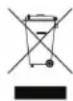
1 2 3 STO 4 5 FREQ 6' 7 LIN 8 SYNC 14 9 SHAPE 10 EXPA 1V/3CT S-GATE MAKE#EEL 11 12 13STO Panel Controls
- Variable Shape Waveform Output: 10Vpp
- Sub-Oscillator Output: 12Vpp
- Sine Waveform Output: 10Vpp
- Coarse Tune panel control: 9 octave range 8hz-4khz
- 1V/Octave Scale Trimmer (Calibration Use Only))
- Fine Tune panel control: +/-2.5 semi-tone range
- Linear FM Level: uni-polar attenuator for Linear FM input
- Linear FM Input: AC coupled, 10V range
- Variable Shape: Ripples Even and Odd harmonics. With nothing patched to Variable Shape CV Input, works as standard panel control. With Signal Patched to Variable Shape CV Input, works as an attenuatr for that signal.
- Variable Shape CV Input: Direct Coupled uni-polar control signal input, range 0V to +8V
- Expo Input: Exponential frequency control input. Bi-polar, 10V range
- 1V/Octave control Input: bi-polar pitch control, optimal range +/-5V
- S-Gate: Resets and turns Sub-Oscillator ON at Gate High, turns Off at Gate Low. Just about any signal that exceeds 1V work here.
14 SYNC: Resets Oscillator Core. Just about any 10Vpp audio rate signal works here.
There are three wave shapes that are derived from the oscillator core. These signals are all roughly 10V peak to peak and centered around 0V (bi-polar). The Sine wave is derived from the Triangle core of the oscillator and is provided as an output because it is great for blending with signals of greater harmonic content in order to strengthen the fundamental. The Sine shape has almost no harmonics, so it is also a good starting point for creating complex FM sounds because the sidebands introduced through FM are not be obscured by harmonics present in the signals utilized.
The Variable Shape is a unique waveform that is derived from the Sine. It is more harmonically rich then the Sine, but the fundamental frequency is still very strong. The Variable Shape carries the harmonics and sidebands introduced through Hard SYNC and FM with greater presence then the Sine shape. The end result is that the it will be more aggressive signal when using Hard SYNC or FM. The Variable Shape is also excellent for patching Subtractive synthesis sounds.
The Sub-Oscillator is a stepped rectangular shape derived from the comparator on the core of the STO are affected by SYNC patches as well as the EXPO, Linear FM, and 1V/Octave inputs and controls. The sound is similar to a Square wave, but it is one octave below the frequency of the Variable Shape and Sine waveforms making it very pleasant to combine with these signals. It thickens the sound and provides more harmonics for filters such as the MMG to work upon.
Control Inputs
There are several control inputs on the STO, all of which conform to the system wide standards. Just about any control or audio signals are effective in some way at these inputs.
The EXPO CV Input is similar to the 1V/Octave Input and in fact could be used for adding a second sequence (combining two sequences) or transposing a sequence patched to the 1V/Octave input. It is also highly useful for sweeping the Frequency of the STO to animate SYNC sounds or percussion patches. If wild textures are desired, the Expo input could be used to implement Exponential FM. When using for modulation be sure to patch a VCA such as the Optomix in series before the Expo CV Input as there is no attenuator associate with this input.
The 1V/Octave Input is typically used for controlling the Pitch of the STO from a sequencer, CV Keyboard or Midi to CV converter. It could also be used for all of the functions described above in the EXPO CV Input paragraph. When using for modulation, be sure to patch a VCA such as the Optomix in series before the EXPO CV Input, as there is no attenuator associate with this input.
The S-Gate input turns ON, OFF, and Resets the Sub-Oscillator. Just about any signal will work as a gate at this input. There are just two states, Sub On and Sub Off. Additionally, the Sub resets at the onset of the Gate High state (Sub On). This input is useful for animating the Sub-Oscillator, allowing it to have rythymic or percussive patterns not associate with the other outputs of the STO. If more narrow signal is used at this input, such as Saw from VCO A on the DPO, it is possible to create sync type sound in the Sub-Oscillator while the other outputs, Sine, and Variable Shape, are not affected.
The Linear FM input and associated attenuator is described below in the FM, Sync, and Variable Shape section. The SYNC input is described below in the FM, SYNC, and Variable Shape section. The Variable Shape input and associated attenuator is described below in the FM, SYNC, and Variable Shape section.
The STO is capable of generating harmonically rich waveforms. This is accomplished through the modulation of the Variable SHAPE, FM and Oscillator SYNC.
Linear and EXPO FM
Frequency Modulation super imposes the frequency of one oscillator upon another. The result is that the oscillator that is FM'd will carry the modulating oscillator's pitch information in the form of harmonics. Linear FM attempts to preserve the base frequency of the carrier oscillator allowing for harmonically rich waveforms to be generated while still being able to track the 1V/ Octave scale properly. The Linear FM input is AC coupled and has a Level control. As you increase the Level, the Amplitude of the signal Frequency Modulating the STO is increased and the resulting signals at all outputs of the STO will become increasingly more complex. At greater than 80% Level, the Linear FM bus goes into overdrive and the STO does not track accurately. Exponential FM is also possible with the STO by patching your modulating oscillator to the EXPO input. You will want to patch a VCA such as the OPTOMIX in series before the EXPO input on the STO to allow for Dynamic FM (voltage control over the FM Index). Exponential FM is much deeper and more complex then Linear FM; however, it severely changes the base frequency of the oscillator core and therefore the STO no longer tracks the 1V/ Octave scale properly. Exponential FM is highly useful when you require complex signals but you do not require proper tracking, for example, if you are programming percussion sounds.
Oscillator SYNC
SYNC patches introduce strong harmonics to all of the outputs on the STO. Sync uses a modulation method where the core of the STO is made to conform to that of an external VCO. Once SYNC'd the STO core restarts its period at each cycle of the external VCO signal, so they will have the same base frequency. Additional harmonics are achieved when the STO Frequency is Higher than that of the external VCO to which it is SYNC'd. In a SYNC patch, the timbre of the STO may be altered by varying it's frequency against that of the Master Frequency as set by the external VCO signal. Slow sweeping modulation of the STO core Frequency, such as an envelope or LFO patched to the EXPO Input, results in sweeping of harmonics. The best results are achieved by setting the external VCO to a base frequency of at least at least 100hz (around A2) and sweeping the STO Frequency from 100hz up!
SYNC has the advantage of tracking much more reliably then Linear FM; however, the sound is much more aggressive.
Variable SHAPE
This circuit is unique to the STO. It gently ripples both Even and Odd harmonics, while always maintaining a strong fundamental. At 0% the Variable Shape output is a Sine shape and at 100% it is a glitched triangle. Although it is well capable of audio rate modulation, it is best served by slower modulations such as logarithmic envelopes and LFOs from MATHS and/or FUNCTION and Smooth Random Voltages from the WOGGLEBUG. When modulated and combined with the Sub-Oscillator (at the inputs of the MMG or Optimix) this output creates a very strong voice for melodic sequencing.
The Sub Timbral Voice:
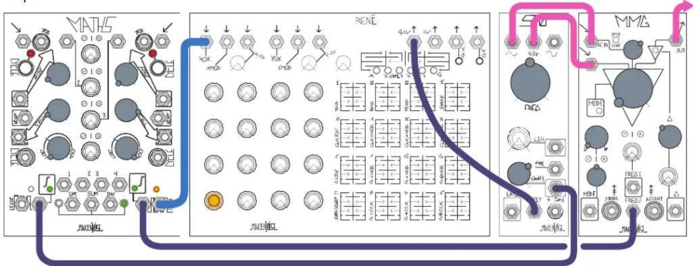
Patch Variable Shape output to AC input of MMG. Patch Sub-Osc output to DC input of MMG. Set STO Freq to around 12:00. Set MMG input attenuator to 1:00, MMG Freq full counter clockwise, MMG Q to 11:00 and Mode to LP. Patch slow LFO logarithmic from MATHS to Shape CV Input on STO and set Shape attenuator to about 60%. Patch sequencer or keyboard CV to 1V/Octave input on STO. Patch sequencer or keyboard gate to envelope generator such as MATHS or FUNCTION, programmed for fast Rise Time, Slow Fall Time and Exponential shape. Patch this exponential envelope to the Freq 2 CV Input on MMG. Monitor MMG Output.
flowchart
graph TD
    subgraph MATHS
        A["Switch 1"] --> B["Switch 2"]
        C["Switch 3"] --> D["Switch 4"]
        E["Switch 5"] --> F["Switch 6"]
        G["Switch 7"] --> H["Switch 8"]
        I["Switch 9"] --> J["Switch 10"]
        K["Switch 11"] --> L["Switch 12"]
        M["Switch 13"] --> N["Switch 14"]
        O["Switch 15"] --> P["Switch 16"]
        Q["Switch 17"] --> R["Switch 18"]
        S["Switch 19"] --> T["Switch 20"]
        U["Switch 21"] --> V["Switch 22"]
        W["Switch 23"] --> X["Switch 24"]
        Y["Switch 25"] --> Z["Switch 26"]
        AA["Switch 27"] --> AB["Switch 28"]
        AC["Switch 29"] --> AD["Switch 30"]
        AE["Switch 31"] --> AF["Switch 32"]
        AG["Switch 33"] --> AH["Switch 34"]
        AI["Switch 35"] --> AJ["Switch 36"]
        AK["Switch 37"] --> AL["Switch 38"]
        AM["Switch 39"] --> AN["Switch 40"]
        AO["Switch 41"] --> AP["Switch 42"]
        AQ["Switch 43"] --> AR["Switch 44"]
        AS["Switch 45"] --> AT["Switch 46"]
        AU["Switch 47"] --> AV["Switch 48"]
        AW["Switch 49"] --> AX["Switch 50"]
        AY["Switch 51"] --> AZ["Switch 52"]
        BA["Switch 53"] --> BB["Switch 54"]
        BC["Switch 55"] --> BD["Switch 56"]
        BE["Switch 57"] --> BF["Switch 58"]
        BG["Switch 59"] --> BH["Switch 60"]
        BI["Switch 61"] --> BJ["Switch 62"]
        BK["Switch 63"] --> BL["Switch 64"]
        BM["Switch 65"] --> BN["Switch 66"]
        BO["Switch 67"] --> BP["Switch 68"]
        BQ["Switch 69"] --> BR["Switch 70"]
        BS["Switch 71"] --> BT["Switch 72"]
        BU["Switch 73"] --> BV["Switch 74"]
        BW["Switch 75"] --> BX["Switch 76"]
        BY["Switch 77"] --> BZ["Switch 78"]
        CA["Switch 79"] --> CB["Switch 7A"]
        CC["Switch 80"] --> CD["Switch 81"]
        CE["Switch 81"] --> CF["Switch 82"]
        GD["Switch 83"] --> DH["Switch 84"]
        DI["Switch 85"] --> DJ["Switch 86"]
        DK["Switch 87"] --> DL["Switch 88"]
        DV["Switch 89"] --> DW["Switch 8A"]
        DX["Switch 90"] --> DXB["Switch 8B"]
        DXB --> DXC["Switch 8C"]
        DXC --> DXD["Switch 8D"]
        DXD --> DXE["Switch 8E"]
        DXE --> DXF["Switch 8F"]
        DXF --> DXG["Switch 8G"]
        DXG --> DXH["Switch 8H"]
        DXH --> DXI["Switch 8I"]
        DXI --> DXJ["Switch 8J"]
        DXJ --> DXK["Switch 8K"]
        DXK --> DXL["Switch 8L"]
        DXL --> DXM["Switch 8M"]
        DXM --> DXN["Switch 8N"]
        DXN --> DXO["Switch 8O"]
        DXO --> DXP["Switch 8P"]
        DXP --> DXQ["Switch 8Q"]
        DXQ --> DXR["Switch 8R"]
        DXR --> DXS["Switch 8S"]
        DXS --> DXT["Switch 8T"]
        DXT --> DXU["Switch 8U"]
        DXU --> DXV["Switch 8V"]
        DXV --> DXW["Switch 8W"]
        DXW --> DXX["Switch 8X"]
        DXX --> DXY["Switch 8Y"]
        DXY --> DXZ["Switch 8Z"]
        DXZ --> DXZA["Switch 8ZA"]
    end

    subgraph RENE
        B
        C
        D
        E
        F
        G
        H
        I
        J
    end

    subgraph MMA
        K
        L
        M
    end
Analog Bass Drum:
Patch Sine to Optomix CH. 1 Signal Input. Patch Gate to Linear FM Input and Optomix CH. 1 Strike Input. Set Linear FM amount to 12:00 and Frequency panel control to roughly 9:00. Set Optomix CH. 1 Damp and Control panel controls to full Counter Clock-Wise. Monitor Optomix CH. 1 Signal Output. Adjusting the Linear FM amount, Frequency setting, and Damp settings allow you to create many different Bass Drum sounds. Adding Expo FM from another VCO expands the possibilities.

flowchart
graph TD
    A["Audio"] --> B["STO"]
    B --> C["OPTOMIX"]
    C --> D["JAKEL"]
    style A fill:#f9f,stroke:#333
    style B fill:#ccf,stroke:#333
    style C fill:#cfc,stroke:#333
    style D fill:#fcc,stroke:#333
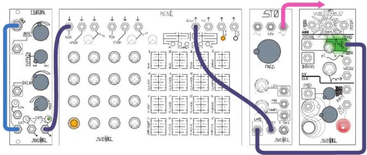
Transposition/Superimposition
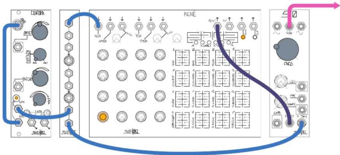
Patch a sequence such as from Rene to the STO's 1V/Oct input. Patch another sequence of a different speed, or control voltage from a keyboard, to the Expo input. The two sequences will be "added" together for transposition. Variations would include: clocking the transposing sequence at an odd division of the master clock, resulting in long periods between exact repetitions; deriving the transposing sequence from the master sequence via sample and hold; tuning a square wave LFO to +/- 1V for double octave leaps.
text_image
CONTINVR ONSET S/STAIN DECAP LDC CNR JWENDEL RENE 4.4V 5.0V 6.0V 7.0V 8.0V 9.0V 10.0V STO SJV FRA LUN SMH LXVD JWENDEL WINGZARUE AIRD EXTERIOR INTR SW ELK SPED JWENDELDual Sync
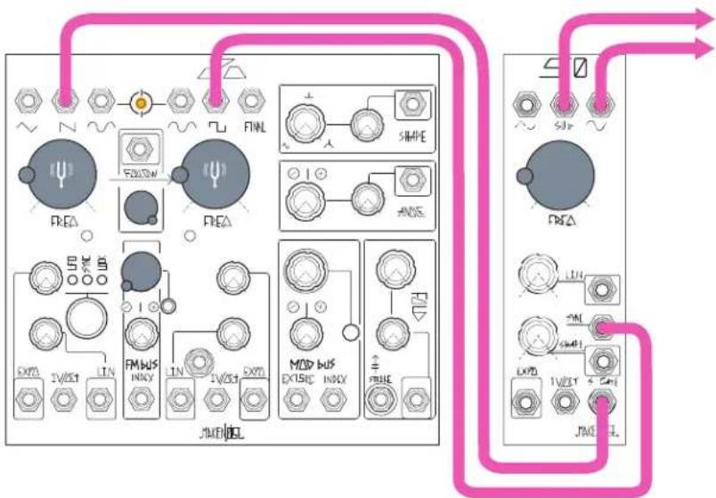
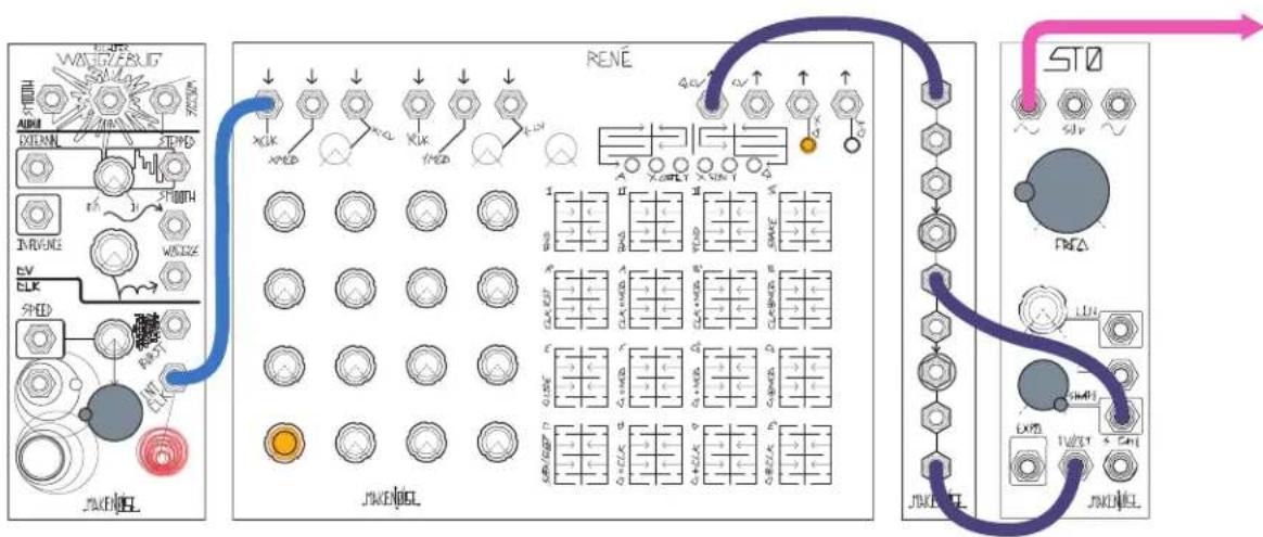
Patch an audio-rate square or sawtooth wave to the STO's S-Gate input, and another to the Sync input. The Sub output will be "pseudo-synced" to a different frequency from the Sine and Variable outs. If the Sync sources are related, such as from two sides of a DPO with Following engaged, so will be the STO's outputs.
flowchart
graph TD
    A["FEA"] --> B["FMEA"]
    B --> C["SIMPE"]
    C --> D["ANS"]
    D --> E["MOD BUS"]
    E --> F["JNENDEL"]
    F --> G["FXPD"]
    G --> H["LIN"]
    H --> I["FXPD"]
    I --> J["FXPD"]
    J --> K["LIN"]
    K --> L["FXPD"]
    L --> M["LIN"]
    M --> N["FXPD"]
    N --> O["LIN"]
    O --> P["FXPD"]
    P --> Q["LIN"]
    Q --> R["FXPD"]
    R --> S["LIN"]
    S --> T["FXPD"]
    T --> U["LIN"]
    U --> V["FXPD"]
    V --> W["LIN"]
    W --> X["FXPD"]
    X --> Y["LIN"]
    Y --> Z["FXPD"]
    Z --> AA["LIN"]
    AA --> AB["FXPD"]
    AB --> AC["LIN"]
    AC --> AD["FXPD"]
    AD --> AE["LIN"]
    AE --> AF["FXPD"]
    AF --> AG["LIN"]
    AG --> AH["FXPD"]
    AH --> AI["LIN"]
    AI --> AJ["FXPD"]
    AJ --> AK["LIN"]
    AK --> AL["FXPD"]
Key Tracking
Mult the control voltage in the 1V/Oct input to the Shape CV input and take output from Variable Wave Output. This results in higher pitches having more harmonic content, similar to keyboard tracking on a low-pass filter.
flowchart
graph TD
    A["ADC"] --> B["XCLK"]
    B --> C["XOUT"]
    C --> D["XCLK"]
    D --> E["XOUT"]
    E --> F["XCLK"]
    F --> G["XOUT"]
    G --> H["XCLK"]
    H --> I["XOUT"]
    I --> J["XCLK"]
    J --> K["XOUT"]
    K --> L["XCLK"]
    L --> M["XOUT"]
    M --> N["XCLK"]
    N --> O["XOUT"]
    O --> P["XCLK"]
    P --> Q["XOUT"]
    Q --> R["XCLK"]
    R --> S["XOUT"]
    S --> T["XCLK"]
    T --> U["XOUT"]
    U --> V["XCLK"]
    V --> W["XOUT"]
    W --> X["XCLK"]
    X --> Y["XOUT"]
    Y --> Z["XCLK"]
    Z --> AA["XOUT"]
    AA --> AB["XCLK"]
    AB --> AC["XOUT"]
    AC --> AD["XCLK"]
    AD --> AE["XOUT"]
    AE --> AF["XCLK"]
    AF --> AG["XOUT"]
    AG --> AH["XCLK"]
    AH --> AI["XOUT"]
    AI --> AJ["XCLK"]
    AJ --> AK["XOUT"]
Bassline
Patch a low-frequency square wave (or EOR/EOC gate from cycling MATHS, FUNCTION, or CONTOUR) to the S-Gate input, and take output from SUB Out. Mult the square wave to the Clock input of a sequencer and patch the sequencer's output to the STO 1V/Oct input. Adjust square wave pulse width (or MATHS/FUNCTION/CONTOUR's Rise/Fall times) to change the length of "notes."