Rosie - Uncategorized Make Noise - Free user manual and instructions
Find the device manual for free Rosie Make Noise in PDF.

| Product Type | Eurorack Audio Output Module |
| Brand | Make Noise |
| Model | Rosie |
| Width | 4 HP |
| Depth | 35 mm (approx.) |
| Weight | 120 g |
| Power Supply | +12V @ 50mA, -12V @ 30mA |
| Audio Inputs | 2x 1/8" TRS (stereo pair) |
| Audio Outputs | 1x 1/4" TRS (main line out), 1x 1/4" TRS (headphone) |
| Headphone Amplifier | Integrated, drives 32-600Ω headphones |
| Volume Control | Dedicated knob for headphone volume |
| Features | Stereo mixing, balanced output, mono compatibility |
| Mounting | Standard Eurorack rails, screws included |
| Operating Temperature | 0-50°C |
| Warranty | 2 years limited |
Frequently Asked Questions - Rosie Make Noise
User questions about Rosie Make Noise
0 question about this device. Answer the ones you know or ask your own.
Ask a new question about this device
Download the instructions for your Uncategorized in PDF format for free! Find your manual Rosie - Make Noise and take your electronic device back in hand. On this page are published all the documents necessary for the use of your device. Rosie by Make Noise.
USER MANUAL Rosie Make Noise
Make Noise warrants this product to be free of defects in materials or construction for a period of one year from the date of purchase (proof of purchase/invoice required).
Malfunction resulting from wrong power supply voltages, backwards or reversed eurorack bus board cable connection, abuse of the product, removing knobs, changing face plates, or any other causes determined by Make Noise to be the fault of the user are not covered by this warranty, and normal service rates will apply.
During the warranty period, any defective products will be repaired or replaced, at the option of Make Noise, on a return-to-Make Noise basis with the customer paying the transit cost to Make Noise.
Make Noise implies and accepts no responsibility for harm to person or apparatus caused through operation of this product.
Please contact technical@makenoisemusic.com with any questions, Return To Manufacturer Authorization, or any needs & comments.
http://www.makenoisemusic.com
About This Manual:
Written by Tony Rolando
Edited by Walker Farrell
Illustrated by W.Lee Coleman
Electrocution hazard!
Always turn the Eurorack case off and unplug the power cord before plugging or unplugging any Eurorack bus board connection cable.
Do not touch any electrical terminals when attaching any Eurorack bus board cable.
The Make Noise Rosie is an electronic music module requiring 45mA of +12VDC and 40 mA of -12VDC regulated voltages and a properly formatted distribution receptacle to operate. It must be properly installed into a Eurorack format modular synthesizer system case.
Go to http://www.makenoisemusic.com/ for examples of Eurorack Systems and Cases.
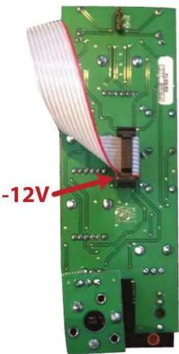
To install, find 8HP in your Eurorack synthesizer case, confirm proper installation of included eurorack bus board connector cable on backside of module (see picture below), plug the bus board connector cable into the Eurorack style bus board, minding the polarity so that the RED stripe on the cable is oriented to the negative 12 Volt line is indicated by the white stripe.
text_image
-12VPlease refer to your case manufacturers' specifications for location of the negative supply

text_image
RASIE 1 2 3 4 5 6 7 RETRN LEVEL SEND RETRN LEVEL 8 9 10 12 CUE LEVEL OUT DML LINE OUT [TKS] 13 11 MAKE NASERosie Panel Connections
- Channel A Signal Input: expects typical 10Vpp Audio signal from Modular System. AC coupled.
- Channel B Signal Input: expects typical 10Vpp Audio signal from Modular System. AC coupled.
- Channel A Level Indicator: LED lights to show strength of signal patched to Channel A input.
- Channel B Level Indicator: LED lights to show strength of signal patched to Channel B input.
- Crossfader: selects between Channel A and B or some combination of A and B to be sent to FX Send and Master Line Output.
- FX Send output: Mono 10Vpp Audio signal intended to be patched into the Modular System. Also possible to use with external Line Level devices if attenuation is applied.
- FX Return input(s): operates as Mono (use only top jack, marked M) or Stereo (use both Jacks marked M and ST) return for the FX Loop. Expects typical 10Vpp Audio signal from Modular System. AC coupled. May be used with Line Level devices as well (set Return Level to Max and adjust output volume at external device).
- Return Level: manually operated panel control to set the Level of the FX Loop Return in the Master Output. Range of 0% to 120%
- Master Level: Sets the volume of the Master Line Output.
- Overload indicator: OVL lights when signal Level is too high.
- Master Line Output: 1/4" TRS jack wired as Stereo output. Low output impedance (60 ohms) allows this output to drive Headphones as well as Line Level Inputs.
- CUE Level: Sets volume of the signal for CUE Headphones Output.
- CUE Output: TRS Mini-Jack wired as MONO. Low output impedance (30 ohms) allows this output to drive Headphones, as well as Line Level inputs.
Rosie is an output interfacing module with the added functionalities of a FX Loop, Crossfader, and Auto-Cue system. It features two Mono Inputs (Channel A and B) each with LED indication of signal strength, a crossfader to select between Channel A and B, a Mono FX Send with Stereo FX Return and Return Level control, a Master Level control with Limiting and overload indication, a Line Level 1/4" Stereo output and the Auto-CUE system with independent Level control and Headphone output. Both the CUE and Master Outputs use high quality Burr Brown line drivers capable of driving long cable runs out to the PA or a set of headphones.
The Rosie is designed to facilitate live performance on the modular synthesizer by allowing the artist to preview and modify portions of a patch using the Auto-CUE system, while the audience is listening to a different portion of the patch as selected by the crossfader. Additionally it allows for stereo processing of all sounds that are live in the PA using the the FX Loop. The Rosie is also suitable for headphone monitoring of the modular system for personal use and for interfacing the modular system to a recording environment. Because all signal levels are scaled within the Rosie, the user does not need to be concerned with interfacing the large signal levels from the modular system to the more typical Line Level inputs found on most audio gear.
It is designed to be installed in the bottom most row, at the right hand edge of system. This prevents physical interference from the bulky 1/4" cable.
The crossfader is the topmost knob on the Rosie. It allows for manual crossfading between Channel A and B. It works together with the FX Send (FX Loop) and Auto-CUE system. When the crossfader is set to be fully counter clockwise, Channel A is selected and the signal patched to Channel A signal input will be routed to the FX Send output and Master Line Output. The signal at the FX Send Output is at Unity (this means signal is same level as it was at the input, with respect to the crossfader setting). In most cases this will be around 10Vpp. The signal at the Master Line Output will be at Line Level (around 2Vpp with Max 3Vpp) and is determined by the setting of the Master Level panel control. This makes it easy to plug the modular synthesizer system into most other audio devices (mixers, amplifiers, recording interfaces and etc...). While Channel A is routed to the FX Send Output and Master Line Output, Channel B is routed to the CUE Headphone Output, the level of which is set by the CUE Level. This allows the user to monitor and preview Channel B while the audience is listening to Channel A. The CUE system is automatic. The user does not need to do anything for the CUE channel to change. When user sweeps crossfader from Full CCW to Full CW, Channel B is then be routed to the FX Send output and Master Line Output. The audience listens to Channel B. While Channel B is routed to the FX Send Output and Master Line Output, Channel A is routed to the CUE Headphone Output for user to preview. The CUE Headphone Output is designed to work well with Headphones, but it also drives just about any Line Level destination.
The FX Loop
The FX Send is same signal as the Master Line Output, but at the typical 10Vpp modular signal level. To use the FX Loop, patch the FX Send to the input of any processing module in the system (ECHOPHON or Erbe Verb for example). If the processing module has a Mix control, set it to be 100% WET (no dry/ unprocessed signal). Patch the output of the processing module to the FX Return input on the Rosie. Your FX loop could have multiple processing stages. The modules used for processing could be just about anything you'd like to use. Even filters, ring modulators and other processors are OK to use. Be careful that the Phase of the processor is not inverted, as it could result in phase errors that cause signal loss (which might be something fun to experiment with as well). It is important to set the Mix control to 100% Wet when possible, as the Dry Signal will already be routed to the Master Line Output on the Rosie.
The Return Level on the Rosie sets the amount of processed signal that is blended in with the dry/unprocessed signal. The Master Level control sets the overall volume of the signal at the Master Line Output. It is not possible to have a 100% WET mix using the Rosie FX Loop.
The Cue signal is not routed to the FX Send as you would not want audience to hear your CUE signal in the FX processing. However, as the cued signal is crossfaded into the Master Line Out, it is applied FX Send as well. This allows for some fantastic smearing of Channel A and B as you fade between the two channels.
For Voltage control over FX Loop, patch Send output to VCA before processing module. The VCA controls the Level/Amount of signal sent to FX processing Loop.
The Line Output level is clean up to about 75%, where it will start to overload and clip. The OVL (overload) indicator lights to indicate this clipping. The Line Output is a Tip Ring Sleeve jack the provides a Stereo output on a single jack. It is also OK to use this output as a Mono Output by using a Tip Sleeve jack. This output is capable of driving loads typical of Headphones, long cables runs to a mixer and just about any Line Level Input.
The Cue Output
Cue output is opposite of the Line Output. So when crossfader is set for CH. A, the CUE automatically cues up Ch. B so you could monitor another part of the patch to prepare to fade into the live Line output. In other words, plug headphones into CUE and plug the Line Output to your PA system.
The cue signal is not routed to the FX Send because you would not want the audience to hear your cue signal. The module is designed for use in a small live system allowing for setting up patches/live patching while audience hears the patch that is already in progress.
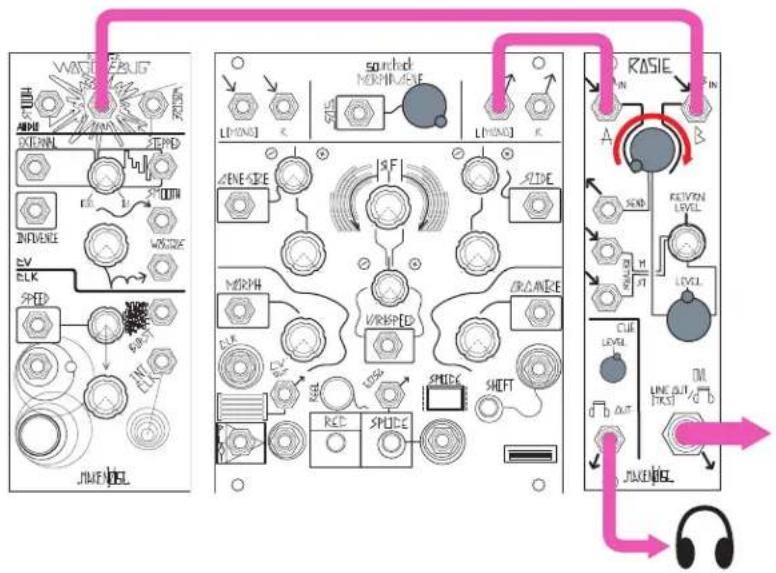
"DJ" Cueing System
Patch two audio signals to Ch. A and Ch. B Inputs. Choose patch to send to PA with Crossfader, output Master Line Output to PA. Monitor Cue Output with headphones to audition the other patch. When ready, use Crossfader to switch to the other patch in the PA.
flowchart
graph TD
    A["Input: WAT/BLIG"] --> B["Switched NORM/AVE"]
    B --> C["Line/INJ"]
    C --> D["RSIE"]
    D --> E["Output: JUWEI"]
    F["Input: AC/DC"] --> G["Switched NORM/AVE"]
    G --> H["Line/INJ"]
    H --> I["RSIE"]
    I --> J["Output: JUWEI"]
    K["Input: VOUT"] --> L["Line/INJ"]
    L --> M["RSIE"]
    M --> N["Output: JUWEI"]
    O["Input: AC/DC"] --> P["Switched NORM/AVE"]
    P --> Q["Line/INJ"]
    Q --> R["RSIE"]
    R --> S["Output: JUWEI"]
    T["Input: VOUT"] --> U["Line/INJ"]
    U --> V["RSIE"]
    V --> W["Output: JUWEI"]
    X["Input: AC/DC"] --> Y["Switched NORM/AVE"]
    Y --> Z["Line/INJ"]
    Z --> AA["RSIE"]
    AA --> AB["Output: JUWEI"]
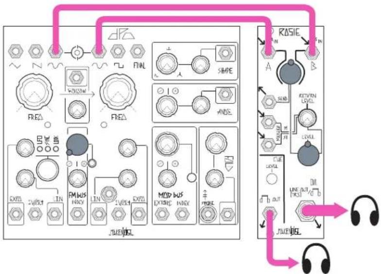
Two-input mixer
Patch two audio sources to Ch. A and Ch. B Inputs. Set mix with Crossfader. Take output from Master Line Output. With mix at 50%, the Master and Cue Outputs are identical, allowing multiple sets of headphones to monitor.
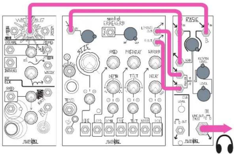
Start with DJ Cueing or Two-Input Mixer patch. Patch Send output to effects module of your choice, such as Erbe-Verb or Echophon. Set effects module Mix control to 100% wet, and patch its output to Mono Return input. For Stereo effects, patch left and right outputs of stereo effects module (such as Erbe-Verb) to L and R Return inputs on Rosie. Set effects volume with Return level control. Optional: Patching a VCA in series allows dynamic control of effects volume. For example, patch Send to an Optomix, take Ch1 Output to the Erbe-Verb Input, and use a cycling MATHS channel patched to the Optomix Control Input to dynamically modulate the level of signal being sent to the Erbe-Verb.
flowchart
graph TD
    subgraph Audio jack
        A["DAPI"] --> B["EXTRA"]
        B --> C["TIME"]
        C --> D["INFLUENCE"]
        D --> E["SV"]
        E --> F["CLK"]
        F --> G["SPED"]
        G --> H["AV"]
        H --> I["AV"]
        I --> J["JAKENJEL"]
    end

    subgraph Sound erpenerb
        K["SHED"] --> L["PREDelay"]
        L --> M["THLT"]
        M --> N["DECAY"]
        N --> O["LIMONOL OUT"]
        P["ARGARB"] --> Q["SUB"]
        Q --> R["REVEN LEVEL"]
        S["CUE LEVEL"] --> T["OUT"]
        U["d OUT"] --> V["JAKENJEL"]
    end

    subgraph RASIE
        W["IN"] --> X["SUB"]
        X --> Y["REVEN LEVEL"]
        Z["LEVEL"] --> AA["OUT"]
        AB["TM"] --> AC["OUT"]
        AD["JAKENJEL"] --> AE["JAKENJEL"]
    end

    J --> K
    K --> L
    L --> M
    M --> N
    N --> O
    O --> P
    P --> Q
    Q --> R
    R --> S
    S --> T
    T --> U
    U --> V
    V --> AB
    AB --> AC
    AC --> AD
    AD --> AE
Three-input mixer (2 mono channels + 1 mono/stereo channel) Start with Two-input mixer patch, and add a third audio source to one or both of the FX Return inputs. Set "channel 3" level with Return Level control.

flowchart
graph TD
    A["ST0"] --> B["RASIE"]
    B --> C["KEYVIN LEVEL"]
    C --> D["LEVEL"]
    D --> E["CUE LEVEL"]
    E --> F["LINE OUT EXCEL"]
    F --> G["JWINDL"]
    G --> H["JWINDL"]
    H --> I["MOD BUS EX15IC INOX"]
    I --> J["FM BUS INOX"]
    J --> K["EX2L 2V/OUT LIN"]
    K --> L["FREQ"]
    L --> M["RHEA"]
    M --> N["FINL"]
    N --> O["SHAPE"]
    O --> P["+"]
    P --> Q["Ground"]
Ping Pong Reverb
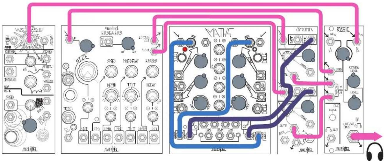
Patch audio of your choice to either or both of the Rosie inputs. Patch SEND Output to Erbe-Verb Input. Set Erbe-Verb Mix to 100% wet. Patch Erbe-Verb Left Output to Optimix Ch.1 Signal Input and Erbe-Verb Right Output to Optimix Ch.2 Signal Input. Set up MATHS for 281 Quadrature mode (see MATHS manual). Start with MATHS CH1 Cycling in order to Trigger Ch.4. Then, turn off Cycling on Ch.1. If performed correctly, the two Cycles on MATHS should be 180 degrees out of phase with one another. Now, patch MATHS Ch.1 Unity Output to Optimix Ch.1 CONTROL Input and MATHS Ch4 Unity Output to Optimix Ch.2 CONTROL Input. Patch Optimix Ch.1 Output and Ch.2 Output to M and S Return Inputs on Rosie. Set Return level, MATHS, and Erbe-Verb settings to taste. Take stereo output from Rosie Line Output. (OPTIONAL: use ModDemix instead of Optimix for different timbres.)
flowchart
graph TD
    A["Audio"] --> B["Speed"]
    B --> C["Pressure"]
    C --> D["Voltage"]
    D --> E["Power"]
    E --> F["MATHS"]
    F --> G["OPTICOMIX"]
    G --> H["RASIE"]
    H --> I["Cap"]
    I --> J["Switch"]
    J --> K["Ground"]
    style A fill:#f9f,stroke:#333
    style B fill:#ccf,stroke:#333
    style C fill:#cfc,stroke:#333
    style D fill:#fcc,stroke:#333
    style E fill:#cff,stroke:#333
    style F fill:#ffc,stroke:#333
    style G fill:#fcc,stroke:#333
    style H fill:#ffc,stroke:#333
    style I fill:#cfc,stroke:#333
    style J fill:#cfc,stroke:#333
    style K fill:#cfc,stroke:#333
    style L fill:#fcc,stroke:#333
    style M fill:#fcc,stroke:#333
    style N fill:#fcc,stroke:#333
    style O fill:#fcc,stroke:#333
    style P fill:#fcc,stroke:#333
    style Q fill:#fcc,stroke:#333
    style R fill:#fcc,stroke:#333
    style S fill:#fcc,stroke:#333
    style T fill:#fcc,stroke:#333
    style U fill:#fcc,stroke:#333
    style V fill:#fcc,stroke:#333
    style W fill:#fcc,stroke:#333
    style X fill:#fcc,stroke:#333
    style Y fill:#fcc,stroke:#333
    style Z fill:#fcc,stroke:#333
Stomp Box Integration using CV Bus (no adapter cables necessary)
Set up patch of your choice. Patch Send output to Mono input on CV Bus Output stage, setting level with the CV Bus output Level knob. Patch CV Bus 14 " output to first input on pedalboard. Patch final output of pedalboard to CV Bus 14 " Input, and set level with CV Bus input Level knob. Patch Output to Mono Return Input on Rosie, and set Return amount with Return Level control.