
DPO - Synthesizer Make Noise - Free user manual and instructions
Find the device manual for free DPO Make Noise in PDF.


| Product Type | Eurorack Synthesizer Module |
| Brand | Make Noise |
| Model | DPO (Dual Primary Oscillator) |
| Category | Voltage Controlled Oscillator / Complex Waveform Generator |
| Width | 28 HP (approx. 141.8 mm) |
| Depth | Approximately 30-40 mm (typical Eurorack module depth) |
| Power Requirements | +12V @ 70mA, -12V @ 70mA |
| Power Connector | 16-pin Eurorack ribbon cable (red stripe to -12V) |
| Oscillators | Two voltage-controlled oscillators (VCO A and VCO B) |
| Frequency Range | 12 Hz to 6 kHz (9.5 octave range via Coarse Tune) |
| Output Waveforms | VCO A: Triangle, Sawtooth, Sine; VCO B: Sine, Square (asymmetrical), Final (processed by Shape, Angle, Fold) |
| Modulation Buses | FM Bus and MOD Bus with multiple destinations |
| FM Capabilities | Dynamic FM, Circular FM, Bi-directional FM with FM Bus Index control |
| Timbre Controls | Shape, Angle, Fold (with CV inputs and attenuators) |
| Special Features | Hard Sync, Phase Lock, LFO mode, Strike input, Follow, Beat Frequency LED |
| Core Technology | 100% analog, vintage-voiced, uses vactrols for smooth response |
| Calibration | Front-panel accessible trimmers for 1V/Octave scale (VCO A and B); top-side trimmers for sine shape and amplitude; right-side trim for Fold gain |
| Warranty | One year from date of purchase (proof required). Excludes user-induced damage. |
| Maintenance | No user-serviceable parts. Keep dry and clean. Do not expose to extreme temperatures. |
| Safety | Use only specified power supply. Ensure correct polarity. Do not operate if damaged. |
Frequently Asked Questions - DPO Make Noise
User questions about DPO Make Noise
0 question about this device. Answer the ones you know or ask your own.
Ask a new question about this device
Download the instructions for your Synthesizer in PDF format for free! Find your manual DPO - Make Noise and take your electronic device back in hand. On this page are published all the documents necessary for the use of your device. DPO by Make Noise.
USER MANUAL DPO Make Noise
Make Noise warrants this product to be free of defects in materials or construction for a period of one year from the date of purchase (proof of purchase/invoice required).
Malfunction resulting from wrong power supply voltages, backwards power cable connection, abuse of the product or any other causes determined by Make Noise to be the fault of the user are not covered by this warranty, and normal service rates will apply.
During the warranty period, any defective products will be repaired or replaced, at the option of Make Noise, on a return-to-Make Noise basis, with the customer paying the transit cost to Make Noise.
Please contact Make Noise for Return To Manufacturer Authorization.
Make Noise implies and accepts no responsibility for harm to person or apparatus caused through operation of this product.
Please contact technical@makenoisemusic.com with any questions, needs & comments... otherwise go MAKE NOISE.
http://www.makenoisemusic.com
THANK YOU
Beta Analyst: Surachai
Test Subjects: Rob Lowe, Joseph Raglani
Spiritual Advisor: Richard Devine
Special Thanx to Don Buchla for his original and inspirational 259 and Music Easel.
Installation:
The Make Noise DPO is an electronic signal generator requiring 70mA of +/-12V of regulated power and properly formatted distribution receptacle to operate. It is designed to be used within the euro format modular synthesizer system.
Go to http://www.doepfer.de/a100_man/a100t_e.htm for the details of this format.
To install, find 28HP of space in your euro-rack synthesizer system, confirm proper installation of included power cable on backside of module (see picture below), plug the 16 pin end power cable into the euro-rack style power distribution board, minding the polarity so that the RED stripe on the cable is oriented to the NEGATIVE 12 volt supply line. This is USUALLY at the bottom.
Please refer to your case manufacturers' specifications for location of the negative supply.

Proper installation of included power cable on module. Please note the RED BAND.
Overview:
The DPO is a voltage controlled oscillator designed for generating complex waveforms and implementing FM synthesis within the analog domain. Expanding on the classic arrangement of Primary and Modulator Oscillators, the DPO has both of the VCOs operable as complex signal sources. It is in essence a Dual Primary Oscillator.
The DPO is also designed for fast live sound creation. The module groups functionality intuitively to make complex patching move more quickly, while still interacting in an exciting way with all other modules.
Dynamic FM, Circular FM, Hard Sync and Additive Harmonic synthesis processes are all achieved with internal routing on the DPO. The idea being that the artist will utilize patch cables to expand upon these standard concepts or interrupt them completely by simply patching into the associated modulation destinations.
The DPO has two modulation buses, each with multiple destinations, the depth of which is adjustable per destination. The original 259 style modulation routing is split within the DPO into dedicated FM and Mod buses and switching jacks are utilized to create internal routings that may be undone by patching an external signal to the CV inputs. The attenuator associated with the destination CV input sets the final depth while the MOD and FM INDEX controls will act as the dynamic master depth controls.
Throughout the DPO opto-isolators, commonly called Vactrols, are utilized as gain cells, and the result is that the module will have a slow and organic response to control signals. This manifests itself in the smooth crossfading and phase reversal of the SHAPE parameter, for example.
The DPO is a 100% analog, vintage voiced musical instrument and is not suitable for laboratory use.
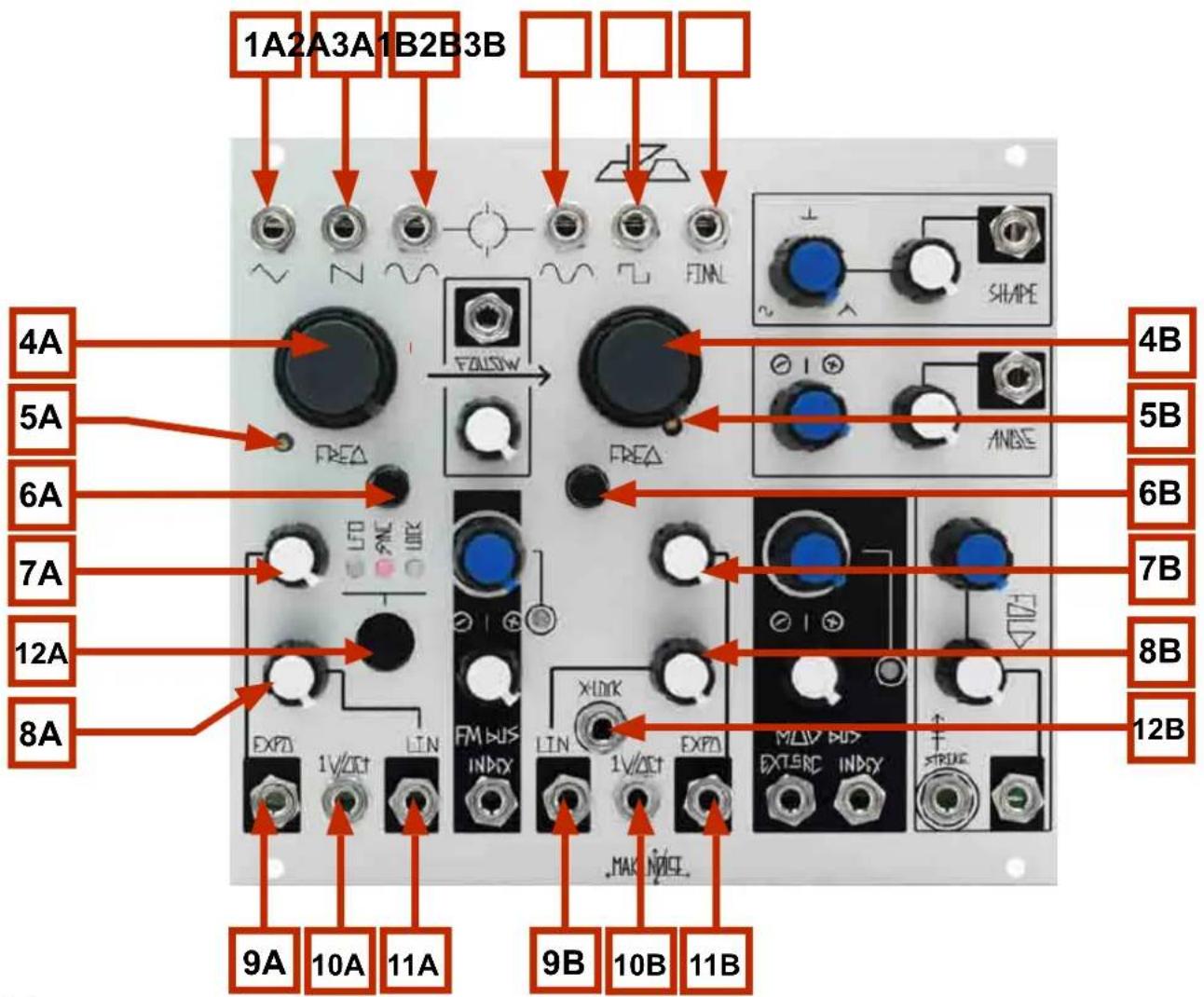
VCO A
1A Triangle Waveform OUT: 10Vpp
2A Sawtooth Waveform OUT: 9Vpp
3A Sine Waveform OUT: 10Vpp
4A Coarse Tune panel control: 9.5 octave range 12hz-6khz
5A 1V/ Octave Scale Trimmer (see calibration procedure)
6A Fine Tune panel control: 1.75 octave range
7A Expo Attenuator: uni-polar attenuator for Exponential frequency control input
8A Linear FM Attenuator: uni-polar attenuator for Linear FM input
9A Expo INput: Exponential frequency control input. normalled to FM Bus. bi-polar, 10V range
10A 1V/ Octave control INput: bi-polar pitch control, optimal range +/-5V
11A Linear FM INput: AC coupled, normalled to FM Bus, 10V range
12A VCO core behavior (Indicated by LED): No LED: Standard, BLUE: Phase LOCK to VCO B; PINK: Hard SYNC to VCO B; AMBER: Low Frequency Oscillator.
VCO B
1B Sine Waveform OUT: 10Vpp
2B Square Waveform OUT: 9Vpp Asymmetrical
3B FINAL Waveform: max 10Vpp Waveform as processed by Shape, Angle & Fold circuits
4B Coarse Tune panel control: 9.5 octave range 12hz-6khz
5B 1V/ Octave Scale Trimmer (see calibration procedure)
6B Fine Tune panel control: 1.75 octave range
7B Exponential Attenuator: uni-polar attenuator for Exponential frequency control input
8B Linear FM Attenuator: uni-polar attenuator for Linear FM input
9B Linear FM INput: AC coupled, normalled to FM Bus, 10V range
10A 1V/ Octave control INput: bi-polar pitch control, optimal range +/-5V
11B Expo INput: Exponential frequency control input. normalled to FM Bus. bi-polar, 10V range
12B eXternal-LOCK: allows VCO B to phase locked to hard edged signal (square, pulse or Sawtooth) from other VCOs.

VCO Interaction
- Beat Frequency LED: visual indication of Phase difference between VCOs A & B.
- FOLLOW CV INput: unipolar control input. Range 0V to 5V.
- FOLLOW Attenuator: determines how well VCO A will FOLLOW VCO B. With nothing patched to FOLLOW CV IN works as standard panel control. With Signal Patched to FOLLOW CV IN, works as an attenuator for that signal.
- FM BUS INDEX: unipolar panel control that sets the index (depth) of the FM.
- FM BUS INDEX LED: indicates the currently programmed FM Index Value.
- FM BUS INDEX CV Attenuator: bipolar attenuator for FM BUS INDEX CV IN
- FM BUS INDEX CV IN: bipolar control signal input. Range +/- 4V
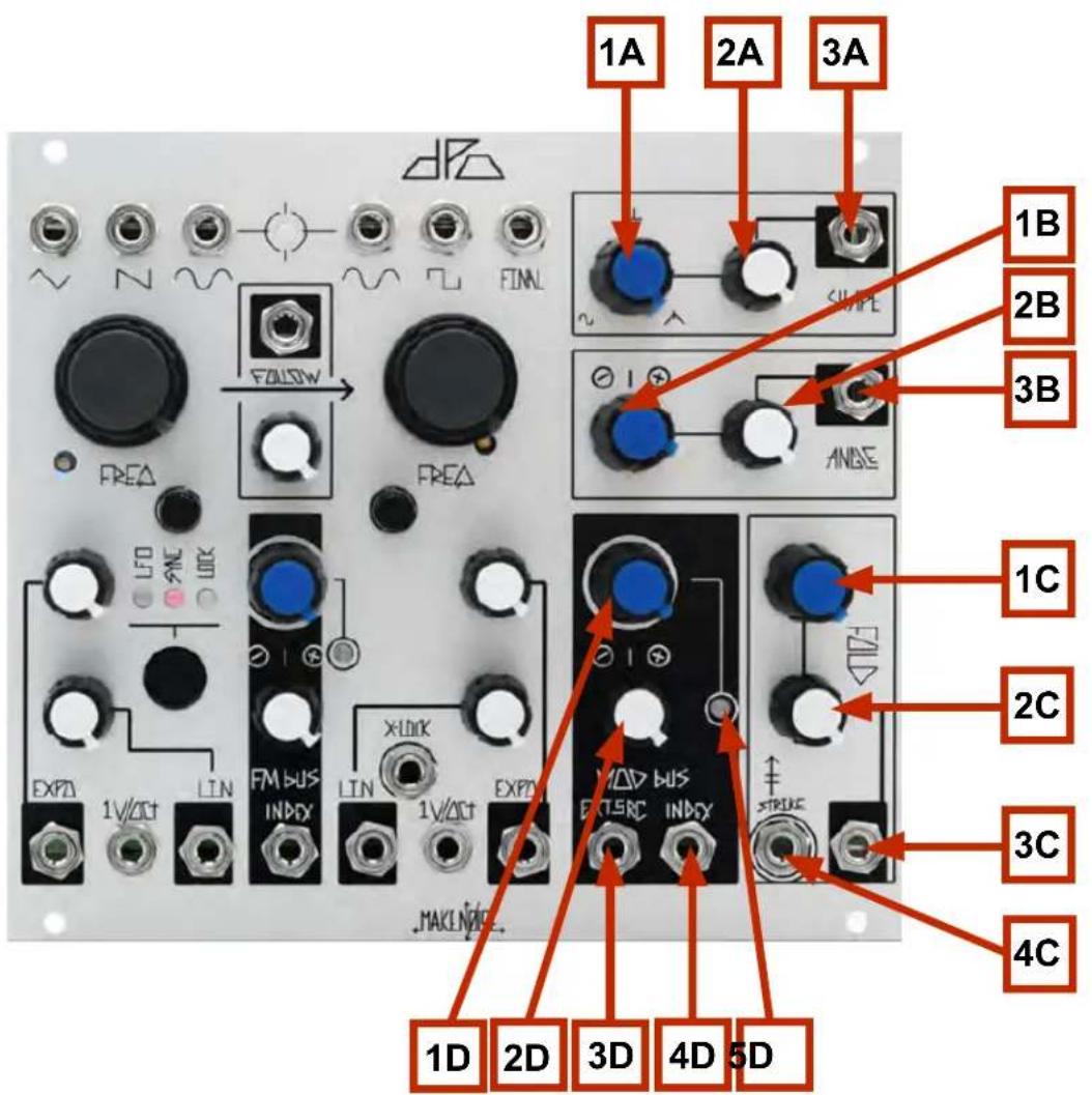
VCO B Timbre Controls and MOD Bus
1A. SHAPE Panel Control: unipolar control that determines the shape of the waveform feeding the FOLDing circuit. Morphs from Sine to Spike to Glitched Triangle.
2A. SHAPE CV Attenuator: unipolar attenuator for SHAPE CV IN.
3A. SHAPE CV IN: unipolar control signal input. Normalled into the MOD BUS. Range 0V to +5V.
1B. ANGLE Panel Control: tilts the added harmonics to either end of the wave-cycle. 2B. ANGLE CV Attenuator: unipolar attenuator for ANGLE CV IN.
2B: Angle CV Attenuator: unipolar attenuator for ANGLE CV IN.
3B. ANGLE CV IN: bi-polar control signal input. Normalled into the MOD BUS. Range 8V.
1C. FOLD Panel Control: unipolar control that continuously varies the low-order harmonics of the signal by folding the waveform into itself.
2C. FOLD CV Attenuator: unipolar attenuator for FOLD CV IN.
3C. FOLD CV IN: unipolar control signal input. Normalled into the MOD BUS. Range 0V to +8V.
4C. STRIKE IN: briefly opens the FOLD circuit to 100%, 8 to 10V Gate or clock.
1D. MOD BUS INDEX Panel Control: unipolar panel control that sets the index (depth) of the MOD Bus.
2D. MOD BUS INDEX CV Attenuator: bipolar attenuator for MOD BUS INDEX CV IN
3D. EXTernal SouRCe IN: interrupts internal routing of VCO A SINE as modulation source. +/-8V range.
4D. MOD BUS INDEX CV IN: bipolar control signal input. Range +/- 4V
5D. MOD BUS INDEX LED: indicates the currently programmed MOD Index Value.
Complex Waveforms through Frequency Modulation and SYNC:
On the DPO both VCOs are capable of generating complex and harmonically rich waveforms. This is accomplished through the use of FM and HARD SYNC on VCO A, and FM and Timbre Shaping on VCO B.
FM Bus
The internal FM bus is hardwired for SINE wave in both directions and makes use of the Normalization Switch found on the mini-jacks, so with nothing patched to the Linear and/ or Expo FM inputs the associated attenuator sets the final index of FM applied to each destination. As you increase the Index Level, the Amplitude of VCO A Sine Bused to VCO B Linear FM and Expo FM attenuators is increased. At the same time the Amplitude of VCO B Sine Bused to VCO A Linear FM and Expo FM attenuators is increased. Therefore you could have different amounts of Linear and Expo FM in BOTH directions, all at once. At greater than 90% Index, all of the FM bus lines (Linear, Expo for both VCOs) go into overdrive when the associated attenuators are set to beyond about 80%. The FM overdrive combined with the Bi-Directional Dynamic FM results in some extreme Circular FM capabilities. These sounds will get out of hand quickly. The key to controlled FM within the DPO is attenuation since setting the Index to 100% really does push the circuit to its limits.
VCO A core behavior
With none of the LEDs lighted VCO A operates as a Standard Triangle Core oscillator. When performing FM and Audio Rate modulations of Timbre parameters there will be greater chance for error in the frequency ratios. This is not always a bad thing. These errors manifest themselves in a looser interpretation of the ratio programmed, making each note have subtle differences.
The BLUE LED indicates LOCK, an extremely weak synchronization of VCO A to VCO B where as VCO A approaches an integer of VCO B frequency VCO A will reset to match VCO B and thus small tuning errors will be corrected. LOCK is useful for cleaning up FM patches where VCO A is acting as the modulator and VCO B is the carrier (the signal that is heard), as well as audio rate modulation of the VCO B Timbre parameters (via the MOD Bus). LOCK will not impart much change in the timbre of VCO A. It will not introduce strong harmonics. It is mostly used when VCO A is the modulating signal in an FM patch.
The PINK LED indicates Hard SYNC of VCO A to VCO B where VCO B will restart the period of VCO A at each cycle so they will have the same base frequency. SYNC will introduce strong harmonics to VCO A. SYNC is achieved when VCO A Frequency is HIGHER then that of VCO B. The timbre of VCO A may be altered by varying it's frequency against that of the Master Frequency set by VCO B. Slow modulation of VCO A Frequency, such as an envelope or LFO patched to VCO A EXPO CV IN, will result in sweeping of harmonics. The best results are achieved by setting VCO B to at least 100hz (around A2) and sweeping VCO A Frequency from 100hz up!
The AMBER LED indicates that VCO A is being operated as a Low Frequency Oscillator. This is very useful with the MOD BUS. Especially the SHAPE and ANGLE parameters respond well to LFO modulation.
VCO B is not directly affected by the VCO A LOCK, SYNC and LFO modes. However, if VCO A is used to modulate VCO B through the FM or MOD Buses, the resulting modulations will be affected by these settings.
VCO B core behavior
There is one way to affect the behavior of the VCO B core. The eXternal LOCK input allows for an extremely weak, phase reversed synchronization of VCO B to an external VCO where as VCO B approaches an integer frequency of the applied external VCO, VCO B will reset to match the external VCO, and thus small tuning errors will be corrected. eXternal LOCK is useful for cleaning up FM and audio rate modulation and will not impart much change in the timbre or introduce strong harmonics to VCO B. It is useful for chaining together multiple DPOs (or DPO and other VCO) for more complex FM, chords and other patches where tuning errors need to be minimized.
Because eXternal LOCK input is phase reversed, it is also possible to achieve very interesting amplitude modulations by summing VCO B along with a signal from the VCO supplying the eXternal LOCK input. Because their phase is reversed, as long at the VCO cores remained locked, there will be varying degrees of cancellation between the two VCOs, depending upon the wave shapes and levels programmed at the summing stage. By modulating VCO B frequency (through EXPO CV IN) it is possible to knock VCO B out of eXternal LOCK, and thus amplitude is regained.
The eXternal LOCK input expects a 10Vpp square or pulse shaped signal, however just about any signal could be used with varying degrees of success. The Duty Cycle (width) and Amplitude (height) of the signal will have some affect on the outcome.
FOLLOW
If you patch a sequencer or KB controller to the VCO B 1V/ Octave input and set the FOLLOW control to 100% VCO A will follow the pitch tracking of VCO B. As FOLLOW is decreased from 100% VCO A will lag further and further behind VCO B to the point of not actually following. At 0% FOLLOW, VCO A is independent of VCO B. If you patch into the Follow CV IN, then the associated potentiometer becomes an attenuator for the incoming CV (as on the Optomix CV ins), allowing for external control over how VCO A follows VCO B.
Follow is useful in maintaining FM or SYNC Ratios while controlling the DPO with a sequencer or keyboard. The lag that occurs when FOLLOW is set to less than 100% will introduce moments of dissonance and noise due to the temporary tracking errors. This is a wonderful way to introduce uncertainty to an otherwise stable sequence of notes.
Beat Frequency LED
This LED gives visual indication of phase difference between VCO A and B. It is useful for fine tuning simple oscillator frequency relationships such as unison, octaves and fifths. As the two oscillators approach these musical relationships you will see this LED flash more slowly. This LED is also useful for visual indication of the rate of the LFO when VCO A is programmed for LFO operation.
MOD BUS and Timbre Shaping Sections:
Mod Bus
The internal Mod Bus SOURCE is hardwired for VCO A SINE wave, with the power to use any external source by patching to the EXT. SouRCe Input. The internal MOD bus system makes use of the Normalization Switch found on the mini-jacks, so with nothing patched to the Shape, Angle and Fold CV inputs the associated attenuator sets the final amount of modulation applied to the destination. As you increase the Index level, the amplitude of VCO A Sine bused to the SHAPE, ANGLE and FOLD jacks is increased. Therefore you could have different amounts of modulation at each of the destinations (SHAPE, ANGLE, FOLD).
TIMBRE
The 3 parameters that are modulated by the MOD Bus shape the signal that is output at the FINAL OUT.
The top-most parameter in the Timbre section, SHAPE, adds higher order harmonics to the signal by morphing from SINE (0%) to SPIKE (50%) to Glitched Triangle (100%) while at the same time inducing phase reversal and amplitude modulation around the 50% range of the parameter value. This might sound like an odd collection of waveforms and functions, but the selection is quite useful.
The SINE wave is the classic waveform that would feed a wave folder, as utilized in both the Buchla 259 and the Buchla Music Easel Timbre circuits. Since wave-folding introduces lower order harmonics to the signal, the extremely low amount of harmonics in a SINE wave allows the circuit to do its job perfectly, resulting in smooth and glitch-free folding of the waveform.
The Spike shape on the other hand is rich in higher ordered harmonics and morphing from SINE to SPIKE without any folding of the waveform (FOLD set 10% to 30%) provides something like the effect of high pass filtering. The SPIKE waveform is useful in providing a strong group of harmonics for the ear to follow while modulating the ANGLE parameter or utilizing the lower octaves (mix with the SINE OUT to brighten bass sounds). The SPIKE wave shape is thin and resonant sounding, making the FOLD circuit feel almost anemic (in contrast to being fed a full blooded SINE shape).
The Glitched Triangle brings the combination of the strong Harmonic that makes the ANGLE modulations so animated and the girth of the SINE wave that gives the FOLD circuit some fat to chew, er FOLD!
The phase reversal and Amplitude Modulation that occurs around the 50% range of the SHAPE parameter value is useful on it's own (before FOLDing occurs) for subtle and pleasing modulations via LFO. The SHAPE circuit is slow and smooth with a unique response quite unlike the typical balanced modulator or VCA. When this element of the SHAPE circuit is utilized with FOLDing, the AM and Phase Reversal will act to drop and/or reverse folds resulting in deeper animation of the Timbre. When combined with slow modulation of the FOLD and ANGLE parameters, it is possible to achieve extremely animated sounds with just a single modulation source.
The ANGLE parameter injects a signal into the FOLD circuit at a node that results in pushing or tilting the circuit to one side or another. The net result is quite dependent upon the SHAPE and FOLD parameters. SINE shape results in Asymmetrical folding and additionally, thresholds of the FOLD circuit may be pre-maturely exceeded resulting in linear amplitude loss in some FOLDs. It is almost subtractive in nature.
Where the ANGLE parameter really shines, is in the animation of the higher order harmonics added to the signal by the SHAPE control. Slow modulation of the ANGLE parameter will push the SPIKE shape throughout the entire wave cycle continuously, and the result sounds like a combination of Phase Shifting and deep Pulse Width Modulation. The Glitched Triangle is a combination of the Asymmetrical folding and this Phase Shift/ PWM effect. Again, slow modulation is the key here, giving the ear a strong and entertaining harmonic to follow as it dances atop the long wave-cycles of the lower octaves. Perfect for animating bass lines. It also adds shimmer to the upper octaves, especially when the rate of modulation is increased to the lower audio registers.
The FOLD parameter is the final stage of the Timbre section and its behavior is greatly determined by the SHAPE and ANGLE parameters. The first 30% or the parameter value will act as a VCA, and is useful for creating percussive sounds. The after about 30% the FOLD circuit will reach its first threshold and from this point on is nothing like a VCA.
When SHAPE is set to 0% and ANGLE is set to around 50%, the FOLD circuit is fed a symmetrical SINE wave and increasing the FOLD parameter beyond 30% will result in the continuous introduction of lower-order harmonics. This Additive process was unique to the Buchla instruments developed in the early days of synthesis (Music Easel and 259 module) and is opposite to the process of filtering utilized for Subtractive synthesis popularized by the Moog synthesizers (Minimoog). The sound is large and quite aggressive. While it is the opposite of the filtering process it responds to modulations is a very similar way, with sweeping envelopes, SINE or Triangle LFOs and Audio Rate modulations being quite effective.
When Shape is set to SPIKE or Glitched Triangle, there will be fewer of the lower order harmonics audible and the higher order harmonics present in the SPIKE and Glitched Triangle signals will smear the sound with soft noise. The FOLD circuit is not able to work perfectly with these signals, and the results are very interesting.
On the reception of a Gate or Clock Pulse, STRIKE will very briefly open the FOLD circuit to 100%. STRIKE is useful for creating percussive sounds, accents and audio rate modulation of the FOLD circuit.
The OTHER WAVEFORM OUTPUTS
In addition to the FINAL out there are several wave shapes that are all tapped or derived from the oscillator cores. Except for the VCO A SAW and VCO B SQUARE, these signals are all around 10V peak to peak and centered around 0V (bi-polar).
The SINE wave is derived from the TRIANGLE core of both oscillators and is provided as an output for both VCO A and B because it is great for blending with signals of greater harmonic content in order to strengthen the fundamental. The SINE shape has almost no harmonics, so it is also a good starting point for creating complex FM sounds because the sidebands introduced through FM will not be obscured by harmonics present in the signals utilized.
For VCO A the TRIANGLE shape is tapped from the core of the oscillator. The TRIANGLE is especially useful for modulation of the SHAPE parameter. The narrower top and bottom portions of the waveform let the SHAPE circuit breath a bit more than the SINE wave and the result is that deeper modulation is possible before complete saturation of the SHAPE circuit occurs. The TRIANGLE shape is also a great signal to tap when performing Hard SYNC. The small amount of additional harmonics makes the SYNC process more audible (than it will be when using the SINE), without getting quite as aggressive as the SAW shape. Like the SINE wave, the TRIANGLE shape is also excellent for blending with signals of greater harmonic content in order to strengthen the fundamental.
VCO A also offers a unique SAW shape that is derived from the TRIANGLE core. It is not the typical saw waveform as it has a stronger fundamental then is usually heard in a sawtooth shape. This waveform is selected for VCO A in order to provide a unique response to the harmonically rich FINAL OUT signal of VCO B. The SAW shape will carry the harmonics and sidebands introduced through Hard SYNC and FM with greater presence then the TRIANGLE or SINE shapes. The end result is that the SAW will be the most aggressive signal when using Hard SYNC or FM. The SAW shape is also a good alternative to the SINE shape utilized throughout the MOD Bus. Patching the SAW to the EXT. SouRCe Input of the MOD Bus with yield a completely different set of timbres. Especially the FOLD circuit will respond wonderfully to the more aggressive SAW shape. Finally, SAW shape is also excellent for patching Subtractive synthesis sounds.
In addition to the SINE shape, VCO B offers the FINAL OUT (discussed at length in the MOD Bus and Timbre Shaping Sections) and an Asymmetrical SQUARE waveform that is tapped off the core of the oscillator. The SQUARE is not AC coupled and it therefore has very steep slopes and hard edges. The asymmetrical shape was chosen so that when blended with symmetrical signals, it is possible to achieve asymmetrical clipping of those signals at the input of a filter or summing stage. SQUARE is the waveform of choice for performing eXternal LOCK patches between multiple DPOs where the chain of command is passed from one DPO down to the next. Like the SAW, the SQUARE shape is also very useful for performing Subtractive synthesis.
Patch Ideas:
Animated Lead:
Patch sequencer or keyboard CV to VCO B 1V/ Octave INput. Monitor VCO B FINAL OUT. Set SHAPE and ANGLE panel controls and CV Attenuators to NOON. Set FOLDS to 9 o' Clock and set FOLDS CV attenuator to NOON. Set Mod Bus panel control to NOON. Patch Gate from sequencer or CV KB to STRIKE INput of DPO. Push button to select LFO behavior at VCO A. Set VCO A FREQ. to around 9 o' Clock and set Follow p to full clockwise (100%). Varying the Mod Bus parameter will greatly alter the sound.
Analog Bass Drum: Patch VCO A SINE to Optimix CH. 1 Signal IN. Patch Gate from René or other sequencer to DPO VCO A Linear FM IN and Optimix CH. 1 Strike IN. Set DPO VCO A Linear FM amount to 50% and Frequency panel control to roughly 9 o'clock. Set Optimix CH. 1 Damp and Control panel controls to full Counter Clock-Wise. Monitor Optimix CH. 1 Signal OUT. Adjusting the Linear FM amount, Frequency setting and DAMP settings will allow you to create many different Bass Drum sounds. Adding Dynamic Expo FM from VCO B by patching same gate to FM INDEX IN will also expand the possibilities.
Skronky FM
Engage SYNC mode on VCO A. Monitor VCO B SINE Output. Tune the two oscillators to a simple interval such as unison, a fifth or an octave. Adjust FOLLOW panel control to about 3:00. Turn up VCO B Lin FM attenuator to 12:00. Turn FM BUS to 12:00. Send a sequence or keyboard voltage to VCO B 1v/oct. Each note change will be accompanied by a discordant squelch of FM as VCO A “slides” to the correct note. Adjust Follow and FM amounts to taste.
Strike Force
Monitor FINAL output. Turn Folds and SHAPE to 0 (full CCW). Turn SHAPE and FOLD CV input attenuators to 12:00. Patch Pressure Points common Gate out to STRIKE input, Pressure Points tuned voltage B or C to DPO VCO B 1v/oct, and Pressure Points common Pressure out to Mod Bus EXT SRC Input. Sound will become simultaneously louder and more “damped” as more pressure is applied. Adjust Pressure Points sensitivity and SHAPE/FOLD CV input attenuators to taste.
Wobble Bass
Monitor FINAL output. Adjust Fold, Angle, Shape panel controls and input attenuators to 12:00. Set VCOA to LFO mode with coarse Freq \~9:00. Adjust Mod Bus Index Panel control full CW, and FM Bus Index panel control full CCW. Adjust Follow panel control full CW. Patch sequencer or keyboard CV to VCOB 1v/oct. "Wobbling" will change speed with the pitch of the "bassline", doubling frequency per octave. Adjust coarse frequency knobs and Final parameters and CV input attenuators to taste.

Calibrating the DPO
Requires small flat head screw driver or trimmer tool, tuned reference signal, oscilloscope.
NOTE: if you plan to use the DPO with another VCO or Synth in your system (even another DPO), it is a good idea to use that VCO/ Synth for your reference signal, assuming it is calibrated to your satisfaction. The same is true of the quantizer or MIDI to CV interface. Use the unit within your system. If you use one, a digital midi controlled soft synth is also a nice reference signal and note generator. Be certain the reference is not processed in any way by effects or filters or any other processes.
1V/ Octave Scale
Trims for 1V/ Octave Scaling (3A, 3B) are accessed from the front of the module so that user need not remove the module from the system to calibrate 1V/ Octave Scaling. Calibrate the DPO while installed in the system in which it will be utilized.
-
Monitor VCO B SINE (1B).
-
Patch quantizer or MIDI to CV interface to 1V/ Octave INput (6), set FOLLOW (5) to 0% (full counter clockwise).
-
Patch this same quantizer or MIDI to CV signal to the reference oscillator and monitor together with the DPO VCO B SINE. If using digital/ soft synth for reference, just pass midi note to MIDI to CV interface connected to DPO.
-
Send note C6 to the both DPO VCO B and your reference oscillator, and adjust the FREQ (2A) and FINE TUNE (4A) Panel Controls so the DPO pitch matches that of the reference.
-
Send note C3 to the both DPO VCO B and your reference oscillator, and adjust the 1V/ Octave Trimmer (3B) on the DPO so the pitch matches that of the reference.
-
Repeat steps 3 and 4 until satisfaction or exhaustion is achieved.
-
Check across 4 or 5 octaves and adjust if necessary. The DPO will track musically. Expect variance across 4 octaves. Get the tuning so it is useful to you, and move on to VCO A (next step).

- To calibrate VCO A 1V/ Octave Scale, use VCO B (that is now tuned) as reference.
- Monitor VCO A and B SINEs. Patch or Midi to CV to VCO A 1V/ Octave INput (6), and FOLLOW (5) still at 0% .
- Send note C6 to the DPO and adjust the VCO A FREQ (2A) and FINE TUNE (4A) Panel Controls so the DPO VCO A pitch matches that of the reference (DPO VCO B).
- Send note C3 to the DPO and adjust the VCO A 1V/ Octave Trimmer (3A) on the DPO so the pitch matches that of the reference.
- Repeat steps 3 and 4 until satisfaction or exhaustion is achieved.
- Check across 4 or 5 octaves and adjust if necessary. The DPO will track musically. Expect variance across 4 octaves. Get the tuning so it is useful to you, and then go make noise!

VCO SINE Shape and Amplitude
Trims for SINE shape (1A, 1B) and Amplitude (3A, 3B) are accessed through the top side of the module. Take care in lifting the top half of the module out of case for calibration.
- Monitor the SINE (2A, 2B) from the VCO to be calibrated. If possible view the signal on an oscillo scope and/or spectrum analyzer as well.
- Set VCO to be calibrated near to frequency of C4. (4A, 4B)
- Set oscilloscope for 2V/ div. by 2ms/ div. (skip to step 4. if no oscilloscope will be used).
- Trim SINE Shape (1A, 1B) for least amount of audible harmonics (skip to step 5 if using oscilloscope).
- If using an oscilloscope or spectrum analyzer adjust so the SINE shape is pure as possible, meaning both the top and bottom arches are smooth, rounded and glitch free, and harmonics are minimized.
- Amplitude is adjusted by trim 3A, 3B. Amplitude should be set using oscilloscope for measurement, to roughly 10.5V peak to peak for VCO A and roughly 10.2V peak to peak for VCO B. There is some cases where amplitude of VCO B will need to be greater or less than the above specification in order for the, FM Bus and Fold circuits to operate correctly. See the last step of the VCO B FINAL OUT Calibration for more details.
NOTE: Amplitude should not require adjustment in most cases.
Expect some small amount of harmonics in the SINE shape. Trim to satisfaction and then go make noise!

Calibrating the VCO B FINAL OUT
Trims for FINAL OUT are SHAPE Balance (3) which is accessed through the top side of the module and FOLD Gain (4) which is accessed through the right side of the module. Take care in lifting the module out of case for calibration.
- Before this calibration may be performed, the SINE Shape and Amplitude calibration must be completed.
- Monitor the VCO B FINAL OUT (2) and view the signal on an oscilloscope set for 2V/ div. by 2ms/ div.
- Set VCO B to be near to frequency of C4.
- Make the following setting in the Timbre section:
FOLD parameter to around 25% so you are able to see a sine wave on the oscilloscope.
ANGLE parameter set to around 50% so the waveform is symmetrical.
SHAPE parameter to 100%, take note of the "maximum shape," after the calibration this same shape should form with SHAPE set to 100%. Now set SHAPE to 50%.
-
Adjust SHAPE trim (3) so the sine shape is minimized, and the waveform is a SPIKE.
-
Set SHAPE to 100% and check that the "maximum shape" waveform appears as it did at end of step 4. If not, adjust SHAPE trim (3) minimally, splitting the difference between the optimal maximum setting and the optimal SPIKE setting.
-
Return SHAPE to 0%.
-
Slowly turn FOLD to 100% counting 5 folds in the waveform. With FOLD at 100% take note of the widest portion of the waveform. This is the Fundamental Fold.
-
Turn FOLD gain CW until the widest portion of the waveform stops increasing in width.
-
Turn FOLD CCW down to 50% counting the unfolding. The last two folds (4 and 5) should come undone by around 50% of the FOLD parameter. If not, then adjust FOLD Gain trim (5) for the optimal setting, splitting the difference between the widest fundamental fold, and complete unfolding of last two folds at 50% FOLD setting. If needed, Amplitude of VCO B SINE might require adjustment as well in order to make all 5 folds occur (increase amplitude) or to meet the requirement of unfolding the last two folds by the 50% parameter value (decrease amplitude). The most important thing is that the FOLD circuit sounds good though, so give it a listen.


- THANK YOU
- INSTALLATION
- OVERVIEW
- VCO A
- VCO B
- VCO INTERACTION
- VCO B TIMBRE CONTROLS AND MOD BUS
- COMPLEX WAVEFORMS THROUGH FREQUENCY MODULATION AND SYNC
- FM BUS
- VCO A CORE BEHAVIOR
- VCO B CORE BEHAVIOR
- FOLLOW
- BEAT FREQUENCY LED
- MOD BUS AND TIMBRE SHAPING SECTIONS
- MOD BUS
- TIMBRE
- THE OTHER WAVEFORM OUTPUTS
- PATCH IDEAS
- ANIMATED LEAD
- SKRONKY FM
- STRIKE FORCE
- WOBBLE BASS
- CALIBRATING THE DPO
- 1V/ OCTAVE SCALE
- VCO SINE SHAPE AND AMPLITUDE
- CALIBRATING THE VCO B FINAL OUT
Brand : Make Noise
Model : DPO
Category : Synthesizer