
M185LCBV4 - Surveillance Speco Technologies - Free user manual and instructions
Find the device manual for free M185LCBV4 Speco Technologies in PDF.

| Product Type | LCD CCTV Monitor |
| Brand | Speco Technologies |
| Model | M185LCBV4 |
| Size | 18.5 inches |
| Aspect Ratio | 16:9 |
| Resolution | 1360 x 768 pixels |
| Display Colors | 16.7 million |
| Brightness | 300 cd/m² |
| Contrast Ratio (DCR) | 10000:1 |
| Response Time | 5 ms |
| Viewing Angle (H/V) | 170° / 170° |
| Video Inputs | BNC x1, VGA x1 |
| Video Output | BNC x1 |
| Audio Input | Stereo PC audio |
| Audio Output | Line out |
| Built-in Speakers | 2 x 2 watts |
| Power Supply | AC 110-240 V, 50/60 Hz |
| Power Consumption | < 20 W |
| Power Management | On (Green), No Signal (Flashing Green), Off (No Light) |
| VESA Mount | 100 x 100 mm |
| Dimensions (L x D x H) | 444.2 x 138 x 350.7 mm |
| Net Weight | 3.58 kg |
| Gross Weight | 4.5 kg |
| Operating Temperature | 0°C to 50°C |
| OSD Languages | English, French, Korean, Chinese |
| Certifications | FCC, CE, CB, RoHS |
| Accessories Included | Power cord, VGA cable, Audio cable, Quick Installation Guide |
| Cleaning Method | Unplug, use damp cloth only; no liquid or aerosol cleaners |
| Safety Features | Grounded plug, ventilation, no user-serviceable parts |
| Mounting Compatibility | Wall or VESA arm; use M4 x 8 mm screws (not included) |
Frequently Asked Questions - M185LCBV4 Speco Technologies
User questions about M185LCBV4 Speco Technologies
0 question about this device. Answer the ones you know or ask your own.
Ask a new question about this device
Download the instructions for your Surveillance in PDF format for free! Find your manual M185LCBV4 - Speco Technologies and take your electronic device back in hand. On this page are published all the documents necessary for the use of your device. M185LCBV4 by Speco Technologies.
USER MANUAL M185LCBV4 Speco Technologies
User Manual M185LCBV4 and M215LCBV4
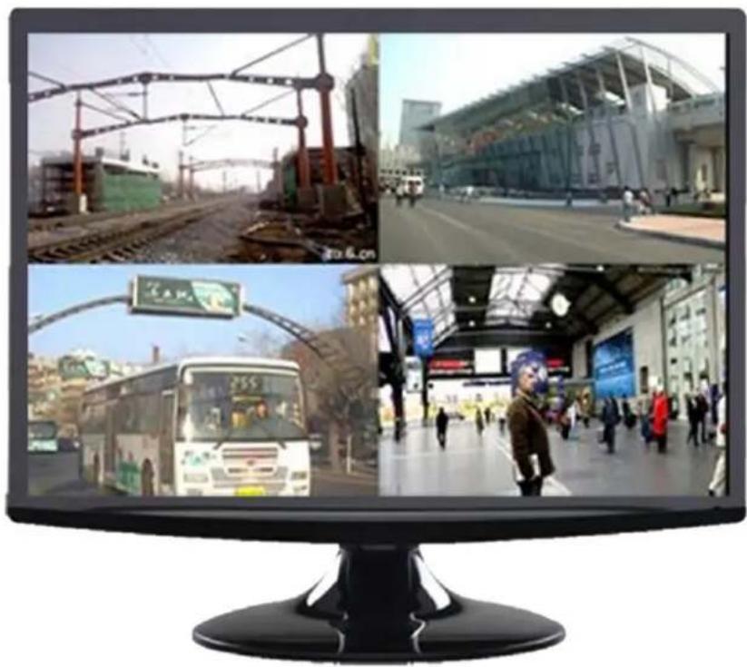
natural_image
Computer monitor displaying four interior scenes: railway tracks, modern airport, bus stop, and pedestrian crossing (no visible text or symbols)LCD VIDEO MONITOR
speco technologies®
Contents
SAFETY INSTRUCTIONS....2-3
CAUTION 4
FCC RF INTERFERENCE STATEMENT ....5
CONNECTING WITH EXTERNAL EQUIPMENT 6
CONTROLS AND FUNCTIONS....7-16
MOUNTING GUIDE 17
D-SUB CONNECTOR PIN ASSIGNMENTS 18
POWER MANAGEMENT....19
SPECIFICATIONS....20
This Monitor was
Manufactured in ISO 9001
Certified Factory
Safety Instructions
- Read all of these instructions.
- Save these instructions for later use.
- Follow all warnings and instructions in this manual and on the product.
- Unplug this product from the wall outlet before cleaning. Do not use liquid or aerosol cleaners. Use a damp cloth for cleaning.
- Do not use this product near water.
-
Do not place this product on an unstable cart, stand, or table. The product may fall, causing serious damage to the product or nearby people.
-
Please comply with the following conditions:
A. Allow a minimum distance of 10cm around the apparatus for sufficient ventilation.
B. The ventilation openings should not be impeded by items such as paper, table-cloths, curtains, etc..
C. No naked flame sources, such as lighted candles, should be placed on the apparatus.
D. Please dispose of all batteries according to local regulations.
E. Use the monitor in moderate climates.
-
This product should be operated from the type of power source indicated on the marking label. If you are not sure of the type of power available, consult your dealer or local power company.
-
This product is equipped with a 3 wire grounding type plug having a third (grounding) pin. This is a safety feature. If you are unable to insert the plug into the outlet, contact your electrician to update the outlet. Do not defeat the purpose of the grounding-type plug.
-
Do not allow anything to rest on the power cord or place this product where people will walk on the cord.
-
If an extension cord is used with this product, make sure that the total ampere ratings on the products plugged into the extension cord does not exceed the extension cord ampere rating. Also, make sure that the all of the products plugged into the wall outlet do not exceed the rating of the outlet.
-
Never push objects of any kind into this product through cabinet slots as they may touch dangerous voltage points or short out parts, which could result in the risk of fire or an electric shock. Never spill any kind of liquid on the product.
-
Do not attempt to service this product yourself, as opening or removing covers may expose you to dangerous voltage points or other risks. Refer all servicing to trained personnel.
Safety Instructions
- Unplug this product from the wall outlet and refer servicing to qualified service personnel under the following conditions:
A. When the power cord or plug is damaged or frayed.
B. If liquid has been spilled into the product.
C. If the product has been exposed to rain or water.
D. If the product does not operate normally when the operating instructions are followed. Adjust only those controls that are covered by the operating instructions since improper adjustment of other controls may result in damage and will often require extensive work by a qualified technician to restore normal operation.
E. If the product has been dropped or the cabinet has been damaged.
F. If the product exhibits a distinct change in performance, indicating a need for service.
CAUTION
The power supply cord is used as the main disconnect device. Ensure that the socket-outlet is located/installed near the equipment and is easily accessible.
CAUTION TO SERVICE PERSONNEL
POWER SUPPLY CORD IS USED AS MAIN POWER DISCONNECT DEVICE IN THIS PRODUCT. UNPLUG THIS PRODUCT FROM THE WALL OUTLET BEFORE REMOVING THE BACK COVER AND SERVICING
EMISSION CHARACTERISTICS TESTED BY SEMKO
THIS PRODUCT HAS BEEN TESTED AND HAS SHOWN COMPLIANCE WITH THE NATIONAL SPECIFICATIONS SUCH AS SWEDISH MPR 1990.10.(MPR II)
Cautions
▶ NEVER REMOVE THE BACK COVER
Removal of the back cover should be carried out only by qualified personnel.
▶ DO NOT USE IN HOSTILE ENVIRONMENTS
To prevent electrical shock or a fire hazard, do not expose the unit to rain or moisture. This unit is designed to be used in the office or home. Do not subject the unit to vibrations, dust, or corrosive gases.
▶ KEEP IN A WELL VENTILATED PLACE
Ventilation holes are provided on the cabinet to prevent the temperature from rising. Do not cover or place anything on top of the unit.
▶ AVOID HEAT
Avoid placing the unit in direct sunshine or near a heating appliance.
▶ TO ELIMINATE EYE FATIGUE
Do not use the unit against a bright back ground or where sunlight and other light sources will shine directly on the monitor.
▶ BE CAREFUL OF HEAVY OBJECTS
Neither the monitor itself nor any other heavy object should rest on the power cord. Damage to a power cord can cause fire or electrical shock.
FCC RF Interference Statement
NOTE
This equipment has been tested and found to comply with the limits for a Class B digital device, pursuant to Part 15 of the FCC Rules. These limits are designed to provide reasonable protection against harmful interference in a residential installation.
This equipment generates, uses, and can radiate radio frequency energy and, if not installed and used in accordance with the instructions, may cause harmful interference to radio communications. However, there is no guarantee that interference will not occur in a particular installation.
If this equipment causes harmful interference to radio or television reception, which can be determined by turning the equipment off and on, the user is encouraged to try to correct the interference by one or more of the following measures.
- Reorient or relocate the receiving antenna.
- Increase the space between the equipment and receiver.
- Connect the equipment into an outlet on a circuit different from that to which the receiver is connected.
- Consult the dealer, an experienced radio, or a TV technician for help.
- Only a shielded interface cable should be used.
Finally, any changes or modifications to the equipment by the user not expressly approved by the grantee or manufacturer could void the user's authority to operate such equipment.
▶ DOC COMPLIANCE NOTICE
This digital apparatus does not exceed the Class A limit for radio noise emissions from digital apparatus set out in the radio interference regulation of Canadian Department of Communications.
This monitor complies with the basic protection requirements of the Electromagnetic Compatibility (EMC) Directive 2004/108/EC for electrical and electronic equipment imported into the European Union (EU): The electromagnetic disturbance generated by the apparatus does not exceed the level specified in the harmonized EMC Standards for this type of apparatus. It has a level of immunity to the electromagnetic disturbance to be expected in its intended use, and should operate without unacceptable degradation of

its specified performance.
Connecting with External Equipment
Bottom and Side Panel Control
Back View of Monitor

natural_image
Back view of a computer monitor with ventilation grilles and a stand, showing no text or symbols on the device itself.A. Connector Panel

| 1. Audio In | 2. Audio Out | 3. BNC Out | 4. BNC In | 5. VGA |
INSTRUCTION MANUAL....6
Key Control and Source Menu
B. CONTROL KEYS/BUTTONS
Buttons are located on the back of the monitor on the right side of the Bezel.

-
Menu/Source: Opens the OSD and steps down on the OSD. Also, the MENU button selects either the VGA or BNC input after the EXIT button is pushed) and then press the MENU button to Select
-
Up: Increases the volume or moves the selector/indicator right in the OSD
-
Down: Decreases the volume or moves selector/indicator left in the OSD
-
Exit: Press MENU button to select the input (first push EXIT and then MENU button) or to exit the OSD
OSD Menu Functions and Settings
1. OSD setup under BNC input mode
A. COLOR MENU
Press the MENU button to bring the menu on screen, and then Up/Down buttons to move left and right across the menu selections to highlight the COLOR menu. Press the Menu (Source) button to enter the (highlighted) COLOR sub menu.
Each additional press of the Menu/Source button moves the yellow highlighted sub-menu selection downward, moving from the bottom selection back to the top of the sub-menu. Pressing the Up /
Down buttons will adjust the value of the highlighted item. Press the MENU button to save the values.
Press EXIT to exit the sub-menu, and go back to the main menu choices. Pressing the EXIT button while at the top level will close the menu and return to normal operations.

Adjustments
Contrast: Adjusts the contrast between light and dark areas of the picture.
Brightness: Adjusts the overall picture shade and brightness.
Saturation: Increase or decrease the saturation of the image.
Sharpness: Increase or decrease the sharpness of the image.
Hue: Increase or decrease the hue or tint of the image.
OSD Menu Functions and Settings
1. OSD setup under BNC input mode (continued)
B. AUDIO MENU
Press the MENU button to bring the menu on screen, and then Up / Down buttons to move left and right across the menu selections to highlight the AUDIO menu. Press the Menu (Source) button to enter the (highlighted) AUDIO sub menu.
Pressing the Up/ Down buttons will adjust the value of the highlighted item. Press the MENU button to save the values. Press EXIT to exit the sub-menu and go back to the main menu choices. Pressing the EXIT button while at the top level will close the menu and return to normal operations.
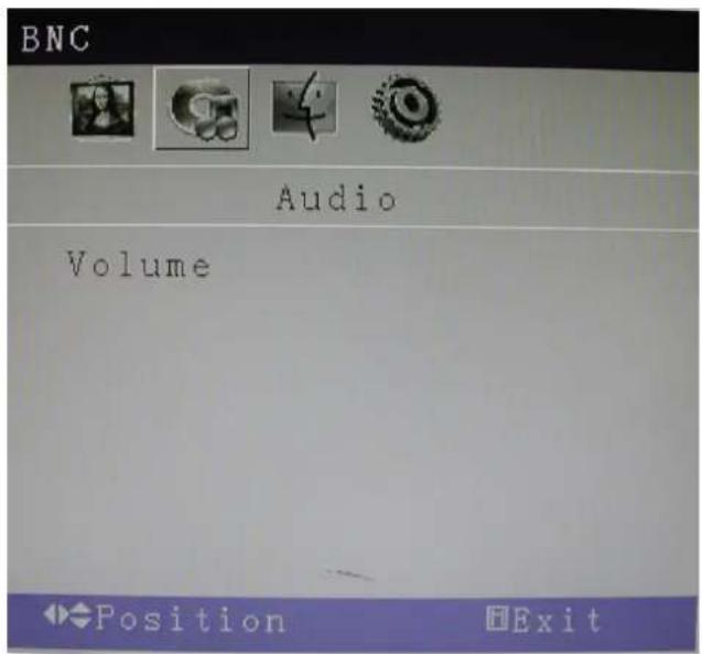
Adjustments
Volume: Increase or decrease the volume.
OSD Menu Functions and Settings
1. OSD setup under BNC input mode (continued)
C. OSD MENU
Press the MENU button to bring the menu on screen, and then Up / Down buttons to move left and right across the menu selections to highlight the OSD menu. Press the Menu (Source) button to enter the (highlighted) OSD sub menu.
Each additional press of the Menu/Source button moves the yellow highlighted sub-menu selection downward, moving from the bottom selection back to the top of the sub-menu. Pressing the Up / Down buttons will adjust the value of the highlighted item. Press the MENU button to save the values.
Press EXIT to exit the sub-menu, and go back to the main menu choices. Pressing the EXIT button while at the top level will close the menu and return to normal operations.
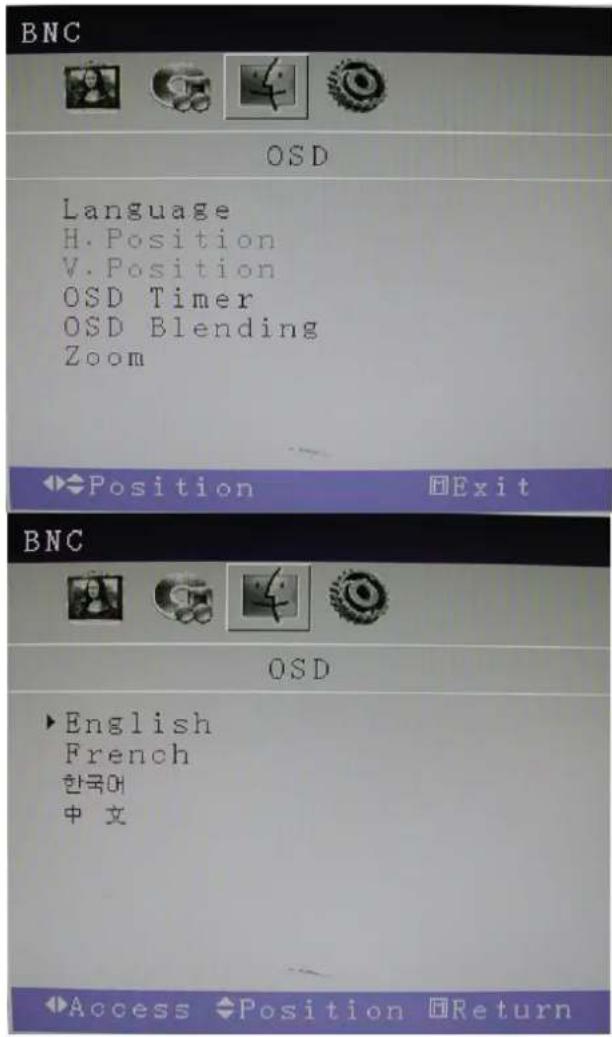
Adjustments
Language: There are four languages that you can choose from:
English, French, Korean, and Chinese.
H. Position: Adjusts the OSD Menu's Horizontal Position.
V. Position: Adjusts the OSD Menu's Vertical Position.
OSD Timer: The OSD Menu closes automatically after a set sleep time (between 1 and 60 seconds)
OSD Blending: Adjusts the brightness of the OSD Menu.
Zoom: Adjusts how much the OSD Menu is zoomed in.
OSD Menu Functions and Settings
1. OSD setup under BNC input mode (continued)
D. MISC
Press the MENU button to bring the menu on screen, and then Up / Down buttons to move left and right across the menu selections to highlight the MISC menu. Press the Menu (Source) button to enter the (highlighted) MISC sub menu.
Each additional press of the Menu/Source button moves the yellow highlighted sub-menu selection downward, moving from the bottom selection back to the top of the sub-menu. Pressing the Up / Down buttons will adjust the value of the highlighted item. Press the MENU button to save the values. Press EXIT to exit the sub-menu, and go back to the main menu choices.
Pressing the EXIT button while at the top level will close the menu and return to normal operations.
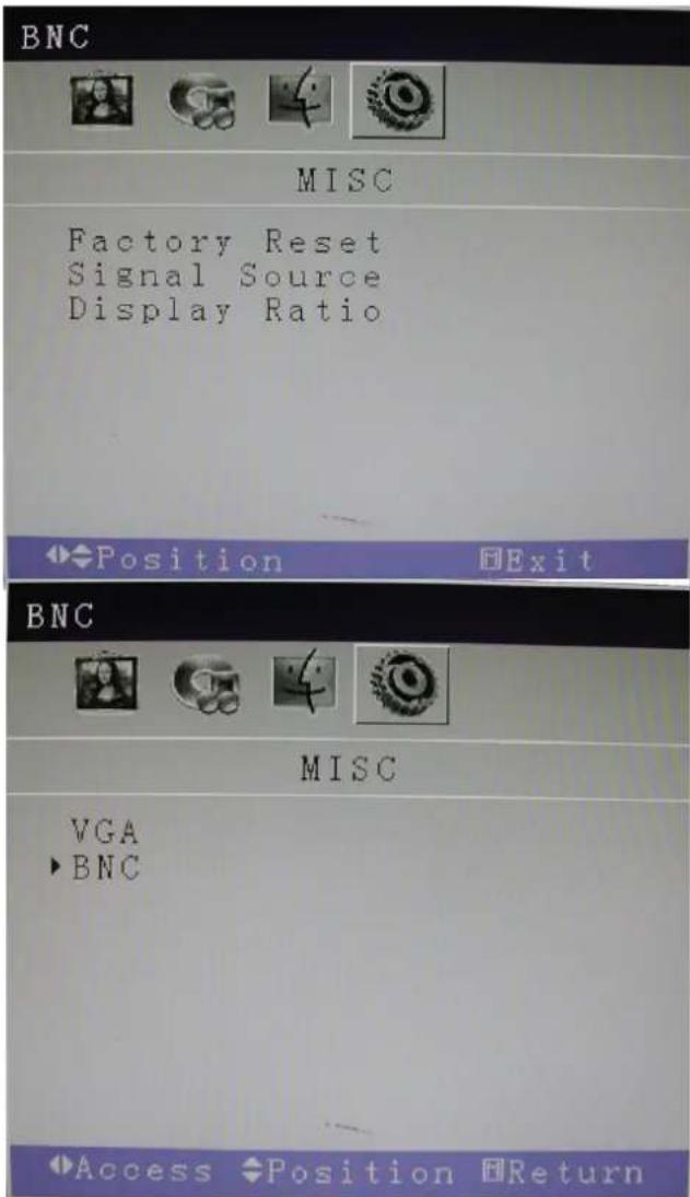
Adjustments
Factory Reset: Reset all settings back to default factory settings.
Signal Source: Choose between a BNC input or a VGA input source.
Display Ratio: Adjusts the dimensions of the display.
OSD Menu Functions and Settings
2. OSD setup under VGA input mode
A. COLOR MENU
Press the MENU button to bring the menu on screen, and then Up / Down buttons to move left and right across the menu selections to highlight the COLOR menu. Press the Menu (Source) button to enter the (highlighted) COLOR sub menu.
Each additional press of the Menu/Source button moves the yellow highlighted sub-menu selection downward, moving from the bottom selection back to the top of the sub-menu.
Pressing the Up / Down buttons will adjust the value of the highlighted item. Press the MENU button to save the values. Press EXIT to exit the sub-menu, and go back to the main menu choices. Pressing the EXIT button while at the top level will close the menu and return to normal operations.

Adjustments
Auto Color: Automatically adjusts the colors to the best color setting.
Contrast: Adjusts the contrast between light and dark areas of the picture.
Brightness: Adjusts the overall picture shading and brightness.
Color Temp: Adjusts the amount of red, green, and blue present in the image.
OSD Menu Functions and Settings
2. OSD setup under VGA input mode (continued)
B: IMAGE MENU
Press the MENU button to bring the menu on screen, and then Up / Down buttons to move left and right across the menu selections to highlight the IMAGE menu. Press the Menu (Source) button to enter the (highlighted) IMAGE sub menu.
Each additional press of the Menu/Source button moves the yellow highlighted sub-menu selection downward, moving from the bottom selection back to the top of the sub-menu.
Pressing the Up / Down buttons will adjust the value of the highlighted item. Press the MENU button to save the values. Press EXIT to exit the sub-menu, and go back to the main menu choices. Pressing the EXIT button while at the top level will close the menu and return to normal operations.
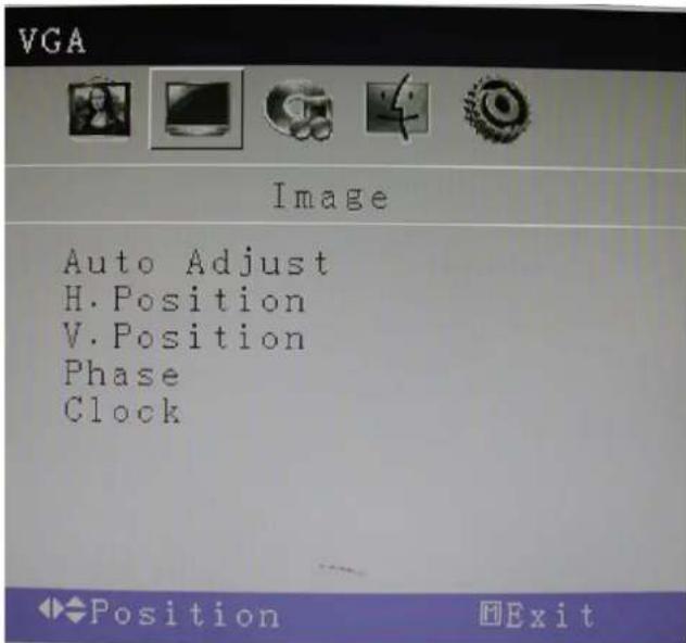
Adjustments
Auto Adjust: Automatically configures the Phase, Clock, Vertical, and Horizontal Position settings
H. Position: Adjusts the OSD Menu's Horizontal Position.
V. Position: Adjusts the OSD Menu's Vertical Position.
Phase: Adjusts the signal phase to improve sharpness when the image is fuzzy.
Clock: If the clock setting is not exactly the same as the DVR or computer, you may observe periodic vertical bars of video noise on your image. These noise bars are usually adjusted out when an Auto Adjust is performed. If the noise bars are still present, this setting can be adjusted manually.
OSD Menu Functions and Settings
2. OSD setup under VGA input mode (continued)
C. AUDIO MENU
Press the MENU button to bring the menu on screen, and then Up / Down buttons to move left and right across the menu selections to highlight the AUDIO menu. Press the Menu (Source) button to enter the (highlighted) AUDIO sub menu.
Each additional press of the Menu/Source button moves the yellow highlighted sub-menu selection downward, moving from the bottom selection back to the top of the sub-menu.
Pressing the Up / Down buttons will adjust the value of the highlighted item. Press the MENU button to save the values. Press EXIT to exit the sub-menu, and go back to the main menu choices. Pressing the EXIT button while at the top level will close the menu and return to normal operations.

Adjustments
Volume: Increase or decrease the volume.
OSD Menu Functions and Settings
2. OSD setup under VGA input mode (continued)
D. OSD MENU
Press the MENU button to bring the menu on screen, and then Up / Down buttons to move left and right across the menu selections to highlight the OSD menu. Press the Menu (Source) button to enter the (highlighted) OSD sub menu.
Each additional press of the Menu/Source button moves the yellow highlighted sub-menu selection downward, moving from the bottom selection back to the top of the sub-menu.
Pressing the Up / Down buttons will adjust the value of the highlighted item. Press the MENU button to save the values. Press EXIT to exit the sub-menu, and go back to the main menu choices. Pressing the EXIT button while at the top level will close the menu and return to normal operations.
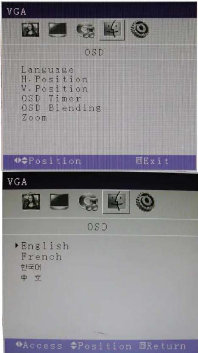
Adjustments
Language: There are four languages that you can choose from: English, French, Korean, and Chinese.
H. Position: Adjusts the OSD Menu's Horizontal Position.
V. Position: Adjusts the OSD Menu's Vertical Position.
OSD Timer: The OSD Menu closes automatically after a set sleep time (between 1 and 60 seconds)
OSD Blending: Adjusts the brightness of the OSD Menu.
Zoom: Adjusts how much the OSD Menu is zoomed in.
OSD Menu Functions and Settings
2. OSD setup under VGA input mode (continued)
E. MISC
Press the MENU button to bring the menu on screen, and then Up / Down buttons to move left and right across the menu selections to highlight the MISC menu. Press the Menu (Source) button to enter the (highlighted) MISC sub menu.
Each additional press of the Menu/Source button moves the yellow highlighted sub-menu selection downward, moving from the bottom selection back to the top of the sub-menu.
Pressing the Up / Down buttons will adjust the value of the highlighted item. Press the MENU button to save the values. Press EXIT to exit the sub-menu, and go back to the main menu choices. Pressing the EXIT button while at the top level will close the menu and return to normal operations.
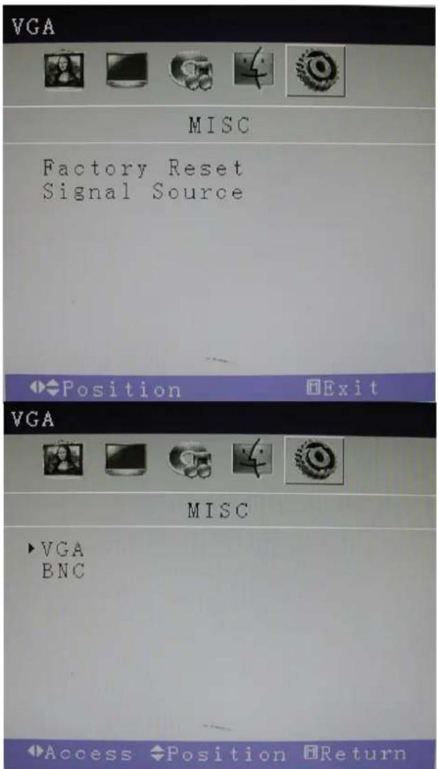
Adjustments
Factory Reset: Reset all settings back to default factory settings. Signal Source: Choose between a BNC input or a VGA input source.
Mounting Guide
Wall or Other Mounting with VESA Standard
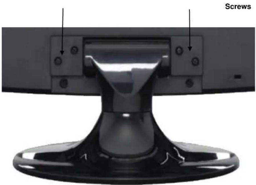
CAUTION: The wall mount must bear a minimum of five times the monitor's net weight. To mount your MONITOR to the wall or another surface, you need to purchase a VESA wall mount. Use four M4 x 8mm screws (not included) to attach the mount. The monitor mount VESA hole pattern is 100mm x 100mm. Note: Metric (M4 x 8 mm) is the type screw that should be used (do not use longer screws or the monitor may be damaged).
-
Before mounting the monitor, remove the base riser (vertical portion of the base) by removing the two screws at the top with a screwdriver. Then the base and the riser can be removed. In order to prevent losing the two screws, we suggest replacing the screws in their original holes.
-
Attach the VESA mount (100mm x 100mm) plate to the rear of the monitor and follow all of the instructions provided with the mount to complete the mounting process.
D-Sub Connector: PIN Assignments
▶ PIN ASSIGNMENTS
VGA interface(pins function)
| PIN | FUNCTION | PIN | FUNCTION |
| 1. | RED | 9. | +5V |
| 2. | GREEN | 10. | GND |
| 3. | BLUE | 11. | RSX |
| 4. | RTS | 12. | DDC-DATA |
| 5. | GND | 13. | H-SYNC |
| 6. | GND-R | 14. | V-SYNC |
| 7. | GND-G | 15. | DDC-CLOCK |
| 8. | GND-B | ||
ACCESSORIES

- Quick Installation Guide

- Power Cord
- VGA Cable

- User's Manual (available through re-saler)
Power Management
The power management feature of the monitor is comprised of three stages: On (Green Light), No Signal (Flashing Green Light), and Off (No Light).
| MODE | COLOR | MONITOR OPERATION |
| ON | Green | Normal Operation |
| NO SIGNAL | Flashing Green | No Signal |
| OFF | None | Power Off |
Specifications
| Model | M185LCBV4 | M215LCBV4 |
| Size | 18.5" LCD CCTV monitor | 21.5" LCD CCTV monitor |
| Aspect Ratio | 16:9 | |
| Resolution (H x V) | 1360 x 768 | 1920 x 1080 |
| Colors | 16.7M | |
| Viewing Angle | H: 170° V: 170° | |
| Viewing Lines | 420 TV Lines | |
| Contrast Ratio | 10000:1 (DCR) | |
| Response Time | 5ms | 2ms |
| 2D Comb Filter with De-interlace | Yes | |
| 2D Noise Reduction | Yes | |
| Brightness | 300cd/m2 | |
| Speakers | 2 each (2 watts) | |
| Composite Inputs / Outputs | BNC x 1 / BNC x 1 | |
| VGA | VGA x 1 | |
| Audio Inputs | Stereo PC | |
| Auto Adjustment | YES | |
| Wall Hanging | VESA Standard | |
| VESA Size | 100 x 100mm | |
| Stand | Plastic | |
| Bezel | Plastic | |
| OSD Language | English, French, Korean and Simplified Chinese | |
| Power Consumption | <20W | <30W |
| Power Supply | AC110~240V, 50/60 Hz | |
| Accessories | Power cord, Audio cable,VGA Cable and User's guide | |
| Packaging (L x D x W) | 19.6" x 17.8" x 7.5"498mm x 453mm x 191.6mm | 22.3" x 18.9" x 7.5"567mm x 482mm x 191.6mm |
| Dimension (L x D x W) | 17.5" x 13.8" x 5.43"444.2mm x 350.7mm x 138mm | 20.2" x 15.4" x 5.35"513.2mm x 391.7mm x 136mm |
| Gross Weight | 9.9lb (4.5Kg) | 12.1lb (5.5Kg) |
| Net Weight | 7.89lb (3.58Kg) | 9.7lb (4.4Kg) |
| Operating Temp | 32 °F - 122 °F (0 °C - 50 °C) | |
| Safety | FCC, CE, CB, RoHS | |
▶ NOTE : Technical specifications are subject to change without notice.
INSTRUCTION MANUAL.... 20


- User Manual M185LCBV4 and M215LCBV4
- Contents
- Safety Instructions
- CAUTION
- CAUTION TO SERVICE PERSONNEL
- EMISSION CHARACTERISTICS TESTED BY SEMKO
- Cautions
- FCC RF Interference Statement
- NOTE
- ▶ DOC COMPLIANCE NOTICE
- Connecting with External Equipment
- Key Control and Source Menu
- CONTROL KEYS/BUTTONS
- OSD Menu Functions and Settings
- OSD setup under BNC input mode
- COLOR MENU
- Adjustments
- OSD setup under BNC input mode (continued)
- AUDIO MENU
- OSD MENU
- MISC
- OSD setup under VGA input mode
- OSD setup under VGA input mode (continued)
- B: IMAGE MENU
- AUDIO MENU
- OSD MENU
- MISC
- Mounting Guide
- Wall or Other Mounting with VESA Standard
- D-Sub Connector: PIN Assignments
- ▶ PIN ASSIGNMENTS
- ACCESSORIES
- Power Management
- Specifications
Brand : Speco Technologies
Model : M185LCBV4
Category : Surveillance