CE-H21U11-S1 - Wi-Fi Router Siig - Free user manual and instructions
Find the device manual for free CE-H21U11-S1 Siig in PDF.

| Product Type | Wi-Fi Router |
| Brand | Siig |
| Model | CE-H21U11-S1 |
| Wireless Standard | IEEE 802.11b/g/n |
| Frequency Band | 2.4 GHz |
| Maximum Wireless Speed | 300 Mbps |
| Number of Antennas | 2 external fixed antennas |
| Ethernet Ports | 4 x 10/100 Mbps LAN, 1 x 10/100 Mbps WAN |
| USB Port | None |
| Power Supply | 12V DC, 1A |
| Power Consumption | 6W (typical) |
| Dimensions (W x D x H) | 200 x 130 x 30 mm |
| Weight | 300 g |
| Operating Temperature | 0°C to 40°C |
| Storage Temperature | -20°C to 70°C |
| Humidity | 10% to 90% non-condensing |
| Security | WPA/WPA2, WEP, MAC filtering |
| LED Indicators | Power, Internet, LAN, WLAN |
| Mounting | Desktop, wall-mountable |
| Package Contents | Router, power adapter, Ethernet cable, manual |
Frequently Asked Questions - CE-H21U11-S1 Siig
User questions about CE-H21U11-S1 Siig
0 question about this device. Answer the ones you know or ask your own.
Ask a new question about this device
Download the instructions for your Wi-Fi Router in PDF format for free! Find your manual CE-H21U11-S1 - Siig and take your electronic device back in hand. On this page are published all the documents necessary for the use of your device. CE-H21U11-S1 by Siig.
USER MANUAL CE-H21U11-S1 Siig
The HDMI Wireless Extender provides an easy way to extend HDMI signals wirelessly up to 80 meters.
Features and Benefits
- Sends video and audio from your HDMI source to TV/display wirelessly in 1080p quality
- Transmits content up to 80 meters LOS (Line of Sight) with no latency
- Supports 2.4GHz frequency with channel hopping – channel automatically changes when an interference is detected with other RF sources
- IR extender to control HDMI source device from the remote HDMI display end
- Complete kit with a Transmitter (TX) and Receiver (RX)
- HDMI output on Transmitter (TX) for a local TV/ display next to the source device
- Wall mountable
• LED status indicators for Power and Wireless connection
System Requirements
• PC or A/V devices with an available HDMI output port
- HDMI display
Package Contents
• HDMI Wireless Extender (Transmitter x1, Receiver x1)
- HDMI cables (2)
• Power adapters (5V/2A for Transmitter, 5V/1A for Receiver)
- IR blaster cable
- Screws for wall mount (4)
- Installation guide
Application
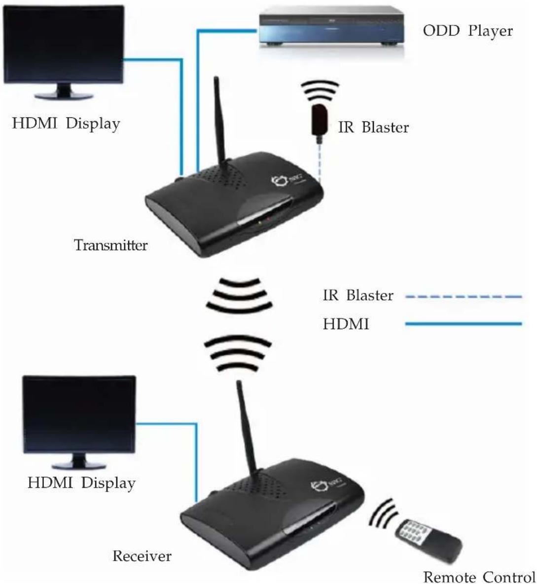
flowchart
graph TD
    A["Transmitter"] --> B["ODD Player"]
    B --> C["IR Blaster"]
    C --> D["Receiver"]
    D --> E["HDMI Display"]
    D --> F["HDMI Display"]
    D --> G["Remote Control"]
Figure 1: Application

text_image
Layout Transmitter Antenna Power LED Wireless LED IR Blaster HDMI In HDMI Out Power Button Power Jack Pairing ButtonFigure 2: Transmitter Layout
- Wireless LED: Red when the connection is established; flashing when searching for signal or disconnected
• Power LED: Red when the power adapter is connected; turns Green when powered on
• Antenna: Sends the signal to the receiver - Power Button: Turns the transmitter On/ Off
• Power Jack: Plug in the included 5V/2A power adapter here - Pairing Button: Press to connect to the receiver
- HDMI In: Connects to your HDMI source device (DVD player, etc) using the included HDMI cable
- HDMI Out: For local monitor; connects to your HDMI display using an HDMI cable (cable not included)
- IR Blaster: Plug in the included IR Blaster cable here. See IR Blaster Cable on page 4 for more information
Receiver

text_image
Receiver Antenna Power LED Wireless LED SIIG® Receiver Power Button Power Jack Pairing Button HDMI OutFigure 3: Receiver Layout
- Wireless LED: Red when the connection is established; flashing when searching for signal or disconnected
- Power LED: Red when the power adapter is connected; turns Green when powered on
- Antenna: Receives the signal from the transmitter
• Power Button: Turns the receiver On/ Off
• Power Jack: Plug in the included 5V/1A power adapter here - Pairing Button: Press to connect to the transmitter
- HDMI Out: Connect your HDMI display by using the included HDMI cable
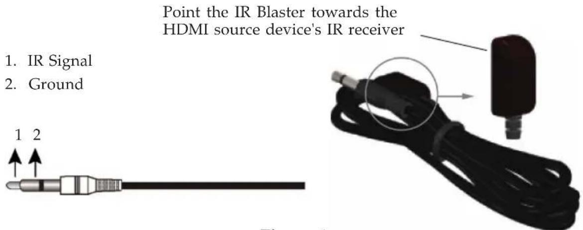
IR Blaster Cable (Optional)
Connect the IR blaster cable to the transmitter's IR Blaster connector to control the HDMI source device from the remote HDMI display end.
text_image
Point the IR Blaster towards the HDMI source device's IR receiver 1. IR Signal 2. Ground 1 2Figure 4
Note: IR cables can be found in the market. However, cables longer than 6ft may not work.
DC Power Jack
Refer to the table below for the specifications of the power adapter.
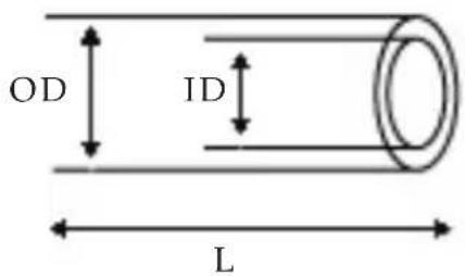
text_image
OD ID L| Outside diameter (OD) | Inside diameter (ID) | Plug length (L) | Negative / Positive |
| 5.3(mm) 2 | 2(mm) 11.5 | (mm) |  *Center pin for positive voltage and the outer shield for negative voltage *Center pin for positive voltage and the outer shield for negative voltage |
Table 1: Power Adapter Specifications
Hardware Installation
- Power off the displays, AV device and the extenders.
- Setup Transmitter: Connect your HDMI source to the HDMI In using the included HDMI cable and connect your HDMI display* to the HDMI Out using an HDMI cable (cable not included).
*Note: Connecting this HDMI display is optional. This HDMI display is needed only if you require local monitor support.
- Connect the IR Blaster Cable to the transmitter's IR blaster connector. Skip this step if IR transmission is not needed.
- Setup Receiver: Connect your HDMI display to the HDMI Out using the included HDMI cable.
- Plug the included 5V/2A power adapter into the transmitter's Power Jack; plug the 5V/1A power adapter into the receiver's Power Jack; plug both power adapters into reliable power sources.
- Press the power button of both transmitter and receiver and power on all connected devices.
- Make sure your HDMI displays are tuned to the correct HDMI input.
- Press and hold down the receiver's Pairing Button, when the Wireless LED flashes release the button.
- Press the transmitter's Pairing Button to establish connection. The HDMI Wireless Extender is ready to use.
Mount the Extenders on the Wall
- Drill the pilot holes.
- Insert the included screws into the wall. Leave approximately 1/8 inch for mounting the transmitter or receiver.
- Place the extender's mounting holes over the protruding screws and slide it down into position.

natural_image
Technical line drawing of a device with labeled components and directional arrows (no text or symbols)Figure 5
FAQ
Q1: The Power LED doesn't light up.
A1: Make sure the power adapters are properly inserted to the correct device (5V/2A for transmitter; 5V/1A for receiver) and plugged to reliable power sources.
Q2: No video is displayed on the TV screen.
A2:
- Make sure you are using the included HDMI cables to connect the displays to the transmitter's HDMI In and the receiver's HDMI Out.
• Make sure your HDMI displays are tuned to the correct HDMI input.
- Verify the Power LEDs and Wireless LEDs:
If the wireless LEDs are flashing red:
Move the transmitter closer to the receiver. The transmission range between the transmitter and the receiver should not exceed 80 meters (LOS-line of sight) transmission distance.
If the wireless LEDs are off:
- Make sure your HDMI displays, HDMI source device and the wireless extenders are powered on.
- Make sure you are using the included HDMI cables to connect your HDMI source device to the transmitter's HDMI In and your HDMI display to the receiver's HDMI Out.
Q3: No audio.
A3:
- Make sure the volume it turned up and not in "Mute" mode.
- Make sure the audio bit rate from the HDMI source device can be supported by the transmitter and receiver.
Q4: IR Blaster can't control source device.
A4: Make sure the transmitter is powered on and the IR Blaster is placed close to and pointed directly at the HDMI source device's IR receiver.
Blank Page
Blank Page
QUESTIONS? SIIG's Online Support has answers! Simply visit our web site at www.siig.com and click Support. Our online support database is updated daily with new drivers and solutions. Answers to your questions could be just a few clicks away. You can also submit questions online and a technical support analyst will promptly respond.
SIIG offers a 2-year manufacturer warranty with this product. This warranty covers the original purchaser and guarantees the product to be free of any defects in materials or workmanship for two (2) years from the date of purchase of the product.
SIIG will, at our discretion, repair or replace (with an identical product or product having similar features and functionality) the product if defective in materials or workmanship. This warranty gives you specific legal rights, and you may also have other rights which vary from state to state. Please see our web site for more warranty details.
If you encounter any problems with this product, please follow the procedures below.
A) If it is within the store's return policy period, please return the product to the store where you purchased it.
B) If your purchase has passed the store's return policy period, please follow these steps to have the product repaired or replaced.
Step 1: Submit your RMA request. Go to www.siig.com, click Support, then Request A Product Replacement to submit a request to SIIG RMA or fax a request to 510-657-5962. Your RMA request will be processed, if the product is determined to be defective, an RMA number will be issued.
Step 2: After obtaining an RMA number, ship the product.
- Properly pack the product for shipping. All software, cable(s) and any other accessories that came with the original package must be included.
- Clearly write your RMA number on the top of the returned package. SIIG will refuse to accept any shipping package, and will not be responsible for a product returned without an RMA number posted on the outside of the shipping carton.
- You are responsible for the cost of shipping to SIIG. Ship the product to the following address:
SIIG, Inc.
6078 Stewart Avenue
Fremont, CA 94538-3152, USA
RMA #:
- SIIG will ship the repaired or replaced product via Ground in the U.S. and International Economy outside of the U.S. at no cost to the customer.
Founded in 1985, SIIG, Inc. is a leading manufacturer of IT connectivity solutions (including Serial ATA and Ultra ATA Controllers, FireWire, USB, and legacy I/O adapters) that bridge the connection between Desktop/Notebook systems and external peripherals. SIIG continues to grow by adding A/V and Digital Signage connectivity solutions to our extensive portfolio. All centered around the distribution and switching of A/V signals over CAT5/6, these products include matrix switches, distribution amplifiers, extenders, converters, splitters, cabling, and more.
SIIG is the premier one-stop source of upgrades and is committed to providing high quality products while keeping economical and competitive prices. High-quality control standards are evident by one of the lowest defective return rates in the industry. Our products offer comprehensive user manuals, user-friendly features, and most products are backed by a lifetime warranty.
SIIG products can be found in many computer retail stores, mail order catalogs, and e-commerce sites in the Americas, as well as through major distributors, system integrators, and VARs.
PRODUCT NAME
HDMI Wireless Extender
FCC RULES: TESTED TO COMPLY WITH FCC PART 15, CLASS B OPERATING ENVIRONMENT: FOR HOME OR OFFICE USE
FCC COMPLIANCE STATEMENT:
This device complies with part 15 of the FCC Rules. Operation is subject to the following two conditions: (1) This device may not cause harmful interference, and (2) this device must accept any interference received, including interference that may cause undesired operation.
THE PARTY RESPONSIBLE FOR PRODUCT COMPLIANCE
SIIG, Inc.
6078 Stewart Avenue
Fremont, CA 94538-3152, USA
Phone: 510-657-8688
HDMI Wireless Extender is a trademark of SIIG, Inc. SIIG and the SIIG logo are registered trademarks of SIIG, Inc. Microsoft and Windows are registered trademarks of Microsoft Corporation. All other names used in this publication are for identification only and may be trademarks of their respective owners.