CE-H25Z11-S1 - Hi-Fi System Siig - Free user manual and instructions
Find the device manual for free CE-H25Z11-S1 Siig in PDF.

User questions about CE-H25Z11-S1 Siig
0 question about this device. Answer the ones you know or ask your own.
Ask a new question about this device
Download the instructions for your Hi-Fi System in PDF format for free! Find your manual CE-H25Z11-S1 - Siig and take your electronic device back in hand. On this page are published all the documents necessary for the use of your device. CE-H25Z11-S1 by Siig.
USER MANUAL CE-H25Z11-S1 Siig
natural_image
Red circular logo with a white abstract line design (no text or symbols)SIIG®
4x1 Multi-Video HDMI 2.0
Presentation Switcher
User Manual

text_image
4K HDR SHG® AirPlay Miracast HDMI 1 HDMI 2 USB-C Auto Select Display On Off LDVD FW
Preface
Read this user manual carefully before using the product. Pictures shown in this manual are for reference only. Different models and specifications are subject to real product.
This manual is only for operation instruction, please contact the local distributor for maintenance assistance. The functions described in this version were updated till November, 2019. In the constant effort to improve the product, we reserve the right to make functions or parameters changes without notice or obligation. Please refer to the dealers for the latest details.
FCC Statement
This equipment generates, uses and can radiate radio frequency energy and, if not installed and used in accordance with the instructions, may cause harmful interference to radio communications. It has been tested and found to comply with the limits for a Class B digital device, pursuant to part 15 of the FCC Rules. These limits are designed to provide reasonable protection against harmful interference in a commercial installation.
Operation of this equipment in a residential area is likely to cause interference, in which case the user at their own expense will be required to take whatever measures may be necessary to correct the interference.
Any changes or modifications not expressly approved by the manufacture would void the user's authority to operate the equipment.

text_image
CE FCC FEDERAL COMMUNICATIONS CONMISSION USA · NOISSIN -SAFETY PRECAUTIONS
To ensure the best from the product, please read all instructions carefully before using the device. Save this manual for further reference.
- Unpack the equipment carefully and save the original box and packing material for possible future shipment.
- Follow basic safety precautions to reduce the risk of fire, electrical shock and injury to persons.
- Do not dismantle the housing or modify the module. It may result in electrical shock or burn.
- Using supplies or parts not meeting the specifications of product may cause damage, deterioration or malfunction.
• Refer all servicing to qualified service personnel.
- To prevent fire or shock hazard, do not expose the unit to rain, moisture or install this product near water.
- Do not put any heavy items on the extension cable in case of extrusion.
- Do not remove the housing of the device as opening or removing housing may expose you to dangerous voltage or other hazards.
- Install the device in a place with fine ventilation to avoid damage caused by overheat.
- Keep the module away from liquids.
- Spillage into the housing may result in fire, electrical shock, or equipment damage. If an object or liquid falls or spills on to the housing, unplug the module immediately.
- Do not twist or pull by force ends of the optical cable. It can cause malfunction.
- Do not use liquid or aerosol cleaners to clean this unit. Always unplug the power to the device before cleaning.
- Unplug the power cord when left unused for a long period of time.
- Information on disposal for scrapped devices: do not burn or mix with general household waste, and please treat them as normal electrical wastes.
Table of Contents
1. Product Introduction....1
1.1 Features .... 1
1.2 Package List....2
2. Specification ....3
3. Panel Description....5
3.1 Front Panel ....5
3.2 Rear Panel....6
4. System Connection....7
4.1 Usage Precaution....7
4.2 System Diagram....7
4.3 Miracast/Airplay Connection....8
5. Front Panel Control....12
5.1 Manual-Switching 12
5.2 Auto-Switching....12
5.3 Display Control 12
5.4 EDID Setting....13
6. RS232 Control 14
6.1 RS232 Control Software....14
6.2 RS232 Command....16
6.2.1 System Control....16
6.2.2 Source Switching....16
6.2.3 CEC/RS232 Function Setting 17
6.2.4 Function Setting....18
6.2.5 Special Commands ....19
7. Firmware Upgrade....22
8. Troubleshooting & Maintenance ....23
9. Customer Service ....24
1. Product Introduction
Thanks for choosing the 4x1 Multi-Video HDMI 2.0 Presentation Switcher. The switcher is designed with one wireless Miracast/Airplay input, two HDMI inputs, one USB-C input and one HDMI output. It supports HDMI 2.0b, 4Kx2K@60Hz 4:4:4, HDR 10, Dolby Vision, and HDCP 2.2. In addition, there is smart built-in EDID setting can be selected by the 4-pin DIP switch on the front panel.
The switcher supports HDMI audio de-embedding. It also supports USB device extension by providing two type-B USB ports for host connection, and two type-A USB ports for USB devices such as camera, microphone, keyboard etc.
The switcher features multiple methods of control. When at the AUTO mode, the switcher will automatically switch to the first detected source device. The switcher can be manually controlled by the front panel buttons and RS232 command. CEC allows the display device can be controlled by the front panel buttons and RS232 and CEC commands.
1.1 Features
- 4x1 Multi-Video HDMI 2.0 Presentation Switcher with soft codec & wireless BYOD.
- Supports HDMI 2.0b, 4Kx2K@60Hz 4:4:4, HDR 10, Dolby Vision and HDCP 2.2.
- Wireless BYOD (Bring Your Own Device) capability via AirPlay and Miracast.
- Provide up to 60w charging, USB data (USB 3.0/2.0) and 4K video transmission on USB-C port.
- HDMI output audio can be de-embedded out via balanced analog audio port.
- Two type-B USB ports for host connection, and two type-A USB ports for USB devices like webcam, mic and keyboard.
• Supports video source auto-switching. - Smart EDID management.
- Front panel buttons trigger both CEC and RS232 commands for display control.
1.2 Package List
• 4x1 Multi-Video HDMI 2.0 Presentation Switcher
• 2x Mounting Ears with 4 Mounting Screws
- 4x Plastic Cushions
• 1x 5-pin Terminal Block
• 1x RS232 Cable (3-pin terminal block to DB9)
- 1x External Antenna
• 1x Power Adapter (24V DC 5A)
- 1x User Manual
Note: Please contact your distributor immediately if any damage or defect in the components is found.
- Specification
| Video | |
| Video Input | (1) AirPlay/Miracast, (2) HDMI, (1) USB-C |
| Video Input Connector | (1) External antenna connector, (2) Type-A female HDMI,(1) Type-C USB 3.0 |
| AirPlay/Miracast Input Resolution | Up to 4K@30Hz 4:4:4 |
| HDMI Input Resolution | Up to 4Kx2K@60Hz 4:4:4 HDR10, Dolby Vision |
| USB-C Input Resolution | Up to 4K@30Hz 4:4:4 |
| Video Output | (1) HDMI |
| Video Output Connector | (1) Type-A female HDMI |
| HDMI Output Resolution | Up to 4Kx2K@60Hz 4:4:4 HDR10, Dolby Vision |
| HDMI Standard | Up to HDMI 2.0b |
| HDCP Version | Up to HDCP 2.2 |
| Audio | |
| HDMI Embedded Audio Format | Supports Dolby Atmos, Dolby TrueHD, Dolby Digital Plus,Dolby Digital, DTS-X, DTS-HD Master Audio, DTS 5.1, 2 -8Ch PCM 32-192kHz 16-24 bits; 2-8Ch PCM 32-192kHz 16-24 bits |
| Balanced Analog Audio Output | (1) AUDIO OUT |
| Balanced Analog Audio Output Connector | (1) 5-pin terminal block |
| Frequency Response | 20Hz–20KHz, ±3dB |
| Max Output Level | 2.0Vrms ± 0.5dB |
| THD+N | < 0.05%, 20Hz – 20KHz bandwidth, 1KHz sine at 0dBFS level (or max level) |
| SNR | >80dB, 20Hz - 20KHz bandwidth |
| Crosstalk Isolation | <-80dB, 10KHz sine at 0dBFS level (or max level before clipping) |
| L-R Level Deviation | <0.05dB, 1KHz sine at 0dBFS level (or max level before clipping) |
| Output Load Capability | 1KΩ and higher (Supports 10x paralleled 10KΩ loads) |
| Noise Level | -80dB |
| Control | |
| Control port | (1) 4-pin DIP switch, (1) FW, (2) HOST (PC1&PC2), (2) DEVICES, (1) RS232 |
| Control Connector | (1) Micro-USB, (2) Type-B USB 3.0, (2) Type-A USB 3.0, (1) 3-pin terminal block |
| Network Connectivity | |
| WLAN Standards | IEEE 802.11ac |
| Band | 2.4 and 5GHz |
| Max. Wireless Coverage | ≤5m, environment dependent, reduce disturbance to increase transmission distance up to 10m |
| Max. Output Resolution | 4K/30Hz |
| Version | iOS 7 or above, MacOS, Android 4.0 or above, Windows8.1 or above. |
| General | |
| Operation Temperature | -5 ~ +55°C |
| Storage Temperature | -25 ~ +70°C |
| Relative Humidity | 10% ~ 90% |
| External Power Supply | Input: AC 100~240V, 50/60Hz; Output: 24V DC 5A. |
| Power Consumption | 85w (Max) |
| USB-C Power Charging | 60w (Max) |
| Dimension (W*H*D) | 238mm x 24.5mm x 135mm |
| Net Weight | 825g |
3. Panel Description
3.1 Front Panel
text_image
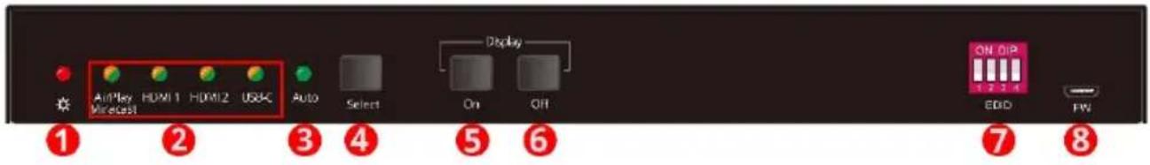
AirPlay Mirecast HDMI 1 HDMI2 USBC Auto Select Display On Off ON OIP 1 2 3 4 EDIO FW ① ② ③ ④ ⑤ ⑥ ⑦ ⑧① POWER LED: The LED illuminates red when power is applied.
② Four Input LEDs: The LED illuminates orange when there is video signal on its corresponding input channel and it will be off when there is no signal detected. It will illuminates green when the video signal is chosen as input source.
(3) AUTO LED: The LED illuminates green when the switcher is in auto-switching mode, and it will be off when exit the auto-switching mode.
④ SELECT: Press the button to select input source, or press and hold it at least 3 seconds to enable auto-switching mode. Please refer to the 5. Button Control for more details about switch rules.
⑤ DISPLAY ON: Press the button to send Display On command to turn on the display. Note that the RS232 command needs to be set by user. If an exception occurs at the AirPlay/Miracast input, press and hold the button at least 3 seconds to reset it.
⑥ DISPLAY OFF: Press the button to send Display Off command to turn off the display. Note that the RS232 command needs to be set by user.
⑦ EDID: 4-pin DIP switch for EDID setting.
⑧ FW: Micro USB port for firmware upgrade.
3.2 Rear Panel

text_image
1 2 3 4 5 6 7 8 9 HDMI 1 HDMI 2 USB-C HDMI Out Audio Out RS-232 PC 1 PG 2 USB Source USB 3.0 Devices DG 24V① Miracast/Airplay Input: Connect to the external antenna.
② HDMI1/HDMI2: Two type-A HDMI input ports to connect HDMI source devices.
③ USB-C: Type-C USB with charging capability to connect the Macbook or other device with SlimPort output.
Note: The USB 3.0 cable is recommended to be used to ensure optimal machine performance.
④ HDMI OUT: Type-A female HDMI output port to connect display device.
⑤ AUDIO OUT: 5-pin terminal block for audio de-embedding from HDMI output.
⑥ RS232: 3-pin terminal block to connect the RS232 control device (e.g. PC) or a third-party device to be controlled by RS232 commands.
⑦ USB source (PC1/PC2): Two type-B USB ports to connect HDMI PC1 and HDMI PC2 source devices individually.
⑧ USB 3.0 DEVICE (1&2): Two type-A USB ports to connect USB devices.
- When the HDMI PC1 is selected as video input source, the USB devices are switched to control the PC1 host.
- When the HDMI PC2 is selected as video input source, the USB devices are switched to control the PC2 host.
- When the USB-C PC3 is selected as video input source, the USB devices are switched to control the USB-C PC3.
⑨ DC 24V: DC connector for power adapter connection.
4. System Connection
4.1 Usage Precaution
- Make sure all components and accessories included before installation.
- System should be installed in a clean environment with proper temperature and humidity.
- All of the power switches, plugs, sockets, and power cords should be insulated and safe.
- All devices should be connected before power on.
4.2 System Diagram

flowchart
graph TD
    subgraph MacPods
        A["Laptop"] --> B["Router"]
        C["Laptop"] --> B
        D["MacBook"] --> B
        E["Projector"] --> B
        F["Amplifier"] --> B
        G["Keyboard"] --> B
        H["Mouse"] --> B
    end

    subgraph MacOS/iOS
        I["Android / Windows 8.1 or later version"] --> J["Miracast"]
        K["MacOS / iOS"] --> L["AptMap"]
    end

    B --> M["USB:"]
    B --> N["HDMI:"]
    B --> O["Audio:"]
    B --> P["USB-C:"]
    B --> Q["RS232:"]
4.3 Miracast/Airplay Connection
The device (e.g. MacOS/iOS, Android, Windows 8.1 or later Version) that support AirPlay/Miracast can be used as input source.
Here take iPhone, Samsung Android and Win10 Notebook as examples to introduce the connection of wireless projection.
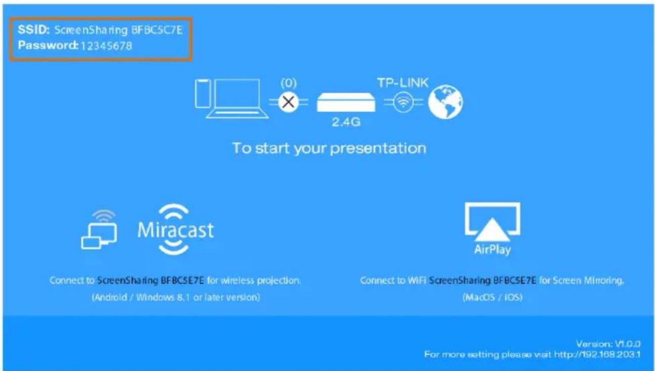
When switch to the Miracast/Airplay input by pressing the SELECT button, the Wi-Fi SSID and password will be showed on the display device.
SSID: ScreenSharing XXXXXX
Password: 12345678
text_image
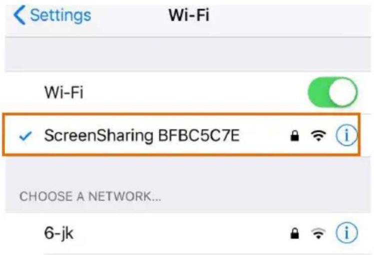
SSID: ScreenSharing BFBC5C7E Password: 12345678 To start your presentation Miracast Connect to ScreenSharing BFBC5E7E for wireless projection. (Android / Windows 8.1 or later version) Connect to WIFI ScreenSharing BFBC5E7E for Screen Minoring. (MacOS / iOS) AirPlay Version: V1.0.0 For more setting please visit http://192.168.203.1• Take iPhone as an example:
1) Connect the Apple iPhone to the Wi-Fi.
text_image
Settings Wi-Fi Wi-Fi ✓ ScreenSharing BFBC5C7E i CHOOSE A NETWORK... 6-jk2) Slide the iPhone screen to enter Control Center, and click the Screen Mirroring, and then click the SSID for screen mirroring.

text_image
Music Screen Mirroring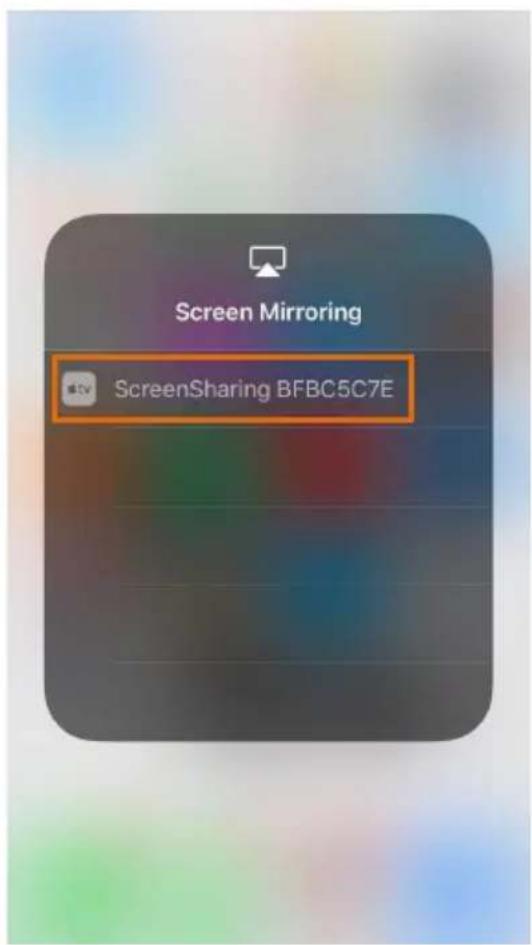
text_image
Screen Mirroring ScreenSharing BFBC5C7E• Take Samsung Android as an example:
Slide down the Android screen and click Smart View, then click the SSID for screen mirroring.

text_image
13:59 Fri 26 April WLAN Mobile data Bluetooth GPS Smart View Portrait Torch Mobile Hotspot Flight mode Mute NFC UHQ upscaler Calls Text messages Mobile data Always ask SIM 1 Turned off Data usage : 66.93 MB / 23.44 GB Phone Messages Settings Internet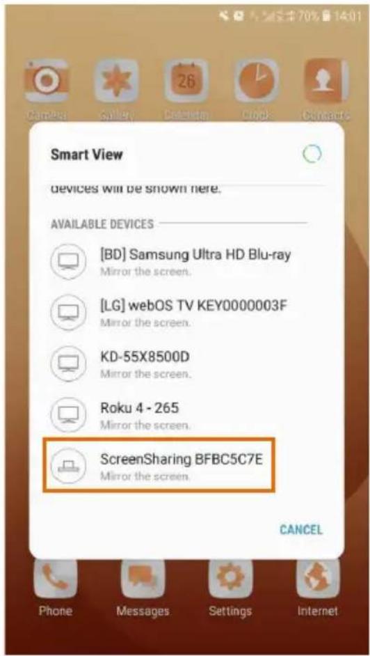
text_image
Smart View devices will be shown here. AVAILABLE DEVICES [BD] Samsung Ultra HD Blu-ray Mirror the screen. [LG] webOS TV KEY0000003F Mirror the screen. KD-55X8500D Mirror the screen. Roku 4 - 265 Mirror the screen. ScreenSharing BFBC5C7E Mirror the screen. CANCEL Phone Messages Settings Internet• Take Win10 Notebook as an example:
1) Press Winkey + P on keyboard, and then click Connect to a wireless display in the pop-up window.
2) Click the SSID for screen mirroring.
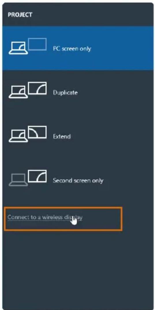
text_image
PROJECT PC screen only Duplicate Extend Second screen only Connect to a wireless display
text_image
CONNECT Searching for wireless display and audio devices Where is my device? Search [LG] webOS TV KEY0000003F Display Roku 4 - 265 Display [BD] Samsung Ultra HD Blu-ray Display KD-43X8500F Display ScreenSharing BFBC5C7E Display KD-55X8500D Display Projecting to this PC Find other types of devices5. Front Panel Control
5.1 Manual-Switching
When the switcher is in the manual switching mode, press the SELECT button repeatedly to cycle through the four video inputs, and the corresponding source LED illuminates green immediately.
5.2 Auto-Switching
Press and hold the SELECT button at least three seconds to enable auto-switching, and the AUTO LED turns green.
When in the AUTO mode, the switcher will switch according to the following rules:
- The switcher will switch to the first active input starting at AirPlay/Miracast to USB-C.
- New input: The switcher will automatically select the new input once detecting a new input.
- Reboot: If power is restored to the switcher, it will automatically reconnect the input before shutdown.
- Source removed: When an active source is removed, the switcher will switch to the first active input starting at AirPlay/Miracast input to USB-C.
- In auto mode, the input source also can be switched by the manual switching steps.
- Press and hold the SELECT button at least three seconds again can exit AUTO mode, but the input source will not be changed.
Note that the AirPlay/Miracast is not an active input when there is no screen sharing device connection.
5.3 Display Control
- Manual Control: Press the DISPLAY ON/OFF buttons on the front panel to simultaneously send RS232 and CEC commands to turn on/off the display device.
- Auto Control: When detecting a video input signal (5V or TMDS), automatically send CEC and RS232 commands to turn on the display device. When not detecting any video signal within the setting time (default 10mins), automatically send RS232 and CEC commands to turn off the display device.
The RS232 command can be set by sending commands, please refer to the 6.2.5 Special Command for more details.
5.4 EDID Setting
The Extended Display Identification Data (EDID) is used by the source device to match its video resolution with the connected display. The DIP switch on the front panel can be used to set the EDID to a fixed value to ensure the compatibility in video resolution. The switch represents "0" when in the lower (OFF) position, and it represents "1" while putting the switch in the upper (ON) position.

text_image
ON OFF ON DIP 1 2 3 4 1 0Note: The EDID DIP switch only used for setting the EDID of HDMI source device, and the USB-C source device will automatically gains the EDID of display device.
| Switch Status | Video Resolution | Audio Format |
| 0000 | EDID Pass-through | |
| 0001 | 1280x720@60Hz | Stereo |
| 0010 | 1920x1080@60Hz DVI | - |
| 0011 | 1920x1080@60Hz 8bit | Stereo |
| 0100 | 1920x1080@60Hz 8bit | High Definition |
| 0101 | 1920x1200@60Hz 8bit | Stereo |
| 0110 | 3840x2160@30Hz 8bit | Stereo |
| 0111 | 3840x2160@30Hz 8bit | High Definition |
| 1000 | 3840x2160@30Hz 8bit HDR | Stereo |
| 1001 | 3840x2160@60Hz Deep Color | Stereo |
| 1010 | 3840x2160@60Hz Deep Color HDR | High Definition |
| Switch Status | EDID | Note |
| 1011 | User-defined EDID 1 | The five user-defined EDID can be uploaded by sending RS232 command“#UPLOAD_USER_EDID [PARAM]”, please refer to the chapter6.2.4 Function Setting for more details. |
| 1100 | User-defined EDID 2 | |
| 1101 | User-defined EDID 3 | |
| 1110 | User-defined EDID 4 | |
| 1111 | User-defined EDID 5 | |
- Stereo: LPCM 2CH.
- High Definition Audio: LPCM 8Ch, AC-3 6Ch, DTS 5.1, Dolby Digital5.1, DTS-HD7.1, Dolby TrueHD 7.1
• Deep Color: 8bit, 10bit, 12bit
6. RS232 Control
Connect the RS232 port to control device (e.g. PC) with RS232 cable. The switcher can be controlled by sending RS232 commands.
6.1 RS232 Control Software
• Installation: Copy the control software file to the control PC.
- Uninstallation: Delete all the control software files in corresponding file path.
Basic Settings:
Connect the switcher with all input devices and output devices needed, then to connect it with a PC which is installed with RS232 control software. Double-click the software icon to run this software.
Here take the software CommWatch.exe as example:

CommWatch.exe
The main view is shown as below:
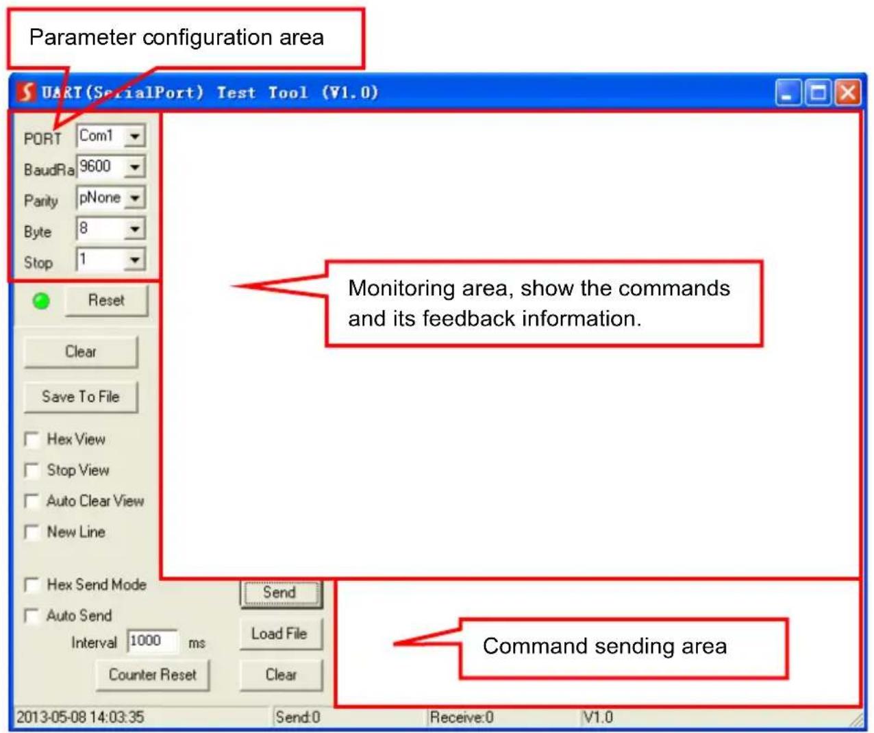
text_image
Parameter configuration area UART (SerialPort) Test Tool (V1.0) PORT Com1 BaudRia 9600 Parity pNone Byte 8 Stop 1 Reset Clear Save To File Hex View Stop View Auto Clear View New Line Hex Send Mode Send Auto Send Interval 1000 ms Counter Reset Load File Clear 2013-05-08 14:03:35 Send:0 Receive:0 V1.0Please set the parameters of COM number, bound rate, data bit, stop bit and the parity bit correctly, and then you are able to send command in command sending area.
6.2 RS232 Command
Communication protocol: RS232 Communication Protocol
Baud rate: 9600
Data bit: 8
Stop bit: 1
Parity bit: none
6.2.1 System Control
The ending mark of command is "
| Command Description | Command & Feedback Example | |
| #GET_FIRMWARE_VERSION | Get the firmware version. @V1.0.0 | |
| #FACTORY_RESET | Restore to factory defaults. | @FACTORY_RESET |
| #REBOOT | System reboot. | @REBOOT |
| #HELP [PARAM] | Get the command details.[PARAM]=Null; Get all command list.[PARAM]=Any command; Get the English description and usage of the command. | #HELP SET_AV |
| @SELECT VIDEO AND AUDIO INPUT PORT#SET_AV PARAM1PARAM=A,PC1,PC2,PC3A - Airplay/MiracastPC1 - HDMI1PC2 - HDMI2PC3 - TYPE-C | ||
| #SET_RST_WIRELESS | Reset Airplay/Miracast power | @RESET WIRELESS DEVICE |
| #SET_KEYPAD_LOCK 1 | Lock front panel buttons. | #SET_KEYPAD_LOCK 1 |
| #SET_KEYPAD_LOCK 0 | Unlock front panel buttons (Default). #SET_KEYPAD_LOCK 0 | |
| #GET_KEYPAD_LOCK | Get the locking status of the front panel buttons. | @KEYPAD_LOCK 1 |
6.2.2 Source Switching
| Command Description | Command & Feedback Example | |
| #SET_AV A | Select the input source: Airplay/Miracast (Default). | @AV Airplay/Miracast |
| #SET_AV PC1 | Select the input source: PC1. | @AV PC1 |
| #SET_AV PC2 | Select the input source: PC2. | @AV PC2 |
| #SET_AV PC3 | Select the input source: PC3. | @AV PC3 |
| #GET_AV | Get the current input source. | @AV PC1 |
| #SET_AUTO_SWITCH 0 | Disable auto-switching mode. | @AUTO_SWITCH 0 |
| #SET_AUTO_SWITCH 1 | Enable auto-switching mode. | @AUTO_SWITCH 1 |
| #GET_AUTO_SWITCH | Get the auto-switching status. | @AUTO_SWITCH 1 |
6.2.3 CEC/RS232 Function Setting
The ending mark of command is "
| Command Function | Command & Feedback Example | |
| #SET_SYNCACT_CEC 1 | Enable the function of automatically sending CEC commands.When detecting video input signal or not detecting any video signal, the switcher will automatically send the corresponding CEC command to control the display device. | @SYNCACT_CEC 1 |
| #SET_SYNCACT_CEC 0 | Disable the function of automatically sending CEC commands. | @SYNCACT_CEC 0 |
| #GET_SYNCACT_CEC | Get the function setting status of automatically sending CEC commands. | @SYNCACT_CEC 1 |
| #SET_SYNCACT_RS232 1 | Enable the function of automatically sending RS232 commands.When detecting video input signal or not detecting any video signal, the switcher will automatically send the corresponding RS232 command to control the display device. | @SYNCACT_RS232 1 |
| #SET_SYNCACT_RS232 0 | Disable the function of automatically sending RS232 commands. | @SYNCACT_RS232 0 |
| #GET_SYNCACT_RS232 | Get the function setting status of automatically sending RS232 commands. | @SYNCACT_RS232 1 |
| #SET_DISPLAY 1 | Power on display device (Simultaneously sending CEC and RS232 commands to display device). | @DISPLAY 1 |
| #SET_DISPLAY 0 | Power off display device (Simultaneously sending CEC and RS232 commands to display device). | @DISPLAY 0 |
6.2.4 Function Setting
The ending mark of command is "
| Command Description | Command & Feedback Example | |
| #SET_OFF_CNT 1 | Set the number of sending DISPLAY OFF command to 1 time. | @OFF_CNT 1 |
| #SET_OFF_CNT 2 | Set the number of sending DISPLAY OFF command to 2 times. | @OFF_CNT 2 |
| #GET_OFF_CNT | Get the number of sending DISPLAY OFF command. | @OFF_CNT 1 |
| #SET_OFF_DELAY [PARAM] | Set the delay time of sending DISPLAY OFF command to [PARAM].[PARAM]=5~100 (1=100ms). | #SET_OFF_DELAY 5 |
| @OFF_DELAY 5 | ||
| #GET_OFF_DELAY | Get the delay time of sending DISPLAY OFF command. | @OFF_DELAY 5 |
| #SET_OUTPUT_HDCP [PARAM] | Set the HDCP mode of output port to [PARAM]. [PARAM]=1~3:1 - ACTIVE2 - ON3 - OFF | #SET_OUTPUT_HDCP 1 |
| @OUTPUT_HDCP 1 | ||
| #GET_OUTPUT_HDCP | Get the HDCP mode of output port. | @OUTPUT_HDCP 1 |
| #SET_SW_HDCP_MODE [PARAM] | Switch the input ports to support HDCP2.2 status. [PARAM]= 0/1.0 - UNSUPPORT HDCP2.21 - SUPPORT HDCP2.2 | #SET_SW_HDCP_MODE 1 |
| @SW_HDCP_MODE 1 | ||
| #GET_SW_HDCP_MODE | Get the HDCP2.2 status of input ports. | @SW_HDCP_MODE 1 |
| #UPLOAD_USER_EDID [PARAM] | Upload the user-defined EDID [PARAM].PARAM = 1 ~ 51 - User-defined EDID 12 - User-defined EDID 23 - User-defined EDID 34 - User-defined EDID 45 - User-defined EDID 5 | #UPLOAD_USER_EDID 1 |
| @USER_EDID 1 READY PLEASE SEND EDID DATA IN 10S OK/ERROR | ||
| When the command applied, system prompts to upload the EDID file (.bin).Operation will be cancelled in 10 seconds. | ||
| #SET_DTIME [PARAM1]:[PARAM2] | When not detecting video input signal, set the auto power-off time of display device to [PARAM1]: [PARAM2]. The default time is 10 minutes.[PARAM1]=0~30 minutes.[PARAM2]=0~1800 seconds. | #SET_DTIME 1:30 |
| @DTIME 1:30 | ||
| #GET_DTIME | Get the auto power-off time of display device. | @DTIME 30:0 |
6.2.5 Special Commands
Note: The below commands don't need ending mark.
| Command Description | Command & Feedback Example | |
| #SET_ON_[PARAM1]_[PARAM2]:XXXX | Set the ASCII RS232 command XXXX to be sent to control the third-party device when the DISPLAY ON button is pressed.[PARAM1] = 00~06 (Baud Rate)00 - 11520001 - 5760002 - 3840003 - 1920004 - 960005 - 480006 - 2400[PARAM2] = 00~99. The delay time of sending command.XXXX: Any ASCII code (up to 48 bytes). | #SET_ON_05_30:1234567 |
| @BAUDRATE: 4800@DELAY TIME: 30 s@DISPLAY ON TOSEND:1234567 | ||
| #SET_H_ON_[PARAM1]_ [PARAM2]:XX XX | Set the HEX RS232 command XX XX to be sent to control the third-party device when the DISPLAY ON button is pressed.[PARAM1] = 00~06 (Baud Rate)00 - 11520001 - 5760002 - 3840003 - 1920004 - 960005 - 480006 - 2400[PARAM2] = 00~99. The delay time of sending command.XX XX: Any HEX code (0-9, A-F; up to 20 bytes. It must have a blank between 2 different XX). | #SET_H_ON_05_30:3132 33 34 35 |
| @BAUDRATE: 4800@DELAY TIME: 30 s@DISPLAY ON HEX TO SEND:31 32 33 34 35 | ||
| #SET_OF_[PARAM1][PARAM2]:XXXX | Set the ASCII RS232 command XXXX to be sent to control the third-party device when the DISPLAY OFF button is pressed.[PARAM1] = 00~06 (Baud Rate)00 - 11520001 - 5760002 - 3840003 - 1920004 - 960005 - 480006 - 2400[PARAM2] = 00~99. The delay time of sending command.XXXX: Any ASCII code (up to 48 bytes). | #SET_OF_05_30:ABCD EFG |
| @BAUDRATE: 4800@DELAY TIME: 30 s@DISPLAY OFF TO SEND:ABCDEFG | ||
| #SET_H_OF_[PARAM1]_ [PARAM2]:XX XX | Set the HEX RS232 command XX XX to be sent to control the third-party device when the DISPLAY OFF button is pressed.[PARAM1] = 00~06 (Baud Rate)00 - 11520001 - 5760002 - 3840003 - 1920004 - 960005 - 480006 - 2400[PARAM2] = 00~99. The delay time of sending command.XX XX: Any HEX code (0-9, A-F; up to 20 bytes. It must have a blank between 2 different XX). | #SET_H_OF_05_30:4142 43 44 45 |
| @BAUDRATE: 4800@DELAY TIME: 30 s@DISPLAY OFF HEX TO SEND:41 42 43 44 45 |
7. Firmware Upgrade
Please follow the steps as below to upgrade firmware by the FW port on the rear panel:
1) Prepare the latest upgrade file (.bin) and rename it as "FW_MERG.bin" on PC.
2) Power off the switcher, and connect the FW port of switcher to the PC with USB cable.
3) Power on the switcher, and then the PC will automatically detect a U-disk named of "BOOTDISK".
4) Double-click the U-disk, a file named of "READY.TXT" would be showed.
5) Directly copy the latest upgrade file (.bin) to the "BOOTDISK" U-disk.
6) Reopen the U-disk to check the filename "READY.TXT" whether automatically becomes "SUCCESS.TXT", if yes, the firmware was updated successfully, otherwise, the firmware updating is fail, the name of upgrade file (.bin) should be confirm again, and then follow the above steps to update again.
7) Remove the USB cable after firmware upgrade.
8) After firmware upgrade, the switcher should be restored to factory default by sending command.
- Troubleshooting & Maintenance
| Problems | Potential Causes | Solutions |
| Output image with white noise. | Bad quality of the connecting cable | Try another high-quality cable. |
| Fail or loose connection | Make sure the connection is good. | |
| No output image when switching | No signal at the input / output end. | Check with oscilloscope or multimeter if there is any signal at the input/ output end. |
| Fail or loose connection. | Make sure the connection is good. | |
| The switcher is broken. | Send it to authorized dealer for repairing. | |
| POWER indicator doesn’t work or no respond to any operation | Fail connection of power cord. | Make sure the power cord connection is good. |
| Cannot control the device by control device (e.g. a PC) through RS232 port | Wrong RS232 communication parameters. | Type in correct RS232 communication parameters. |
| Broken RS232 port. | Send it to authorized dealer for checking. |
Note: If your problem still remaining after following the above troubleshooting steps, please contact your local dealer or distributor for further assistance.
9. Customer Service
The return of a product to our Customer Service implies the full agreement of the terms and conditions hereinafter. There terms and conditions may be changed without prior notice.
1) Warranty
The limited warranty period of the product is fixed three years.
2) Scope
These terms and conditions of Customer Service apply to the customer service provided for the products or any other items sold by authorized distributor only.
3) Warranty Exclusion
- Warranty expiration.
- Factory applied serial number has been altered or removed from the product.
- Damage, deterioration or malfunction caused by:
√ Normal wear and tear.
√ Use of supplies or parts not meeting our specifications.
√ No certificate or invoice as the proof of warranty.
√ The product model showed on the warranty card does not match with the model of the product for repairing or had been altered.
√ Damage caused by force majeure.
√ Servicing not authorized by distributor.
√ Any other causes which does not relate to a product defect.
- Shipping fees, installation or labor charges for installation or setup of the product.
4) Documentation
Customer Service will accept defective product(s) in the scope of warranty coverage at the sole condition that the defeat has been clearly defined, and upon reception of the documents or copy of invoice, indicating the date of purchase, the type of product, the serial number, and the name of distributor.
Support
For more info or tech support
http://www.siig.com/support