HD-P61R1U - Television JVC - Free user manual and instructions
Find the device manual for free HD-P61R1U JVC in PDF.

User questions about HD-P61R1U JVC
0 question about this device. Answer the ones you know or ask your own.
Ask a new question about this device
Download the instructions for your Television in PDF format for free! Find your manual HD-P61R1U - JVC and take your electronic device back in hand. On this page are published all the documents necessary for the use of your device. HD-P61R1U by JVC.
USER MANUAL HD-P61R1U JVC
Projection Television Users Guide
For Models:
HD-P61R1U
HD-P70R1U
natural_image
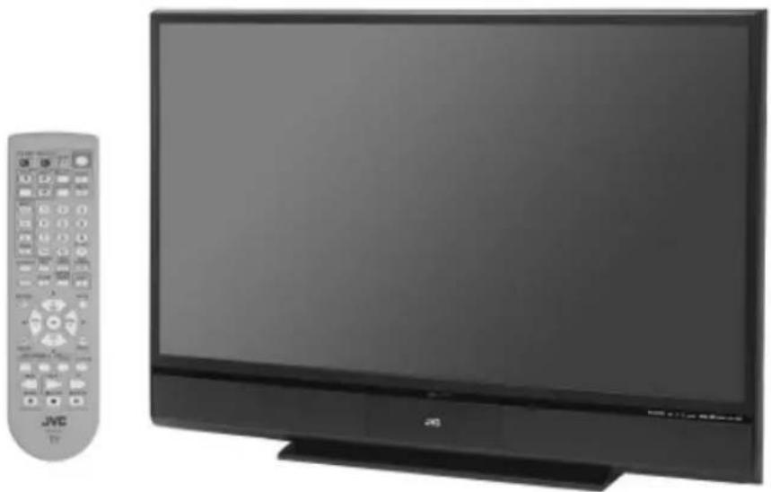
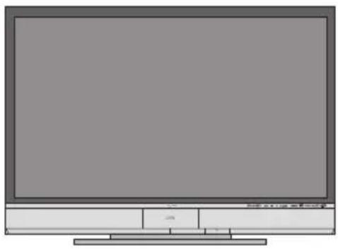
Exterior view of a JMC TV set with a remote control (no visible text or symbols on the main subject)Illustration of HD-P70R1U and RM-C14G
Important Note:
In the spaces below, enter the model and serial number of your television (located at the rear of the television cabinet). Staple your sales receipt or invoice to the inside cover of this guide. Keep this user's guide in a convenient place for future reference. Keep the carton and original packaging for future use.
Model Number:
Serial Number:
Important Safety Precautions
CAUTION:
CAUTION
RISK OF ELECTRIC SHOCK DO NOT OPEN

To reduce the risk of electric shock. Do not remove cover (or back). No user serviceable parts inside. Refer servicing to qualified service personnel.

The lightning flash with arrowhead symbol, within an equilateral triangle is intended to alert the user to the presence of uninsulated “dangerous voltage” within the product’s enclosure that may be of sufficient magnitude to constitute a risk of electric shock to persons.
The exclamation point within an equilateral triangle is intended to alert the user to the presence of important operating and maintenance (servicing) instructions in the literature accompanying the appliance.
WARNING: TO PREVENT FIRE OR SHOCK HAZARDS, DO NOT EXPOSE THIS TV SET TO RAIN OR MOISTURE.
CAUTION: TO INSURE PERSONAL SAFETY, OBSERVE THE FOLLOWING RULES REGARDING THE USE OF THIS UNIT.
- Operate only from the power source specified on the unit.
- Avoid damaging the AC plug and power cord.
- Avoid Improper installation and never position the unit where good ventilation is unattainable.
- Do not allow objects or liquid into the cabinet openings.
- In the event of trouble, unplug the unit and call a service technician. Do not attempt to repair it yourself or remove the rear cover.
Changes or modifications not approved by JVC could void the warranty.
* When you don't use this TV set for a long period of time, be sure to disconnect both the power plug from the AC outlet and antenna for your safety.
* To prevent electric shock do not use this polarized plug with an extension cord, receptacle or other outlet unless the blades can be fully inserted to prevent blade exposure.

NOTICE (for USA)
This product has a High Intensity Discharge (HID) lamp that contains a small amount of mercury. It also contains lead in some components. Disposal of these materials may be regulated in your community due to environmental considerations. For disposal or recycling information, please contact your local authorities, or the Electronics Industries Alliance: http://www.eiae.org
This product incorporates copyright protection technology that is protected by U.S. patents and other intellectual property rights. Use of this copyright protection technology must be authorized by Macrovision, and is intended for home and other limited viewing uses only unless otherwise authorized by Macrovision. Reverse engineering or disassembly is prohibited.
Some pay-per-view programs may be licensed from producers as "view-only" programs.
These are copyrighted programs and may not be copied or reproduced for any purpose without the express written permission of the copyright owner.
For best viewing, if your VCR is "ON", turn the TV/VCR switch to the "TV" position.
IMPORTANT SAFETY INSTRUCTIONS
1) Read these instructions.
2) Keep these instructions.
3) Heed all warnings.
4) Follow all instructions.
5) Do not use this apparatus near water.
6) Clean only with dry cloth.
7) Do not block any ventilation openings. Install in accordance with the manufacturer's instructions.
8) Do not install near any heat sources such as radiators, heat registers, stoves, or other apparatus (including amplifiers) that produce heat.
9) Do not defeat the safety purpose of the polarized or grounding-type plug. A polarized plug has two blades with one wider than the other. A grounding type plug has two blades and a third grounding prong. The wide blade or the third prong are provided for your safety. If the provided plug does not fit into your outlet, consult an electrician for replacement of the obsolete outlet.
10) Protect the power cord from being walked on or pinched particularly at plugs, convenience receptacles, and the point where they exit from the apparatus.
11) Only use attachments/accessories specified by the manufacturer.
12) Use only with a cart, stand, tripod, bracket, or table specified by the manufacturer, or sold with the apparatus. When a cart is used, use caution when moving the cart/apparatus combination to avoid injury from tip-over.

natural_image
Silhouette of a person pushing a ladder inside a circular frame with a diagonal line (no text or symbols)13) Unplug this apparatus during lightning storms or when unused for long periods of time.
14) Refer all servicing to qualified service personnel. Servicing is required when the apparatus has been damaged in any way, such as power-supply cord or plug is damaged, liquid has been spilled or objects have fallen into the apparatus, the apparatus has been exposed to rain or moisture, does not operate normally, or has been dropped.
15) Apparatus shall not be exposed to dripping or splashing and no objects filled with liquids, such as vases, shall be placed on the apparatus.
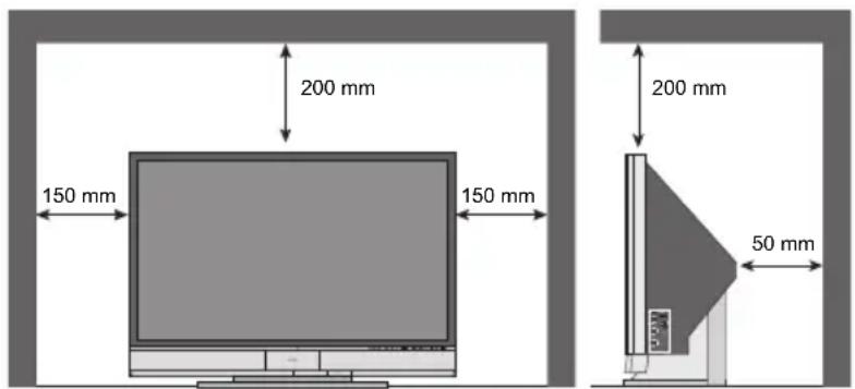
16) Avoid improper installation and never position the unit where good ventilation is impossible. When installing this TV, distance recommendations must be maintained between the set and the wall, as well as inside a tightly enclosed area or piece of furniture. Keep to the minimum distance guidelines shown for safe operation.
text_image
200 mm 150 mm 150 mm 200 mm 50 mm17) Cautions for installation
— Do not tilt the TV towards the left or right, or towards the back.
— Install the TV in a corner on the floor so as to keep cords out of the way.
— The TV will generate a slight amount of heat during operation. Ensure that sufficient space is available around the TV to allow satisfactory cooling.
FCC Notice:
Note: This equipment has been tested and found to comply with the limits for a Class B digital device, pursuant to Part 15 of the FCC Rules. These limits are designed to provide reasonable protection against harmful interference in a residential installation. This equipment generates, uses and can radiate radio frequency energy and, if not installed and used in accordance with the instructions, may cause harmful interference to radio communications. However, there is no guarantee that interference will not occur in a particular installation. If this equipment does cause harmful interference to radio or television reception, which can be determined by turning the equipment off and on, the user is encouraged to try to correct the interference by one or more of the following measures:
– Reorient or relocate the receiving antenna.
– Increase the separation between the equipment and receiver.
- Connect the equipment into an outlet on a circuit different from that to which the receiver is connected.
- Consult the dealer or an experienced radio/TV technician for help.
Warnings
Caring for the Cabinet
Normally, light dusting with a soft, non-scratching duster will keep your TV clean.
If you wish to wipe down the television, first unplug it. Then wipe gently with a soft cloth, slightly moistened with water. You can add a few drops of mild liquid detergent to the water to help remove spots of oily dirt.
- DO NOT allow liquid to enter the TV through the ventilation slots.
• DO NOT use strong or abrasive cleaners on the TV. - DO NOT spray liquids or cleaners directly on the TV's surface.
- DO NOT rub or scrub the TV harshly. Wipe the set gently with a soft cloth.
Caring for the Screen
The screen is treated with an electrostatic-proof coating. When it gets dirty, wipe it gently with a soft cloth. If the screen is very dirty, wipe it down with a cloth dipped in a diluted kitchen cleaner and thoroughly wrung-out. Then wipe immediately after with a clean, dry cloth.
Do not apply alcohol, organic solvents (like acetone), acidic or alkaline cleansers to the screen. These will remove the coating layer and cause discolorations.
Do not push or hit the screen. This could cause scratches on the screen surface and image distortions.
Warnings
Thank you for purchasing JVC's model HD-P61R1U or HD-P70R1U HDTV-ready projection television which uses the high-quality HD-ILA projection system. This is one of the highest quality and most technologically advanced televisions available today. It is recommended that you read this instruction manual before using your television in order to learn about it's many features. Cautions related to the safe use of the device and important information which will help you to be able to use this device for a long time is in the Appendix. Once again, thank you for purchasing this television and please enjoy using it.
In order to use the television for a long time
This television uses a lamp to project the picture onto the screen. Before using this television, please read the safety cautions and information about this television which are summarized below.
1. When the power is turned on, the warming up commences
This television uses a lamp to project the picture onto the screen. Once the lamp has warmed up, you can enjoy the pictures at their full brightness. What happens when the power is turned on is explained below. Immediately after the power is turned on, since the lamp has not had time to warm up, the picture is displayed only dimly on the screen. As the lamp warms up, the picture becomes brighter. It takes approximately one minute for the lamp to warm up to it's normal operating temperature. There are 2 LED indicators on the front panel of the television that can be used as a guide. When the POWER button is pressed, the LAMP/PROGRAM LED indicator blinks in orange for approximately 1 minute at approximately every 2 seconds, and then goes out.
Note: It is impossible to turn the power off during this period. After 1 or more minutes have passed, you can turn off the power.
2. Cooling the inside of the television and the lamp
Cooling is also performed while the television is being shut down.
When the POWER button is pressed to turn off the power, the following operations are performed. When the television is turned off, the picture on the screen disappears. Once the screen is dark, cooling is performed for approximately 90 seconds. When the cooling is being performed, the LAMP/PROGRAM LED indicator on the front panel blinks in orange at approximately every 3 seconds. The television can not be operated while the cooling is being performed. After the cooling has been performed for 90 seconds, the power is turned off. Do not remove the electrical plug until after the cooling process has completed. If the electrical plug is removed before the cooling process has completed, the internal circuits and lamp may overheat leading to the life of the lamp being shortened and the possibility of malfunctions.
Do not block the ventilation holes.
Do not block the ventilation holes while the power is turned on. Do not block the air intake holes behind the speaker grills.
3. The lamp is a consumable item
Replace the lamp when it has blown or when the picture becomes dark. The lamp is a user replaceable item. The lamp must be recycled. For a detailed explanation on how to recycle the lamp, refer to the Appendix and the instructions that are included with the replacement lamp kit. The life of the lamp changes depending on the atmospheric temperature and altitude in which the TV is being used.
Warnings
4. The television requires a lot of electrical power
It is recommended that the television is connected directly to the wall socket, and not to another device. When connecting the television to a wall socket that is being used by another device, or when using an extension cord, be careful not to exceed the electrical capacity of the socket.
Do not turn the power on and off repeatedly in a short amount of time.
It subjects the television and the lamp to stress and may lead to malfunctions and the life of the lamp being shortened.
5. The screen is made of plastic
Handle the screen very carefully as it can scratch easily. Do not rub, hit or press on it with any hard objects. When the screen is dirty, gently wipe it with a soft cloth. Refer to the Appendix for details on how to clean the screen.
6. Caution! Warm air from the air ducts
This unit has an air duct for cooling. The duct will blow warm air while the television is operating. When placing the television, make sure not to locate it too close to wallpaper. The warm air could cause the color of the wallpaper to change. Also, take care to keep children and pets away from the warm air ducts. Long exposure to the warm air from the ducts could cause a minor burn.
7. Caution! Moving this television
When lifting this television, Do not hold by the screen frame. Holding the screen frame could cause it to detach, causing the television to fall.
8. Do not replace the lamp immediately after use
The lamp becomes extremely hot during use. If the lamp is touched immediately after use before it has a chance to cool down, there is a danger of burns. Be careful when handling the lamp.
9. Do not touch the lamp glass
If the lamp is used when there is dirt from fingers on the lamp glass, there is a possibility of the lamp breaking. Be careful not to touch the lamp glass.
10. ILA element characteristics
Do not project still pictures or pictures that have still segments for a long period of time. The still parts of the picture may remain on the screen. This is a characteristic of ILA elements and not a malfunction. The picture will disappear over time.
11. Condensation
When a heater is turned on or the television is moved from a cold place to a hot place, droplets of water may form on the lamp and screen. This is called condensation. If the television is used while this condensation is still present, the picture may seem distorted, and the inside of the screen may become dirty. In this case, wait until the condensation has gone before using the television.
12. Do not open the rear cabinet of this television
This television has a DIGITAL-IN terminal. Opening up the rear cabinet will violate the copyright of the program or software shown on the television. Please do not open the rear cabinet.
13. Usable Time
Do not keep the TV on for more than 24 hours consecutively. There is a possibility of the life of the lamp being shortened.
Table of Contents
Important Safety Precautions . 2
Warnings 5
Quick Setup ..... 10
Unpacking your TV 10
TV Models 12
TV Remote Control 14
Getting Started 15
The Remote Control ..... 15
Connecting Your Devices ..... 16
Interactive Plug In Menu ..... 30
Remote Programming ..... 33
Setting CATV, VCR and DVD Codes . . . 33
CATV or Satellite Codes ..... 33
VCR Codes 34
DVD Codes 35
Search Codes 36
Onscreen Menus ..... 37
Using the Guide 37
Onscreen Menu System ..... 38
Initial Setup 40
Auto Tuner Setup 40
Channel Summary 41
Channel Label 42
V-Chip 43
Set Lock Code 49
Language 50
Closed Caption 50
Auto Shut Off 53
XDS ID 53
Noise Muting 53
Front Panel Lock 54
V1 Smart Input 54
Video Input Label 55
Position Adjustment 56
Power Indicator 56
Video-1 Monitor Out 57
TV Speaker 57
Audio Out 57
Digital-In 58
Digital-In Audio 58
Center CH Input 59
Picture Adjust ..... 60
Picture Settings 60
Adjust Picture Settings 60
Color Temperature 60
Color Management 61
Dynamic Gamma 61
Smart Picture 61
Digital VNR 62
MPEG NR 62
Reset 62
Sound Adjust ..... 63
Sound Settings 63
Adjust Sound Settings 63
Reset 63
Clock/ Timers ..... 64
Set Clock 64
On/Off Timer 65
Lamp Reset 66
Button Functions ..... 67
Multi Screen Function 67
Twin 67
Index 68
Freeze 68
Swap 68
Select 68
Power 69
Number Buttons 69
Tune 69
Input 69
TheaterPro D6500K 69
Return+/TV 70
Sound 70
Video Status 71
Natural Cinema 71
Muting 72
Sleep Timer 72
ML/MTS 72
Display 73
C.C. 73
Channel +/- 73
Volume +/- 73
Favorite 74
Aspect 75
Aspect Ratios 75
Aspect Ratios in PC Mode ..... 75
Menu 76
OK 76
Back 76
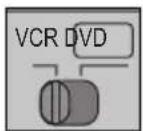
TV/CATV Slide Switch 77
VCR/DVD Slide Switch 77
VCR Buttons 77
DVD Buttons 77
Light 77
Digital Setup 78
Digital Setup 78
Antenna Level 78
Digital Sound 79
Aspect Ratio 79
Cable Card Application ..... 80
i.LINK Auto Play 80
Software Update 80
Digital Button Functions . . . 81
Digital CH D/A (Digital/Analog) ..... 81
Sub Channel 81
i.LINK Menu 82
Controller 82
Device 83
Timer 84
Reservation 84
Timer Edit 85
Guide 86
Media Card Viewer ..... 87
Readable Media Card 87
Supported Card Media 87
How to insert Media Card ..... 88
How to operate Media Card Viewer ..... 89
Photo 90
Video 90
File 91
Operation Notes 92
Specifications 93
OSD Information ..... 94
Weak Signal 94
No Program 94
Invalid Signal 94
Cable Card Information . . . . 95
Cable Card Connection ..... 95
Appendices ..... 96
Troubleshooting 96
Changing The Lamp 98
Replacement Lamp Kit ..... 98
Lamp Messages 99
How To Replace The Lamp ..... 99
Warning LED Messages ..... 101
Service 102
Specifications 103
Quick Setup
Unpacking your TV
Thank you for your purchase of a JVC Color Television. Before you begin setting up your new television, please check to make sure you have all of the following items. In addition to this guide, your television box should include:
Television x 1
natural_image
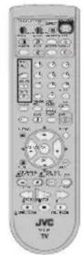
Front view of a flat-screen television displaying (no visible text or symbols)Remote Control x 1
text_image
JVC TVAA
Batteries x 2
Note: Your television and/or remote control may differ from the examples illustrated here.
Two Way Splitter x 1
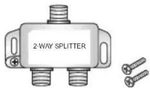
text_image
2-WAY SPLITTERRF Cables x 2

natural_image
Simple line drawing of a butterfly with wings, no text or symbols presentQuick Setup
Unpacking your TV
Once you have unpacked your television, the next step is to connect it to your antenna/cable or satellite system and to connect the audio/video devices you want to use with your television. To make these connections you will use plugs like the ones illustrated below.
Coaxial Cables

Used to connect an external antenna or cable TV system to your TV.
S-Video Cable

Used to make video connections with S-Video VCRs, Camcorders and DVD players.
Component Cables Composite Cables Audio Cables

Used to connect audio/video devices like VCRs, DVD players, stereo amplifiers, game consoles, etc.
AV CompuLink Cable

natural_image
Black and white illustration of a soldering iron (no text or symbols)Used to connect JVC AV CompuLink capable components for an automated home theater.
We recommend that before you start using your new television, you read your entire User's Guide so you can learn about your new television's many great features. If you're anxious to start using your television right away, a quick setup guide follows on the next few pages.
Quick Setup
TV Models
NOTE: Before you connect your television to another device, please refer to the proper diagrams for your specific TV and remote. These will help assist you in understanding how to connect your television to another device, as well as use the remote to set up your television.
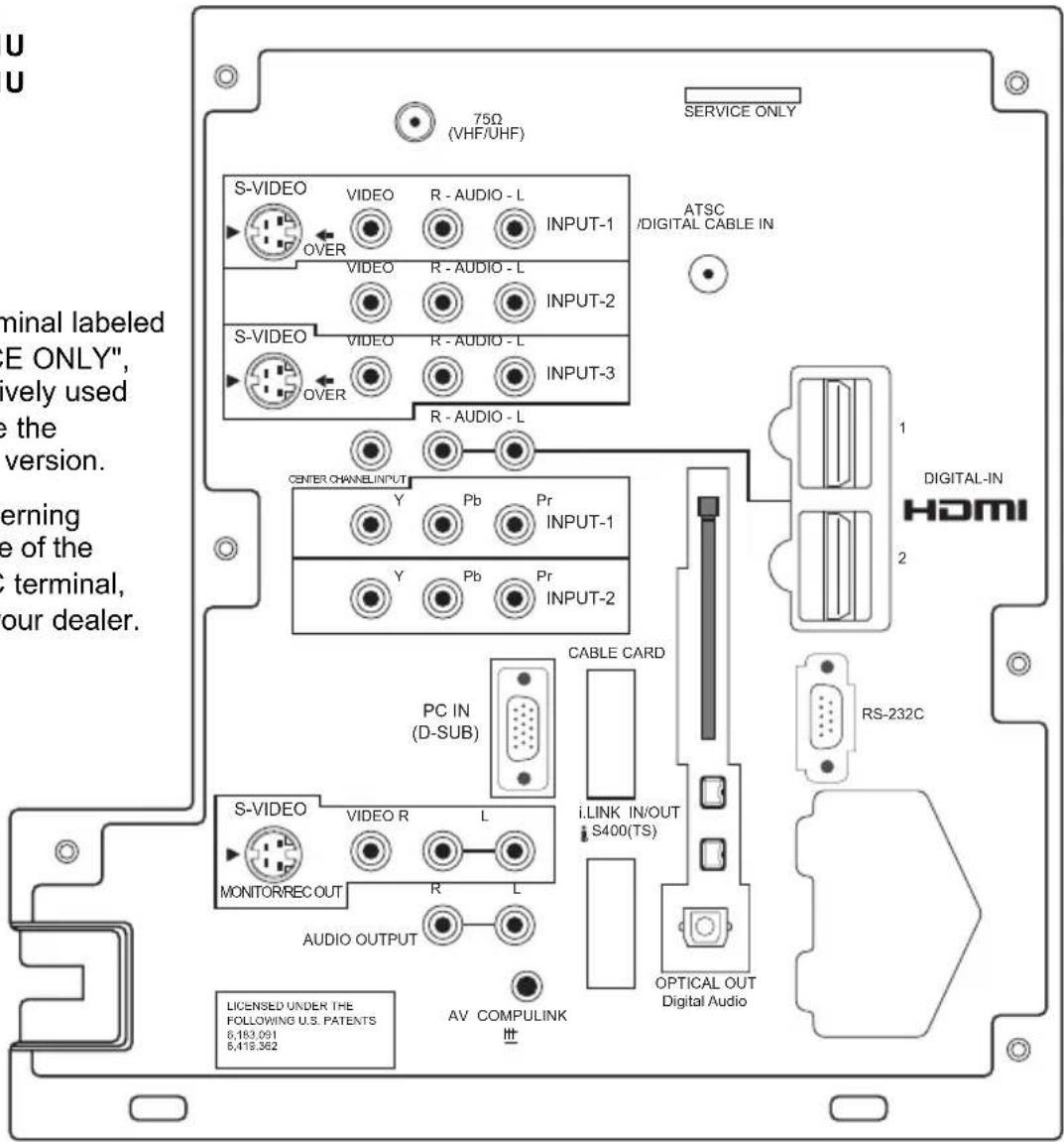
Rear Panel Diagram
MODELS: HD-P61R1U HD-P70R1U
Note:
- The terminal labeled "SERVICE ONLY", is exclusively used to update the software version.
• For governing the usage of the RS-232C terminal, consult your dealer.
text_image
U U 75Ω (VHF/UHF) SERVICE ONLY S-VIDEO VIDEO R - AUDIO - L INPUT-1 OVER VIDEO R - AUDIO - L INPUT-2 S-VIDEO VIDEO R - AUDIO - L INPUT-3 OVER R - AUDIO - L CENTER CHANNEL INPUT Y Pb Pr INPUT-1 Y Pb Pr INPUT-2 PC IN (D-SUB) CABLE CARD i-LINK IN/OUT S400(TS) S-VIDEO VIDEO R L MONITORREC OUT R L AUDIO OUTPUT AV COMPULINK LICENSED UNDER THE FOLLOWING U.S. PATENTS 6,183.091 6,419.362 ATSC /DIGITAL CABLE IN DIGITAL-IN HDMI RS-232C OPTICAL OUT Digital AudioQuick Setup
TV Models
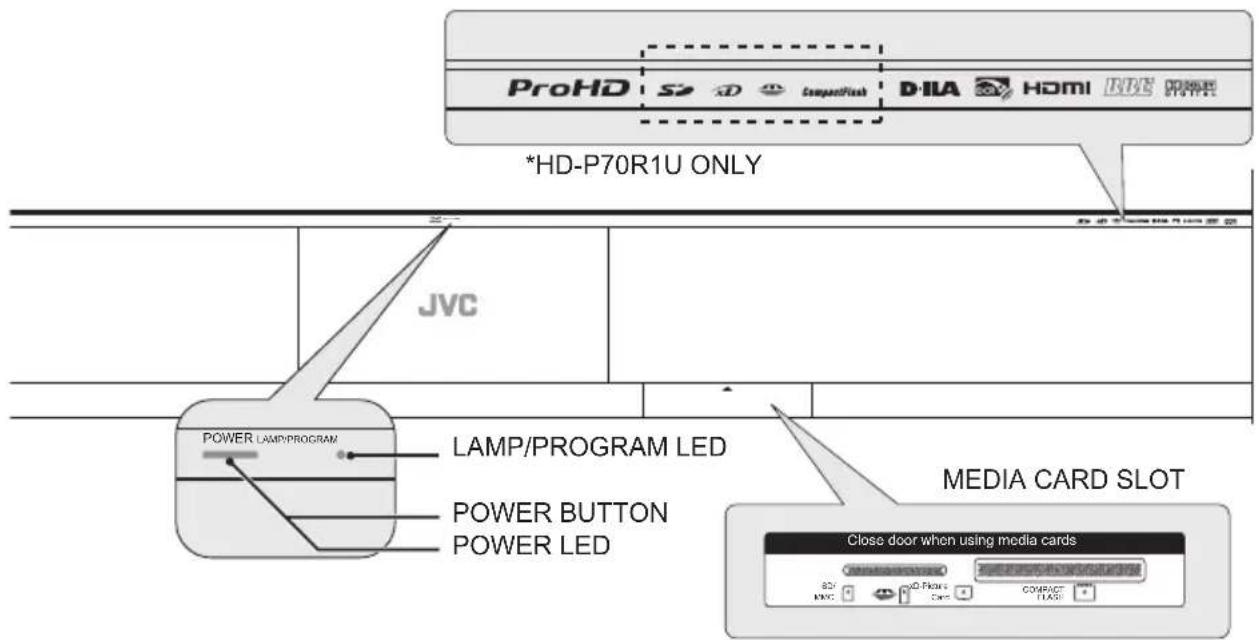
Front Panel Diagram
text_image
ProHD S2 D CompuntFlash D-ILA HDMI RDE POWER *HD-P70R1U ONLY JVC POWER LAMP/PROGRAM LAMP/PROGRAM LED POWER BUTTON POWER LED MEDIA CARD SLOT Close door when using media cards 80% MWC 40% Flow Cass COMPACT FLAGMODELS: HD-P61R1U, HD-P70R1U
- For information on the LED, see page 101.
• Media Card Slot is for HD-P70R1U ONLY. To open the door, gently pull the tab on the door.
Side Panel Diagram
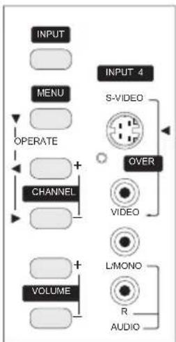
flowchart
graph TD
    A["INPUT"] --> B["MENU"]
    B --> C["OPERATE"]
    C --> D["CHANNEL"]
    D --> E["VOLUME"]
    E --> F["L/MONO"]
    F --> G["R"]
    F --> H["AUDIO"]
    I["INPUT 4"] --> J["S-VIDEO"]
    J --> K["OVER"]
    K --> L["VIDEO"]
    L --> M["L/MONO"]
MODELS: HD-P61R1U, HD-P70R1U
text_image
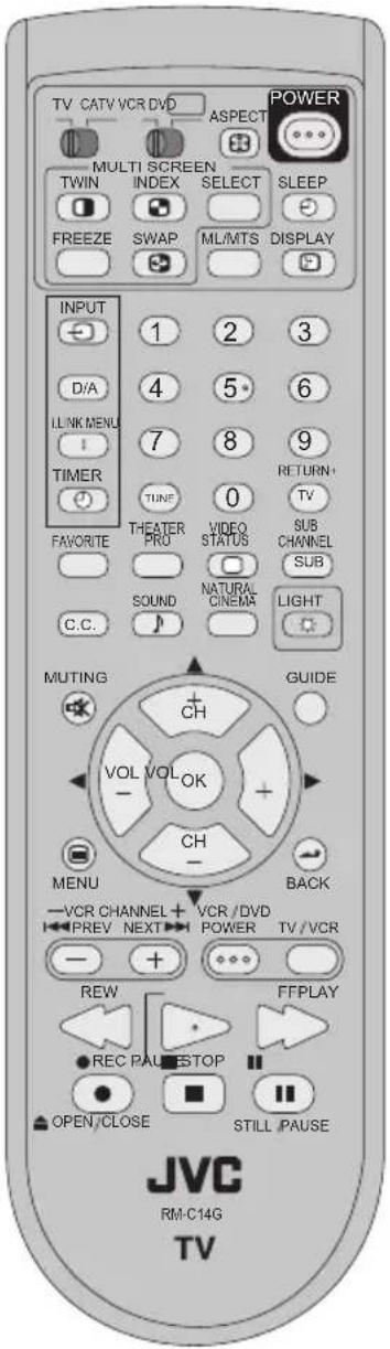
TV CATV VCR DVD ASPECT POWER MULTI SCREEN TWIN INDEX SELECT SLEEP FREEZE SWAP ML/MTS DISPLAY INPUT 1 2 3 D/A 4 5 6 LINK MENU 7 8 9 TIMER TUNE 0 RETURN+ TV FAVORITE THEATER VIDEO SUB CHANNEL PRO STATUS SUB SOUND NATURAL LIGHT C.C. LIGHT MUTING CH GUIDE VOL VOL OK CH MENU BACK -VCR CHANNEL + VCR /DVD PREV NEXT POWER TV /VCR - + ... REW FFPLAY REC PAU STOP OPEN CLOSE STILL PAUSE JVC RM-C14G TVRM-C14G
MODELS:
HD-P61R1U
HD-P70R1U
- For information on remote control buttons, see pages 67 - 77 and 81 - 86.
- i.LINK MENU, TIMER, SUB CHANNEL and GUIDE buttons are for digital channels. If your TV is connected to an ATSC antenna or Digital Cable, you can use these buttons.
Getting Started
These quick setup pages will provide you, in three easy steps, with the basic information you need to begin using your new television right away. If you have questions, or for more detailed information on any of these steps, please consult other sections of this manual.
Step 1 – The Remote Control
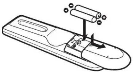
Before you can operate your remote control, you first need to install the batteries (included).
Slide the cover on the back of the remote down towards the bottom of the remote control. Insert two batteries (included) carefully noting the “+” and “-” markings, placing the “-” end in the unit first. Slide the cover back into place.
text_image
Diagram of a remote control device with labeled components and directional arrows indicating movement or operation.When you change the batteries, try to complete the task within three minutes. If you take longer than three minutes, the remote control codes for your VCR, DVD, and/or cable box/satellite receiver may have to be reset. See pages 33 - 36.
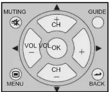
Key Feature Buttons
The four key feature buttons at the center of the remote can be used for basic operation of the television. The top and bottom buttons will scan forward and back through the available channels. To move rapidly through the channels using JVC's Hyperscan feature, press and hold CH+ or CH-. The channels will zip by at a rate of five channels per second. The right and left buttons will turn the volume up or down. These buttons are also marked with four arrows and are used with JVC's onscreen menu system. To use the onscreen menus, press the MENU button.
text_image
MUTING CH VOL VOLOK CHANGE MENU CH BACKBasic Operation
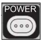
Turn the television on and off by pressing the POWER button at the top right corner of the remote. The POWER LED will light blue. If this is the first time you are turning on the TV, the interactive plug-in menu appears.
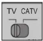
• Make sure the TV/CATV switch is set to TV. Move the switch to CATV only if you need to operate a cable box.
- Slide the VCR/DVD selector switch to VCR to control a VCR. Slide to DVD to control a DVD player. Please see pages 33 to 36 for instructions on programming your remote control to operate a cable box, VCR or DVD player.
Note:
- If the lamp replacement message appears when you turn the television ON, see page 99.
Step 2 – Connecting Your Devices
To make these connections, you will use plugs like the ones illustrated below.
S-Video Cable

Used to make video connections with S-Video VCRs, Camcorders and DVD players.
Component Cables Composite Cables Audio Cables

Used to connect audio/video devices like VCRs, DVD players, stereo amplifiers, game consoles, etc.
Notes:
• These connections are examples.
- After you are finished connecting your devices, plug the power cord into the nearest power outlet and turn on the TV.
- If you follow these diagrams and the television does not work properly, contact your local cable operator.
- To connect a DVD player, see VCR Connection. A DVD player is optional
- If you have a satellite television system, refer to the satellite TV manual.
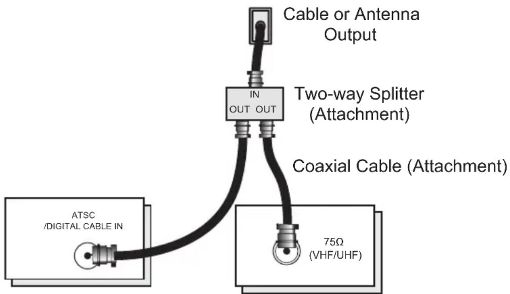
No VCR Connection
flowchart
graph TD
    A["ATSC /DIGITAL CABLE IN"] --> B["Two-way Splitter (Attachment)"]
    B --> C["Cable or Antenna Output"]
    B --> D["Coaxial Cable (Attachment)"]
    B --> E["75Ω (VHF/UHF)"]
TV Rear Panel
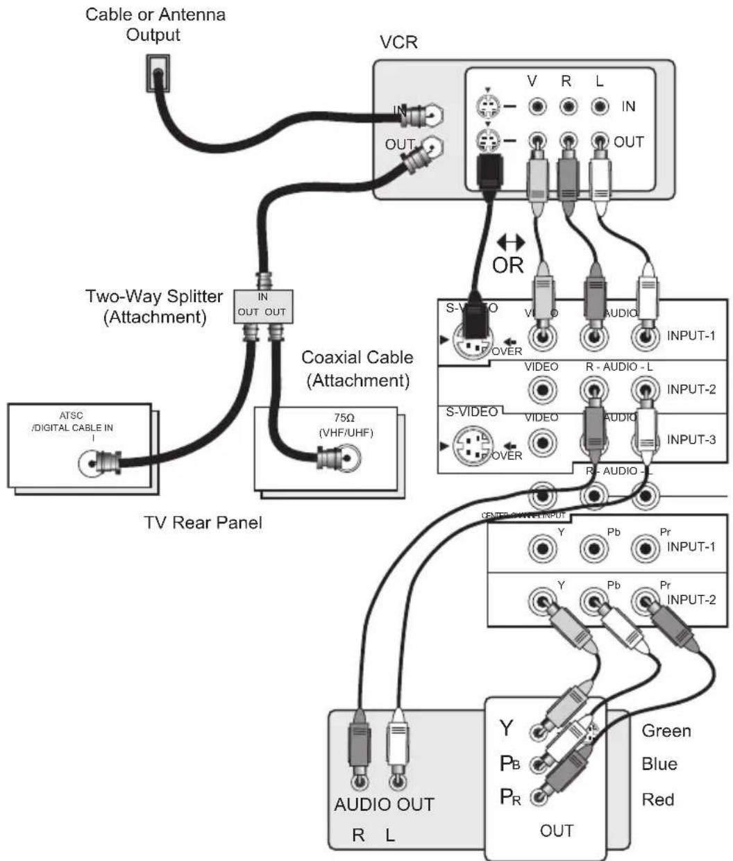
VCR Connection
Notes:
- Green, blue and red are the most common colors for DVD cables. Some models may vary colors. Please consult the user's manual for your DVD player for more information.
- Be careful not to confuse the red DVD cable with the red audio cable. It is best to complete one set of connections (DVD or audio output) before starting the other to avoid accidentally switching the cables.
• You may also connect the DVD player to Input 1.
Diagram #1
flowchart
graph TD
    A["Cable or Antenna Output"] --> B["VCR"]
    B --> C["Two-Way Splitter (Attachment)"]
    C --> D["TV Rear Panel"]
    D --> E["ATSC/DIGITAL CABLE IN"]
    B --> F["Coaxial Cable (Attachment)"]
    F --> G["S-VIDEO"]
    G --> H["VIDEO"]
    H --> I["AUDIO"]
    I --> J["INPUT-1"]
    F --> K["VIDEO"]
    K --> L["VIDEO"]
    L --> M["AUDIO"]
    M --> N["INPUT-2"]
    F --> O["VIDEO"]
    O --> P["VIDEO"]
    P --> Q["AUDIO"]
    Q --> R["INPUT-3"]
    F --> S["VIDEO"]
    S --> T["VIDEO"]
    T --> U["AUDIO"]
    U --> V["INPUT-4"]
    F --> W["VIDEO"]
    W --> X["VIDEO"]
    X --> Y["AUDIO"]
    Y --> Z["INPUT-5"]
    F --> AA["VIDEO"]
    AA --> AB["VIDEO"]
    AB --> AC["AUDIO"]
    AC --> AD["INPUT-6"]
    F --> AE["VIDEO"]
    AE --> AF["VIDEO"]
    AF --> AG["AUDIO"]
    AG --> AH["INPUT-7"]
    F --> AI["VIDEO"]
    AI --> AJ["VIDEO"]
    AJ --> AK["AUDIO"]
    AK --> AL["INPUT-8"]
    F --> AM["VIDEO"]
    AM --> AN["VIDEO"]
    AN --> AO["AUDIO"]
    AO --> AP["INPUT-9"]
    F --> AQ["VIDEO"]
    AQ --> AR["VIDEO"]
    AR --> AS["AUDIO"]
    AS --> AT["INPUT-10"]
DVD Player (OPTIONAL)
Note:
- If this connection setup does not work for you, try the connection setup on page 18.
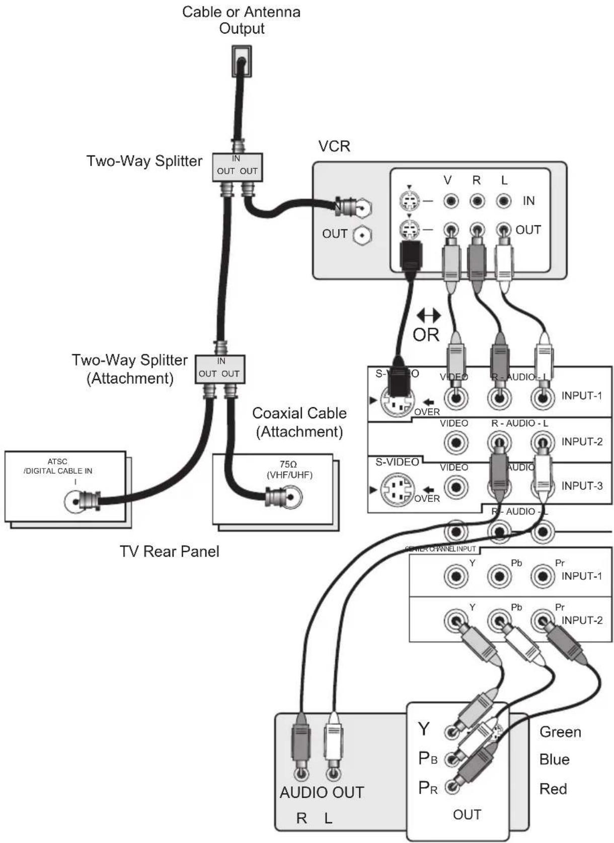
Quick Setup
Connections
Diagram #2
flowchart
graph TD
    A["Cable or Antenna Output"] --> B["Two-Way Splitter"]
    B --> C["VCR"]
    C --> D["Coaxial Cable (Attachment)"]
    D --> E["TV Rear Panel"]
    E --> F["AUDIO OUT R L"]
    F --> G["Green Blue Red"]
    F --> H["Output"]
    style A fill:#f9f,stroke:#333
    style B fill:#ccf,stroke:#333
    style C fill:#cfc,stroke:#333
    style D fill:#fcc,stroke:#333
    style E fill:#cff,stroke:#333
    style F fill:#ffc,stroke:#333
    style G fill:#cfc,stroke:#333
    style H fill:#fcc,stroke:#333
DVD Player (OPTIONAL)
Connecting to Monitor/Recording Output Terminal
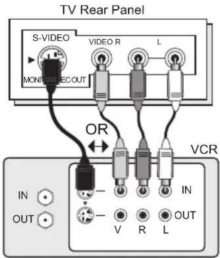
text_image
TV Rear Panel S-VIDEO VIDEO R L MONTE REC OUT OR VCR IN OUT - - V R L IN OUTNotes:
- When you make this connection, set the Video-1 Monitor Out menu to ON. See page 57.
- If you are receiving ATSC/Digital Cable signal, it can be outputted to the S-Video output terminal or Video (composite video) terminal.
- If you are receiving Analog TV signal, it can not be outputted to the S-Video output terminal.
- No signal will be outputted through the S-Video output terminal when you are not viewing images coming from the composite video input terminal.
- No signal will be outputted through the Monitor/Recording output terminal when you are viewing images from the component video input.
- If you try and record copyright protected programs using a VCR, you will not be able to record correctly. This is because of the copyright protection system. If you are watching a copyright protected program using a VCR, the picture will be distorted on the TV. This is due to the copyright protection system, and is not a malfunction of your TV.
Connecting to JVC AV Compu Link
JVC's AV CompuLink feature makes playing video tapes or DVDs totally automatic. Simply insert a pre-recorded tape into your JVC brand VCR or DVD into your JVC DVD player and the device will automatically turn on and begin playback. At the same time, using the AV CompuLink, the VCR or DVD player sends a signal to the television telling it to turn on and switch to the proper video input.
- The AV CompuLink cable may be included with the JVC AV CompuLink unit you wish to connect. If it is not, contact JVC Parts Department at (800)-882-2345, or www.jvcservice.com for part # EWP 805-012.
• AV CompuLink can only be used with JVC brand products.
AV CompuLink Cable

natural_image
Silhouette of a black electrical plug with a terminal and coiled cable (no text or symbols)To Connect: Plug one end of the AV CompuLink cable into the AV COMPULINK INPUT on your VCR, DVD, or other CompuLink device. Plug the other end of the AV CompuLink cable into the AV COMPULINK at the rear of the television.
Note:
- The AV CompuLink cable has a male 3.5 mm (mono) plug on each end.
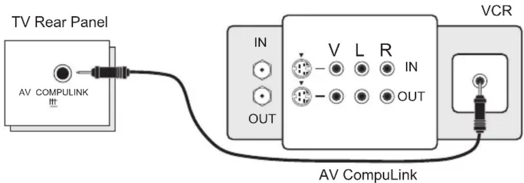
text_image
TV Rear Panel AV COMPULINK IN OUT V L R IN OUT VCR AV CompuLinkNotes:
- In order for the VCR playback to begin automatically, the recording tabs must be removed from the VHS tape. If the tab is in place, automatic switching will occur when you push the VCR's PLAY button.
- If your JVC brand VCR has "A code/B code remote control switching" (see your VCR's instruction book), using VCR A code will switch the TV to input 1.
• Refer to your DVD instruction book for detailed connection information. - To connect a JVC HiFi receiver or amplifier for a completely automated home theater, see the receiver connection instructions for detailed connection information.
- AV CompuLink is compatible with select AV CompuLink receivers.
Quick Setup
Connections
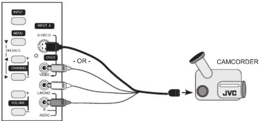
Connecting to a Camcorder
You may connect a camcorder, game console or other equipment to your television by using the side input jacks (Input 4) located on the side of the television. You can also connect these using the television's rear input jacks, using the same instructions.
flowchart
graph TD
    A["INPUT"] --> B["INPUT 4"]
    C["MENU"] --> B
    D["OPERATE"] --> B
    E["CHANNEL"] --> B
    F["VOLUME"] --> B
    B --> G["S-VIDEO"]
    B --> H["OVER"]
    B --> I["VIDEO"]
    B --> J["L/MONO"]
    B --> K["R"]
    B --> L["AUDIO"]
    G --> M["- OR -"]
    H --> M
    I --> M
    J --> M
    K --> M
    L --> M
    M --> N["CAMCORDER"]
    N --> O["JVC"]
1) Connect a yellow composite cable from the camcorder VIDEO OUT, into the VIDEO IN on the side of the TV, OR connect an S-Video cable from the side of the TV to the camcorder.
2) Connect a white cable from the camcorder LEFT AUDIO OUT, into the LEFT AUDIO IN on the side of the TV.
3) Connect a red cable from the camcorder RIGHT AUDIO OUT, into the RIGHT AUDIO IN on the side of the TV.
Note:
- If your camcorder is a mono sound model it will have only one AUDIO OUT. Connect it to the L/MONO on the side of the TV.
Quick Setup
Connections
Connecting to the Surround Amplifier
In multi-channel sound such as 5.1 channel, the speech characters are played back from the center speaker.
A center speaker in a movie theater is set in back of the screen so it can recreate a conversation scene in the movie more naturally. By using your TV's speaker as the center speaker, you can obtain the same sound effect as in a movie theater in you home theater sound system.
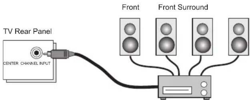
text_image
TV Rear Panel CENTER CHANNEL INPUT Front Front SurroundCENTER CHANNEL OUTPUT (VARIABLE OUTPUT)
1) Connect the Pin cable from the TV's CENTER CHANNEL INPUT terminal to the surround amplifier's CENTER CHANNEL OUTPUT terminal.
Note:
- Please read the benefit of this feature on page 59.
Connecting to an External Amplifier
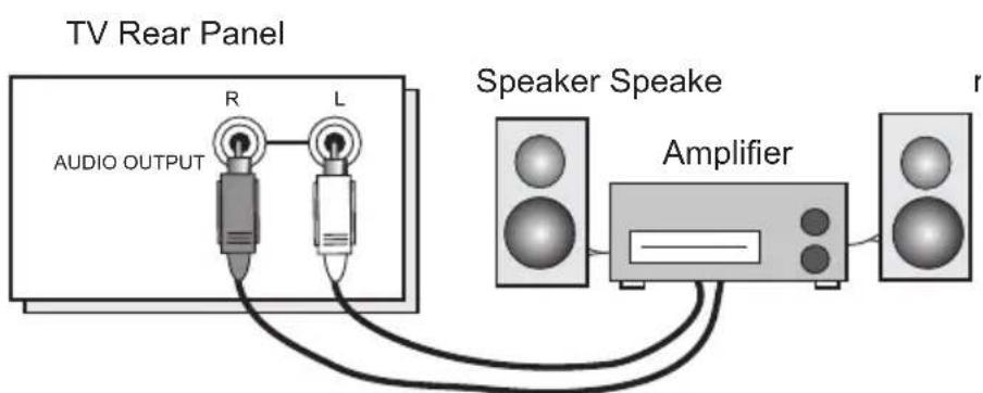
text_image
TV Rear Panel AUDIO OUTPUT R L Speaker Speake Amplifier1) Connect a white cable from the LEFT AUDIO OUTPUT on the back of the TV to the LEFT AUDIO INPUT on the amplifier.
2) Connect a red cable from the RIGHT AUDIO OUTPUT on the back of the TV to the RIGHT AUDIO INPUT on the amplifier.
Notes:
• Refer to your amplifier's manual for more information.
• You can use AUDIO OUTPUT for your home theater system.
- You can not output audio using the AUDIO OUTPUT under the following conditions:
1) When you have digital sound from an HDMI device connected to the HDMI 1 or HDMI 2 connection on the back of your TV. (See page 25).
2) When you have analog sound from a DVI device connected to the AUDIO IN "HDMI 1" connection. (See page 24).
Connecting to an amplifier using your optical output
You can connect an amplifier that has an optical digital input terminal by using an optical digital cable from the optical output. The signal that is output can be PCM or Dolby Digital.
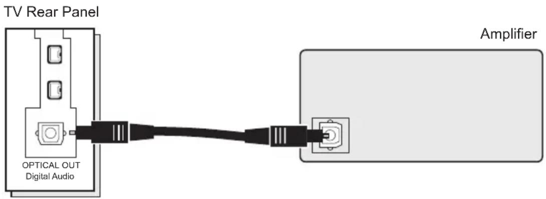
text_image
TV Rear Panel OPTICAL OUT Digital Audio Amplifier1) Connect the optical cable from the back of the TV to the back of the amplifier.
Notes:
• This terminal can only output digital audio.
- In order to use the optical output connection, select PCM or Dolby Digital on Digital Sound in the Digital Setup Menu. See page 79.
• Refer to your owners manual on using your amplifier.
Connecting to a Digital TV Receiver
By connecting a Digital TV Receiver, high definition pictures can be displayed on your TV in their digital form.
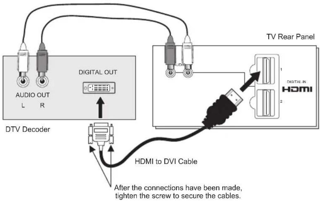
text_image
DTV Decoder AUDIO OUT L R DIGITAL OUT Audi Audi TV Rear Panel DIGITAL IN HDMI 2 HDMI to DVI Cable After the connections have been made, tighten the screw to secure the cables.1) Connect the HDMI to DVI Cable from the DIGITAL OUT on the back of your DTV decoder, to the DIGITAL-IN on the back of your television.
2) Connect a red cable from the "R AUDIO OUT" on the back of your DTV Device, to the HDMI "R AUDIO" input terminal.
3) Connect a white cable from the "L AUDIO OUT" on the back of your DTV Device, to the HDMI "L AUDIO" input terminal.
- The digital-in terminal is not compatible with the picture signal of a personal computer.
- Use a HDMI to DVI cable (commercially available) in order to digitally connect the television with a DTV decoder.
Notes:
- If 480p signals (640x480 or 720x480) are displayed on the screen, the horizontal balance may be slightly shifted. Access the "DIGITAL-IN" in the initial setup menu to adjust it. (Refer to page 58.)
- When you do the above connection, set DIGITAL-IN AUDIO in the Initial Setup menu to ANALOG. See "DIGITAL-IN AUDIO", page 58.
- The Analog Audio input can only be used with the HDMI 1 input.
- When setting the "DIGITAL AUDIO – ANALOG / DIGITAL" menu setting on the TV, please note that this setting only effects the HDMI 1 jack and that if you use a DVI to HDMI adapter this connection must be made to the HDMI 1 along with analog audio cables.
Connecting to an HDMI Compatible Device
By connecting an HDMI compatible device, high definition pictures can be displayed on your TV in their digital form. Some HDMI devices can include DVD players, D-VHS or any HDMI compatible devices.
HDMI (High Definition Multimedia Interface) is the first industry supported, uncompressed, all digital audio/video interface. HDMI provides and interface between any audio/video source, such as a set-top box, DVD player, A/V receiver or an audio and/or video monitor, such as a digital television (DTV).
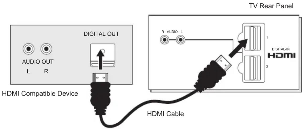
text_image
TV Rear Panel AUDIO OUT L R DIGITAL OUT HDMI Compatible Device R - AUDIO - L DIGITAL-IN HDMI 2 HDMI Cable1) Connect the HDMI Cable from the DIGITAL OUT on the back of your DTV or HDMI device, to the DIGITAL-IN on the back of your television.
Notes:
- When you do the above connection, set DIGITAL-IN AUDIO in the Initial Setup menu to DIGITAL. See "DIGITAL-IN AUDIO", page 58.
- Some decoders may not respond depending on the equipment that you have connected when it is connected to the HDMI.
- If the HDMI output device signal is changed (for example, 480i/60Hz is changed to 480p/60Hz), the screen may turn green and there may be some distortion for a short time until the signal becomes stable.
- When you have an HDMI device connected to the HDMI 1 connection on the back of your TV, your TV detects it, and blocks the analog audio signal coming into the "HDMI 1" jacks. Therefore, you can not hear any analog sound from the other device connected to the "HDMI 1" jacks, while you are viewing the images from the HDMI device.
Connecting to an AV Receiver using your television's V1 Smart Input
By connecting your AV Receiver to your television's V1 Smart Input, you can watch picture sources from many different devices, without having to change or use the other input connections on your TV. This allows you to free up the other input connections so you can connect more devices to your television.
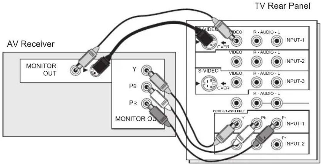
text_image
TV Rear Panel AV Receiver MONITOR OUT Y Pb Pr MONITOR OUT S-VIDEO VIDEO R - AUDIO - L INPUT-1 OVER VIDEO R - AUDIO - L INPUT-2 S-VIDEO VIDEO R - AUDIO - L INPUT-3 OVER R - AUDIO - L CENTER OAMIN INPUT Y Pb Pr INPUT-1 Pr INPUT-21) Connect an S-Video Cable from the AV Receiver's MONITOR OUT, to the S-Video INPUT-1 on the back of your television.
2) Connect a Yellow Composite Cable from the AV Receiver's MONITOR OUT, into the VIDEO INPUT-1 on the back of your television.
3) Connect a Green Component Cable from the AV Receiver's Y MONITOR OUT, into the Y VIDEO INPUT-1 on the back of your television.
4) Connect a Blue Component Cable from the AV Receiver's R MONITOR OUT, into the Pb VIDEO INPUT-1 on the back of your television.
5) Connect a Red Component Cable from the AV Receiver's PR MONITOR OUT, into the Pr VIDEO INPUT-1 on the back of your television.
Note:
- Please refer to your AV Receiver instruction manual for more information on connecting your speakers and other devices like a DVD player.
- Use your AV Receiver's remote to switch to the different devices you have connected.
- Some AV Receivers may not respond when the V1 Smart Input function is turned on.
- If you have video connections for each input device connected to your AV Receiver, you should not connect them using both S-Video and Composite connection at the same time when you are using V1 Input as the V1 Smart Input. In this case we recommend using the S-Video connection.
Connecting an i.LINK compatible device to the back of your television
i.LINK is a digital serial interface that allows devices equipped with an i.LINK connector to exchange digital video signals, digital audio signals and device control signals bi-directionally over a single cable. (For example, a JVC D-VHS VCR).
i.LINK refers to the IEEE1394-1995 industry specification and extensions thereof. The i logo is used for products compliant with the i.LINK standard.
This projection television uses a four-pin i.LINK connector to input and output MPEG2 video signals, audio signals and control signals.
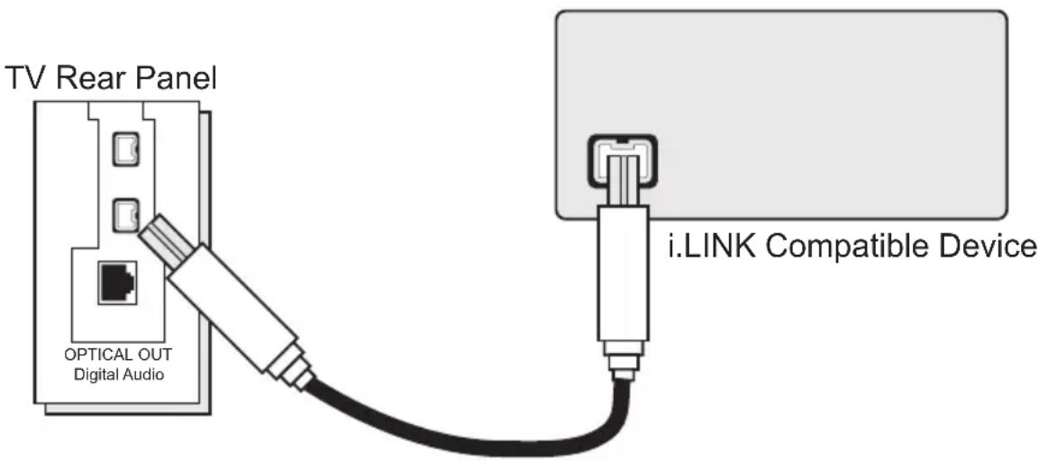
text_image
TV Rear Panel OPTICAL OUT Digital Audio i.LINK Compatible Device1) Connect the i.LINK cable from the back of the TV to the back of the i.LINK compatible device.
Notes:
- Use only the S400 i.LINK cable when connection your devices.
• See page 83 on how to select the i.LINK device.
• Refer to your owners manual on using your i.LINK device. - When recording or playing back video with an i.LINK device, if you perform the Auto Tuner Setup, the video signal you are recording or playing back may stop or you may not be able to perform the Digital Auto Tuner Setup.
- Your television can connect with i.LINK D-VHS decks and HD-Camcorders (JVC brand only). If you connect other brand devices, with i.LINK cable, they will not work.
- It can play only the recorded contents in Digital Mode.
- Use only tapes bearing the DVHS (SVHS) mark for recording.
Connecting to the computer
This TV can be used as a computer screen. Use a commercially available D-SUB cable to connect the TV's PC INPUT terminal to the computer's analog RGB output terminal. If you want to listen to the sound from the computer, use a commercially available RCA cable to connect the INPUT-3 audio input terminal to the computer's audio output terminal.
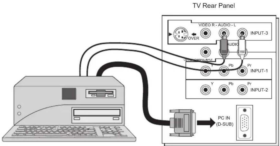
text_image
TV Rear Panel VIDEO R - AUDIO - L OVER AUDIO INPUT-3 GENERAL CHANNEL INPUT Y Pb Pr INPUT-1 Y Pb Pr INPUT-2 PC IN (D-SUB)Notes:
• Refer to your computer manual for a detailed explanation of the connections concerning your computer.
• Make sure that the connectors are facing the correct way when connecting.
• After connecting, tighten the two screws to fix the connectors in place.
Looking at the images from a computer
After starting the computer, press the INPUT button to choose INPUT-3. You can listen to the sound when the sound from the computer is connected to the INPUT-3 AUDIO input terminal.
Notes:
- When the sound from the computer is connected to INPUT-3 by choosing external input INPUT-3, the sound from the computer can be listened to, but the images from the computer cannot be seen.
Table of signals for each type of computer
| Resolution | Vertical Frequency (Hz) | Horizontal Frequency (kHz) |
| 640 x 480 (VGA) | 60.0 | 31.5 |
| 1024 x 768 (XGA) | 60.0 | 48.4 |
- Only the above formats are supported.
- Even with the above formats at 60 Hz, some problems may be experienced depending on the quality of the synchronous signal. (Depending on the quality, some pictures may not be displayed correctly).
- Apple Macintosh* computers are not supported.
When a picture is not displayed
With some computers, some problems can be solved by changing the settings. Check the computer's refresh rate and set it to 60Hz. Computers that cannot set the refresh rate to 60 Hz, can not be used with this TV. Refer to the computer's instruction manual.
*Apple Macintosh is a registered trademark of Apple Computer, Inc.
Note:
- If you are inputting a PC signal that is invalid, "Invalid Signal" will appear on the TV screen. It appears when the input is PC and it is a single screen.
Step 3 – The Interactive Plug In Menu
When you turn your television on for the first time the interactive plug-in menu will appear. The plug-in menu helps you to get your TV ready to use by letting you set your preferences for:
- The language in which you want the onscreen menus to appear.
- Setting the TV's clock to the correct time so your timer functions will work properly. You can choose "AUTO" or "MANUAL" for setting the clock.
- The auto tuner setup of which channels you wish to receive.
We recommend you complete the interactive plug-in items before you start using your television.
Notes:
- The interactive plug-in menu setting does not appear if your TV has been turned on before. In this case use the onscreen menus to perform these settings. See pages 50, 63, 40.
- If you press the Menu button while setting up the interactive plug-in menu, it will skip over it.
Language
After the “JVC INTERACTIVE PLUG IN MENU” has been displayed, the TV automatically switches to the LANGUAGE settings. You can choose to view your onscreen menus in three languages: English, French (Français) or Spanish (Español).
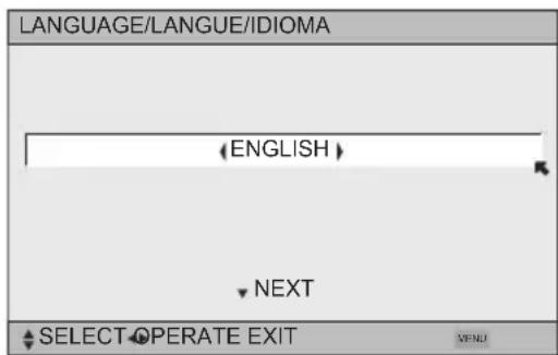
text_image
LANGUAGE/LANGUE/IDIOMA (ENGLISH) NEXT SELECT OPERATE EXIT VENU◀▶ To choose a language: (English, Français or Español)
▼ To NEXT (To set clock)
(To be continued...)
Auto Clock Set
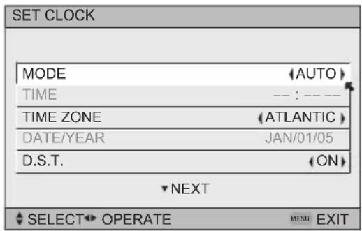
Before you use any of your TV's timer functions, you must first set the clock. You may precisely set your clock using the XDS time signal broadcast by most public analog broadcasting stations. If you do not have this in your area, you will have to set the clock manually. See manual clock set below. To set the clock using the XDS signal:
text_image
SET CLOCK MODE (AUTO) TIME --- : --- TIME ZONE (ATLANTIC) DATE/YEAR JAN/01/05 D.S.T. (ON) NEXT SELECT OPERATE MENU EXIT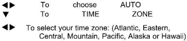
text_image
◀▶ To choose AUTO ▼ To TIME ZONE ◀▶ To select your time zone: (Atlantic, Eastern, Central, Mountain, Pacific, Alaska or Hawaii)▼ To move to D.S.T. (Daylight Savings Time)
◀▶ To turn D.S.T. ON or OFF
▼ To NEXT (To Auto Tuner Setup)
Notes:
• D.S.T. can be used when it is set to ON in the SET CLOCK menu.
- Only when the MODE is set to AUTO, the Daylight Savings Time feature automatically adjusts your TV's clock for Daylight Savings. The clock will move forward one hour at 2:00 am on the first Sunday in April. The clock will move back one hour at 2:00 am on the last Sunday in October.
- You will have to reset the clock after a power interruption. You must set the clock before operating any timer functions.
Manual Clock Set
To set your clock manually (without using the XDS signal), choose MANUAL. If you choose AUTO, see auto clock set above.
text_image
SET CLOCK MODE (MANUAL) TIME -- : -- TIME ZONE (ATLANTIC) DATE/YEAR JAN/01/05 D.S.T. (ON) ▼ START CLOCK ▼ SELECT OPERATE MEND EXIT ◀ To choose MANUAL ▼ To TIME ◀ To set the hour ▼ To minute ◀ To set the minute ▼ To TIME ZONE ◀ To select your time zone: (Atlantic, Eastern, Central, Mountain, Pacific, Alaska or Hawaii) ▼ To DATE/YEAR ◀ To set the month ▼ To day ◀ To set the day ▼ To year ◀ To set the year ▼ To move to D.S.T. (Daylight Savings Time) ◀ To turn D.S.T. ON or OFF ▼ To START CLOCKNote:
- You will have to reset the clock after a power interruption. You must set the clock before operating any timer functions.
(To be continued...)
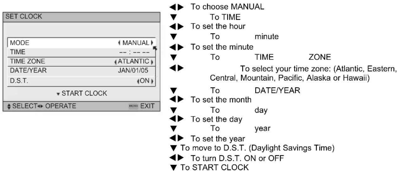
Auto Tuner Setup
In auto tuner setup, the TV automatically scans through all available channels, memorizing the active ones and skipping over blank ones or channels with weak signals. This means when you scan (using the CHANNEL +/- buttons) you will receive only clear, active channels. There are two tuner modes to choose from, ANALOG or DIGITAL.
text_image
AUTO TUNER SETUP IN ANALOG AIRTUNER MODE IN DIGITAL TUNER MODE ATSC START SELECT OPERATE EXIT MENU After Tunes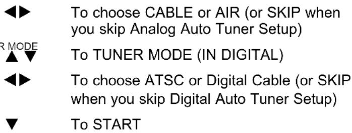
text_image
◀▶ To choose CABLE or AIR (or SKIP when you skip Analog Auto Tuner Setup) R MODE ▲▼ To TUNER MODE (IN DIGITAL) ◀▶ To choose ATSC or Digital Cable (or SKIP when you skip Digital Auto Tuner Setup) ▼ To STARTAfter Analog Auto Tuner Setup is finished, Digital Auto Tuner Setup starts.
text_image
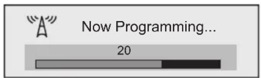
Now Programming... 20

text_image
NOW PROGRAMMING ! >>> □ >>> 48When the setup is finished, "THANK YOU ! SETUP IS NOW COMPLETE" is displayed. Your quick setup is now complete. You can now begin watching your television, or you can continue on in this guide for more information on programming your remote control, or using the JVC onscreen menu system to customize your television viewing experience.
Notes:
- If you want to cancel the Auto Tuner Setup, press the MENU button.
- Noise muting will not work during Auto Tuner Setup.
- If you choose SKIP, it finished without doing the Auto Tuner Setup.
Cable Box and Satellite Users: After your auto tuner setup is complete, you may, (depending on the type of hookup), have only 1 channel, usually 3 or 4 in the auto tuner memory. This is normal.

text_image
STOPThe Quick Setup is complete
Remote Programming
Setting the CATV, VCR and DVD Codes
You can program your remote to operate your cable box, satellite receiver, VCR or DVD player by using the instructions and codes listed below. If the equipment does not respond to any of the codes listed below or to the code search function, use the remote control supplied by the manufacturer.
Cable Box or Satellite Codes
The remote control is programmed with cable box and satellite codes for power on/off, channel up/down, and 10 key operation.
1) Find the cable box or satellite brand from the list of codes shown below.
2) Slide the 2-way selector switch to "CATV".
3) Press and hold down the DISPLAY button, then enter the first code number listed with the 10 key pad.
4) Release the DISPLAY button, and confirm the operation of the cable box/satellite receiver.
- If your cable or satellite box does not respond to the first code, try the others listed. If it does not respond to any code, try the search codes function, on page 36.
| Cable Box Codes | Cable Box Codes | Digital Satellite Systems | Codes | ||
| ABC | 024 | Puser | 032 | ||
| Archer | 032, 025 | RCA | 061, 070 | Echostar (Dish Network) | 100, 113, 114, 115 |
| Cableview | 051, 032 | Realistic | 032 | ||
| Citizen | 022, 051 | Regal | 058, 064, 040, 041, 042, 045, 068 | Express VU | 100, 113 |
| Curtis | 058, 059 | G.E. | 106 | ||
| Diamond | 024, 032, 025 | Regency | 034 | G.I. | 108, 120, 121, 122 |
| Eagle | 029 | Rembrandt | 037, 032, 051, 038 | ||
| Eastern | 034 | ||||
| GC Brand | 032, 051 | Samsung | 051 | Gradiente | 112 |
| Gemini | 022, 043 | Scientific Atlanta | 057, 058, 059 | Hitachi | 104, 111 |
| General Instrument/Jerrold | 065, 024, 025, 026, 027, 020, 021, 022, 057, 023, 072, 074 | SLMark | 051, 047 | HNS (Hughes) | 104 |
| Sprucer | 051, 056 | Magnavox 102, | 103 | ||
| Stargate | 032, 051 | Panasonic | 105 | ||
| Hamlin | 040, 041, 042, 045, 058, 064 | Telecaption | 067 | Philips | 102, 103, 116 |
| Hitachi | 049, 024 | Teleview | 047, 051 | Primestar | 108 |
| Macom | 049, 050, 051, 054 | Texscan | 044 | Proscan | 106, 109, 110 |
| Tocom | 035, 036, 066, 074 | RCA | 106, 109, 110 | ||
| Magnavox | 033 | Sony | 107 | ||
| Memorex | 030 | Toshiba | 050, 048 | Star Choice | 104, 108 |
| Movietime | 032, 051 | Unika | 032, 025 | Toshiba | 101, 104, 117, 118, 119 |
| Oak | 039, 037, 048 | Universal | 022, 032 | ||
| Panasonic | 055, 056, 060, 071, 073 | Videoway | 052 | Uniden | 102, 103 |
| Paragon | 063 | Viewstar | 029, 030 | ||
| Philips | 028, 029, 030, 052, 053, 031, 069 | Zenith | 063, 046 | ||
| Zenith/Drake Satellite | 046 | ||||
| Pioneer | 047, 062 | ||||
| Pulsar | 051, 032 |
Remote Programming
VCR Codes
The remote control is programmed with VCR codes for power on/off, play, stop, fast-forward, rewind, pause, record, channel up/down operation.
1) Find the VCR brand from the list of codes shown below.
2) Slide the first 2-way selector switch to "TV" and the other 2-way selector switch to "VCR".
3) Press and hold down the DISPLAY button, then enter the first code number listed with the 10 key pad.
4) Release the DISPLAY button, and confirm the operation of the VCR.
- If your VCR does not respond to the first code, try the others listed. If it does not respond to any of the codes, try the search codes function on page 36.
- After you program your remote, some VCR buttons may not work properly. If so, use the VCR's remote.
- To record, hold down the Rec button on the remote and press PLAY.
| VCR | Codes | VCR VCR | Codes | Codes | |
| Admiral | 035 | Marantz | 003, 004, 005 | Samsung | 037, 060, 062, 033, 089 |
| Aiwa | 027, 032, 095 | Marta | 064 | ||
| Akai | 029, 072, 073, 074 | Memorex | 024, 067 | Samtron | 089 |
| MGA | 038, 040, 047, 048, 041, 042 | Sansui | 003, 026, 020, 052 | ||
| Audio Dynamic | 003, 005 | ||||
| Bell & Howell | 063, 071 | Minolta | 058, 045, 093 | Sanyo | 063, 067, 091, 071 |
| Broksonic | 020, 026, 094 | Mitsubishi | 038, 040, 047, 048, 041, 042, 078, 090 | Scott | 059, 060, 062, 067, 038, 040, 047, 048, 026, 020 |
| Canon | 023, 025 | ||||
| CCE | 043 | Multitech | 047, 027, 062 | ||
| Citizen | 064 | NEC | 003, 004, 005, 000 | Sears | 063, 064, 065, 066, 058 |
| Craig | 063, 029, 064 | ||||
| Curtis Mathes | 045, 024, 027, 093 | Olympic | 024, 023 | Sharp | 035, 036, 080, 088 |
| Daewoo | 043, 059, 024, 092 | Optimus | 028, 021, 035, 064 | Shintom 075 | |
| DBX | 003, 004, 005 | Orion | 026, 020 | Signature 2000 | 027, 035 |
| Dimensia | 045, 093 | Panasonic | 023, 024, 021, 022 | Singer | 075 |
| Emerson | 043, 026, 077, 061, 025, 042, 020, 076 | Penney | 024, 058, 045, 063, 003, 004, 005, 093 | Sony | 028, 029, 030, 053, 054, 055 |
| Fisher | 063, 066, 067, 065, 071, 091 | Pentax | 058, 005, 045, 093 | SV 2000 | 027 |
| Sylvania | 031, 023, 024, 027 | ||||
| Funai | 027, 026, 020, 000 | Philco | 031, 024, 027, 023, 026, 020, 043 | Symphonic | 027, 081 |
| G.E. | 033, 045, 024 | Tashiro | 064 | ||
| Go Video | 037, 051, 049, 050, 089 | Philips | 031, 023, 024, 086 | Tatung | 003, 004, 005 |
| Teac | 003, 004, 027, 005 | ||||
| Goldstar | 064 | Pioneer | 023 | ||
| Gradiente | 083, 084, 081, 000, 001 | Proscan | 045, 058, 023, 024, 031, 046, 059, 060, 093, 033, 087 | Technics | 021, 022, 023, 024 |
| Hitachi | 023, 045, 058, 093, 027, 081 | Teknika | 024, 027, 070 | ||
| Quasar | 021, 022, 023, 024 | Thomson 033, 096 | |||
| Instant Replay | 024, 023 | Toshiba | 059, 046, 079 | ||
| Jensen | 003 | Radio Shack | 033, 024, 063, 036, 067, 040, 027 | Vector Research | 005 |
| JVC | 003, 004, 005, 000, 001, 002, 006, 007 | Wards | 035, 036, 067, 044, 064 | ||
| RCA | 033, 045, 058, 023, 024, 031, 046, 059, 060, 083, 084, 085, 087, 093, 096 | Yamaha | 063, 003, 004, 005 | ||
| Kenwood | 003, 004, 064, 005 | Zenith 044, 082 | 064, 094 | ||
| LG 064 | Realistic 024, 063, 036, 067, 040, 027 | ||||
| LXI 027, 064, 058, 065, 066, 063, 067 | |||||
| Magnavox | 031, 023, 024, 086 | ||||
Remote Programming
DVD Codes
The remote control is programmed with DVD codes for power on/off, play, stop, fast-forward, rewind, previous/next chapter, tray open/close, and still/pause operation.
1) Find the DVD player brand from the list of codes shown below.
2) Slide the first 2-way selector switch to "TV" and the other 2-way selector switch to "DVD".
3) Press and hold down the DISPLAY button, then enter the first code number listed with the 10 key pad.
4) Release the DISPLAY button, and confirm the operation of the DVD player.
- If your DVD player does not respond to the first code, try the others listed. If it does not respond to any of the codes, try the search codes function on page 36.
- After you program your remote, some DVD buttons may not work properly. If so, use the DVD player's remote.
| DVD Player | DVD Player | CodesDVD Player Codes Cod | |||
| Aiwa 043 | Mintek 057 | Sharp | 028 | ||
| Apex 040, 054, 055 | Mitsubishi 025 | Silvania | 038 | ||
| Bose 058 | Next Base | 056 | SMC | 048 | |
| Denon 020, 037 | Onkyo 041, 052 | Sony 024, 045, 046, 047 | |||
| Funai | 038 | Oritron 044 | Technics | 020 | |
| Go–Video 032 | Panasonic | 020 | Thomson 021 | ||
| Harman Kardon | 053 | Philips 023, 036 | Toshiba | 023 | |
| Hitachi 031 | Pioneer | 022 | Venturer | 051 | |
| JVC 000 | Polk Audio | 036 | Vialta | 050 | |
| Kenwood 035, 020 | Raite | 033 | Wave | 042 | |
| KLH | 051 | RCA | 021, 026 | Yamaha | 020, 049 |
| Konka 039 | Sampo | 034 | Zenith | 027, 032 | |
| Koss | 050 | Samsung | 030 |
Remote Programming
Search Codes
Cable/Satellite Search Codes Function
1) Slide the first 2-Way Mode Selector switch to CATV.
2) Press the POWER and RETURN+/TV buttons. Hold for at least three seconds and release.
3) Press the POWER button on the remote, and see if the cable or satellite box responds.
4) If there was a response, press RETURN+/TV. The codes are now set. If there was no response, repeat Step 3. If you repeat Step 3 a total of 80 times without a response, use the remote control that came with your equipment.
5) Press RETURN+/TV to exit.
VCR/DVD Search Codes Function
1) Slide the first 2-way selector switch to "TV" and the other 2-way selector switch to "VCR" or "DVD".
2) Press the VCR or DVD POWER and RETURN+/TV buttons. Hold for at least three seconds and release.
3) Press the VCR or DVD POWER button, and see if the VCR or DVD responds.
4) If there was a response, press RETURN+/TV. The codes are now set. If there was no response, repeat Step 3. If you repeat Step 3 a total of 80 times for the VCR (40 times for the DVD player), and there is no response, use the remote control that came with your equipment.
5) Press RETURN+/TV to exit.
Onscreen Menus
Using the Guide
Certain symbols are used throughout this guide to help you learn about the features of your new television. The ones you will see most frequently are:
▲ ▼ Up and Down arrows mean press the CH+ or CH- buttons. Pressing the CH+ or CH- buttons let you:
- Move vertically in a main menu screen
- Move through a submenu screen
- Move to the next letter, number, or other choice in a submenu
- Back up to correct an error
- Scan through TV channels (when not in a menu screen)
Left and right arrows mean press the VOLUME+ or VOLUME- buttons to move left or right to:
- Select a highlighted menu item
- Select an item in a submenu
- Select numbers in certain menu options
- Turn the volume up or down (when not in a menu screen)

The "press button" icon means you should press the button named on your remote control. (Button names appear in SMALL CAPITAL LETTERS.)
The "helping arrow" icon points to the highlighted or selected item in a menu.
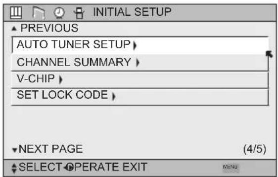
To bring up the onscreen menu, press the MENU button on the remote control. The item that appears in green is the one currently selected. If you use the Menu button on the TV's side panel instead of the remote, an additional menu screen showing VIDEO STATUS and ASPECT will appear between INITIAL SETUP and PICTURE ADJUST. The "interactive plug-in menu" will appear the first time the TV is plugged in.
text_image
INITIAL SETUP ▲ PREVIOUS AUTO TUNER SETUP > CHANNEL SUMMARY > V-CHIP > SET LOCK CODE > NEXT PAGE (4/5) SELECT OPERATE EXIT MENUNote:
- Menus shown in this book are illustrations, not exact replications of the television's onscreen displays.
Onscreen Menus
The Onscreen Menu System
Your television comes with JVC's onscreen menu system. The onscreen menus let you make adjustments to your television's operation simply and quickly. Examples of the onscreen menus are shown on the next page. Detailed explanations on using each menu follow later in this guide. For information about the interactive plug-in Menu, see pages 30 - 32.
The Onscreen Menu System
To open the onscreen menu system, press the MENU button on the remote control. You navigate within the onscreen menus by using the four directional arrow buttons on the remote control. (These buttons are also the CH +/- and VOL +/- buttons. Channel and volume functions will not operate when the onscreen menu is active).
The selected feature and option on a menu screen are highlighted in a different color.
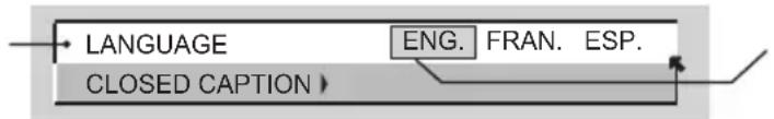
Selected Option (Green)
text_image
LANGUAGE CLOSED CAPTION ENG. FRAN. ESP.Selected Option (Blue)
To move to a different feature use the ▲▼ arrows to move up or down the list. When you press the up arrow at the top of the list or the down arrow at the bottom, the next menu screen will appear. Use the arrows ◀▶ to select an option from the highlighted feature. Pressing MENU on the remote control will close the onscreen menu system and return you to normal television viewing.
Each menu and its features will be discussed in the following pages of this guide.
Notes:
- If you do not press any buttons for about a minute, the onscreen menu will automatically shut off.
- Button names in this guide are shown in SMALL CAPITAL LETTERS.
- Menus may appear in different sizes onscreen depending on the aspect ratio selected.
- Some menu items may not appear in menu screens when certain aspect ratios or inputs are selected.
Onscreen Menus
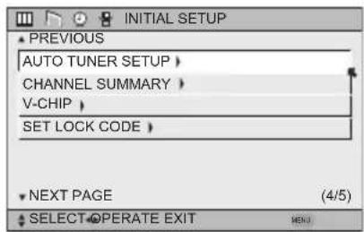
Press the MENU button
text_image
PREVIOUS AUTO TUNER SETUP > CHANNEL SUMMARY > V-CHIP > SET LOCK CODE > NEXT PAGE (4/5) SELECT OPERATE EXIT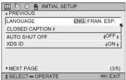
text_image
PREVIOUS LANGUAGE ENG. FRAN. ESP. CLOSED CAPTION > AUTO SHUT OFF (OFF) XDS ID (ON) NEXT PAGE (3/5) SELECT OPERATE HOME EXIT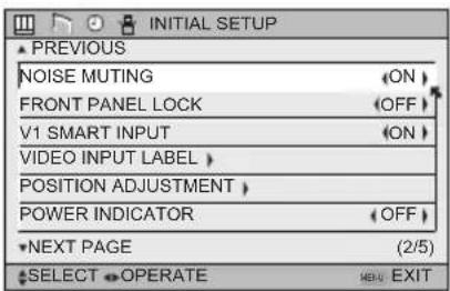
text_image
INITIAL SETUP PREVIOUS NOISE MUTING FRONT PANEL LOCK V1 SMART INPUT VIDEO INPUT LABEL POSITION ADJUSTMENT POWER INDICATOR NEXT PAGE (2/5) SELECT OPERATE EXIT EXITINITIAL SETUP 03 INITIAL SETUP 02
INITIAL SETUP 04
text_image
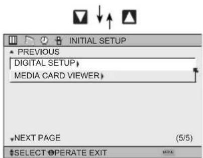
INITIAL SETUP PREVIOUS DIGITAL SETUP MEDIA CARD VIEWER NEXT PAGE (5/5) SELECT OPERATE EXITINITIAL SETUP 05
text_image
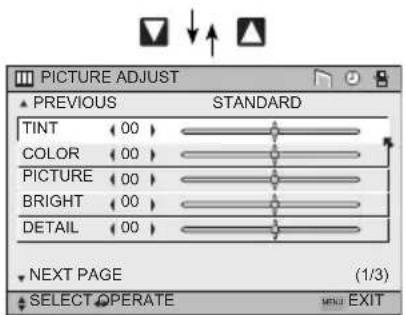
PICTURE ADJUST ▲ PREVIOUS STANDARD TINT (00) COLOR (00) PICTURE (00) BRIGHT (00) DETAIL (00) NEXT PAGE (1/3) SELECT OPERATE MENU EXITPICTURE ADJUST 01
text_image
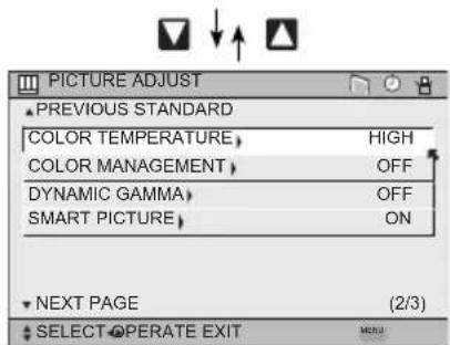
PICTURE ADJUST PREVIOUS STANDARD COLOR TEMPERATURE, HIGH COLOR MANAGEMENT, OFF DYNAMIC GAMMA, OFF SMART PICTURE, ON NEXT PAGE (2/3) SELECT OPERATE EXITPICTURE ADJUST 02
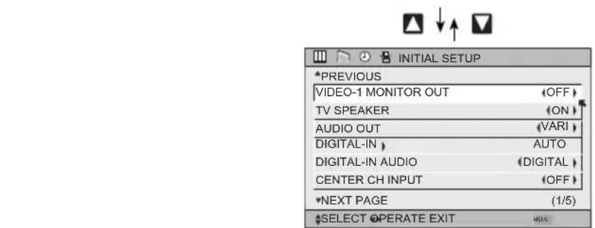
text_image
INITIAL SETUP *PREVIOUS VIDEO-1 MONITOR OUT TV SPEAKER AUDIO OUT DIGITAL-IN DIGITAL-IN AUDIO CENTER CH INPUT *NEXT PAGE (1/5) *SELECT OPERATE EXITINITIAL SETUP 01
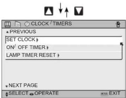
text_image
CLOCK / TIMERS PREVIOUS SET CLOCK > ON/ OFF TIMER > LAMP TIMER RESET > NEXT PAGE SELECT OPERATE EXITCLOCK/TIMERS
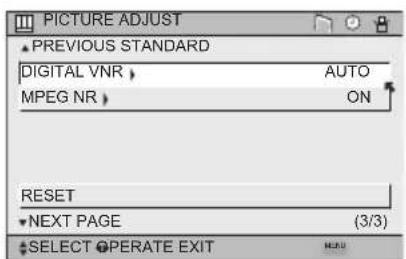
text_image
PICTURE ADJUST ▲ PREVIOUS STANDARD DIGITAL VNR > MPEG NR > AUTO ON RESET ▼ NEXT PAGE (3/3) ▲ SELECT OPERATE EXITPICTURE ADJUST 03
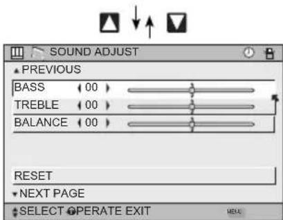
text_image
SOUND ADJUST ▲ PREVIOUS BASS 00 TREBLE 00 BALANCE 00 RESET ▼ NEXT PAGE ▲ SELECT OPERATE EXIT MENUSOUND ADJUST


Notes:
- The DIGITAL-IN menu can only be displayed when a 480p picture signal is input to the digital-in terminal and the picture is being displayed on the screen.
- SMART PICTURE menu cannot be displayed when DYNAMIC is selected for Video Status.
- When the Menu button on the TV side panel is pressed, the FRONT PANEL CONTROL menu between INITIAL SETUP 05 and PICTURE ADJUST 01 will appear.
- Regarding the digital setup menu, see page 78.
• MEDIA CARD VIEWER is for HD-P70R1U ONLY.
Initial Setup
Auto Tuner Setup
The auto tuner setup function is described on page 32 as the interactive plug-in menu. If you need to run the auto tuner setup again, follow the steps below.

ess the M
ENU button

To AUTO TUNER SETUP

To operate

To TUNER MODE (IN ANALOG)

To choose CABLE, AIR or SKIP

To TUNER MODE (IN DIGITAL)

To choose ATSC, DIGITAL CABLE or SKIP

Press the Ok button to start
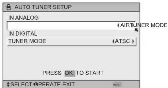
text_image
AUTO TUNER SETUP IN ANALOG (AIRTUNER MODE) IN DIGITAL TUNER MODE (ATSC) PRESS OK TO START SELECT OPERATE EXITProgramming will take approximately 2 to 4 minutes. The auto tuner is finished when the message PROGRAMMING OVER! appears onscreen.

Press the Menu button when finished
Note:
• Digital Auto Tuner Setup will take approximately 14 minutes.
Channel Summary
Channel summary allows you to customize the line-up of channels received by your TV. Regarding analog channels, you can add or delete channels from the line-up or prevent any unauthorized viewers from watching any or all 191 channels. Regarding digital channels, the only channels that will appear are the ones that are broadcasting.


Press
ENU thetton
M
To CHANNEL SUMMARY
To
operate
The Channel summary screen will now be displayed with the channels set to scan marked with an “√”. Regarding analog channels, you can delete channels from the scan by removing the “√”. If any channels were missed during auto tuner setup and you wish to add them, you may by placing an “√” next to the channel number.
- Digital channels can not be added to the channel summary if the auto tuner setup did not find them.

To the SCAN column

Press button to include or delete from
scan

Press
ENU thetton when finished
Note:
- The number of a digital channel may change, depending on the time of some broadcastings. If this channel existed and now had disappeared, the lock channel or scanned channel by the channel summary for that channel will be cancelled.
Analog Channels
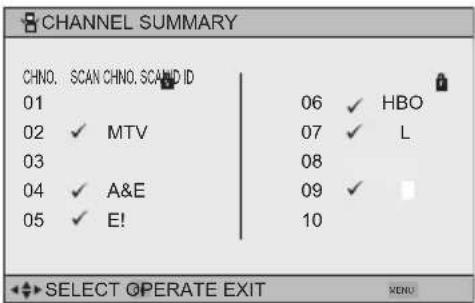
text_image
CHANNEL SUMMARY CHNO. SCAN CHNO. SCAND ID 01 06 ✓ HBO 02 ✓ MTV 07 ✓ L 03 08 04 ✓ A&E 09 ✓ 05 ✓ E! 10 SELECT OPERATE EXIT MENUDigital Channels
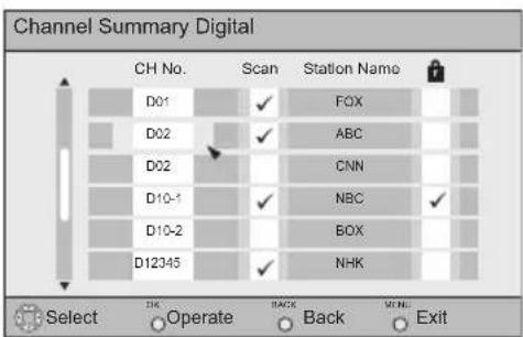
text_image
Channel Summary Digital CH No. Scan Station Name D01 ✓ FOX D02 ✓ ABC D02 CNN D10-1 ✓ NBC ✓ D10-2 BOX D12345 ✓ NHK Select OK Operate Back Menu ExitNote:
- When the Cable Card is not inserted into the Cable Card Slot:
If you are watching analog channels, the above screen appears.
If you are watching digital channels, the below screen appears.
- When the Cable Card is inserted into the Cable Card Slot:
Below screen appears Both analog and digital channels are listed, but the background video is not displayed.
Initial Setup
How to set the channel label. (This is only for analog broadcasting.)

ess the M
ENU button

To CHANNEL SUMMARY

To operate

To the ID column

ess the Ok button to enter

To select the character you want

To move to the next space
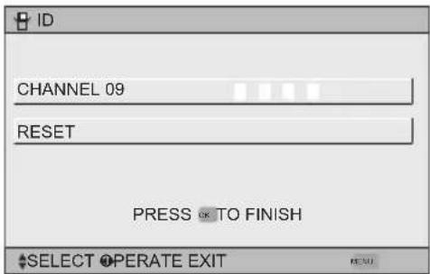
text_image
ID CHANNEL 09 RESET PRESS ⬆ TO FINISH SELECT OPERATE EXIT...continue to follow these directions for all four

ess the Ok button to finish
Your characters are now set

ess the M
ENU button when finished
If you want to reset the characters you set:

ess the M
ENU button

To CHANNEL SUMMARY

To operate

To the ID column

ess the Ok button to enter

To select RESET

ess the O
κ button to finish
Your characters are now reset
Notes:
- You can use characters for: Alphabet, numbers, marks and spaces.
- It is possible to set the maximum of 40 channel labels.
- If you try to set more than the 40 maximum, the message "MEMORY OVERFLOW" will appear.
You can block access to a channel by activating the channel lock.

ss the M
ENU button

To
CHANNEL
SUMMARY

To operate

To the Lock Column


ss the Z
ERO button to lock or unlock that channel

ss the MENU button when finished
Channel Guard Message
When a viewer attempts to watch a guarded channel, the following message appears:
To watch a channel that you have locked, enter the Lock Code using the 10 key pad.
If the wrong code is entered, the message "INVALID LOCK CODE!" will flash on the screen.
The channel cannot be accessed until the correct code is entered.
THIS CHANNEL IS LOCKED BY CHANNEL GUARD. PLEASE ENTER LOCK CODE BY 10 KEY PAD TO UNLOCK IT.
NO. ----
Notes:
- Once a channel has been unlocked, it will remain unlocked until the television is turned off.
• See also "Set Lock Code", page 49.
V-Chip
Your TV is equipped with V-Chip technology which enables you to block channels or content that you feel to be inappropriate for children, based on US and Canada rating guidelines. V-Chip has no effect on video signals from DVD discs or Camcorder connection.
Note: Some programs, and movies are broadcast without a ratings signal. Even if you set up V-CHIP ratings limits, these programs will not be blocked. See page 44 for information on how to block unrated programs.
Note (for Canadian viewers): The V-Chip function is based on specifications designed for the United States and therefore may not work properly in Canada.
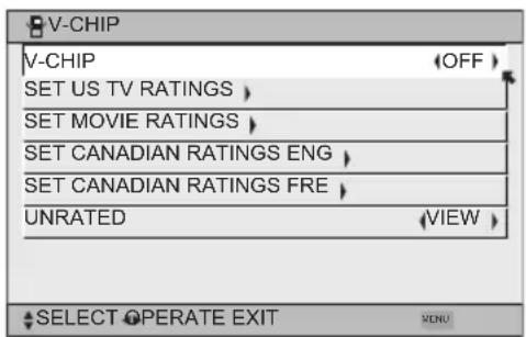
You can customize the V-Chip settings of your television to match your personal tastes. The V-Chip menu below is the starting point for your V-Chip settings
You can use US V-Chip settings (for programming broadcast from the United States), Canadian V-Chip settings (for programming broadcast from Canada), and movie ratings. You may use any or all of the settings (US V-Chip, Canada V-Chip, Movie ratings). Descriptions for setting each of the three V-Chip formats appear in the next six pages along with descriptions of the rating categories.
To access the rating categories:
Press the M
ENU button


To V-CHIP
To operate (Lock icon 📄 will appear)
Press ZERO to access the V-Chip menu
To turn V-Chip ON or OFF (V-Chip must be turned ON for rating settings to operate)
To move to SET US TV RATINGS, SET MOVIE RATINGS, or SET CANADIAN RATINGS (see following pages for descriptions of each item)
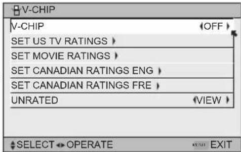
text_image
V-CHIP V-CHIP OFF SET US TV RATINGS SET MOVIE RATINGS SET CANADIAN RATINGS ENG SET CANADIAN RATINGS FRE UNRATED VIEW SELECT OPERATE EXIT VENUInitial Setup
Unrated Programs
Unrated programming refers to any programming which does not contain a rating signal. Programming on television stations which do not broadcast rating signals will be placed in the "Unrated Programming" category.
Examples of Unrated programs:
- Emergency Bulletins
- Locally Originated Programming
- News
- Political Programs
• Public Service Announcements • Religious Programs - Sports
- Weather
• Some Commercials
Note:
- TV programs or movies that do not have rating signals will be blocked if the unrated category is set to BLOCK.
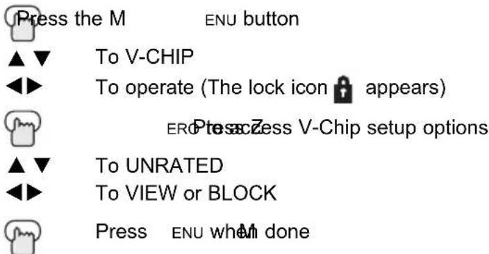
Directions to Block Unrated Programs
You can block programs that are not rated.
text_image
Press the M ENU button ▲▼ To V-CHIP ◀▶ To operate (The lock icon appears) ERD Press to Zess V-Chip setup options ▲▼ To UNRATED ◀▶ To VIEW or BLOCK Press ENU when done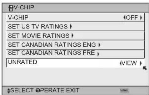
text_image
V-CHIP V-CHIP (OFF) SET US TV RATINGS > SET MOVIE RATINGS > SET CANADIAN RATINGS ENG > SET CANADIAN RATINGS FRE > UNRATED (VIEW) SELECT OPERATE EXIT MENUUS V-Chip Ratings
U.S. PARENTAL RATING SYSTEMS
Programs with the following ratings are appropriate for children.
☐ TV Y is Appropriate for All Children
Programs are created for very young viewers and should be suitable for all ages, including children ages 2 - 6.
TV Y7 is for Older Children
Most parents would find such programs suitable for children 7 and above. These programs may contain some mild fantasy violence or comedic violence, which children should be able to discern from reality.
Programs with the following ratings are designed for the entire audience.
☐ TV G stands for General Audience
Most parents would find these programs suitable for all age groups. They contain little or no violence, no strong language, and little or no sexual dialog or situations.
☐ TV PG Parental Guidance Suggested
May contain some, but not much, strong language, limited violence, and some suggestive sexual dialog or situations. It is recommended that parents watch these programs first, or with their children.
☐ TV 14 Parents Strongly Cautioned
Programs contain some material that may be unsuitable for children under the age of 14 including possible intense violence, sexual situations, strong coarse language, or intensely suggestive dialog. Parents are cautioned against unattended viewing by children under 14.
☐ TV MA Mature Audiences Only
These programs are specifically for adults and may be unsuitable for anyone under 17 years of age. TV MA programs may have extensive V, S, L, or D.
Viewing Guidelines
In addition to the ratings categories explained above, information on specific kinds of content are also supplied with the V-Chip rating. These types of content may also be blocked. The content types are:
| • | V/FV is for VIOLENCE/FANTASY VIOLENCE |
| • | S stands for SEXUAL CONTENT |
| • | L stands for strong LANGUAGE |
| • | D stands for suggestive DIALOG |
Initial Setup
Setting US V-Chip Ratings

ess the MENU button


To V-CHIP


To operate (lock icon 🔒 appears)


To turn V-Chip ON or OFF


To move to SET US TV RATINGS


To operate
text_image
V-CHIP V-CHIP OFF SET US TV RATINGS > SET MOVIE RATINGS > SET CANADIAN RATINGS ENG > SET CANADIAN RATINGS FRE > UNRATED VIEW > SELECT OPERATE EXITDirections to set US V-Chip Ratings
Line up the cursor in the column (TV PG, TV G, etc.) with the content row (V/FV, S, etc.) and press the ▲▼or ◀▶ to move the cursor to the correct location. Press Ok to turn the locking feature on or off. An item is locked if the 🔒 icon appears instead of a “—”.
For example. To block viewing of all TV 14 shows, move the cursor to the top row of that column and add a lock icon. Once you've put a lock on the top row, everything in that column is automatically locked.

To the TV 14 Column


Press the Ok button to lock


Press the
MENU button when fin
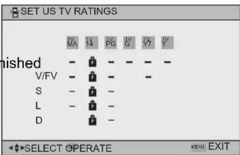
text_image
SET US TV RATINGS MA 14 PG PG G Y Y finished - - - - - V/FV - - - - S - - - - L - - - - D - - - - SELECT OPERATE KERU EXITNote:
- If you want to change the setup, move the cursor to the top column and change the lock icon to “—” by pressing OK again. You may then select individual categories to block.
Movies Ratings
□ NR – Not Rated
This is a film which has no rating. In many cases these films were imported from countries which do not use the MPAA ratings system. Other NR films may be from amateur producers who didn't intend to have their film widely released.
NR (Not Rated) Programming may contain all types of programming including children's programming, foreign programs, or adult material.
□ G – General Audience
In the opinion of the review board, these films contain nothing in the way of sexual content, violence, or language that would be unsuitable for audiences of any age.
PG – Parental Guidance
Parental Guidance means the movie may contain some contents such as mild violence, some brief nudity, and strong language. The contents are not deemed intense.
☐ PG-13 – Parents Strongly Cautioned
Parents with children under 13 are cautioned that the content of movies with this rating may include more explicit sexual, language, and violence content than movies rated PG.
□ R - Restricted
These films contain material that is explicit in nature and is not recommended for unsupervised children under the age of 17.
□ NC-17 – No One Under 17
These movies contain content which most parents would feel is too adult for their children to view. Content can consist of strong language, nudity, violence, and suggestive or explicit subject matter.
☐ X - No One under 18
Inappropriate material for anyone under 18.
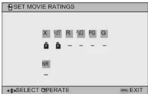
Directions to set Movie (MPAA) Ratings

Press the MENU button

To V-CHIP

To operate (Lock icon 🔒 appears)

ERPtesacZess V-Chip setup options

To SET MOVIE RATINGS

To enter movies menu
For example:
To block viewing of X and NC-17 rated from shows:

To the X Column

Press the Ok button to lock

To the NC-17 Column

Press the Ok button to lock

ENU button to finish
text_image
SET MOVIE RATINGS X Yd7 R Pg3 PG G NR - SELECT OPERATE MENS EXITInitial Setup
Canadian V-Chip Ratings
□ E - Exempt
Exempt programming includes: news, sports, documentaries and other information programming, talk shows, music videos, and variety programming.
C – Programming Intended for Children
Violence Guidelines: There will be no realistic scenes of violence. Depictions of aggressive behavior will be infrequent and limited to portrayals that are clearly imaginary, comedic or unrealistic in nature.
☐ C8+ – Programming Intended for Children 8 and Over
Violence Guidelines: Any realistic depictions of violence will be infrequent, discreet, of low intensity and will show the consequences of the acts. There will be no offensive language, nudity or sexual content.
□ G - General Audience
Programming will contain little violence and will be sensitive to themes which could affect younger children.
PG - Parental Guidance
Programming intended for a general audience, but which may not be suitable for younger children. Parents may consider some content not appropriate for children aged 8-13.
☐ 14+ – 14 Years and Older
Parents are strongly cautioned to exercise discretion in permitting viewing by pre-teens and early teens. Programming may contain mature themes and scenes of intense violence.
□ 18+ - Adult
Material intended for mature audiences only.
Directions to set Canadian V-Chip Ratings

Press the MENU button

To V-CHIP

To operate (lock icon 🔒 appears)

Press ZERO to access V-Chip setup options

To SET CANADIAN RATINGS ENG (for English)

To enter ratings menu
For example:
To block viewing of programming rated 14+ and 18+:

To the 18+ Column

Press the Ok button to lock

To the 14+ Column

Press the Ok button to lock

ess the MENU button to finish
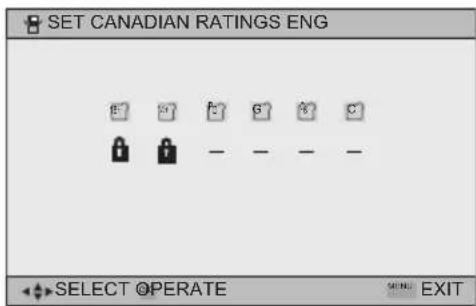
text_image
SET CANADIAN RATINGS ENG SELECT OPERATE SELL: EXITNote:
- For instructions on "SET CANADIAN RATINGS FRE (in French)", please see page 48 in the French side of this user's guide.
Set Lock Code
Channel guard and V-Chip settings are protected by a four-digit lock code. Your TV comes preset with a lock code of "0000". You may change the code to any four-digit number you wish. To change the lock code, follow the steps below.
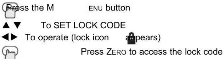
text_image
Press the M ENU button ▲▼ To SET LOCK CODE ◀▶ To operate (lock icon appears) Press ZERO to access the lock codeThe first digit will be highlighted
◀▶ To select the number ▲ ▼To move to the next digit
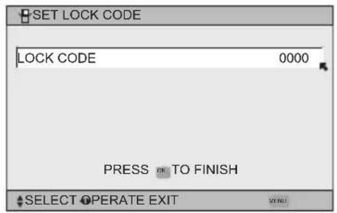
text_image
SET LOCK CODE LOCK CODE 0000 PRESS TO FINISH SELECT OPERATE EXITContinue to follow these directions for all four numbers
Press the OK button to finish (your lock code is now set) Press the Menu button when finished
When a viewer attempts to watch a blocked channel, this message appears:
THIS PROGRAMMING EXCEEDS YOUR RATING LIMITS. PLEASE ENTER LOCK CODE BY 10 KEY PAD TO UNLOCK IT. NO. ----
The channel will remain blocked until the correct lock code is entered (see above for information on setting your lock code).
Notes:
• After a power interruption you must reset the lock code.
- Write your lock code number down and keep it hidden from potential viewers.
- If you forget the lock code, a new code may be set using the steps listed above.
Initial Setup
Language
The language function is described on page 30 as the interactive plug-in menu. If you need to choose the language again, follow the steps below.


Press the Menu button
To LANGUAGE
To choose a language: ENG. (English), FRAN. (French) or ESP. (Spanish)

Press the MENU button when finished
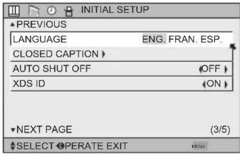
text_image
INITIAL SETUP ▲ PREVIOUS LANGUAGE ENG. FRAN. ESP. CLOSED CAPTION > AUTO SHUT OFF OFF > XDS ID (ON) ▼ NEXT PAGE (3/5) ▲ SELECT OPERATE EXIT NEWClosed Caption
Many broadcasts now include an onscreen display of dialog called closed captions. Some broadcasts may also include displays of additional information in text form. Your television can access and display this information using the closed caption feature. To activate the closed caption feature, follow the steps below. There are three methods. When you are watching analog channels, you can perform Analog Setting of closed caption. When you are watching digital channels, you can perform Digital Auto Setting or Digital Manual Setting.
Analog Setting
Press the MENU button


To CLOSED CAPTION
To enter
To MODE

To select CAPTION or TEXT in MODE

To CAPTION or TEXT

To select a caption (CC1 to CC4) or text channel (T1 to T4)

ss the Ok button to save

ss the MENU button when finished
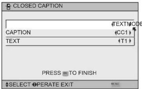
text_image
CLOSED CAPTION TEXTMODE CAPTION (CC1) TEXT (T1) PRESS OK TO FINISH SELECT OPERATE EXITDigital Auto Setting

ess the MENU button

To CLOSED CAPTION

To enter

To Type

To select Auto, Advanced or Basic
Auto: Shows closed caption a priority for digital channels over analog channels. It is set automatically.
Advanced: Shows only the digital closed caption.
Basic: Shows only the analog closed caption.

To Service

To select 1, 2, 3, 4, 5 or 6

To Appearance

To enter

To select Auto

To Set

ess the O κ button to save
The font/type and color are set automatically.

ess the MENU button when finished
Note:
- If you want to cancel the settings, select cancel.
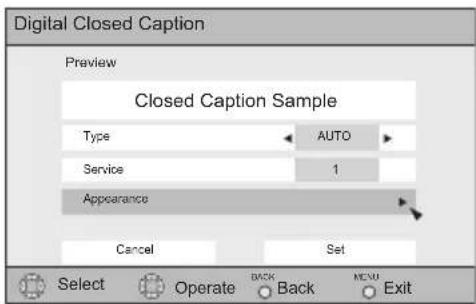
text_image
Digital Closed Caption Preview Closed Caption Sample Type AUTO Service 1 Appearance Cancel Set Select Operate BACK Menu Exit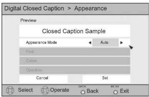
text_image
Digital Closed Caption > Appearance Preview Closed Caption Sample Appearance Mode Auto Font Colors Opacity Cancel Set Select Operate BACK NEMU Back ExitInitial Setup
Digital Manual Setting
Press the M
ENU button

To CLOSED CAPTION

To enter

To Type

To select Auto, Advanced or Basic

To Service

To select 1, 2, 3, 4, 5 or 6

To Appearance

To enter

To select Manual

To Font

To enter

To select Font Size or Font Style

To select the setting you like
Font Size: Auto, Standard, Large or Small
Font Style: Auto, Serif Mono, Serif, Sanserif mono,
Sanserif, Casual, Cursive or Small Capital

To Set

ss the Ok button to save

To Colors

To enter

To select Text, Edge or Background

To select the setting you like
Auto, White, Black, Red, Green, Blue, Yellow, Magenta or Cyan

To Set

ss the Ok button to save

To Opacities

To enter

To select Text/Edge or Background

To select Auto, Transparent, Translucent, Solid. or Flashing

To Set

ss the O κ button to save

ss the M ENU button when finished
Notes:
- Closed caption subtitles are usually found on closed caption channel CC1. Some programs may include additional text information which is usually found on text channel T1. The other channels are available for future use.
- Closed captioning may not work correctly if the signal being received is weak or if you are playing a video tape.
- Most broadcasts containing closed captioning will display a notice at the start of the program.
• To select the mode, press the C.C. button. See page 73. - When ZOOM aspects like PANORAMA or CINEMA are selected, Digital Closed Captions may be cut off or distorted.

text_image
Digital Closed Caption > Appearance Preview Closed Caption Sample Appearance Mode Manual Font Colors Opacities Cancel Set Select Operate Back Exit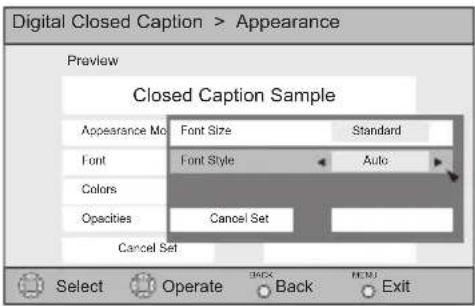
text_image
Digital Closed Caption > Appearance Preview Closed Caption Sample Appearance Mode Font Size Standard Font Font Style Auto Colors Opacity Cancel Set Cancel Set Select Operate Back Exit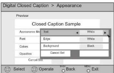
text_image
Digital Closed Caption > Appearance Preview Closed Caption Sample Appearance Mo Text White Font Edge White Colors Background Black Opacity Cancel Set Cancel Set Select Operate Back MEND ExitAll fonts used for digital closed caption and digital menus are licensed from Monotype Imaging
Auto Shut Off
This function automatically shuts off your TV when there is no signal from the channel the TV is on.

Press the M
ENU button

To AUTO SHUT OFF

To turn ON or OFF

Press the M
ENU button when finished
- If the channel that you have on does not receive a signal for more than one minute, the blinking text "NOT RECEIVING A SIGNAL AUTO SHUT OFF IN 9 MIN." appears on the screen, and starts the countdown. If no signal is being received within 10 minutes, the TV shuts itself off.
- When i.LINK is displayed, Auto Shut Off will not work.
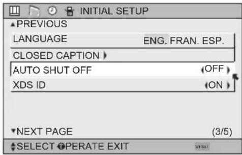
text_image
INITIAL SETUP ▲ PREVIOUS LANGUAGE ENG. FRAN. ESP. CLOSED CAPTION > AUTO SHUT OFF (OFF) XDS ID (ON) ▼ NEXT PAGE (3/5) ▲ SELECT OPERATE EXITXDS ID
XDS ID Display provides a channel's call letters, the network's name, and even a program name. The XDS ID information is provided by the broadcaster.

Press the MENU button

To
XDS
ID

To turn ON or OFF
Press the MENU button when finished
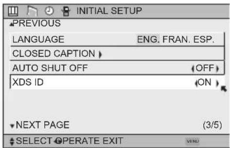
text_image
INITIAL SETUP PREVIOUS LANGUAGE ENG. FRAN. ESP. CLOSED CAPTION AUTO SHUT OFF (OFF) XDS ID (ON) NEXT PAGE (3/5) SELECT OPERATE EXITNoise Muting
This feature inserts a blank gray screen over channels which are not broadcasting or are too weak to be received clearly.

Press the M
ENU button

To NOISE MUTING
To turn noise muting ON or OFF

Press the MENU button when finished
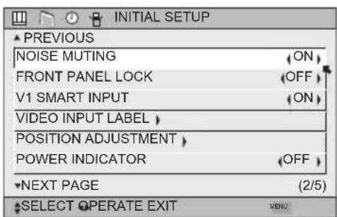
text_image
INITIAL SETUP ▲ PREVIOUS NOISE MUTING FRONT PANEL LOCK V1 SMART INPUT VIDEO INPUT LABEL POSITION ADJUSTMENT POWER INDICATOR NEXT PAGE (2/5) SELECT OPERATE EXIT VENUNotes:
- Noise muting will not work during auto tuner setup or when you operate channel summary.
- Noise muting will not work when the digital TV or i.LINK is displayed.
Initial Setup
Front Panel Lock
This allows you to lock the keys on the side of the TV, so that a child may not accidentally change your viewing preferences.

Press the M ENU button
Press the MENU button when finished
You can turn off this feature in the following ways:
- Unplug the power cord, and plug it back in. Do this if your batteries die, or you lose your remote control.
• Use the remote control. - Press the MENU button on the side of the TV for more than 3 seconds. In this case, the OSD for FRONT PANEL LOCK will appear.
Note:
- To turn ON/OFF the TV, press the power button for more than 3 seconds. This feature will remain ON.
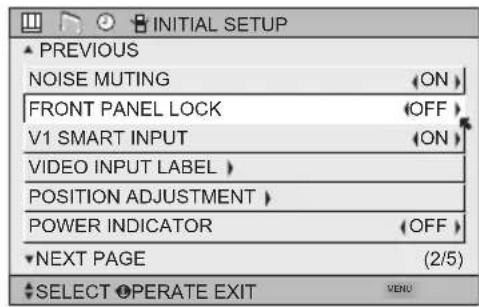
text_image
INITIAL SETUP ▲ PREVIOUS NOISE MUTING FRONT PANEL LOCK V1 SMART INPUT VIDEO INPUT LABEL POSITION ADJUSTMENT POWER INDICATOR ▼NEXT PAGE (2/5) ▼SELECT OPERATE EXIT VENUV1 Smart Input
This feature is used if you have connected an AV Receiver to your television. By turning this feature on, your television can automatically detect the signal source from your components that are connected to your AV Receiver.

Press the M ENU button

To V1 SMART INPUT
To turn ON or OFF

Press the MENU button when finished
Notes:
- If you do not have an AV Receiver connected to your television, turn this feature OFF. By doing so, you can take advantage of using AV CompuLink components with your television.
- Some AV Receivers may not work with this function.
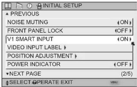
text_image
INITIAL SETUP ▲ PREVIOUS NOISE MUTING (ON) FRONT PANEL LOCK (OFF) V1 SMART INPUT (ON) VIDEO INPUT LABEL > POSITION ADJUSTMENT > POWER INDICATOR (OFF) ▼NEXT PAGE (2/5) ▲ SELECT OPERATE EXIT MENUVideo Input Label
This function is used to label video input connections for the onscreen displays.

Press the M
ENU button

Press the OK button to save

Press the MENU button when finished
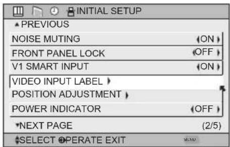
text_image
INITIAL SETUP ▲ PREVIOUS NOISE MUTING FRONT PANEL LOCK V1 SMART INPUT VIDEO INPUT LABEL POSITION ADJUSTMENT POWER INDICATOR NEXT PAGE (2/5) SELECT OPERATE EXIT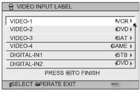
text_image
VIDEO INPUT LABEL VIDEO-1 VCR VIDEO-2 DVD VIDEO-3 SAT VIDEO-4 GAME DIGITAL-IN1 STB DIGITAL-IN2 DVD PRESS OK TO FINISH SELECT OPERATE EXIT| Preset Labels | Select when... |
| VCR | You have a VCR connected to the video input |
| DVD | You have a DVD connected to the video input |
| DVHS | You have a Digital VCR connected to the video input |
| STB | You have a Set-top Box connected to the video input |
| SAT | You have a Satellite Receiver connected to the video input |
| AMP | You have an Amplifier connected to the video input |
| GAME | You have a Video Game connected to the video input |
| CAM | You have a Video Camera connected to the video input |
| DISC | You have a Video Disc player connected to the video input |
Initial Setup
Position Adjustment
Position adjustment allows you to adjust the position of the picture on the screen vertically when the aspect is set to panorama or cinema.

Press the M ENU button
▲▼ To POSITION ADJUSTMENT
◀▶ To enter
▲ ▼▶ To adjust the position
Press the MENU button to finish
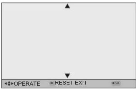
text_image
OPERATE OR RESET EXIT RESUNotes:
- To reset the adjustment to the center, press the Ok button.
- When the arrow disappears, while you are adjusting the position, the position is at its maximum limit.
- If you select REGULAR, SLIM and FULL size with aspect or Multi Screen, position adjustment option is not seen.
- When you change the screen size, perform the position adjustment again.
- Position adjustment allows you to adjust the screen position vertically and horizontally when the aspect is set Panorama Zoom or Cinema Zoom for 1080i and 720p signals, or when PC mode is set.
Power Indicator
Power indicator allows you to adjust the brightness of the power indicator

Press the MENU button

To POWER INDICATOR

To adjust POWER INDICATOR LOW, HIGH or OFF
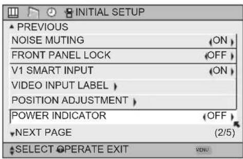
text_image
INITIAL SETUP ▲ PREVIOUS NOISE MUTING FRONT PANEL LOCK V1 SMART INPUT VIDEO INPUT LABEL POSITION ADJUSTMENT POWER INDICATOR NEXT PAGE (2/5) SELECT OPERATE EXIT VENUNotes :
- When OFF is selected :
The LED disappears if you have a TV signal.
The LED is lit as "LOW" when there is no TV signal.
- When the On Timer turns ON, the LED is lit as "LOW" when you turn the power off.
- If you set a timer on the TV, the power indicator will light even if the TV is on stand by.
Video-1 Monitor Out
This function allows you to set whether the signal, which comes from VIDEO-1 input terminal, should be output from MONITOR OUT terminal. If you select it from MONITOR OUT, set it to "ON".

Press the MENU button

To VIDEO-1 MONITOR OUT

To select ON or OFF

Press the MENU button to finish
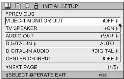
text_image
INITIAL SETUP PREVIOUS VIDEO-1 MONITOR OUT OFF TV SPEAKER ON AUDIO OUT (VARI) DIGITAL-IN AUTO DIGITAL-IN AUDIO DIGITAL CENTER CH INPUT OFF NEXT PAGE (1/5) SELECT OPERATE EXITTV Speaker
If your TV is connected to a stereo system, you can turn off the TV speakers and listen to the audio through your stereo.

Press the MENU button

To TV SPEAKER
To turn the TV's speakers ON or OFF

Press the MENU button when finished
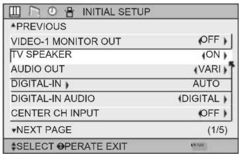
text_image
INITIAL SETUP PREVIOUS VIDEO-1 MONITOR OUT OFF TV SPEAKER ON AUDIO OUT (VARI) DIGITAL-IN AUTO DIGITAL-IN AUDIO DIGITAL CENTER CH INPUT OFF NEXT PAGE (1/5) SELECT OPERATE EXITNotes:
- Before you turn the TV speaker setting from OFF to ON, make sure that the TV volume level is low! If the TV volume is set too high, the sound level will be extremely loud.
- After a power interruption, the TV speaker settings will return to "ON".
Audio Out
If your television is connected to an external speaker source, audio out gives you the option of controlling the volume level with your TV's remote control.

Press the MENU button

To
AUDIO
OUT

To VARI or FIX

Press the M ENU button when finished
VARI: Lets you adjust the volume of the external speakers using the VOLUME+/- buttons on your TV's remote control.
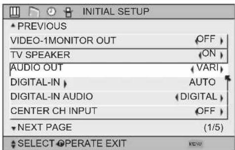
text_image
INITIAL SETUP PREVIOUS VIDEO-1MONITOR OUT OFF TV SPEAKER ON AUDIO OUT VARI DIGITAL-IN AUTO DIGITAL-IN AUDIO DIGITAL CENTER CH INPUT OFF NEXT PAGE (1/5) SELECT OPERATE EXIT MENUFIX: The volume of the external speakers is adjusted using the audio device's remote control.
Note:
• After the TV has been turned off, the sound from the audio out terminal continues to output sound for 5 seconds. After 5 seconds, it stops outputting sound.
Initial Setup
Digital-In
The DIGITAL-IN option can only be displayed in the INITIAL SETUP menu when an HDMI480p picture signal is being input to the DIGITAL-IN terminal. This option adjusts the position when an HDMI or DVI 480p picture signal is being displayed on the screen. There are two types of HDMI480p picture signals: 640x480 and 720x480. If the displayed picture is slightly shifted, the position can be adjusted by selecting either SIZE1 or SIZE2.

Press the M ENU button

▼To DIGITAL-IN

To enter

▼To select AUTO, SIZE1 or SIZE2

Press the M ENU button to finish
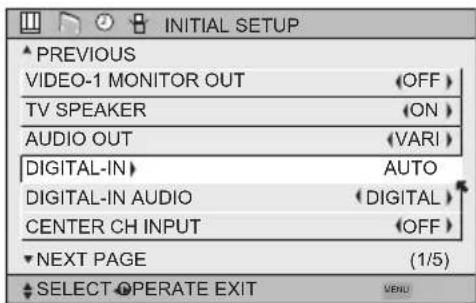
text_image
INITIAL SETUP PREVIOUS VIDEO-1 MONITOR OUT OFF TV SPEAKER (ON) AUDIO OUT (VARI) DIGITAL-IN AUTO DIGITAL-IN AUDIO (DIGITAL) CENTER CH INPUT (OFF) NEXT PAGE (1/5) SELECT OPERATE EXIT MENUNotes:
- The DIGITAL-IN menu can only be displayed when a HDMI or DVI 480p picture signal is input to the Digital-In terminal and the picture is being displayed on the screen.
- You can select AUTO only when the signal is 480p for HDMI. When you select AUTO, the television will select "SIZE1" or "SIZE2" automatically.
Digital-In Audio
This feature is used if you have a DTV or HDMI compatible component connected to your TV.

ess the MENU button

To DIGITAL-IN AUDIO

To select ANALOG, DIGITAL or AUTO

Press the Menu button when finished
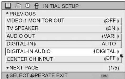
text_image
INITIAL SETUP PREVIOUS VIDEO-1 MONITOR OUT OFF TV SPEAKER ON AUDIO OUT VARI DIGITAL-IN AUTO DIGITAL-IN AUDIO DIGITAL CENTER CH INPUT OFF NEXT PAGE (1/5) SELECT OPERATE EXIT MENUNotes:
- If your DTV or HDMI component is capable of digital audio and video, choose DIGITAL. If your DTV or HDMI
component is capable of analog audio and digital video, choose ANALOG. - Refer to your DTV or HDMI component's instruction manual for more information.
- When you select AUTO, the television will select "ANALOG" or "DIGITAL" automatically, depending on the audio input from the HDMI.
- When you select DIGITAL, select PCM on Digital Sound in the Digital Setup menu. See page 79.
- When your input is DIGITAL-IN2, DIGITAL-IN AUDIO cannot be selected.
Center CH Input
When you are using a surround system, you can substitute the speaker of this television for the center speaker of your surround system. Set CENTER CH INPUT to ON when you use the speaker as the center speaker of your surround system. The volume differs when the TV is being utilized as the Center Channel Input versus when it is not.

Press the M ENU button

To CENTER CH INPUT

To adjust CENTER CH INPUT to ON or OFF

Press the M ENU button when finished
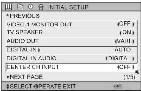
text_image
INITIAL SETUP PREVIOUS VIDEO-1 MONITOR OUT OFF TV SPEAKER (ON) AUDIO OUT (VARI) DIGITAL-IN AUTO DIGITAL-IN AUDIO (DIGITAL) CENTER CH INPUT (OFF) NEXT PAGE (1/5) SELECT OPERATE EXITNote:
- In order to use the CENTER CHANNEL SPEAKER feature, you need a video signal present as well as sound. Because of that we recommend using this feature for Home Theater setup only. If there is no video signal present, the TV will be muted.
- There are two different volume adjustment levels, one for regular TV and one for TV used as a CENTER CHANNEL. Please remember that when switching CENTER CHANNEL mode ON and OFF in TV menu.
Picture Adjust
Picture Settings
These settings allow you to change and adjust the way the picture appears on your television.
TINT
Tint allows you to adjust the levels of red and green in your TV picture.
COLOR
The color function lets you make all the colors in the TV picture appear either more vivid or subtle.
PICTURE
Picture allows you to adjust the levels of black and white on the TV screen, giving you a darker or brighter picture overall.
BRIGHT
You can adjust the overall brightness of the TV picture with the Bright control.
DETAIL
The Detail feature adjusts the level of fine detail displayed in the picture.
Adjust the Picture Settings


Press the MENU button
To TINT, COLOR, PICTURE, BRIGHT or DETAIL

To enter To adjust the setting
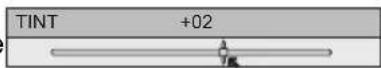
▲ ▼To move to the next setting

Press the MENU button when finished
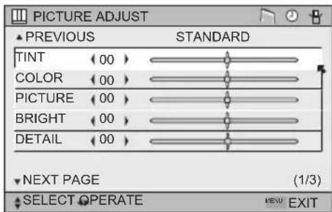
text_image
PICTURE ADJUST ▲ PREVIOUS STANDARD TINT (00) COLOR (00) PICTURE (00) BRIGHT (00) DETAIL (00) NEXT PAGE (1/3) SELECT OPERATE MENU EXITNote:
- There are four video status settings: Dynamic, Standard, Theater and Game. Each video status setting has a separate memory for HD (1080i/720p) and SD (480p/480i) video signal. Each video status can be chosen along with your favorite picture settings (Tint, Color, Picture, Bright, Detail, etc.) See page 71 for details.
Color Temperature
You can decide how strong or dull the colors appear on the TV screen.

Press the M ENU button

To COLOR
TEMPERATURE

To enter
▲▼To set LOW or HIGH

Press the M ENU button when finished
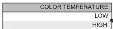
Note:
• Although you can choose LOW or HIGH, they have the same effect on the TV picture.
Picture Adjust
Color Management
This TV supports the COLOR MANAGEMENT function to ensure dull colors are compensated to produce natural hues.
Press the M ENU button
▲▼To COLOR MANAGEMENT
◀▶ To enter
▲▼ To select the mode "ON" or "OFF"
Press the M ENU button when finished
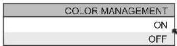
Dynamic Gamma
JVC's Dynamic Gamma Circuitry (DGC makes it easier to see dark areas when a picture has many dark areas, and makes it easier to see the bright areas when a picture has many bright areas. DGC is turned on, DGC analyzes and adjusts the total level of picture brightness balance, especially in dark areas where the level of grayscale is often lost, turning completely to black DGC automatically enhances the detail in these dark areas providing a more dynamic image with finer detail, so the optimum picture settings are automatically set for each picture. Normally use with DGC on.
Press the MENU button
▲▼To DYNAMIC GAMMA
◀▶ To enter
▲ ▼To turn ON or OFF
Press the MENU button when finished
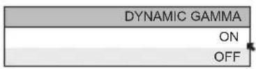
Smart Picture
Smart Picture detects the APL (Average Picture Level) and adjusts the contrast suitable for what you are watching.
Press the MENU button
▲ ▼To SMART PICTURE
◀▶ To enter
▲ ▼To select the mode "ON" or "OFF"

Press bottom when finished
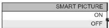
Note:
- When you have "DYNAMIC" selected in the "VIDEO STATUS", Smart Picture is not selected.
Picture Adjust
Digital VNR
This function can be selected to change the effect of Digital VNR (Video Noise Reduction).
Press the M ENU button
▲▼To DIGITAL VNR
◀▶ To enter
▲ ▼To select the effect you like.
AUTO: adjusts the effect of VNR automatically.
MIN: adjusts the effect of VNR to minimum.
MAX: adjusts the effect of VNR to Maximum.
OFF: turns the effect of VNR off.
| DIGITAL VNR |
| AUTO |
| MIN |
| MAX |
| OFF |
Press the MENU button when finished
MPEG NR
This function effects the blocks noise removal and mosquito NR (Noise Reduction) simultaneously.
Press the M ENU button
▲▼To MPEG NR
◀▶ To enter
▲ ▼To select ON or OFF.

Press button when finished
| MPEG NR |
| ON |
| OFF |
Reset
Reset resets all picture adjustments (tint, color, picture, bright, detail, color temperature, Color Management, Dynamic Gamma, Smart Picture, Digital VNR and MPEG NR) at once to the default settings.
Press the M ENU button ▲▼ To RESET ◀▶ To enter
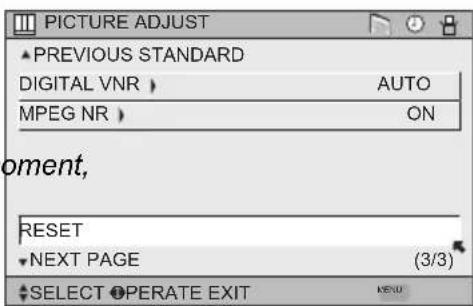
text_image
PICTURE ADJUST ▲ PREVIOUS STANDARD DIGITAL VNR > AUTO MPEG NR > ON oment, RESET ▼ NEXT PAGE (3/3) ▲ SELECT OPERATE EXIT MENUThe onscreen menu disappears for a moment, and then the settings are reset to the default setting for all the picture adjustments.
Press the MENU button when finished
Sound Adjust
Sound Settings
These settings allow you to change and adjust the sound on your television.
BASS – You can increase or decrease the level of low-frequency sound in the TV's audio with the bass adjustment.
TREBLE – Use treble to adjust the level of high-frequency sound in your TV's audio.
BALANCE – Adjust the level of sound between the TV's left and right speakers with the balance setting.
Adjust the Sound Settings
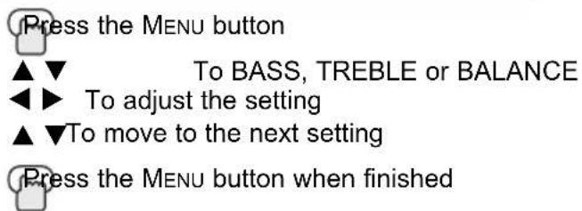
text_image
Press the MENU button ▲▼ To BASS, TREBLE or BALANCE ◀▶ To adjust the setting ▲▼To move to the next setting Press the MENU button when finished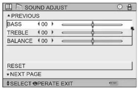
text_image
SOUND ADJUST ▲ PREVIOUS BASS (00) TREBLE (00) BALANCE (00) RESET ▼ NEXT PAGE ♦ SELECT OPERATE EXITNote:
- You can reset the sound adjustments (BASS, TREBLE and BALANCE) you set at once as the default setting when you select reset. See page 62.
- You can adjust BALANCE only when A.H.S.+ is off. See page 70.
Reset
Reset resets all Sound Adjustments (Bass, Treble and Balance) at once to the default settings. See page 62 on how to use reset.
Clock/ Timers
Set Clock
The set clock function is described on page 31 as the interactive plug-in menu. You can choose to set the clock automatically or manually. If you need to set the clock again, follow the steps below.
Press the MENU button


To
To
SET
enter
CLOCK
When you set the clock automatically, choose AUTO by pressing the ◀ or ▶ arrows.
▲▼ To TIME ZONE
◀▶ To select your time zone

▲ ▼To D.S.T. (daylight savings time)
◀▶ To turn D.S.T. ON or OFF
Press OK to finish
Press the MENU button when finished
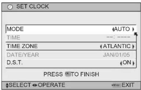
text_image
SET CLOCK MODE(AUTO) TIME--- TIME ZONE(ATLANTIC) DATE/YEAR JAN/01/05 D.S.T. (ON) PRESS OK TO FINISH SELECT OPERATE NEW EXITWhen you set the clock manually, choose MANUAL by pressing the ◀ or ▶ arrows.
▲▼ To move to the hours
◀▶ To set the hours
▲▼ To move to minutes
◀▶ To set the minutes
▲▼ To TIME ZONE
◀▶ To select your time zone:
(Atlantic, Eastern, Central, Mountain, Pacific,
Alaska or Hawaii)
▲▼ To DATE/YEAR
◀▶ To set the month
▲▼ To day
◀▶ To set the day
▲▼ To year
◀▶ To set the year
▲ ▼To D.S.T. (daylight savings time)
◀▶ To turn D.S.T. ON or OFF
Press OK to start clock
THANK YOU !!
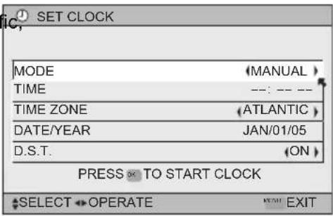
text_image
SET CLOCK MODE (MANUAL) TIME ---: --- -- TIME ZONE (ATLANTIC) DATE/YEAR JAN/01/05 D.S.T. (ON) PRESS ✗ TO START CLOCK SELECT OPERATE HOME EXITPress the MENU button when finished
Notes:
• D.S.T. can be used when it is set to ON in the SET CLOCK menu.
- Only when the MODE set to AUTO, the Daylight Savings Time feature automatically adjusts your TV's clock for Daylight Savings. The clock will move forward one hour at 2:00 am on the first Sunday in April. The clock will move back one hour at 2:00 am on the last Sunday in October.
- You will have to reset the clock after a power interruption. You must set the clock before operating any timer functions.
On/Off Timer
The on/off timer lets you program your television to turn itself on or off. You can use it as an alarm to wake up, to help you remember important programs, or as a decoy when you're not home.

ss the M
ENU button

To ON/OFF TIMER

To enter (begins with ON TIME)

To set the hour (AM/PM) you want the TV to turn on

move to minutes

To set the minutes
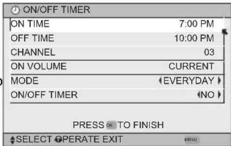
text_image
ON/OFF TIMER ON TIME 7:00 PM OFF TIME 10:00 PM CHANNEL 03 ON VOLUME CURRENT MODE (EVERYDAY) ON/OFF TIMER (NO) PRESS OK TO FINISH SELECT OPERATE EXIT KERU
To accept ON TIME and move to OFF TIME (the time the TV will turn off). Set the ME the same way as ON TIME

accept OFF TIME and move to CHANNEL

To select channel

ON VOLUME

To set the volume level

move to MODE

Choose ONCE or EVERYDAY

To
ON/OFF
TIMER

Choose YES to accept the timer setting, choose NO if you don't wish to accept

ss the OK button to finish

ss the MENU button to exit the menu
Notes:
- The on/off time cannot be set to locked or guarded channels.
- In order for the on/off timer to work, the clock must be set.
• After a power interruption, the timer settings must be reset.
Clock/ Timers
Lamp Timer Reset
The lamp replacement message will appear when you need to change the lamp. After you replace the lamp, you need to reset the timer which is built into your television.

ess the M
ENU button

To LAMP TIMER RESET

To Enter
The following message will appear.
PRESS OK TO RESET THE LAMP TIMER.
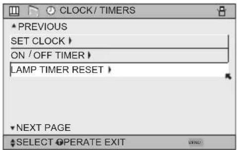
text_image
CLOCK / TIMERS PREVIOUS SET CLOCK > ON / OFF TIMER > LAMP TIMER RESET > NEXT PAGE SELECT OPERATE EXIT
Press the OK button while the above message appears on the television screen.
THE LAMP TIMER IS RESET SUCCESSFULLY.
The lamp timer has now been reset.
Notes:
- You can use the Lamp Timer Reset only after replacing the lamp.
• See Page 98 for instructions on lamp replacement.
Button Functions
Multi Screen Function
Your television has two kinds of screen: TWIN (2 channels) and INDEX (12 channels).
Note: After you press any multiscreen buttons, if you press the menu button, only the picture adjust screen will appear.
Twin
Activate the split-screen option by pressing TWIN on the remote control. The channel (or input) you were watching before pressing TWIN will appear on the left, the new channel will appear on the right. The sound will continue to come from the main screen channel (or input). To turn split-screen off and return to normal television viewing, press TWIN again or press the BACK button.
| 07 | V-1 |
| MAIN SCREEN PICTURE | SPLIT SCREEN PICTURE |
Notes:
- If the signal that you are watching is coming from the HDMI input, you cannot enter the SWAP or INDEX mode.
- Main Screen and Split Screen will not display the same channel or input at the same time.
- You can enter the TWIN mode when the screen is in NORMAL or INDEX mode.
- Split screen will not display digital channels.
- Split-screen functions will not work with locked channels or channels blocked by V-Chip ratings limits. A gray screen will display instead.
- With split screen, the picture from the component terminal and DIGITAL-IN terminal will not be displayed.
- The aspect of MAIN CHANNEL PICTURE becomes 16:9 when you input the picture of 480p, 720p and 1080i from the component terminal and DIGITAL-IN terminal.
- After you press the SELECT button, and select SPLIT SCREEN when you press the OK button, select normal screen. If you don't operate, the MAIN CHANNEL SCREEN will be automatically selected about 8 seconds later.
- Aspect does not work in Twin mode.
- When the cable card is inserted into the TV, the combination of analog broadcasting and digital broadcasting will not appear in the TWIN mode.
- When it is PC output, Main and Split screen will not be displayed.
- When you are in PC mode, TWIN, INDEX or FREEZE can not be used.
- When you press the Menu button in Twin mode, it appears only as Picture Adjust menu.
Button Functions
Index
This allows you to quickly look at up to 12 channels at a time so that you can decide which one to watch.
| 1 | 2 | 3 | 4 |
| 5 | 6 | 7 | 8 |
| 9 | 10 | 11 | 12 |
Notes:
- Only Analog Channel input signal will be displayed.
- You can watch the channel added in channel summary. See page 41.
Freeze
Pressing the FREEZE button causes the screen to change to the split-screen display with the still picture displayed on the right. In order to return to the normal display, press the FREEZE button once again.
Swap
You can exchange the channel (or input) displayed in the split screen window for the main screen image by pressing the SWAP button.
Note:
- It will only work in TWIN mode.
Select
With SELECT, you can select the picture (channel) while viewing TWIN screen. When you press SELECT button, the channel number on the top will be highlighted. Each press of SELECT will shift the channel.
Button Functions
Power
Turns the TV on or off.

ess the P
OWER button
Note:
• After turning the power on, you can not turn the power off for about one minute.
Number Buttons - 10Key Pad
Use the number buttons on the remote control to move directly to a specific channel. For example, to move to channel 12:

0
(Zero)

1
(One)

2
(Two)
Tune
Lets you decide the input channel and select it. After you press the number buttons on the remote, press the TUNE button. For example, to move to channel 12:

1
(One)

2
(Two)

Press
UNE thetton
T
Input
Selects the signal input source for the television: VIDEO-1, 2, 3, 4, DIGITAL-IN1, DIGITAL-IN2, or i.LINK for video devices like VCRs, DVD players or camcorders.

ss the I
NPUT button
By every press of the I
NPUT button, you can change the input mode.
Notes:
- When you return to TV mode, press the RETURN +/TV button or direct 10 key pad or CHANNEL +/- button.
- You can also access by pressing the INPUT button on the side of the TV instead of the remote control.
- i.LINK can be selected only when you have an i.LINK device connected.
- If you have a PC connected to the TV, select VIDEO-3.
TheaterPro D6500K
The TheaterPro D6500K color temperature technology function makes sure that the video you watch is set to the standard color temperature, so that what you see is as true to what the film to video editors intended it to be.

Press
the
THEATERPRO button
Button Functions
Return +/TV
The RETURN+/TV button has three functions:
Return - Returns to the channel viewed just before the channel currently onscreen.
Return+ - Lets you program a specific channel to return to while scanning through the channels using the CH+ and CH- buttons.
TV - Returns to the TV mode.

less the RETURN+/TV and hold for three seconds
RETURN CHANNEL PROGRAMMED!
The channel currently active has been programmed as your return+ channel. Now scan through the channels using the CHANNEL+/- buttons.

ess the RETURN+/TV
You will return to your programmed channel.
- To cancel your return+ channel, press and hold the RETURN+ button for three seconds. The message "RETURN CHANNEL CANCELLED!" will appear.
- Return+ works only with the Channel+/− buttons. Pressing any number key will cancel return+.
Sound
By pressing the SOUND button, you can change the A.H.S.+ (Advanced Hyper Surround plus) mode, BBE, SMART SOUND and HYPER BASS on or off.
A.H.S.+ - Adds a more spacious surround sound. Music gives basic effect and movie for more effect.
BBE - BBE High Definition Sound restores clarity and presence for better speech intelligibility and musical realism.
SMART SOUND - Decreases high sound levels, giving a regulated sound level.
HYPER BASS - Increases bass levels, giving a richer, deeper bass.

ess the S
OUND button

To select A.H.S.+, BBE, SMART SOUND or HYPER BASS

To choose the setting

s the M
ENU when finished
Manufactured under license from BBE Sound, Inc. Licensed by BBE Sound, Inc. under USP4638258, 5510752 and 5736897. BBE and BBE symbol are registered trademarks of BBE Sound, Inc.
Note: Smart Sound may become an unnatural effect, depending on the signal source.
Button Functions
Video Status
The VIDEO STATUS button gives you a choice of four TV picture display settings, including a display of your own preferences.
Standard - Resets the picture display to the factory settings.
Dynamic - Gives a vivid picture with better contrast when viewing in a brightly lit room.
Theater - Gives a rich, film-like look to video when viewing in a dimly lit room.
| VIDEO STATUS |
| STANDARD |
| DYNAMIC |
| THEATER |
| GAME |
Game - Used for when you are playing video games connected to your TV.

ess the VIDEO STATUS button
By every press of the VIDEO STATUS button, you change the mode.
Note:
- You can also change the mode by pressing the ▲▼ buttons.
- You can also access the FRONT CONTROL PANEL screen by using the MENU button on the side of the TV instead of the remote control. It appears between INITIAL SETUP and PICTURE ADJUST screen, and it has VIDEO STATUS and ASPECT menus. Choose VIDEO STATUS by pressing MENU ▼ on the side panel and choose a mode by using the CHANNEL +/- buttons ( ◀ OPERATE ▶ ).
-
There are four video status settings: Dynamic, Standard, Theater and Game. Each video status setting has a separate memory for HD (1080i/720p) and SD (480p/480i) video signal. Each video status can be chosen along with your favorite picture settings (Tint, Color, Picture, Bright, Detail, etc.)
-
When an HD signal is displayed: Your HD settings are recalled for the video status you are using.
- When an SD signal is displayed: Your SD settings are recalled for the video status you are using.
- The input you are using (Input-1, Input-2, etc.) does not affect the setting that is recalled, just the signal type.
- This function considers PC input as an HD signal and PIP and TWIN screens as an SD signal.
Natural Cinema
Natural cinema corrects the problem of blurred edges which may occur when viewing a program originally shot on film (such as motion pictures) or animation. If you notice blurring at the edges of these programs, press NATURAL CINEMA and set it to AUTO. Natural Cinema helps correct conversion errors that occur when film, which is shot at 24 frames-per-second, is broadcast at the television rate of 30 frames-per-second.

Press the NATURAL CINEMA button
Notes: The natural cinema mode is automatically set to "AUTO" in the following cases:
- Turning on or off
- Changing the channel or input mode
• Using multi-screen functions - If you are in PC mode, Natural Cinema can not be used
| NATURAL CINEMA |
| AUTO |
| ON |
| OFF |
Button Functions
Muting
The MUTING button instantly turns the volume down completely when you press it. Press MUTING and the volume level will instantly go to zero. To restore the volume to its previous level, press MUTING again.
Sleep Timer
The Sleep Timer can turn the TV off for you after you fall asleep. Program it to work in intervals of 15 minutes, for a total time of up to 180 minutes.

ess the S
LEEP button

text_image
0 15 30 45 60 75 90 105 120 135 150 165 180Sleep Timer Message
60 seconds before the automatic shutoff, this message will appear:
You then have 60 seconds to press the SLEEP button to delay the shut off for another 15 minutes.
ML/MTS
MTS technology allows several audio signals to be broadcast in analog at once, giving you a choice in what you wish to hear with a TV program. In addition to mono or stereo sound, an MTS broadcast may also include a second audio program (SAP).

ess the ML/M
ts button
By every press of the ML/MTs button, you change the mode
| MTS | |
| ON AIR | STEREO |
| ON AIR | SAP |
| MONO |
Notes:
- When you are receiving a digital broadcast, if there are other languages, you can change the language by pressing the ML/MTS button.
- Keep the TV in stereo mode to get the best sound quality. The sound will work in stereo mode even if a certain broadcast is in mono sound only.
- Choose the mono setting to reduce excessive noise on a certain channel or broadcast.
- Selecting SAP will allow you to hear an alternative soundtrack, if one is available.
- MTS unavailable if your television's Input source is in VIDEO-1, 2, 3, 4, DIGITAL-IN1 or DIGITAL-IN2 mode, as described on page 69.
- ML/MTS will not work when you are using the Digital-In.
- You can also change the mode by pressing the ▲ ▼ buttons.
Button Functions
Display
The display screen shows the current status of timers, inputs and XDS ID.

ss the D
ISPLAY button
The screen to the right shows the following information:
• The current channel or AV input (Channel 05)
• The current time (12:20 pm)
- Sleep timer status/minutes remaining (The Sleep Timer is off)
- On/off timer status (Set to turn on everyday at 7:00 PM, off at 10:00 PM)
• Each Press of the DISPLAY button changes the display mode:
flowchart
graph LR
    A["Display Time"] --> B["Channel Off"]
    B --> C["End"]
Display - Full screen shown above
Time - Shows the current time only
Channel - Shows the current channel
Off - Turns display off
Notes:
- You may also turn off the display at any step by pressing MENU.
- If the clock, sleep timer or on/off timer are not set, the display screen will show: "CLOCK NOT SET", "SLEEP TIMER OFF", and "ON/OFF TIMER OFF" respectively.
C.C. (Closed Caption)
Use the C.C. (Closed Caption) button to select the mode of closed caption.

ess the C.C. button
Notes:
- SMART CAPTION will appear when you press the MUTING button, only on channels where the broadcast contains closed captioning.
- When you select ON, it will be the mode selected in the Closed Caption Menu.
• See page 50 when you set the caption/text mode. - You can also change the mode by pressing the ▲▼buttons.
- If you are in PC mode, C.C. can not be used
| CLOSED CAPTION |
| OFF |
| SMART CAPTION |
| ON |
Channel +/-
Use these buttons to move up or down all the available channels your TV is able to receive.
Volume +/-
Use these buttons to raise or lower the TV's volume level.
Button Functions
Favorite
The Favorite button allows you to select your favorite channels easily. First, you must register the channels that you like. See how to register below.

AVORITE button
The favorite channel list will appear.

To select the channel you want to watch

ss the Ok button
It will change to the channel you have selected.
Register the favorite channel
Press the channel number you want to register
The channel program will change.

ss the F
AVORITE button for three seconds
The channel will be registered in the favorite channel list.
| FAVORITE | |
| ▲ PREVIOUS | |
| 101 | CBS |
| 102 | FOX |
| D103 | PBS2 |
| < | > |
| D107 | HBO |
| 8 | ABC |
| ▼ NEXT | |
Notes:
- Both analog and digital channels can be registered. The digital channels have a "D" in front of the channel number.
- The maximum number of channels you can register is 24.
- If you have registered the maximum number of channels, and try to register more channels, the oldest channel you registered will be deleted.
- Sub channels can not be registered.
- The newest channel you registered will appear at the top of the list.
- Regarding digital channels, see pages 78 - 80.
Delete the favorite channel
Press the FAVORITE button
The favorite channel list will appear.

To select the channel you want to delete
To enter

ss the Ok button
The channel was deleted.

ess the F
AVORITE button when finished
Note:
- Before pressing the FAVORITE button when you are finished, press the ◀▶ button again, and you can return to the deleted channel.
Button Functions
Aspect
This feature will help you adjust the picture you are watching to give you the best possible picture quality.
Aspect Ratios
PANORAMA - With this ratio a normal 4:3 aspect picture is stretched to fit the dimensions of the 16:9 aspect screen.

natural_image
Diagram showing two panels of balloons with one being shifted, no text or symbols presentCINEMA - This ratio "zooms in" on the center part of a 4:3 aspect picture, blowing it up to fill the 16:9 screen.

natural_image
Two-panel image showing a magnified view of balloons on the left and a simplified view of them on the right (no text or symbols)FULL - This is the ratio to use when watching 16:9 High-Definition broadcasts.

natural_image
Two panels showing floating balloons with one being shifted, no text or symbols presentPANORAMA ZOOM - This ratio stretches the High-Definition 16:9 aspect image to eliminate the black side bars.

natural_image
Two-panel image showing a transformation of balloons from left to right, with no text or symbols present.CINEMA ZOOM - This ratio stretches the High-Definition 16:9 aspect image to eliminate the black surrounding bars.

natural_image
Two-panel image showing a magnified view of floating spheres, one larger and smaller, the other smaller and larger, with no text or symbols present.REGULAR - The regular ratio is used when you want to watch a 4:3 broadcast or recorded program without modifying the original picture to fit the dimensions of your 16:9 screen. The 4:3 picture will fill the screen from top to bottom, while gray bars will appear to fill up the remaining space along the picture's sides. The 4:3 picture will be centered within the boundaries of the 16:9 screen.

SLIM - This aspect mode shrinks the screen of 16:9 to 4:3. There are some programming that is already stretched by mistake at broadcasting companies, so this mode corrects it. Gray side bars will appear.

natural_image
Diagram showing two panels of balloons with one being shifted, no text or symbols presentButton Functions
Aspect Ratios (Continued)

Press
the
ASPECT button
s Bepresting you can change the size.
When you change the aspect ratios, it is different from their broadcast or recorded program.
NTSC, 480i, 480p
HD (1080i, 720p) ATSC (1080i, 720p)
ATSC (480i, 480p)
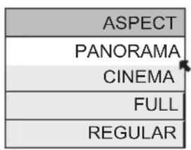
text_image
ASPECT PANORAMA CINEMA FULL REGULAR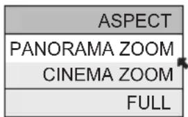
text_image
ASPECT PANORAMA ZOOM CINEMA ZOOM FULL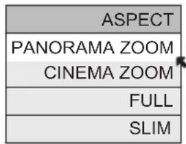
text_image
ASPECT PANORAMA ZOOM CINEMA ZOOM FULL SLIMNotes:
- You can also choose the size by pressing the ▲▼ buttons.
- When you change the aspect ratio or signal, reset the picture position to center.
- You can also access the FRONT PANEL CONTROL screen by using the MNU button on the side of the TV instead of the remote control. It appears between INITIAL SETUP and PICTURE ADJUST screen, and it has VIDEO STATUS and ASPECT menus. Choose ASPECT by pressing Menu ▼ on the side panel and choose a mode by using the CHANNEL +/- buttons ( ◀ OPERATE ▶ ).
- "SLIM" can only be displayed when the signal is ATSC (480i or 480p).
- If the television receives a 16:9 signal from your HDMI device, the aspect mode will turn to FULL automatically. If the television receives a 4:3 signal from your HDMI device when you are in FULL aspect mode, it will return to REGULAR aspect mode. If you change the aspect mode after the television changed it to FULL automatically, the television will change to the aspect mode you chosen.
- If you are in Media Card Viewer mode, Aspect can not be used. (HD-P70R1U Only)
Menu
The MENU button allows you to access JVC's onscreen menu system. Press MENU to activate the onscreen menu system.
- See individual topics like "Sound Adjust" for specific information on using menus.
OK
This button confirms your selection when you are in one of the onscreen menus.
Back
This button allows you to go back in the menu to change a selection or correct a mistake.
Button Functions
TV/CATV Slide Switch
Use either the television's own tuner or a cable box to select channels. Set this switch to TV to operate the television's built-in tuner. Move the switch to CATV to operate a cable box.
Note:
• See page 33 for information on programming your remote for cable box operation.
VCR/DVD Slide Switch
You can control a VCR or DVD player with the buttons on the lower part of the remote control. Move the slide switch to VCR or DVD to operate.
Notes:
- The remote is preset with the code 000 to control JVC-brand VCR's. For any other manufacturer's brand VCR, please see the code chart and instructions on page 34.
- The remote is preset with the code 000 to control JVC-brand DVD players. For any other manufacturer's brand DVD player, please see the code chart and instructions on page 35.
VCR Buttons
You can use this remote control to operate the basic functions of your VCR. These functions include: play, record, rewind, fast-forward, stop, pause, channel scan, TV/VCR, power on and power off.
Move the selector switch to VCR to operate.
- The remote is preset with the code 000 to control JVC-brand VCR's. For any other manufacturer's brand VCR, please see the code chart and instructions on page 34.
DVD Buttons
You can also use this remote control to operate the basic functions of your DVD player. These functions include: play, rewind, fast-forward, stop, still/pause, previous/next, tray open/close, power on and power off.
Move the selector switch to DVD to operate.
- The remote is preset with the code 000 to control JVC-brand DVD players. For any other manufacturer's brand DVD player, please see the code chart and instructions on page 35.
Light
All remote control buttons are illuminated, except for the TV/CATV slide switch, VCR/DVD slide switch and Light button. Press the LIGHT button to turn the illumination on for 4 seconds.
Digital Setup
Digital Setup
Use this function when you are receiving a digital broadcast.

ss the M
ENU button

To DIGITAL SETUP

To enter
The onscreen will appear
Notes:
- Software Update will only appear when the SD Card is inserted.
- If you are watching an analog channel, you can still access the digital setup menu at anytime, while you are doing this, the background screen will turn blank. In this case, the tuner will switch to digital, since you are accessing the digital setup menu.
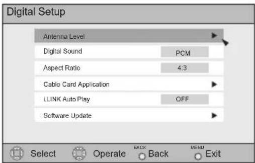
text_image
Digital Setup Antenna Level Digital Sound PCM Aspect Ratio 4:3 Cable Card Application I.LINK Auto Play OFF Software Update Select Operate BACK Back MENU ExitAntenna Level
Confirms the present antenna level.

ss the MENU button

To DIGITAL SETUP

To enter

To Antenna Level

To enter
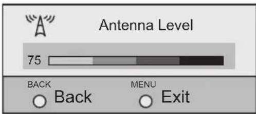
text_image
Antenna Level 75 BACK Back MENU ExitNote:
- If you are watching an analog channel or a signal from your i.LINK device, antenna level will not appear.
Digital Sound
You can select the optical digital sound output, either PCM or Dolby Digital when your TV is connected to an amplifier that has Dolby Digital decoder. If you select Dolby Digital, you can enjoy listening in 5.1ch sound when watching digital broadcasts.

Press thenu button

To DIGITAL SETUP
▲ ▼To Digital Sound
◀▶ To select PCM or DOLBY DIGITAL

Press the MENU button when finished
Notes:
- If your amplifier does not have Dolby Digital decoder, select PCM. If you don't select PCM, it cannot output the sound from the speakers.
- For connecting an amplifier using the optical output, see page 23.

DOLBY
DIGITAL
Manufactured under license from Dolby Laboratories. "Dolby", and the double-D symbol are trademarks of Dolby Laboratories.
Aspect Ratio
You can select the aspect mode for ATSC from 4:3 or 16:9.

ess the MENU button

To DIGITAL SETUP

To enter

To Aspect Ratio

To select 4:3 or 16:9

ess the M ENU button when finished
Notes:
- Set the mode to 4:3 or 16:9 before you record a program using the ATSC MONITOR OUT.
- Make sure the mode you choose is the same as the TV's aspect ratio when the recorded program is played back, so that you can obtain a good picture quality, free from any unnatural distortions.
Digital Setup
Cable Card Application
Press the MENU button

To DIGITAL SETUP

To enter

To Cable Card Application

To enter
Press the Ok button
The application will perform
i.LINK Auto Play
When playing a D-VHS tape, you can set it to the i.LINK input automatically, or manually.
Press the MENU button

To DIGITAL SETUP

To enter

To i.LINK Auto Play

To select ON or OFF
ON: Set to i.LINK input automatically
OFF: Select the input manually

less the MENU button when finished
Software Update
At first, insert the SD(Multi-media) card into the memory card slot. This function will appear only when you insert an SD Card.
Press the MENU button

▼To DIGITAL SETUP

To enter

▼To Software Update

To enter

▼Checks the card if it needs an update or not

ess the MENU button when finished
Digital Button Functions
Digital CH D/A (Digital/Analog)
The D/A button changes the analog and digital channel. Each time you press the D/A button, you can switch back and forth the analog and digital channels. Digital channels have a "D" in front of the channel number.
Note:
- If the cable card is inserted into the TV, you cannot use the D/A button. You can select a digital channel only.
Press the D/A button
To watch digital channels
For example, to move to channel D23:
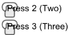

Press
UNE bheton
T
Sub Channel
The main channel sometimes has minor channels (Sub Channels). By using the Sub button, you can select a sub channel easily.
For example, to move to sub channel 123-45:
Press 1 (One)
Press 2 (Two)
Press 3 (Three)
Press the SUB button
Press 4 (Four)
Press 5 (Five)
Press the TUNE button
Note:
- If there are more than 2 major channels, select the digital channel by using the ▲▼buttons and then press the OK button.
Digital Button Functions
i.LINK Menu
i.LINK has two menus - Controller and Device.
By connecting a D-VHS VCR with an i.LINK cable, you can set the timer easily.
Notes:
- The i.LINK/Timer function will only work when you are receiving digital programming only.
- As for the connection of a D-VHS VCR with the i.LINK cable, see page 27.
- When operating the i.LINK, don't insert or disconnect the i.LINK cable.
Controller
You can operate a D-VHS VCR connected with an i.LINK cable by using this controller.
Notes:
- If the i.LINK is not connected, the Controller OSD will not appear. The OSD of device on page 83 will appear.
- Some controller operations may differ from your D-VHS VCR operations.

LINK MENU button
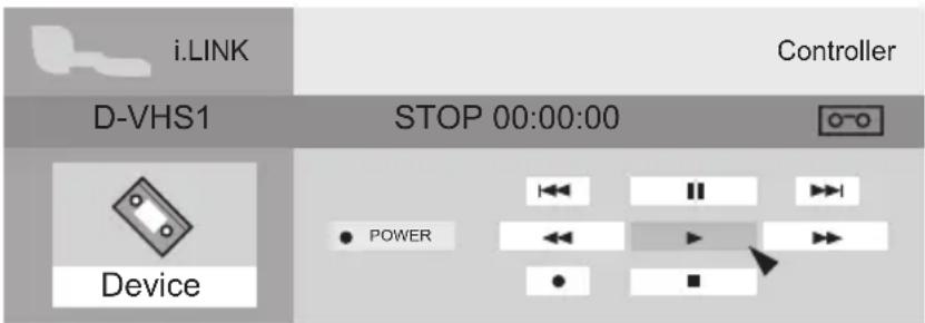
text_image
i.LINK Controller D-VHS1 STOP 00:00:00 Device POWER

▼To select the key you want to operate

ess the Ok button
Digital Button Functions
Device
To operate, select a device.
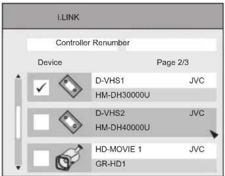
text_image
i.LINK Controller Renumber Device Page 2/3 ✓ D-VHS1 JVC HM-DH30000U ✓ D-VHS2 JVC HM-DH40000U ✓ HD-MOVIE 1 JVC GR-HD1▲ ▼To select your device connecting with i.LINK

ess the OK button
Notes:
- If you do not select the device, you cannot use the i.LINK timer functions.
- When one device is selected and you select controller, you will move to the Controller onscreen.
- The devices listed on the device onscreen are only D-VHS and HD-MOVIE that have i.LINK, which can be recognized on this television. However, you can not record programs to HD-MOVIE.
- If you disconnect one device, it will be removed from the list. Then, select Renumber to rearrange the list in the new order.
Digital Button Functions
Timer
You can set the two timers: Record and view. The timer starts the recording or turns to the channel you set for it automatically.
Reservation

To New Reservation

ss the O
κ button
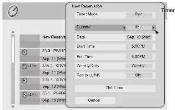
text_image
New Reservation Timer Mode Rec Channel 35-1 Date Sep. 10 (wed) Start Time 5:00PM End Time 6:00PM Weekly/Daily Weekly Rot to LINK ON Set Timer Cancel
To Timer Mode

To select Rec or View

To Channel

To select the channel you want to set the timer for

To Date

To select the date

To Start Time

To set the start time

To End Time

To set end time

To Weekly/Daily

To select Once, Weekly, Daily(Sun.-Sat.), Daily(Mon.-Sat.) or Daily(Mon.-Fri.)

b Rec to i.LINK

To select ON or OFF

To Set Timer

ss the OK button
If you set the Rec on timer mode, set recording R is added in front of the program title.
If you set the View on timer mode, set/viewing is added in front of the program title.
Notes:
- In order for the timer setting to work, you must set the clock on your television. See page 64.
- When you want to edit the timer settings, see Timer Edit on page 85.
Digital Button Functions
Timer Edit
When you want to confirm the timer you set or edited, or delete the timer setting, use this function.
Timer Edition

Press
the
TIMER button
▲ ▼To select the timer list you want to edit
Press the Ok button
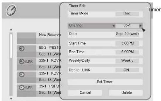
text_image
Timer Edit Timer Mode Rec Channel 35-1 Date Sep. 10 (wed) Start Time 5:00PM End Time 6:00PM Weekly/Daily Weekly Rec to LINK ON Set Timor Cancel Delete New Reserva 50-3 PBS1D Sep. 11 (Wed) 335-1 KDVR Sep. 11 (Wed) 335-1 KDVR Sep. 18 (Wed) 35-1 PBPBP Sep. 18 (Wed)◀▶ ▲ ▼To change the setting you want to edit

To
Set
Timer
Press the Ok button
Timer Deletion

Press
the
TIMER button
▲ ▼To select the timer list you want to delete
Press the Ok button

To
Delete
Press the Ok button
Digital Button Functions
Cancel the timer recording
When you record a digital program now, you can cancel the recording.

Press
IMERtbetton
T

To select the timer list you want to cancel the recording

ess the O
κ button
The message "Do you want to terminate current program ?" will appear.
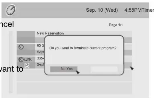
text_image
Sep. 10 (Wed) 4:55PMTimer Page 1/1 New Reservation 80-3 Sept RILINK 335- Sept Do you want to terminate current program? No Yes want to
To select
YES: Cancel the recording
NO: Continue the recording

ess the O
κ button
Guide
You can view the program from the GUIDE.
Notes:
- The GUIDE function will only work when you are receiving digital programming only.
- The GUIDE will not show the correct time and date if you have not performed the set clock function on your television. See page 64.
Media Card Viewer
Note:
• Media Card Viewer is for HD-P70R1U ONLY
Readable Media Card
This TV can read the following media cards:
SD Card, MMC (Multi Media Card), Memory Stick, xD-Picture Card, CF Card (CompactFlash Card), Removable microdrive Hard Disk for JVC digital media camera "Everio" (a type of CF Card)
- Read the cautions on the different types of media cards
- Do not remove a media card if it is being used by the TV. A malfunction may cause the card not to operate properly. JVC shall not provide any compensation for any lost content.
- SM Card (Smart Media Card) is not supported.
- CF Card and removable microdrive Hard Disk for JVC "Everio" camera is a type of CF Card compliant with CF+ Type II.
Supported Card Media
The following media are supported in this unit.
(As of September 2005)
| Microdrive compact hard disks | Hitachi | 2GB, 4GB | * Hard disks with 1GB or smaller capacity are not supported. |
| SD Memory Cards | Panasonic | 128MB, 256MB, 512MB, 1GB | |
| LEXAR | 128MB | ||
| SanDisk | 32MB, 64MB, 128MB, 256MB | ||
| CompactFlash Cards | LEXAR | 512MB, 1GB | |
| xD-Picture Cards | OLYMPUS | 256MB | |
| Fujifilm | 32MB, 64MB, 128MB | ||
| Memory Sticks | SONY | 64MB, 128MB | * Memory Stick PRO cards are not supported. |
Notes:
- Operation is not guaranteed for other card media. Usage of other card media can result in the loss of data already recorded on the card.
- Playback of MPEG-2 video on CompactFlash cards requires a high-speed type card.
- Conversion adapters for card media are not supported.
- The unit may have trouble detecting certain cards. In this case, leave the card inserted, and turn the power off and then on again.
- Recognition of the card can take significantly more time if the card contains a large number of files.
* The above supported card media have been confirmed to work with this TV. However, they are not guaranteed to work with your cards.
Media Card Viewer
How to insert Media Card
Before you insert a media card into the card slot, open the door on the front panel and make sure of the slot type and the direction to insert the card as illustrated. To access, gently pull the tab on the door to open it. Once you have inserted the media card, the message "PLEASE CLOSE THE DOOR TO OPERATE" will appear on the screen. Then, close the door. To remove the media card, press the card into the slot again after opening the door.
Close door when using media cards
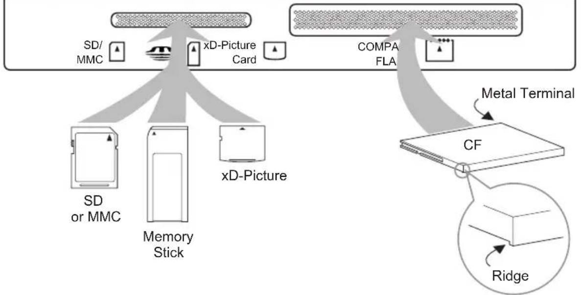
flowchart
graph TD
    A["SD/MMC"] --> B["xD-Picture Card"]
    C["SD or MMC"] --> B
    D["Memory Stick"] --> B
    E["xD-Picture"] --> B
    F["COMPA FLA"] --> G["CF"]
    H["Ridge"] --> I["Metal Terminal"]
    style A fill:#f9f,stroke:#333
    style C fill:#f9f,stroke:#333
    style D fill:#f9f,stroke:#333
    style E fill:#f9f,stroke:#333
    style F fill:#ccf,stroke:#333
    style G fill:#ccf,stroke:#333
    style H fill:#cfc,stroke:#333
    style I fill:#fcc,stroke:#333
*Removable Microdrive Hard Disk does not have a ridge.
Note:
- If you do not close the door, it will not operate.
How to operate Media Card Viewer

Press the M
ENU button

To MEDIA CARD VIEWER

To enter

To select SD Card or COMPACT FLASH card
If you only have one media card inserted in the card slot, this menu will not appear.
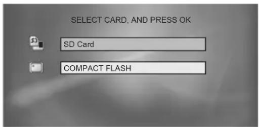
text_image
SELECT CARD, AND PRESS OK SD Card COMPACT FLASH
To enter
The following PHOTO, VIDEO or FILE will appear
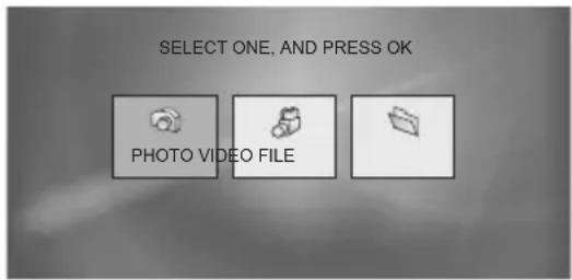
text_image
SELECT ONE, AND PRESS OK PHOTO VIDEO FILE◀▶ To select PHOTO, VIDEO or FILE (Continue to page 90 - 91)
Notes:
- The above screen will change depending on the type of card you insert.
- The sound from the media card can not be changed.
- Onscreen language is linked to LANGUAGE in the Initial Setup Menu.
- When the media card viewer function is used, the menu is not used.
-
The following message appears on the TV screen in the following cases:
-
When you are inserting a media card or when the door is open, "PLEASE CLOSE THE DOOR TO OPERATE".
- When no media card is inserted "NO MEDIA DETECTED"
- When no files are found on the media card "NO FILE FOUND"
Media Card Viewer
PHOTO

Select
PHOTO

ess the O
κ button
The right nine images appear.


To select an image that you like

Press the Ok button
The slide show starts.
Notes:
• To stop the slide show, press the BACK button.
- To pause the slide show, press the Ok button. To play again, press the Ok button.
- In thumbnail view, the time to display the images varies depending on the number of files recorded on the card.
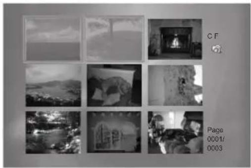
natural_image
Grid of nine grayscale outdoor scenes with no visible text, numbers, or symbolsIllustration when a CF card is being used
Rotation
When you press the Ok while you are viewing the slide show in PHOTO mode, the image is paused temporarily. Then press ▲▼while the image is paused, and you can rotate the image.
Note:
- Although the image has changed because it is rotated, it will not be saved to the media card.
VIDEO

Select
VIDEO

ess the Ok button
The right nine images appear.


To select an image that you like
Prestation O

The video show starts.
Notes:
• To stop the video show, press the Back button.
- The volume can not be changed when these nine images appear.
- In the playback of MPEG4 images, verification has been made for basic playback only.
- In thumbnail view, the time to display the images varies depending on the number of files recorded on the card.
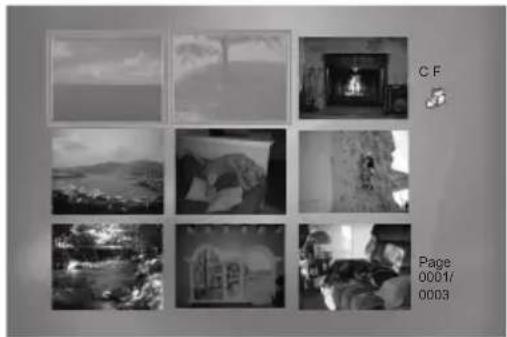
natural_image
Grid of nine grayscale photos showing outdoor scenes with hills and buildings, no visible text or symbolsIllustration when a CF card is being used
File playback note for PHOTO and VIDEO
- Some recorded files can result in errors or may not be played back correctly. Sometimes, JPEG, MPEG2, and MPEG4 files downloaded from the Internet or other sources cannot be played back correctly. Images also may not be played back correctly depending on the camera that was used for recording.
- Noise may appear when images change in the slideshow.
- The display order in the slideshow follows alphabetical order of the file names.
- If video, still images, and other files with different extensions are stored in the same folder, start of video playback may be choppy or other playback problems may occur. Storage of different fi le types in separate folders is recommended.
- When video or still images are recorded by Everio, only video recorded in a compact hard disk can be played back. Video recorded in the SD card cannot be played back.
- You may not be able to replay audio on some files created or edited with "CyberLink DVD Solution" software (provided with some JVC digital cameras). This will depend upon the way in which the files were created or edited and is not a malfunction of the TV.
FILE

Select
FILE

ess the Ok button
The following screen appears.
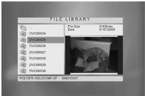
text_image
FILE LIBRARY ... DVC00024 DVC00025 DVC00026 DVC00027 DVC00028 DVC00029 DVC00030 File Size 91KBytes Date 01/01/2005 FOLDER 100.VCGR CF 0002/0007Illustration of CF file library
▲ ▼Everytime a file is selected in the left frame, the image will appear in the right frame.
Notes:
- To be released from the FILE, press the BACK button.
- The date displayed in the FILE view is the date the images were recorded. The date may not be displayed for some cameras.
- Only the first eight characters of the file name are displayed. Double-byte characters are not supported.
- The display order of thumbnails follows alphabetical order of the folder names and then alphabetical order of the file names in the folders.
Media Card Viewer
Operation Note
Operation of the CH+ and CH- keys is different for slideshows started from the PHOTO/VIDEO icon and for slideshows started from the FILE icon.
1) When you select VIDEO icon and play the video, press the following buttons:
CH+ : Fast-Forward
CH- : Rewinding
VOL+ : Up volume
VOL- : Down volume
OK : Pause or Play (Each pressing will switch back and forth)
2) When you select FILE icon and play the PHOTO or VIDEO:
While playing PHOTO – You cannot use CH+/CH- and VOL+/-
While playing VIDEO – You cannot use CH+/-. You can change volume by using VOL+/-.
Note: While using the card viewer, do not unplug the television from the AC outlet. It will cause the card to break.
Specifications
1) Supported card media
| Card Media | CompactFlash | CF type Microdrive Hard Disk | SD Memory Card | Memory Stick | xD-Picture Card |
| MPEG2-PS | √ | √ | |||
| MPEG4 | √ | √ | √ | √ | √ |
| JPEG | √ | √ | √ | √ | √ |
2) Supported fi le systems
3) Supported data management standards
(1) DCF 2.0 (still image)
(2) SD-Picture (still image)
(3) SD-Video Entertainment Video Profi le (video) compliant (Video: MPEG2-PS MP@ML, Audio: Dolby Digital)
(4) SD-Video Mobile Video Profi le (video) compliant
(Video: MPEG4 Simple profile/ Level 1 restricted to Level 3, Audio: G.726)
4) Supported image file standards and extensions
(1) Exif 2.21 (Extensions: JPG, jpg, JPEG, jpeg)
(2) JFIF (Extensions: JPG, jpg)
(3) SD-Video MPEG2-PS (Extensions: MOD, mod)
(4) SD-Video ASF MPEG4 (Extensions: ASF, asf)
5) Supported image size and rate
(1) Still images 160 × 120 to 2560 × 1920 pixels (The size is automatically adjusted when displayed.)
(2) Video 1) MPEG2-PS 720×480 pixels (525/60 systems)
$$ 3 5 2 \times 2 4 0 \quad \text { pixels } \tag {525/60} $$
2) MPEG4 352×288 pixels/30 frames
$$ 2 4 0 \times 1 7 6 \quad \text { pixels / 15 } \quad \text { frames } $$
$$ 1 6 0 \times 1 2 0 \quad \text { pixels / 5 } \quad \text { frames } $$
OSD Information
Weak Signal
This OSD warning appears when the digital channel that you have selected is too weak to receive or no signal is being detected for that channel.

text_image
Weak Signal 15No Program
If the TV channel you selected, or were watching is not receiving a signal, "NO PROGRAM" appears on the television screen. It appears when that channel is not receiving a signal and you have the Noise Muting function OFF and you have a single screen. It moves automatically every two seconds to prevent the screen from burn-in.
Note:
- Even if "NO PROGRAM" appears on the screen, your timer functions and auto shut off functions that you set, are still active.
Invalid Signal
If you are inputting a PC signal that is invalid, "Invalid Signal" will appear on the TV screen. It appears when the input is PC and it is a single screen.
Cable Card Information
Cable card offers information when a cable card is inserted into the CABLE CARD slot on the back of the TV.
Notes:
- Please contact your local cable company regarding detailed information.
Cable Card Connection
text_image
CABLE CARD CABLE CARD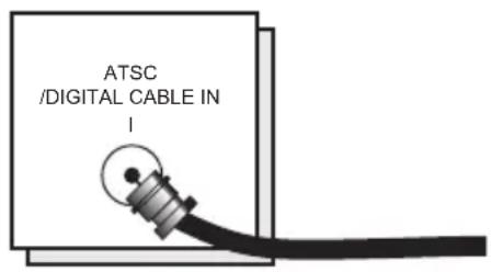
text_image
ATSC /DIGITAL CABLE IN !TV Rear Panel
Notes for inserting Cable Card:
- Firmware Upgrade of Cable Card can be executed. While executing the Firmware Upgrade, please do not turn off the TV, according to the message on the TV screen.
- When you are watching a program, and if a weather or government emergency occurs, the following may occur automatically regardless of what channel you were watching: the channel may change, the screen will disappear or important text will appear on the screen. The information is transmitted from EAS (Emergency Alert System). EAS information may also appear when you do not have a cable card inserted.
Troubleshooting
| PROBLEMS CHECK | |
| There is no power | • See if the power cord became unplugged.• Check for a blown fuse or circuit breaker or a power outage.• It is possible the fan is stuck or the inside temperature is rising abnormally.Consult your dealer. |
| The POWER LED and LAMP/PROGRAM LED are blinking alternately. | • It may be a malfunction that the fan is locked or the temperature has increased. |
| The POWER LED and LAMP/PROGRAM LED are blinking rapidly simultaneously. | • The lamp may not have been installed correctly, or it may be due to a malfunction.• The lamp door may not be closed correctly. |
| There is no picture or sound | • The antenna could be disconnected.• The input mode could be set improperly. See page 69.• The tuner (Auto Tuner Setup) could be set improperly. See page 40.• The TV station may be having difficulties. Check to see if other stations are working.• Use the HDMI cable with HDMI logo HDMI. See page 25. |
| Remote control is not operating properly or at all | • Check to see that the batteries are still working and properly installed.• Make sure the remote has a clear sight path to the TV.• Check that the TV/CATV switch is in the proper position.• You may be too far from the TV. You must be within 23 feet (7 meters). |
| You cannot select a certain channel | • Make sure the channels have been programmed. See "Channel Summary", page 41.• Check to see if the channel is locked. See "Channel Summary - Lock" page 42. |
| The power turns off by itself | • Make sure the set did not become unplugged.• Perhaps the On/Off Timer is set. See page 65.• Check to see if the Sleep Timer was set. See page 72. |
| It does not operate correctly | • This television is operated by a microprocessor. It is possible that external noise or interference is causing the problem. If the television does not function correctly, remove the electrical plug from the wall outlet and wait a while before inserting it into the wall outlet again and operating the television. |
| The clock is wrong | • The power was interrupted and the clock was not reset. See page 64. |
| The color quality is poor | • Tint and Color may be improperly adjusted. See page 60.• The Video Status mode may be turned to the wrong setting. See page 71. |
| There are lines across the picture | • There could be interference from another electrical appliance, such as a computer, another TV or VCR. Move any such appliances further away from the TV. |
| The picture is spotted | • There could be interference from a high-wattage appliance, like a hairdryer or vacuum, operating nearby. Move the antenna away from the appliance or change to a coaxial cable connection which is less prone to interference. |
| There are double pictures (ghosts) | • A building or passing airplane can reflect the original signal and produce a second, slightly delayed one. Adjust your antenna position. |
| Picture is snowy (image noise) | • Your antenna may be damaged, disconnected or turned. Check the antenna connection. If the antenna is damaged, replace it. |
| Screen is 80% black | • The Closed Caption Text mode is on. Turn it off in the Closed Caption Menu, page 50. |
| Stereo or bilingual programs can't be heard | • Make sure the MTS settings are correct. See page 72. |
| The LAMP/PROGRAM LED continues blinking | • It may be a malfunction of the internal electrical circuits. |
PROBLEMS CHECK
| There is no sound from the TV's speaker | ·The Center CH Input may be turned on. See page 59.·The TV Speaker option may be turned off. See page 57. |
| Static electricity | ·It is normal to feel static electricity if you brush or touch the screen. |
| You hear occasional crackling sounds | ·It is normal for the TV to make crackling sounds when first turned on or off. Unless the sound or picture become abnormal, this is fine. |
The following are not malfunctions.
- The television may make a creaking sound if the temperature of the room or the temperature inside the television changes. If there is no problem with the screen or sound, then there is no need to worry.
- The lamp may make a noise when it blows, but this is not dangerous.
- The lamp may make a noise when the power is turned on and a picture is displayed on the screen. This noise is caused when the mercury inside the lamp is heated, and is not a malfunction.
- The still parts of a picture may remain on the screen. This is a characteristic of HD-ILA elements and not a malfunction. The picture will disappear over time.
- The operation of this television is not guaranteed below 0^ C. If the power is turned on while the temperature is below 0^ C, the picture may be disturbed. Use the television when the temperature is 0^ C or higher.
- Although the HD-ILA element is manufactured with high-precision technology, please understand that some pixels may be lost or permanently displayed.
- There is a cooling fan built-in to the television. Please understand that this fan will make some noise when the television is on and while cooling.
- Although the picture may be temporarily disturbed and noise may be seen on the screen if the power is turned on immediately after it has been turned off. This is not a malfunction.
Changing the Lamp
WARNING!
It is very important that you NEVER TOUCH THE GLASS SURFACE OF THE NEW LAMP. Touching the glass surface will deposit oils from your hand onto the lamp surface. When the lamp heats up to its operating temperature, the oil will cause a difference in temperature on the lamp surface that will likely cause the lamp to break.
Replace the lamp with part number TS-CL110U only! The television is designed to work specifically with this lamp. Using a different lamp, or a third-party manufacturer's lamp could cause a malfunction and or damage to the television.
This television uses a 110-Watt high-pressure mercury lamp to project images onto the television screen. When the lamp nears the end of its operating life, you may notice the picture becoming dark. When the picture begins to darken, or the lamp burns out, it is time to replace the lamp. The following instructions will tell you how to safely replace the lamp.
WARNING!
Under operating conditions, THE LAMP WILL GET EXTREMELY HOT AND WILL CAUSE SEVERE BURNS IF TOUCHED.
Before attempting to replace the lamp, make sure the television has completely run through its cooling cycle. Turn the power off and wait until the LAMP/PROGRAM LED blinks very slowly and turns off completely. Unplug the TV. If you feel any warmth as you place your hand near the lamp, DO NOT TOUCH IT. Wait until the lamp has completely cooled before attempting to replace it. After turning the power off, wait at least 1 hour or more.
NEVER attempt to replace the lamp with the television plugged into a wall outlet. Attempting to replace the lamp with the TV plugged in could lead to a severe electrical shock.
Do not keep the TV on for more than 24 hours consecutively. There is the possibility of the life of the lamp being shortened.
The life of the lamp changes depending on the atmospheric temperature and altitude in which the TV is being used.
Please read these instructions fully before attempting to replace the lamp. If you feel unsure about replacing the lamp yourself, call a service technician.
Replacement Lamp Kit
Before replacing the lamp, you will need to purchase a replacement kit, part number TS-CL110U. To purchase this kit, consult your dealer or call 1-800-252-5722, or go to www.jvc.com.
The replacement kit will include the following:
1 High-Pressure Mercury Lamp 1 Instruction Manual
Because the lamp contains a small amount of mercury, it cannot be disposed of with normal trash.
Lamp Message
LAMP NEEDS TO BE REPLACED. REFER TO OWNER'S MANUAL FOR REPLACEMENT INSTRUCTIONS.
AFTER REPLACING THE LAMP, PLEASE RESET TIMER IN THE TV MENU.
PRESS OK, IF YOU DO NOT WANT TO SEE THIS MESSAGE AGAIN.
If this message appears when you turn the TV on, you need to replace the lamp.
Note:
- This message will appear every time you turn on the TV when the lamp needs to be replaced. Press the OK button to make the message disappear, or replace the lamp.
How to Replace the Lamp
Please read these instructions fully before attempting to replace the lamp. If you feel unsure about replacing the lamp yourself, call a service technician. Please observe all safety warnings.
1) Turn off the television.
Press the POWER button on the remote control or TV front panel. Wait until the picture has closed and the LAMP LED on the front panel has stopped blinking indicating the lamp cool down is complete.
Warning: The cool-down process cools the lamp from its operating temperature. This does not mean that the lamp will now be cool enough to handle safely. We strongly recommend you wait at least one hour before proceeding.
2) Unplug the television.
Disconnect the power cord from the AC outlet. Make sure that the LAMP LED light has stopped blinking before you unplug the set. Never attempt to replace the lamp with the television plugged in.
3) Remove the lamp cover.
The lamp is located behind the lamp cover below the left side of the television. To access the lamp you will need to remove the lamp cover. First, remove the screw located on the lamp cover using a Philips head type screwdriver (cross-head type). Once the screw has been removed, gently pull the knob towards you and the panel will come away from the television. Set it aside.
Note: Depending on which television you have, the lamp cover type shown to the right may be attached. If this is the case, you can loosen the screw located on the lamp cover by using your fingers, without the use of a Philips screwdriver (cross-head type). If the screw is difficult to loosen with your fingers, gently use a coin to loosen.
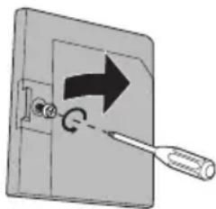
natural_image
Diagram of a mechanical switch with directional arrow and circular motion indicator (no text or symbols)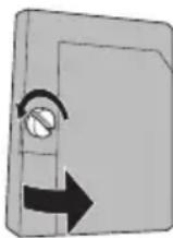
WARNING: DO NOT attempt to remove the assembly until the lamp has fully cooled. If you feel any heat near the lamp, STOP and wait until the lamp has FULLY COOLED.
NEVER attempt to remove the lamp with the television plugged into an outlet.
DO NOT DROP the used lamp. The inside of the lamp is under pressure. Dropping or other hard shock could cause the lamp to shatter.
ALWAYS recycle the used lamp. Because the lamp contains a small amount of mercury, it cannot be thrown away with regular trash. Follow the recycling instructions included with the Lamp Replacement Kit.
Appendix
4) Remove the lamp unit.
Using a Philips head type screwdriver (cross-head type), loosen the two screws fastening the lamp unit. When the screws have been loosened, remove the lamp by raising the handle and gently sliding the unit straight towards you. Place it carefully in the recycling packaging.
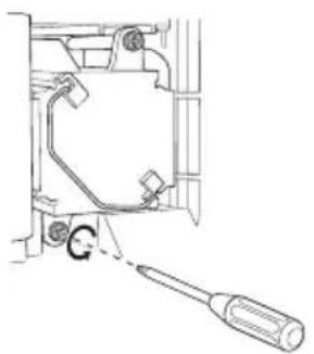
natural_image
Technical line drawing of a mechanical assembly with a screwdriver inserted (no text or symbols)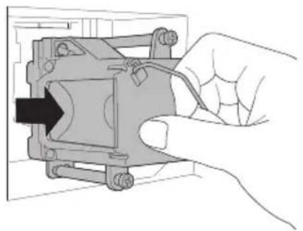
natural_image
Hand inserting a component into a device housing (no text or symbols visible)5) Install the new lamp unit.
Holding the handle attached to the new lamp unit, slide and push the new lamp straight into the television and back into the lamp housing area. Do not forget to re-tighten the two screws.
Note: If the lamp does not sit securely in the TV (flat in the lamp housing area), it won't turn on. Make sure the lamp sits securely and flat in the housing area.
WARNING!
Remember it is very important that YOU DO NOT TOUCH THE LAMP SURFACE. Please read the warnings on page 98 again.
Also, replace the lamp with part number TS-CL110U only! The television is designed to work specifically with this lamp. Lamps other than TS-CL110U may cause malfunctions and/or other damage to the television.

NOTICE (for USA)
This product has a High Intensity Discharge (HID) lamp that contains a small amount of mercury. It also contains lead in some components. Disposal of these materials may be regulated in your community due to environmental considerations. For disposal or recycling information, please contact your local authorities, or the Electronics Industries Alliance: http://www.eiae.org
To purchase a replacement lamp kit, please call 1-800-252-5722.
6) Re-install the lamp cover.
Insert the lamp cover in the right concave and close the lamp cover. Because the lamp cover has a role to help prevent the danger of an electrical shock, tighten the screw using your fingers.
Note:
• After installing the new lamp unit, do not forget to reset the lamp timer. See page 66.
Warning LED Messages
While the power is on, and there is a problem with the TV, the TV changes to warning mode and informs you of the problem using the LED as follows. Then, the power turns off automatically and performs the cooling for approximately 90 seconds.
The LAMP/PROGRAM LED blinks
Condition: It may be a malfunction of the internal electrical circuits.
To correct: Keep the TV off for a while and then turn the power on again. If the TV goes into warning mode, unplug the TV after the cooling has completed and consult your dealer.
The POWER LED and LAMP/PROGRAM LED blink alternately
Condition: The inside temperature rises abnormally or the fan may be blocked.
To correct: Keep the TV off for a while and then turn the power on again. If the TV goes into warning mode, unplug the TV after the cool down as completed and consult your dealer.
The POWER LED and LAMP/PROGRAM LED blink rapidly simultaneously
Condition: The lamp unit has been installed on a slant and is not flat, or it is not fully inserted into the lamp housing. Or it may be a lamp malfunction.
To correct: • If this condition occurs soon after replacing the lamp: Reinstall the new lamp unit. Repeat the lamp installation steps, taking care to observe all warnings. Make sure the lamp sits FLAT inside the unit when you reinstall it. • If this condition occurs except for replacing the lamp: Keep the TV off for a while and then turn the power on again. If the TV goes into warning mode, unplug the TV after the cool down as completed and consult your dealer.
TO OUR VALUED CUSTOMER
THANK YOU FOR PURCHASING THIS JVC PRODUCT.
WE WANT TO HELP YOU ACHIEVE A PERFECT EXPERIENCE.
NEED HELP ON HOW TO HOOK UP? NEED ASSISTANCE ON HOW TO OPERATE? NEED TO LOCATE A JVC SERVICE CENTER? LIKE TO PURCHASE ACCESSORIES?
JVC® IS HERE TO HELP!
TOLL FREE: 1(800)252-5722 http://pro.jvc.com/
Remember to retain your Bill of Sale for Warranty Service.
Do not attempt to service the product yourself
Caution
To prevent electrical shock, do not open the cabinet.
There are no user serviceable parts inside.
Please refer to qualified service personnel for repairs.
| Model | HD-P70R1U HD-P61R1U | |
| HD-ILA Device Projection Type | ||
| Reception Format | NTSC, BTSC System (Multi-Channel Sound)ATSC Terrestrial, Digital Cable | |
| Reception Range | VHF 2 to 13, UHF 14 to 69 at ATSC,CATV 135 Sub, Mid, Super, Hyper and Ultra bands at Digital Cable | |
| VHF 2 to 13, UHF 14 to 69 CATV 125 Sub, Mid, Super, Hyperand Ultra bands (191 channel frequency synthesizer system) at Analog• Reception of channel A-5 ("95" of the TV set's on-screen cable channelnumbers) is not recommended for your TV set. | ||
| Power Source | AC 120V, 60 Hz | |
| Power Consumption | 215W | 220W |
| Projection Source | 110W High-Pressure Mercury Lamp | |
| Screen Size | 61 inch / 155 cmmeasured diagonally,16:9 ratio | 70 inch / 178 cmmeasured diagonally,16:9 ratio |
| Speakers 10 cm round X 2 | ||
| Audio Output Full Range - 10W + 10W | ||
| Antenna Terminal(VHF/UHF,ATSC/DIGITALCABLE IN) | 75 ohms (VHF/UHF)(F-type connector) | |
| External Input Jacks | Video: 1 Vp-p, 75 ohmsAudio: 500 mVrms (-4dBs) high impedance | |
| Component InputJack | Y: 1Vp-p positive, 75 ohms (negative sync provided)Pb/Pr: 0.7 Vp-p 75 ohms | |
| S-Video Input Jacks | Y: 1Vp-p positive, 75 ohms (negative sync provided)C: 0.286 Vp-p (burst signal), 75 ohms | |
| Monitor/RecordingOutput | Video: 1Vp-p, 75ohmsY: 1Vp-p positive, 75 ohms (negative sync provided)C: 0.286 Vp-p (burst signal), 75 ohmsAudio: 250mVrms (-10dBs)Fs-18dB Low Impedance | |
| Audio Output Jacks(VARI/FIX) | VARI: More than 0 to 1000mVrms (+2.2dBs)FIX : 500mVrms (-4dBs) Low impedance (1000 Hz when modulated 100%) | |
| Optical OutputDigital Audio | Digital Out (optical) x 1 | |
| i.LINK In/Out Jack | TS IN/OUT (4-pin, S400) x 2IEEE1394 compliant DTCP digital copy protection compatible | |
| AV CompuLink IIIJack | 3.5 mm mini jack X 1 | |
| PC Input Jack | Analog RGB D-SUB (15 pin) x 1, RS-232C (9 pin) x 1• PC signal is available. Refer to page 29 for details on the signals whichcan be input. | |
| Digital-In | HDMI jack x 2Note: The Digital-In terminal is not compatible with picture signals of apersonal computer | |
| Readable Cards | SD Card, MMC, CompactFlash Card,Removable microdrive Hard Disk for JVCdigital media camera "Everio" (a type of CF card),Memory Stick, xD-Picture Card | |
| Dimensions (inch)W X H X D (cm) | 57 3/8 x 41 1/8 x 18 3/8145.6 x 104.3 x 46.7 | 64 1/8 x 46 x 20 1/2162.6 x 116.8 x 51.9 |
| Weight (lbs / kg) | 104 / 47 | 159 / 72 |
| Accessories | Illuminated remote control unit x 1 / AA batteries X 2Two-way Splitter x 1 / RF Cable x 2 | |
Specifications subject to change without notice.
- The open source software is embedded in this product. For more information, please go to: http://software.jvc.com/opensource/lnx/DP/04_AtscCC/download.html