Elite-202 - Hi-Fi System JENSEN - Free user manual and instructions
Find the device manual for free Elite-202 JENSEN in PDF.

User questions about Elite-202 JENSEN
0 question about this device. Answer the ones you know or ask your own.
Ask a new question about this device
Download the instructions for your Hi-Fi System in PDF format for free! Find your manual Elite-202 - JENSEN and take your electronic device back in hand. On this page are published all the documents necessary for the use of your device. Elite-202 by JENSEN.
USER MANUAL Elite-202 JENSEN
natural_image
Technical line drawing of a square mechanical component with mounting holes and central bore (no text or symbols)Elite-101
natural_image
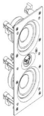
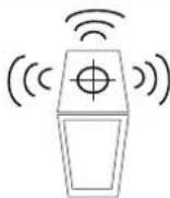
Technical line drawing of a multi-tiered speaker or amplifier housing with mounting brackets (no text or symbols)Elite-202
natural_image
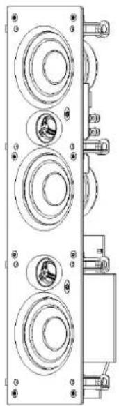
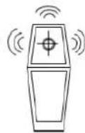
Technical line drawing of a multi-tiered electronic device with circular components and mounting holes (no text or symbols)Elite-303

natural_image
Line drawing of a rectangular speaker or audio device with a circular vent and four legs (no text or symbols)Elite-606
See separate manual
Congratulaons for buying the best In-Wall Speakers on the planet!
Please read this manual carefully understanding that advanced planning is essenal.
Check for damage: We know you will be eager to install your new Speakers, however, please rstly inspect your units for any damage. If you nd a problem please contact us immediately at info@bdimports.com.au
Supplied
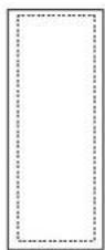
Template

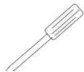
Wall cut tool
Not supplied
Philips screw driver
Stud Finder
Wall Cavity
Depth required:
Elite-101 85mm
Elite-202 62mm
Elite-303 75mm
Break in Period:
Premium grade parts and materials are used in these Elite-101/202/303 products so maximum performance can be obtained in damp and dusty environments such as wall and ceiling cavity. Break In period is appx 10-20 playing hours aer which me Bass will improve. There is no need to limit playback volume at all during this me.
Step 1: Advanced Planning
Decide the placement for your speakers. Advance planning in regards to the placement of your speakers is crical. It is imperave that the wall or ceiling cavity be free from debris, moisture,
insulaon, and any materials that are easily combustible. The moung locaon must also be void of wall studs or bracing in the locaon for the cutout. Adequate Wall Cavity depth (see above) to allow speakers to t ush to the wall or ceiling surface is important. If you are unsure of the contents of the wall in which you wish to mount the speakers, Electronic Stud Finders work very well (see FIG 1), otherwise a professional installer can assist here.
FIG 1.
Stud Finder
Step 2: Fing Glass Grills
Fit Elite-101 grills squarely and be certain ALL 4 magnets grab and not just 2 or 3. For Elite-202/303, align all 8 pins then gently press Glass panel into rubber bushes. When removing, pull a lile from top, then from boom to remove evenly.
Step 3: Template:
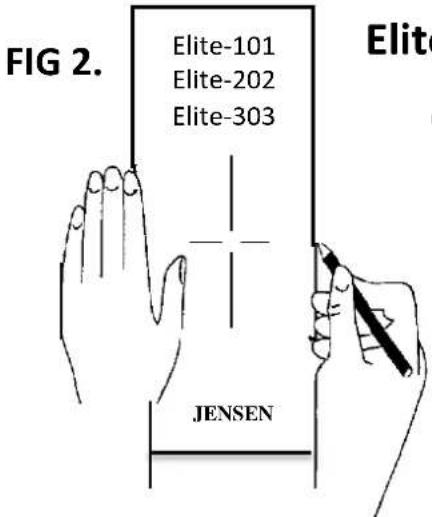
Use the supplied template and mark the cut-out on the wall or ceiling. To mark, simply trace with a pencil, along perforated line (see FIG 2). Ensure your markings are level.
Step 4: Cung the Wall / Ceiling
Using the appropriate wall-cung tool, blade or Stanley knife, accurately cut the hole in the wall material, based on the correct cut-out dimension (see FIG 3).
Template
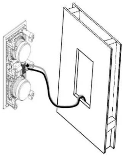
Step 5: Installing Speaker Leads
For Elite-101 and 202, from your Receiver run one speaker cable thru the wall/ceiling to each Le and Right speaker (see FIG 4). For Elite-303, run TWO speaker cables thru the wall/ceiling to each Elite-303 as this model has inbuilt Centre/Le and Centre/Right speakers as well as Le and Right. (See FIG 5 and FIG 7). In both cases, leave enough slack in wire so that it can hang out of hole.
Step 6: Red-to-Red & Black to Black
Connect the speaker wire from the posive (RED+) terminal on the receiver to the posive (RED+) terminal on the speaker. Connect the negave (BLACK-) the same way to the negaves. Note: If you inadvertently reverse one of the connecons (i.e. RED to BLACK) you will noce a severe lack of Bass from your system. This is called wiring your system "Out of Phase". If this occurs, check the wiring and reconnect as necessary.
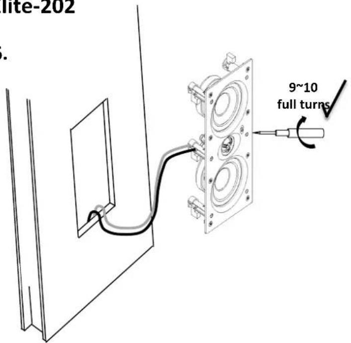
Step 7: Mounng Speakers Insert the enre speaker into the hole. Move Speaker wire away from back of cone to avoid a possible rale. Using a Phillips head screwdriver, ghten the screws aached to the dog clamps unl you feel Dog Clamps take grip (9\~10 FULL TURNS). At this point you can see the gap between Speaker Frame and wall/ceiling close fully. Then, NIP THESE UP - DO NOT OVERTIGHTEN. See FIG 6. Note: If you are unable to install these speakers yourself, please contact an authorized electrician or installaon contractor.

Boost switches.
Sound Sengs
Boost switch. Adjust Elite-202 / 303 Treble switches to suit your sound preference.
If using a Subwoofer set to (+) to fully maximize performance. Note: Elite-101 has no switches but is factory preset to Max Boost (+).
Eyeball Tweeters. You can adjust the angle of the Tweeter slightly in order to compensate for poor moung locaons. Do this by adjusting Tweeter casing. DO NOT touch the Tweeter in any way as permanent damage may occur.

Eyeball Tweeters
Matching Subwoofer : Elite-606:
140 Was RMS, Heavy-Duty "monster" driver with 40oz magnet and 2"Voice Coil is perfectly matched to ALL JENSEN Speakers. Available in stunning Hi-Gloss White or Black. See separate Info Manual.
Elite 606
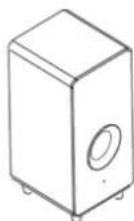
FIG 3.
text_image
FIG 2. Elite-101 Elite-202 Elite-303 JENSENElite-101, 202 & 303
Once nal moung posions are determined, use pencil and template (supplied) to mark the wall and cut-out.

text_image
FIGTIPS:
√ 1. Use Laser level or Spirit level to ensure template is perfectly level.
√ 2. Use a Stud Finder to Pre-plan your locaons.
√ 3. Both ends of Speaker Leads must be Pos (+) to Pos (+) & Neg (-) to Neg (-)
√ 4. Do not use Baery Drill.
Elite-101 & 202
Run 1 Speaker lead to each Le & Right Speaker.
(FIG 4)
FIG 4.
natural_image
Technical line drawing of a device with an attached cable, showing internal components and a separate panel (no text or symbols)Elite -303
FIG 5.

text_image
Run 2 Speaker leads to each Le & Right Speaker. (see FIG 7) To amp Centre To amp L/RElite-202
FIG 6.
text_image
Lite-202 9~10 full turnsTIPS: 9\~10 Full Turns.
With a screw cung a new plasc thread, the rst few turns may appear s. It will become easier. The trick is to gently close the gap between Speaker panel and wall, then
NIP THESE SCREWS UP - DO NOT OVERTIGHTEN AND DO NOT USE A BATTERY DRILL.

Elite-303 wiring diagram
Front Channels. From Receiver, run 2 Speaker Leads (one for L/R and other for Centre) to each LEFT and RIGHT Speaker (FIG 7). At receiver end, take the two Centre Speaker Leads and TWIST both posives together and connect to positive Centre terminal on Receiver. Dio with Negaves to negative terminal. It is imperative to keep all positives together and all negatives together.
Placement: Only rule is LEFT and RIGHT Speakers to be same distance from TV screen. We suggest each to be 200mm \~ 350mm from Screen.
FIG 7.
Receiver / Amplifier
Front Channels

flowchart
graph TD
    A["Speaker Leads 1 & 2"] --> B["Le"]
    B --> C["Centre"]
    C --> D["Right"]
    D --> E["Speaker Leads 3 & 4"]
    F["Le 6 Ohms"] --> G["Screen"]
    H["Centre/L 12 Ohms mono"] --> G
    I["Right 6 Ohms"] --> G
    J["Centre/R 12 Ohms mono"] --> G
    G --> K["Centre"]
    style G fill:#f9f,stroke:#333
    style H fill:#ccf,stroke:#333
    style I fill:#cfc,stroke:#333
    style J fill:#fcc,stroke:#333
| Elite-101 | Elite-202 | Elite-303 | Elite-606 | |
| Shape | Square | Rectangular | Rectangular | Gloss Black / White |
| Suited for | Wall | Wall | Wall | Floor Subwoofer |
| Descripon | Glass front6.5”2 Way | Glass frontTwin 4.5”2 Way | Glass front Twin 4.5”2 Way + inbuilt Twin4.5” 2 Way CentreSpeaker | Hi Gloss enclosure with Down-ring 8”“Monster” driver with 40oz magnet & 2”V/coil |
| Tweeter size mm / inches | 28mmPure Silk Dome | 28mmPure Silk Dome | Twin 28mmPure Silk Domes | n/a |
| Power Handling | 110 W RMS | 140 W RMS | 140 WRMS + 140WRMS | 140 Wa RMS Output |
| Nom. Impedance | 6 Ohms | 6 Ohms | 6 Ohms | n/a |
| Sensitivity | 91db | 90db | 90db | n/a |
| Frequency Resp. | 42Hz-21kHz | 40Hz-21kHz | 40Hz-21kHz | 35Hz-200Hz |
| Min. Mounng Depth mm | 85mm | 62mm | 75mm | n/a |
| Tweeter Boost switch | NO | YES | YES | n/a |
| Eyeball tweeter | YES | YES | YES | n/a |
| Paintable Faces & Grills | NO | NO | NO | n/a |
| Tweeter Protecon | YES | YES | YES | n/a |
| Magnec Shielding | NO | NO | NO | NO |
| Colours | Black / White | Black / White | Black / White | Hi Gloss Black or White |
| Outer Dimensions: mm | 240 x 240 | 570 x 163 | 650 x 163 | 460(H)x 277(W)x 313(D) |
| Cut-out Dimensions: mm | 226 x 226 | 325.5 x 137.5 | 568.5 x 137.5 | n/a |
| Warranty | 5 Yearsunconditional | 5 Yearsunconditional | 5 Yearsunconditional | 5 Years (1 year on amplifier module) |