
ODAC0708B - Mounting bracket Chief - Free user manual and instructions
Find the device manual for free ODAC0708B Chief in PDF.

| Product Type | Outdoor Floor/Ceiling Mounting Column |
| Brand | Chief |
| Model | ODAC0708B |
| Category | Mounting Bracket |
| Weight Capacity | 300 lbs (136 kg) |
| Maximum Moment | 2000 ft-lbs |
| Moment Length Range | 81 - 96 inches (min - max) |
| Material | Steel / Aluminum (estimated) |
| Finish | Powder coated (estimated) |
| Outdoor Use | Yes |
| Compatible Plates | ODA330 Floor/Ceiling Plate (not included) |
| Compatible Mounts | UL Listed flat panel mounts: OLCM1U, OXCM1U, OLCM2X1U, OLCB1U, OXCB1U, OLCB2X1U |
| Installation Requirement | Two people or mechanical lifting device |
| Annual Inspection | Required; also after major weather events |
| Safety Factor | Supporting structure must hold 5x total equipment weight |
| Intended Use | Outdoor flat panel display mounting |
| Warranty | Not specified in manual |
Frequently Asked Questions - ODAC0708B Chief
User questions about ODAC0708B Chief
0 question about this device. Answer the ones you know or ask your own.
Ask a new question about this device
Download the instructions for your Mounting bracket in PDF format for free! Find your manual ODAC0708B - Chief and take your electronic device back in hand. On this page are published all the documents necessary for the use of your device. ODAC0708B by Chief.
USER MANUAL ODAC0708B Chief
INSTALLATION INSTRUCTIONS

natural_image
Technical line drawing of a mechanical assembly with a bracket and mounting base (no text or symbols)
natural_image
Technical line drawing of a mechanical assembly with a vertical rod and mounting bracket (no text or symbols)Outdoor Floor/Ceiling Pipe
DISCLAIMER
Milestone AV Technologies and its affiliated corporations and subsidiaries (collectively "Milestone"), intend to make this manual accurate and complete. However, Milestone makes no claim that the information contained herein covers all details, conditions or variations, nor does it provide for every possible contingency in connection with the installation or use of this product. The information contained in this document is subject to change without notice or obligation of any kind. Milestone makes no representation of warranty, expressed or implied, regarding the information contained herein. Milestone assumes no responsibility for accuracy, completeness or sufficiency of the information contained in this document.
Chief® is a registered trademark of Milestone AV Technologies. All rights reserved.
DEFINITIONS
MOUNTING SYSTEM: A MOUNTING SYSTEM is the primary Chief product to which an accessory and/or component is attached.
ACCESSORY: AN ACCESSORY is the secondary Chief product which is attached to a primary Chief product, and may have a component attached or setting on it.
COMPONENT: A COMPONENT is an audiovisual item designed to be attached or resting on an accessory or mounting system such as a video camera, CPU, screen, display, projector, etc.
MOMENT: A MOMENT is a product of force and distance. It is calculated by multiplying the force applied by install drop length. See Dimensions drawings for further details.

WARNING: A WARNING alerts you to the possibility of serious injury or death if you do not follow the instructions.

CAUTION: A CAUTION alerts you to the possibility of damage or destruction of equipment if you do not follow the corresponding instructions.

IMPORTANT SAFETY INSTRUCTIONS

WARNING: Failure to read, thoroughly understand, and follow all instructions can result in serious personal injury, damage to equipment, or voiding of factory warranty! It is the installer's responsibility to make sure all accessories are properly assembled and installed using the instructions provided.

WARNING: Failure to provide adequate structural strength for this accessory can result in serious personal injury or damage to equipment! It is the installer's responsibility to make sure the structure to which this accessory is attached can support five times the combined weight of all equipment. Reinforce the structure as required before installing the accessory.

WARNING: Exceeding the weight capacity can result in serious personal injury or damage to equipment! It is the installer's responsibility to make sure the combined weight of all components attached to mounting system cannot exceed 300 lbs (136 kg).
NOTE: "Moment" ratings have NOT been evaluated by UL.

WARNING: Exceeding the maximum moment can result in serious personal injury or damage to equipment! It is the installer's responsibility to make sure the mounting system does not exceed a moment of 2000 ft-lbs. See table below for specific column specifications.
| COLUMN MODEL | Weight capacity | Moment Length (IN) (ML) | Max Design Moment (FT-LBS) (MDM) |
| ODAC0203B | 300 lbs (136 kg) 23 | min - 36 max 2000 | |
| ODAC0304B | 300 lbs (136 kg) 33 | min - 48 max 2000 | |
| ODAC0405B | 300 lbs (136 kg) 45 | min - 60 max 2000 | |
| ODAC0506B | 300 lbs (136 kg) 57 | min - 72 max 2000 | |
| ODAC0708B | 300 lbs (136 kg) 81 | min - 96 max 2000 |

WARNING: The weight capacity of the ODA mounting systems may be LIMITED to the lowest weight capacity of any component located between the ODA330 ceiling plate and the flat panel display(s).

WARNING: Use this mounting system only for its intended use as described in these instructions. Do not use attachments not recommended by the manufacturer.

WARNING: Never operate this mounting system if it is damaged. Return the mounting system to a service center for examination and repair.

WARNING: Use this mounting system with other outdoor products only.

WARNING: Always use two people or a mechanical lifting device to safely lift and position equipment.

WARNING: Due to exposure to outdoor elements such as strong wind gusts, heavy snow, hail, rain, etc., the mounting system and its supporting structure must be inspected at least once per year and immediately following any major weather event. If evidence of excessive wear, deterioration or any other unsafe condition is observed this product must be taken out of service immediately!
NOTE: The ODAC Series columns are intended to be used with UL listed flat panel floor/ceiling mounts (not included): OLCM1U, OXCM1U, OLCM2X1U, OLCB1U, OXCB1U, OLCB2X1U and UL Listed ODA Floor/Ceiling Plate ODA330 (not included).
--SAVE THESE INSTRUCTIONS--
DIMENSIONS
![ODAC3306 WEIGHT CAPACITY: 400 LBS/181.4 KG 12.00 [304.8] 8.00 [203.2] 4.00 [101.6] MOMENT LENGTH (ML) MAX FORCE = MDM / ML × 12 MODEL NUMBER APPROXIMATE WEIGHT [LBS] WEIGHT CAPACITY [LBS/KG] ACTUAL LENGTH (IN) MOMENT LENGTH (IN) (ML)** MAX DESIGN MOMENT [FT-LBS] (MDM)* COMPATIBLE WITH ODAC0203B 9 300/136 29.75 23 (MIN) - 36 (MAX) 2.000 CEILING ODAC0304B 12 300/136 41.75 33 (MIN) - 48 (MAX) 2.000 CEILING ODAC0405B 16 300/136 53.75 45 (MIN) - 60 (MAX) 2.000 CEILING ODAC0506B 19 300/136 65.75 57 (MIN) - 72 (MAX) 2.000 CEILING & PEDESTAL ODAC070BB 26 300/136 88.25 81 (MIN) - 96 (MAX) 2.000 PEDESTAL * SEE INSTRUCTION MANUAL ** ONE INCH INCREMENTS MAX FORCE → OLCM1U, OXCM1U, OLCM2X1U, OXCB1U WEIGHT CAPACITY: 250 LBS/113.4 KG PER DISPLAY OLCB1U, OLCB2X1U WEIGHT CAPACITY: 125 LBS/56.7 KG PER DISPLAY Ø2.875 [73.0] Ø0.872 [22.1] CONDUIT CLEARANCE CROSS BOLTS](/content/2026/06/1196255/images/727926e17f882734c2c4d290c0b6e0ea21765dbd9c316838c88f16f140adc39f.jpg)
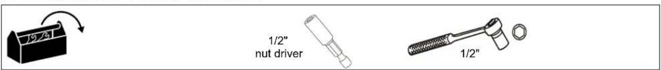
TOOLS REQUIRED FOR INSTALLATION
PARTS
![A (1) [ODA Series pipe]](/content/2026/06/1196255/images/250b45245c4dcc36068644cf60bb3e02cbb4c2ca770e1a2693a82fc779a644f3.jpg)
INSTALLATION
IMPORTANT ! : The following procedure assumes that the UL Listed ODA330 assembly (not included) has been properly installed following instructions provided with ODA330 assembly.
- OPTIONAL: Route cables/conduits through extension column (A).
- Insert column (A) in to ODA330 floor/ceiling plate (not included) until holes align for installation. (See Figure 1)

Figure 1
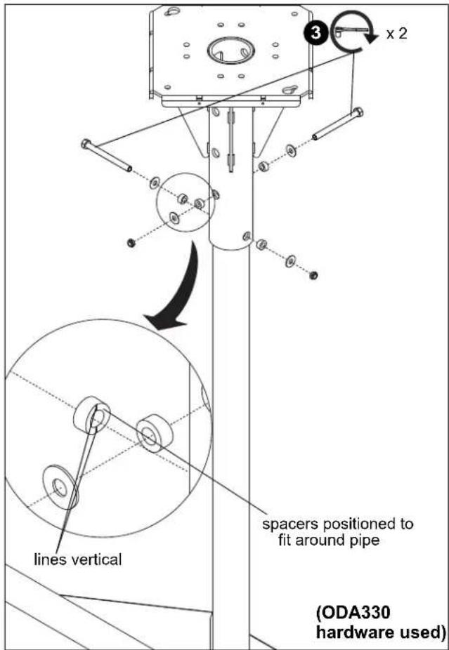
- Attach pipe (A) to ODA330 using hardware provided with ODA330 plate. (See Figure)
IMPORTANT ! : Make sure spacers are properly oriented to fit around pipe with the lines vertical.

WARNING: Exceeding the weight capacity can result in serious personal injury or damage to equipment! It is the installer's responsibility to make sure the combined weight of all components attached to mounting system cannot exceed 300 lbs (136 kg).
- Install outdoor ceiling mount and display to pipe (A) following installation instructions included with mount.

CHIEF®
Our Mounts. Your Vision.
Chief, a products division of Milestone AV Technologies
8800-003019 Rev00
©2018 Milestone AV Technologies
www.milestone.com
07/18
USA/International A 6436 City West Parkway, Eden Prairie, MN 55344
P 800.582.6480 / 952.225.6000
F 877.894.6918 / 952.894.6918
Europe A Franklinstraat 14, 6003 DK Weert, Netherlands
P +31 (0) 495 580 852
F +31 (0) 495 580 845
Asia Pacific A Office No. 918 on 9/F, Shatin Galleria
18-24 Shan Mei Street
Fotan, Shatin, Hong Kong
P 852 2145 4099
F 852 2145 4477


Brand : Chief
Model : ODAC0708B
Category : Mounting bracket