Matrix IMA-120 - Interactive whiteboard TeachLogic - Free user manual and instructions
Find the device manual for free Matrix IMA-120 TeachLogic in PDF.

User questions about Matrix IMA-120 TeachLogic
0 question about this device. Answer the ones you know or ask your own.
Ask a new question about this device
Download the instructions for your Interactive whiteboard in PDF format for free! Find your manual Matrix IMA-120 - TeachLogic and take your electronic device back in hand. On this page are published all the documents necessary for the use of your device. Matrix IMA-120 by TeachLogic.
USER MANUAL Matrix IMA-120 TeachLogic
Infrared Microphone Receiver
Date of Purchase: ____
Model Number: ____
Serial Number:
Notes:
THANK YOU
Congratulations on the purchase of your new TeachLogic system. You can be assured that this fulfills all specifications and was produced to very high quality control standards. TeachLogic incorporates the latest state of the art technology, employs the most advanced manufacturing methodology and uses only premium quality components to assure many years of reliable performance. We appreciate your confidence by your selection of our product. It is TeachLogic's intent to uphold that confidence by providing factory assistance and dealer support.
We hope you will take the time to review this manual to familiarize yourself with the product operation and features. This manual will help you learn to use and gain the maximum benefit of the system.
TeachLogic LLC
Longmont, Colorado, USA
teachlogic.com
contact
If you should encounter some unresolved issue, please contact TeachLogic customer service department for further assistance.
1-760-631-7800
support@teachlogic.com
www.teachlogic.com
safety instructions

CAUTION

RISK OF ELECTRIC SHOCK: DO NOT OPEN
Caution: To reduce the risk of electric shock DO NOT remove cover or back. No user serviceable parts inside Refer servicing to qualified personnel
certifications


TeachLogic systems are manufactured using lead-free processes and are free of materials harmful to the environment. They conform to the most stringent new European guidelines for consumer products (RoHS).
caution
Recycle—Do not dispose rechargeable batteries in trash. Actually it is unlawful to do so in CA, NY & ME.
Contact: Earth911.com 1-800-CLEANUP
Save our resources and don't contaminate. Go Green
Read Instructions
All safety and operation instructions should be read before operating this TeachLogic product.
Retain Instructions
Safety and operating instructions should be kept for future reference.
Water & Moisture
This product should not be operated near water.
Heat Environment
Do not subject this product to excessive heat conditions.
Power Source
This product must be connected to an AC power source per the voltage input specified and marked on the power supply.
Power Cord Caution
Power cable should be routed clear of foot traffic and supported clear of kinking or abrasion.
Object Protection
Locate the operating unit so it will not be subjected to falling objects or water entry.
Internal Service
User should not attempt to service this product. All internal service must be accomplished by a qualified technician.
Electric Shock
Do not adapt or modify the AC power plug thus lifting the earth ground connection.
table of contents
About Infrared 6
System Overview 7
Wiring Diagram 8
Infrared Microphones 9-10
Components: Drop-in Charger BRC-60/Ceiling Sensor ICS-55 11
Installation of Ceiling Sensor 12
Installation of Ceiling Speakers 13-14
Installation of Wall Mount Speakers 15
Final Connection of Speakers 16
Page Mute/Pass Through 17
CPS-120/CPR-125 Remote Control Panel 18-19
RS-232 Features / RS-232 Codes 20
Bluetooth 21
Security Alert Feature 22
System Operation 23
Troubleshooting 24
Five Year Limited Warranty 25
a brief word about infrared
Infrared is a light ray that is below the visible spectrum, just like sound extends beyond your hearing ability. An example of infrared transmission is the remote control for your TV set. When a button is pressed, a beam of infrared light is emitted by a Light Emitting Diode (LED) from the remote control. It is detected by a receiving diode in your TV set.
When you press a certain command on your control, the internal electronics cause the infrared light to flicker in a programmed sequential pattern (called modulating the light beam). The modulated infrared beam is detected by the receiving diode and is electronically decoded. The decoded signal activates the circuitry to perform the command function on your TV set.
So how does this apply to the infrared communication system you are about to start using? The microphone/transmitter has several Light Emitting Diodes (LED) that emit infrared light beams to the sensor located in the corner of the room.
When you talk into the microphone, the microphone element modulates the light beam, causing it to flicker in sync with your speech. The sensor detects the sequential signal and the electronic circuitry in the amplifier converts that sequential signal into a line level analog audio signal. Now that audio signal can be fed into an amplifier. The amplifier magnifies the electronic signal and sends it to the speakers. This causes the speaker cone to move in sync with your voice. The speaker replicates your voice and disperses your voice evenly throughout the room.
IR transmission
The IR transmitter transmits directly to the sensor. However; due to the strength of the IR transmitter, the infrared signal will bounce off the walls, ceiling and floor for reception thus providing continuous connectivity throughout the room. Benefit: total freedom of movement within the room with no restriction of orientation.
"What's said in the room, stays in the room".
Infrared will not penetrate a solid surface thus preventing any transmission from going out of the room.
system overview
The Matrix is an amplifier, audio mixer, and infrared wireless microphone receiver in one. It is the hub of the classroom audio system as various media inputs can be connected to it, so that all classroom audio can be amplified and distributed clearly through the speakers. The addition of microphones provides voice reinforcement for the teacher and students alike.
The Matrix system is comprised of a microphone / transmitter, either the Sapphire (IRT-60), or Handheld (IRH-35) for voice transmission to a ceiling sensor (ICS-55) that sends the signal to the receiver / amplifier (IMA-120). The receiver/amplifier processes the signal and produces an analog signal of your voice for output to the sound field speaker system.


text_image
12 13 14 15 16 17 18 19 20wiring diagram

flowchart
graph TD
    A["CEILING/WALL MOUNT SPEAKERS"] --> B["THIRD PARTY INTERCOM/PAGING SPEAKER"]
    B --> C["3RD PARTY INTERCOM/PAGING SYSTEM WALL PANEL"]
    C --> D["Emergency"]
    C --> E["Normal"]
    C --> F["Wall mounted call button"]
    D --> G["Output to front office intercom panel via existing intercom cabling"]
    E --> G
    F --> G
    G --> H["CPS-120/CPR-125 REMOTE CONTROL PANEL"]
    H --> I["CEILING SENSOR(S)"]
    I --> J["Refrigerator with wireless signals"]
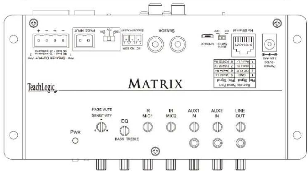
text_image
Any Breaker Output Any 90 kHz = 15 megahertz 2 60 kHz = 35 megahertz MAPS INPUT PAGE INPUT Signal Alert NO ON OOM Sensor ON OFF RS24 Switch Unknown No Endline 8854321 4 MHz 4.446 L - 8 Audi6 L - 7 M5227 T6 3.000 Hz - 7 Audi6 L - 6 Audi6 L + 5 2.00 GHz - 6 CND - 5 Audi6 L + 4 PWR PAGE MUTE SENSITIVITY EQ BASS TREBLE IR MIC1 IR MIC2 AUX1 IN AUX2 IN LINE OUT Power 1.25A MAX 1.00 DC 4.00 GHz 4.00 GHz - 1.00 GHz - 15 megahertz - 80 kHz - 15 megahertz - 60 kHz - 35 megahertz - 60 kHz - 35 megahertz - TeachLogic MATRIX
flowchart
graph TD
    A["UP TO 2 MEDIA DEVICES"] --> B["Lesson Capture Recorder"]
    A --> C["ASSISTIVE LISTEN DEVICE (3.5 mV) analog output"]
    D["AC/DA"] --> A
    E["Smartphone"] --> A
    F["Laptop"] --> A
    G["Laptop"] --> A
    H["Laptop"] --> A
    I["Audio Device"] --> A
infrared microphones
The infrared microphone/transmitter is comprised of a microphone input, signal processing circuits and several emitting diodes that transmit the vocal signal to the sensor.
The microphone/transmitter can be the Sapphire or Handheld. The rechargeable batteries will provide 6–8 hours of service per charge. Place the microphone/transmitter in the charger for overnight charge and it will be ready for another day's use.
The drop-in battery chargers are specifically designed to recharge lithium & NiMH batteries at an optimum rate for Matrixum operating capacity and extended service life. Charger will automatically start charging the batteries upon insertion and will shift to a maintenance charge when batteries are fully charged.
features
- Elegant design
- Only 1.4 oz. including battery
- Long life Lithium Ion battery
- Rechargeable via USB cable
- Battery level indicator – Back light under power switch
- Momentary mute button, backlight blinks in mute mode
- Push "on/off" power
- Channel "A" or "B" selectable
- Three level microphone volume switch
• 3 voice sensitivity settings (Normal, -3dB, -6dB) - Auxiliary input (3.5mm) for headset or music device
- Wear with a lanyard or slide directly on neckline collar

natural_image
Black-and-white photo of a smiling woman wearing a necklace (no visible text or symbols)
natural_image
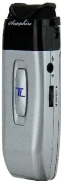
White handheld device labeled 'Tol' with black top and white body, no visible text or symbols beyond branding(IRT-60) sapphire transmitter
The Sapphire's vocal clarity is unsurpassed. Its high level output is achieved by the unidirectional (Cardioid) microphone and a unique free air suspension system. With a built-in breath filter, the Sapphire can function as a pass around hand mic.
The strategic alignment of the emitting diodes assures reliable connectivity throughout the room without static or drop out.
With a tap on the power button, the microphone is muted for private conversation—tap again to restore to normal operation. The auxiliary input allows wireless playback of your personal music device through the Sapphire. A three position slide switch provides selection of normal, medium (-3 dB), or low (-6 dB) microphone sensitivity.

text_image
CPE Normal -3dB -6dBinfrared microphones
natural_image
Silver handheld device labeled 'Sapphire' with a black handle and control panel (no readable text beyond brand name)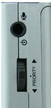
text_image
K ← PRIORITY ←IRT-60 remote control features
- Moving the priority switch Up/Down will control the volume of the line inputs.
- A momentary tap of the priority switch will duck down the line inputs 15dB. The receiver front panel power switch changes to a blinking PURPLE. A second tap will restore line input back to normal.
- Hold in priority switch for 4 seconds closes the contact closure on the Security Alert output. The receivers front panel power switch changes to blinking GREEN. Holding the button down for another 4 sec. returns the contact to normal.
features
• Condenser microphone element
• Power "on/off" switch
- Battery level indicator—LED
- Channel "A" or "B" selectable
• 10 high-power emitting diodes
- Diodes at top and bottom of handle for increased Coverage (2 Top aimed out, 6 Bottom 360^ , 2 Bottom aimed down)
- 360° IR radiation for assured connectivity
- Two "AA", Duracell, rechargeable NiMH batteries
natural_image
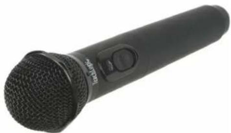
Black handheld microphone with mesh grille and control knob (no visible text or symbols)IRH-35 handheld transmitter
The Handheld Microphone Transmitter (IRH-35) is most applicable for student use or direct presentation. It has an “on/off” switch and a battery level indicator LED; Green=useable charge, Red=low battery. The transmitter has 10 emitting diodes: 8 around the bottom of the handle, and 2 toward the top of the handle. The metal housing provides low handling noise and insures durable longevity.
components
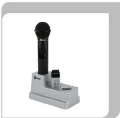
BRC-60 drop-in battery charger
This stylish desktop drop-in charging station makes it convenient and easy to recharge both Sapphire Pendant and Handheld Microphones. Charge one IRH-35 handheld transmitter and up to two IRT-60 Sapphire transmitters simultaneously. Charging indicator lights illuminate Red when charging, and Green when fully charged. The power LED illuminates Blue when plugged in.
natural_image
Exterior view of a handheld electronic device with a black and white body (no visible text or symbols)ICS-55 ceiling sensor
The ceiling sensor is the preferred infrared sensor for optimum performance. This is the unit that needs to be installed on the ceiling. It comes with a mounting/support bracket and 50 feet of plenum rated cable with RCA connector on each end. The ideal location for the dome sensor would be in the center of the ceiling. This will provide a clear signal path for the IR transmission from the transmitter to the dome sensor without obstruction. In addition, you will have 360^ coverage and will minimize the transmission distance for more reliable performance. It collects the infrared transmission signal via 6 large detecting diodes.

natural_image
Close-up of a dark circular object on a tiled floor with intersecting diagonal lines (no text or symbols visible)power "on" LED
Green light indicates that the sensor is receiving power from the receiver.
sensor cable
A cable connects the sensor to the receiver. The cable is dual-shielded with a male RCA connector on each end and is plenum rated.

natural_image
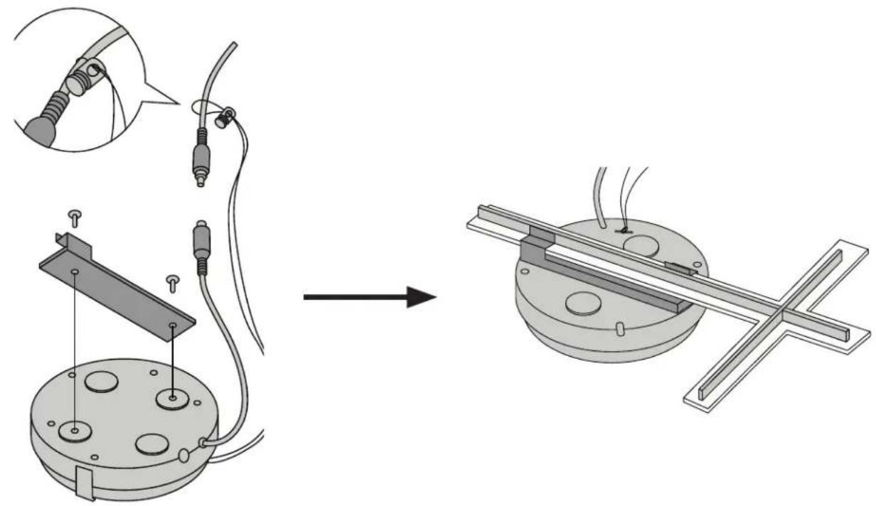
Coiled cable with two black connectors at ends, no visible text or symbolsceiling sensor installation
The ideal location for the ceiling sensor is in the center of the ceiling. This will provide a clear signal path for the IR transmission from the transmitter to the dome sensor without obstruction. In addition, you will have 360^ coverage and will minimize the transmission distance for more reliable performance.
Installation 1 - Attach to T-bar Rail
natural_image
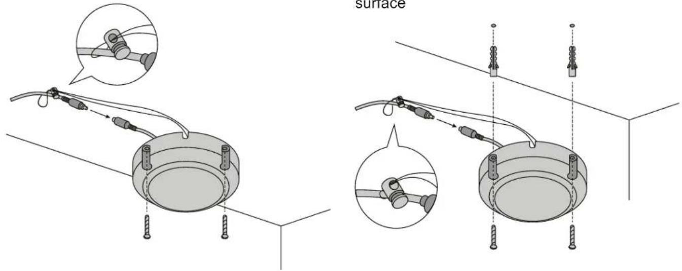
Technical illustration of a mechanical assembly process showing wire connection and mounting mechanism (no text or symbols)Installation 2 - Attach to wood surface Installation 3 - Attach to drywall or concrete surface
text_image
surfacespeaker installation
installing planning
- Amplifier/Receiver: Choose location the based on accessibility requirements and wiring constraints for power, speakers, and audio devices.
- Ceiling Sensor: Locate in the center of the ceiling; maintain line of sight; keep away from direct light and electrical interference.
- Speakers: Mark location for wall mount vs. ceiling mount, and confirm wiring run to the amplifier. Ensure speakers evenly cover the listening area.
- Integrations/Connections: Confirm location of other systems you plan to connect to the amplifier such as audio devices, intercom connections, fire alarm, noting how the wiring needs to run.
- Microphones/Charger: Confirm microphone charging location for daily use/charging.
The IMA-120 has two channels of amplified audio, rated for a minimum 4-ohm speaker load (two 8-ohm speakers each). There is one blue phoenix style speaker connector on the back panel, providing one pair of speaker terminals. When using 4 speakers they must be wired in parallel.
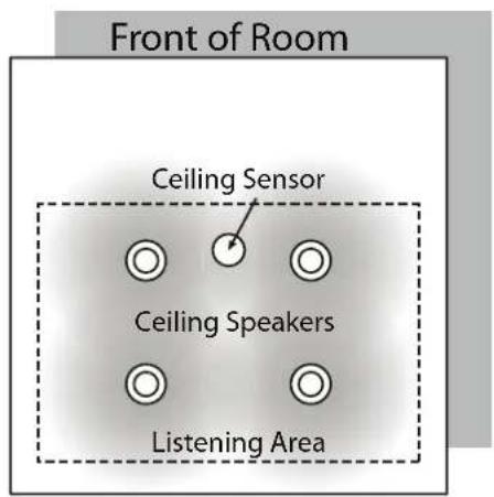
ceiling speaker installation
- Determine the listening area based on where students are seated.
- Divide listening area into quadrants.
- Locate and identify the center most tile in each quadrant to ensure even distribution of sound.
text_image
Front of Room Ceiling Sensor Ceiling Speakers Listening Area
natural_image
Grid pattern with four black dots at intersections of dashed lines (no text or symbols)SP-628
- Lay ceiling tile face down on clean flat surface.
- Lay tile bridge on ceiling tile and center it.
- Trace and cut the large hole using a keyhole or drywall saw.
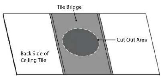
text_image
Tile Bridge Back Side of Ceiling Tile Cut Out Area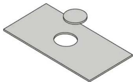
natural_image
3D illustration of a rectangular plate with two circular holes, no text or symbols presentspeaker installation
- Strip the speaker cable ends, approx. 12 .
- Route speaker wire from speaker opening to amplifier.
- Reinstall ceiling tile with tile bridge in place above the hole.
- Pull speaker cable back down through speaker hole.
- With a pointed tool or paper clip, lift up and remove speaker grill and set aside to avoid damage
- Set speaker on top of ladder and connect speaker wire.
- Observe speaker polarity, connect Red wire to (+) terminal and black wire to the (C) terminal.
- For locations where earthquake or a safety restraint is required, make the attachment to the speaker and ensure it's secure.
- With the mounting clamps folded back, position speaker into speaker hole.
- With a #2 Phillips screwdriver, tighten the quick clamps.
Mounting Screws
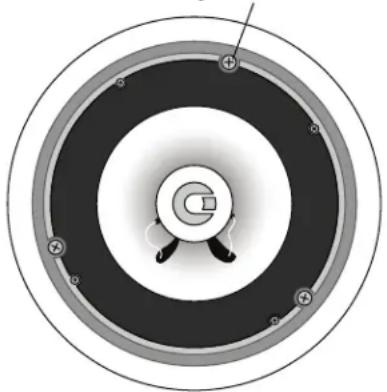
natural_image
Circular diagram with concentric rings and central circular element, no visible text or symbols-
Reinstall speaker grille and remove any soil or fingerprints.
-
Repeat steps 7-16 for other speakers.
-
See "final connection" section to finish installation.
SP-628L
- Lay ceiling tile face down on clean flat surface.
- Lay the SP-628L on the tile with flat end (the opposite end of the integrated T-bar) flush with the end of the tile.
- Mark opposite end where you will make the cut. Mark the two opposite ends of the tile.
- Take care to mark where the SP-628L integrated T-bar connects to the assembly.
- Connect the marks with a level or flat object to ensure you draw a straing line across the tile.
- Cut the tile using a drywall saw.
- Set speaker on top of ladder and connect speaker wire.
- Place speaker in the ceiling ensuring it's secure.
- For locations where earthquake or a safety restraint is required, make the attachment to the speaker and ensure it's secure.
- Replace ceiling tile.
- See "final connection" section to finish installation.
speaker installation
installing SP-2000 wall mount speakers
- First observe the shape of the room: ceiling height, door locations, windows, mounting surface, and seating area.
- Ordinary installation would be to locate the speakers on each side wall approximately even with the front row of listeners.
- It is recommended to mount the speakers a minimum of 6 feet above the floor. Note: In a room with 10' ceilings, a mounting height of 9.5' is ideal.
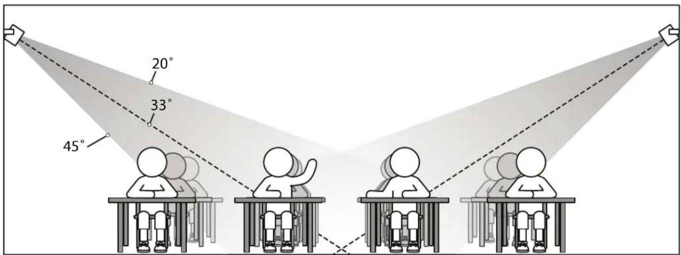
text_image
20° 33° 45°- Install the mounting brackets on wall in the vertical (up/down) orientation.
- Mount brackets using the appropriate hardware
- Insert speaker with the tweeter in upper position.
- Secure speaker in bracket with the hand fasteners.
- Orient each speaker toward the center of that half of the listening area and tighten fasteners.

flowchart
graph TD
    A["Wall Speakers"] --> B["Ceiling Sensor"]
    B --> C["Receiver Amplifier"]
    C --> D["Front of Room"]
    style A fill:#f9f,stroke:#333
    style B fill:#ccf,stroke:#333
    style C fill:#cfc,stroke:#333
    style D fill:#fcc,stroke:#333
- Strip speaker cable ends 12 " and connect to speaker.
- Observe speaker polarity: Connect (+) wire (with printed writing) to (+) terminal and (-) wire (unprinted & textured) to the (-) terminal.
- Route speaker cable to the receiver/amplifier in a safe, least visible, tidy manner.
- See "final connection" section to finish installation.
speaker installation
final connection of the system
With receiver/amplifier located, speaker and sensor cables neatly routed, we are ready to complete the installation.
- Cut the speaker wire to the appropriate length
- Strip about 3/8" off the end of each speaker wire.
- Twist the wire and if you have a soldering iron, tin the wire ends
- Unplug the phoenix connector from amplifier. Reference amplifier insert diagram on amplifier (Figure H) (+) wire (with printed writing) into either outside (+) terminal.
- Plug the other (-) wire into center (-).
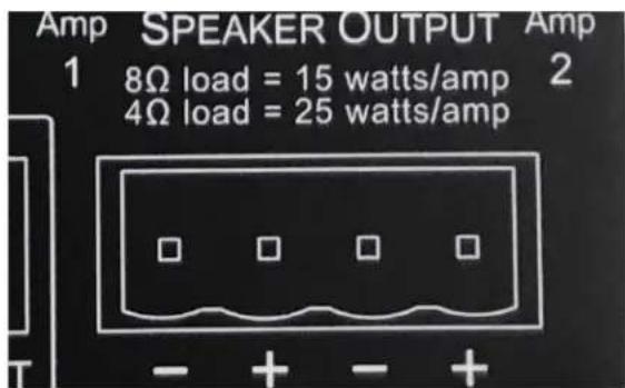
text_image
Amp SPEAKER OUTPUT Amp 1 8Ω load = 15 watts/amp 2 4Ω load = 25 watts/amp - + - +Figure H Speaker Output Phoenix Connector
- Tighten set screws.
- Repeat for other pair and insert plug firmly into speaker output receptacle.
- Plug amplifier power supply into AC outlet.
- Connect audio sources and set output to desired levels.
page mute/pass through
The Page Mute feature allows you to connect the TeachLogic amplifier to the school paging/intercom system for muting purposes. A simple connection between the in-classroom paging speaker (typically 25v, 70v or 100v) and the TeachLogic page input will mute all the inputs and pass the page to the speakers connected to the TeachLogic amplifier. System resumes audio (slowly ramping up volume) 6 seconds after no additional page signal is detected.
KEY SPECS (based on 25 V paging systems)
• Page signal required to activate mute function: 6.0 V
- The impedance of the IMA-120 is 160 Kohms in the 25V switch position, and 180 Kohms in the 75 and 100V switch positions.
- Power draw = 0.004 Watts or less (power = voltage*voltage/impedance, or 25*25/160,000).
CONNECTION
- Tap/Splice page speaker's wire and connect to our amp via 2-pin Phoenix connector.
- Determine the signal level of the paging system (25v, 70v, or 100v) and set the slide switch to the appropriate speaker level setting.

text_image
100V 70V 25V PAGE INPUTFigure I: impedance selector / page input Phoenix Connector
- With the TeachLogic amplifier turned ON, send a page signal through the page input.
- Adjust the page input SENSITIVITY control, located on front panel, so that an incoming page/intercom signal will override any audio (mics, line, etc) plugged into the TeachLogic amplifier.

text_image
POWER BUTTON PAGE SENSITIVITYFigure J: page sensitivity control
PASS-THRU FUNCTION
The amplifier will pass the paging audio through the classroom audio speaker(s) connected to it. Note that you may use the classroom audio system speakers in addition to or in lieu of dedicated paging speaker.*
remote control of audio inputs
CPS-120/CPR-125 controller
Audio levels very often need to be adjusted when switching from computer audio to DVD players and other audio sources.
Such operations as level UP, DOWN and MUTE are easily accomplished via the eight button controller and touch rotary dial, as shown here. This allows the receiver/amplifier to be placed in an area or compartment that is not easily assessed by the user.
No set up is required for these touch panels to operate. They are preprogrammed right out of the box.

text_image
TeachLogic M- MICA MCD AUX IN1 AUX IN2 LINE OUT BT AUX MIC AUX IN 2 MIC MUTECPR-125
The CPR-125 has an additional RJ-45 connection to connect to an intercom system. This colocates the audio controls with the wall-mounted paging buttons into one convenient panel.
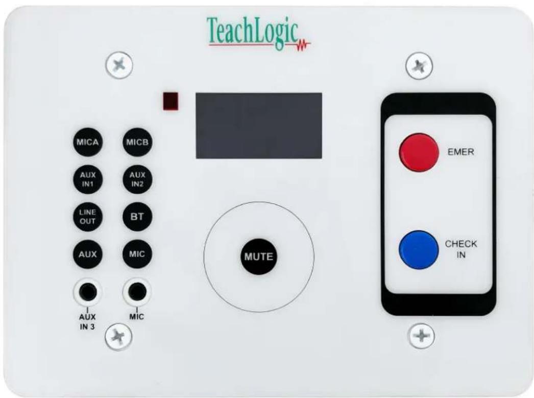
text_image
TeachLogic MICA MICB AUX IN1 AUX IN2 LINE OUT BT AUX MIC AUX IN 3 MIC MUTE EMER CHECK INIMPORTANT
When any remote panel is connected, RS-232 switch must be in "ON" position.
When panel is not connected, RS-232 switch must be in "OFF" position for amplifier controls to function.
CPS-120/CPR-125 panel operation
- Connect cable between amplifier RJ-45 and remote touch panel RJ-45. Please note that the CAT5 cable between Matrix and controller should be no more than 50 ft (15 m).
- Place RS-232 switch in the "ON" position to activate touch panel.
- When wall plate power is on, the LCD screen will illuminate the TeachLogic _# logo.
- The LCD screen will illuminate in two brightness levels, DIM (power save mode) and ON (full brightness).
- To activate the screen press any button to turn the screen ON.
- When the LCD screen light is ON, you can press any of the eight available input source buttons to adjust the volume.
volume control
EXAMPLE:
Aux input volume adjust:
**Please note that you can only adjust the volumes when the screen light is ON**
-
Depress AUX button on touch control panel. The AUX and level indicator will appear in the LCD window.
-
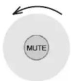
Touch the rotary control in a clock wise direction to increase volume.
Volume Up
- Touch the rotary control in a counter clock wise direction to decrease volume.
Volume Down
- MUTE control: Press the "MUTE" button
- The screen indicates "AUX MUTE" and starts to blink.
Press the "MUTE" button again to return to the present volume.


text_image
AUX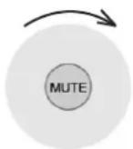


text_image
AUXremote control of audio inputs: RS-232
RS-232
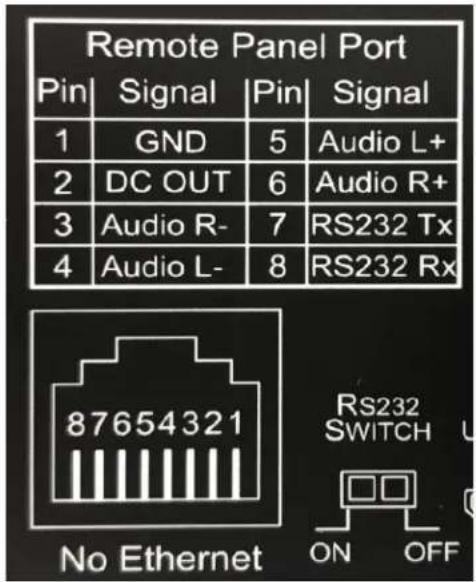
The IMA-120 Matrix can accommodate 3rd party remote control panels that connect via RJ-45. Follow the pin out digram and Hex code chart to ensure your control panel is wired and programmed properly.
text_image
Remote Panel Port Pin | Signal | Pin | Signal 1 | GND | 5 | Audio L+ 2 | DC OUT | 6 | Audio R+ 3 | Audio R- | 7 | RS232 Tx 4 | Audio L- | 8 | RS232 Rx 87654321 No Ethernet RS232 SWITCH ON OFF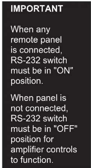
text_image
IMPORTANT When any remote panel is connected, RS-232 switch must be in "ON" position. When panel is not connected, RS-232 switch must be in "OFF" position for amplifier controls to function.RS-232 codes
Baud Rate : 9600
Parity Bit : NONE
Data Bit : 8
Stop Bit : 1
Function HEX
Power:TOGGLE 4c 69 6e 6b 78 3a 50 6f 77 65 72 3a 54 4F 47 47 4C 45 0D
Gain ACH UP 4c 69 6e 6b 78 3a 47 61 69 6e 3a 41 43 48 3a 55 50 0D
Gain ACH DOWN 4c 69 6e 6b 78 3a 47 61 69 6e 3a 41 43 48 3a 44 4f 57 4e 0D
Gain ACH MUTE 4c 69 6e 6b 78 3a 47 61 69 6e 3a 41 43 48 3a 4d 55 54 45 0D
Gain BCH UP 4c 69 6e 6b 78 3a 47 61 69 6e 3a 42 43 48 3a 55 50 0D
Gain BCH DOWN 4c 69 6e 6b 78 3a 47 61 69 6e 3a 42 43 48 3a 44 4f 57 4e 0D
Gain BCH MUTE 4c 69 6e 6b 78 3a 47 61 69 6e 3a 42 43 48 3a 4d 55 54 45 0D
Gain LINE IN1 UP 4c 69 6e 6b 78 3a 47 61 69 6e 3a 4c 49 31 3a 55 50 0D
Gain LINE IN1 DOWN 4c 69 6e 6b 78 3a 47 61 69 6e 3a 4c 49 31 3a 44 4f 57 4e 0D
Gain LINE IN1 MUTE 4c 69 6e 6b 78 3a 47 61 69 6e 3a 4c 49 31 3a 4d 55 54 45 0D
Gain LINE IN2 UP 4c 69 6e 6b 78 3a 47 61 69 6e 3a 4c 49 32 3a 55 50 0D
Gain LINE IN2 DOWN 4c 69 6e 6b 78 3a 47 61 69 6e 3a 4c 49 32 3a 44 4f 57 4e 0D
Gain LINE IN2 MUTE 4c 69 6e 6b 78 3a 47 61 69 6e 3a 4c 49 32 3a 4d 55 54 45 0D
Gain LINE OUT UP 4c 69 6e 6b 78 3a 47 61 69 6e 3a 4c 45 4f 3a 55 50 0D
Gain LINE OUT DOWN 4c 69 6e 6b 78 3a 47 61 69 6e 3a 4c 45 4f 3a 44 4f 57 4e 0D
Gain LINE OUT MUTE 4c 69 6e 6b 78 3a 47 61 69 6e 3a 4c 45 4f 3a 4d 55 54 45 0D
Pairing a Bluetooth mobile device to CPS-120 or CPR-125 Touch Panel
This display means the Bluetooth device is not powered.
- Press and hold "BT" source button for 3 seconds to power the Bluetooth on.
This display means the touch panel is ready to pair with your Bluetooth device.
- Search Bluetooth setting on your mobile device for "TeachLogic".
Each Touch Panel has a unique Serial Number on the panel display.
Look for SN: TeachLogic-00000XXX and pair that number with your device.
This display indicates that your mobile device and Touch Panel are in the pairing process.
This display indicated your device and the Touch Panel are paired.
**Please note that your device will also control the volume.**
Bluetooth will automatically power off if no signal is received after about 10 min.
To connect a different Bluetooth device, hold "BT" source button for 3 seconds and all "BT" action will be stopped.
After completing this step, another mobile Bluetooth device can be connected to the TeachLogic CPS-120 or CPR-125 touch panel.


text_image
OK PRIORITY OK
flowchart
graph TD
    A["Normal"] --> B["Emergency"]
    C["NC"] --> D["NO COM"]
    E["SECURITY ALERT"] --> F["Three warning icons"]
security alert features
SYSTEM BEHAVIOR
When the Sapphire's "Priority" button is pushed/held for 5 seconds, it sends a signal to the ceiling sensor which passes through the amp to the security alert inter face (an electric relay). The relay contacts opens or close (depending on the normal status) to pass the signal through the paging system as if the paging system's wall-mounted button was being pressed. The amplifier functions normally during the alert, e.g. there is no change to audio input/output volume change nor does the system produce any sound
KEY SPECS
- Contact closure, normally open or closed.
- Field programable for 1-pulse and 4-pulse systems
- Amplifier power LED blinks green when the alert is received
- Functions on primary teacher microphone (Channel A) in each room.
CONNECTION
Uses wire from paging manufacturer's wall-mounted call button panel to connect to amplifier via 3-pin Phoenix connector: COM | NORMALLY OPEN | NORMALLY CLOSED.
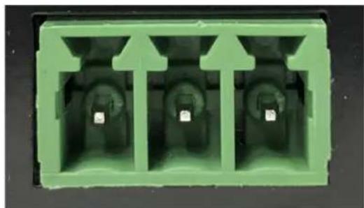
natural_image
Green plastic electrical connector housing with three slots and mounting holes (no text or symbols visible)system operation
Now that the system is installed and connected, we are ready to plug it in and test its performance. The testing will be done using an IR transmitter (Sapphire or Handheld) to confirm good connectivity and quality audio.
system operation
It is best to have a second person help you set the gain levels for the audio sources as the teacher does not need to hear his/her own voice or audio for it to be working properly.
- Plug in the Matrix. Note that the power is always on.
- Confirm power to sensor by verifying the Green LED on edge of sensor is illuminated.
- Set volume of Ch A volume control to mid scale (12 o'clock).
- Set volume control on side of Sapphire transmitter to "Normal" level.
- Switch on by pressing and holding "TL" button until it lights up.
- Observe that the "TL" LED is solid blue, which indicates it is transmitting.
- Have another person sit/stand under or in front of a speaker.
- Slowly adjust "Ch A" volume on Matrix while talking into microphone.
- Adjust to desired listening level.
CAUTION: Beware of feedback. If feedback occurs, dial down gain control until it goes away.
- Walk around the room while talking into microphone to confirm good connectivity.
- Test the mute function by briefly pressing the Sapphire "TL" power button once (flashing blue).
- Briefly press power button again. The light should return to solid blue.
- Upon completion of performance test, the installation is complete.
CHANGING MICROPHONE CHANNELS
If you're using 2 Sapphire microphones in a single room, you'll need to change one to channel "B" (All Sapphire mics are shipped in channel A). Handheld microphones are always shipped in channel "B" setting.
Sapphire: There is an “A–B” switch in the battery compartment. Remove battery cover on back, lift up battery and locate the switch. Make the change.
Handheld: Unscrew barrel and remove. Note "A–B" switch on side of battery holder. Make the change.
SAPPHIRE "TL" POWER BUTTON LED LIGHT STATUS
- Solid Red: OFF
- Solid Blue: ON
• Solid Purple: External devices quieted
• Solid Red: Battery is low - Solid Green: Occurs when charging. Indicates battery is charged.
- Flashing Blue: Microphone muted
basic troubleshooting
| Problem Solution | |
| Amlifier controls not functioning | Turn RS-232 switch to "off" position. Reference RS-232 part of manual |
| System is turned “on” but there is no sound | Verify AC power; the Blue LED lights when turned “on” Check if system has been unplugged Check circuit breaker Call maintenance for assistance |
| System has power but no sound | Turn “on” microphone/ transmitter and ensure the “TL” is solid blue. If different color, then needs to be charged or a new battery if it's not holding a charge. Check for IR transmission. If the amplifier is receiving a signal presence the mic channel indicator will be illuminated Orange. Ensure the Green LED on the ceiling sensor is illuminated. If sensor LED is not lit; sensor has been disconnected or power output to sensor has failed (Receiver/amplifier needs to be replaced) |
| Voice is distorted and/or signal drop-out occurs | Check the charge on your batteries. Verify that the diodes on transmitter or sensor are not being covered or that there is no obstruction between transmitter and sensor . |
| contactIf your problem persists and this guide has not resolved the issue, contact customer service for additional assistance. (760) 631-7800 support@teachlogic.com |
warranty
Please refer to www.teachlogic.com/warranty

TeachLogic™
1-760-631-7800
support@teachlogic.com
teachlogic.com