Matrix IMA-121 - Blender TeachLogic - Free user manual and instructions
Find the device manual for free Matrix IMA-121 TeachLogic in PDF.

| Product Type | Blender |
| Brand | TeachLogic |
| Model | Matrix IMA-121 |
| Dimensions (H x W x D) | 15.5 x 7.0 x 7.0 inches |
| Weight | 5.3 lbs |
| Power Supply | 120V, 60Hz |
| Motor Power | 700W |
| Jar Capacity | 1.5 liters (6 cups) |
| Speed Settings | 2 speeds + pulse |
| Pulse Function | Yes |
| Jar Material | Tritan plastic |
| Blade Material | Stainless steel |
| Base Material | ABS plastic with chrome accents |
| Cord Length | 3.3 feet |
| Safety Features | Overload protection, non-slip feet, safety lock lid |
| Color | Black/Chrome |
| Package Contents | Main unit, jar, lid, user manual |
| Warranty | 1 year limited |
| Dishwasher Safe Parts | Jar and lid (top rack) |
| Maintenance | Clean after each use; hand wash base |
| Repairability | Blade assembly replaceable; contact support |
Frequently Asked Questions - Matrix IMA-121 TeachLogic
User questions about Matrix IMA-121 TeachLogic
0 question about this device. Answer the ones you know or ask your own.
Ask a new question about this device
Download the instructions for your Blender in PDF format for free! Find your manual Matrix IMA-121 - TeachLogic and take your electronic device back in hand. On this page are published all the documents necessary for the use of your device. Matrix IMA-121 by TeachLogic.
USER MANUAL Matrix IMA-121 TeachLogic
Matrix ^TM (IMA-121)
Classroom Audio System
Installation Manual
text_image
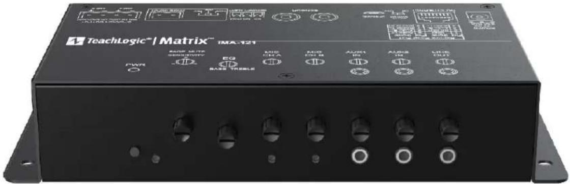
TeachLogic® Matrix™ IMA-121 PWR C BASE TABLE SAMS/MPV EQ BASE TABLE MOS RFA MOS RFA M AUST IN AUST IN CISE IN CISE INWelcome
Congratulations on the purchase of your new TeachLogic® classroom audio system. You can be assured that this product fulfills all specifications and was produced to high quality control standards.
TeachLogic incorporates the latest state of the art technology, employs the most advanced manufacturing methodology and uses only premium quality components to assure many years of reliable performance. We appreciate your confidence by your selection of our product. It is TeachLogic's intent to uphold that confidence by providing factory assistance and reseller support. This manual will help you learn to use and gain the maximum benefit of the system.
We hope you will take the time to review this manual to familiarize yourself with the product operation and features.
TeachLogic, LLC
Longmont, Colorado USA
www.teachlogic.com
Safety Instructions
Read Instructions
All safety and operation instructions should be read before operating this TeachLogic product.
Retain Instructions
Safety and operating instructions should be kept for future reference.
Water & Moisture
This product should not be operated near water.
Heat Environment
Do not subject this product to excessive heat conditions.
Power Source
This product must be connected to an AC power source per the voltage input specified and marked on the power supply.
Do not insert any power cable not provided by the manufacturer into the product. Long prongs can penetrate inside electrical components or current charging conductors.
Certifications


TeachLogic systems are manufactured using lead-free processes and are free of materials harmful to the environment. They conform to European RoHS guidelines for consumer products.
Power Cord Caution
Power cable should be routed clear of foot traffic and supported clear of kinking or abrasion.
Object Protection
Locate the operating unit so it will not be subjected to falling objects or water entry. Do not drill hole in or screw objects into the product except as specified by manufacturer.
Internal Service
User should not attempt to service this product. All internal service must be accomplished by a qualified technician.
Electric Shock
Do not adapt or modify the AC power plug. Do not remove thus lifting the earth ground connection ( 3^rd prong) or use power supply without a connector to a 3-prong grounded outlet.
CAUTION
Recycle—Do not dispose rechargeable batteries in trash. It is unlawful to do so in numerous states. Go Green. Save our resources and do not contaminate.
Contact: Earth911.com 1-800-CLEANUP

CAUTION
RISK OF ELECTRIC SHOCK: DO NOT OPEN

Caution: To Reduce The Risk Of Electric Shock Do Not Remove Cover (Or Back) No User-serviceable Parts Inside Refer Servicing To Qualified Personne
System info
Date of Purchase
Model Number
Serial Number
Notes
Contact
If you should encounter an
unresolved issue, please contact
the TeachLogic customer service
department for further assistance.
760-631-7800 | support@teachtogic.com | teachlogic.com
Limited warranty
For full warranty details refer to teachlogic.com/warranty.
Contents
System Overview....5
System Diagram 6
Installation....7
Installation Planning....7
Connection of Speakers....8-9
Installation of Ceiling Sensor....10
Integration ....11
Page Mute/Pass Through Integration....11-12
RS-232 Feature 13
Security Alert Feature 14-15
Configuration ....16
Final Setup....16
Power Button Lights | Standby Function....17
Troubleshooting ....18
System Specifications....19-20
Front Panel
- Power Button
- Power Indicator LED
- Page sensitivity control
- Bass/Treble equalizer ±12 dB
- CH A Mic Connection Indicator LED
- CH A Mic Volume Control
-
CH B Mic Connection Indicator LED
-
CH B Mic Volume Control
- Line 1 Volume Control
- Line 2 Volume Control
- Line Out Volume Control
- Line 1 Input (3.5mm)
- Line 2 Input (3.5mm)
- Line Output (3.5mm)
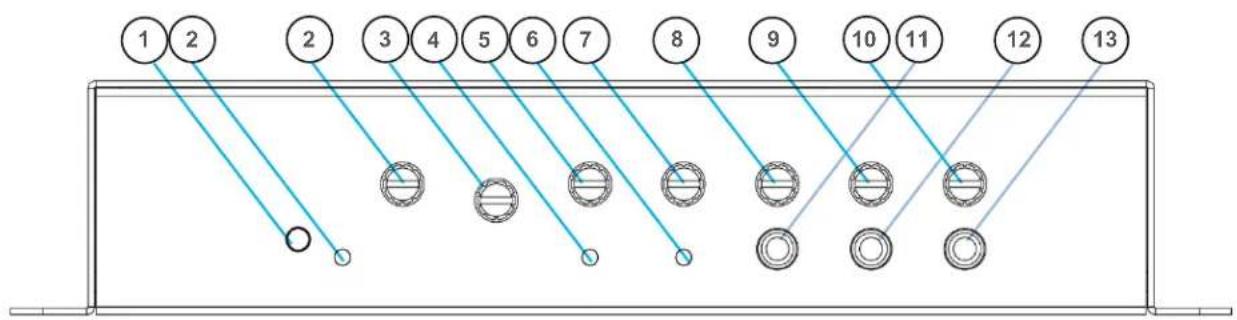
text_image
1 2 2 3 4 5 6 7 8 9 10 11 12 13- Power Input: 19 VDC 3.4A
- RJ-45 Control Panel Jack
- RS-232 Switch (Off/On)
- UPGRADE input Micro USB
-
Two Sensor Inputs (RCA)
-
Security Alert - Com | N.O.| N.C.
- Impedance selector 25V, 70V, 100V
- Page Mute Input - 2-pin Phoenix
- Speaker Output - Two Channel, 4-pinPhoenix connector
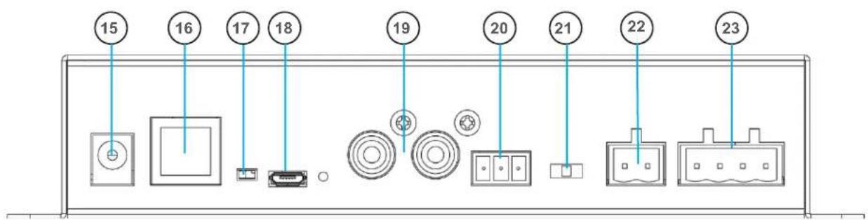
text_image
15 16 17 18 19 20 21 22 23
text_image
CEILING/WALL MOUNT SPEAKERS CEILING SENSOR(S) THIRD PARTY INTERCOM/PAGING SPEAKER 3RD PARTY INTERCOM/PAGING SYSTEM WALL PANEL Emergency Normal Wall mounted call button Output to front office intercom panel via existing intercom cabling CPS-121/CPR-125 REMOTE CONTROL PANEL + - + - PAGE INPUT AS: SEAMAR OUTPUT AND 2 1.00 ON SINEMA OUTPUT AND 2 PWR PAGE MUTE SENSITIVITY IMA-121 IRQ BASS-TREBLE IR MIC1 IR MIC2 AUX1 IN AUX2 IN LINE OUT Power 4.00V 8.00V 6.00V 4.00V 2.00V 1.00V 0.00V 0.00V 0.00V 0.00V 0.00V 0.00V 0.00V 0.00V 0.00V 0.00V 0.00V 0.00V 0.00V 0.00V 0.00V 0.00V 0.00 UP TO 2 MEDIA DEVICES LESSON CAPTURE RECORDER ASSISTIVE LISTENING DEVICE (3.5 mm analog output)The goal of a classroom audio system is to evenly distribute sound throughout the listening area.

text_image
Sound Field Area 65 dB 65 dB 65 dBComponent Placement

- Amplifier: Choose location that supports wiring constraints for power, speakers, ceiling sensor, and audio devices connecting to the amplifier.

- Wall control panel: Locate on a wall convenient for teacher access.

- Ceiling Sensor: Locate in the center of the ceiling; maintain line of sight to teacher locations; keep away from direct sunlight and electrical interference.

- Speakers: The Matrix ^™ can power 4 classroom speakers. Mark location for wall mount vs. ceiling mount and confirm wiring run to the amplifier. Ensure speakers evenly cover the listening area.

- Integrations/Connections: Confirm location of other systems you plan to connect to the amplifier such as audio devices, flat screens, projectors, and communications systems, noting how the wiring needs to run.

- Charger: Confirm microphone charging location for daily use/charging.

text_image
Plenum BoxSpeaker Location
Below are examples of room coverage for two and four speaker installations. For more than 4 speakers, space the next row(s) accordingly.
Ceiling Speakers: Locate and identify the center most tile in each quadrant.
Wall Speakers: First observe the shape of the room: ceiling height, door locations, windows, mounting surface, and seating area. Ordinary installation would be to locate the speakers on each side wall beginning at the front row of listeners, at least 6+ feet above the floor.
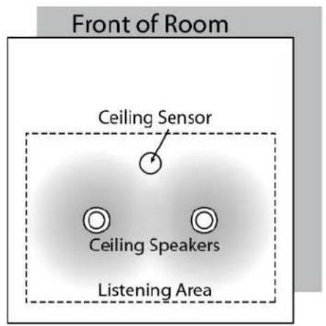
text_image
Front of Room Ceiling Sensor Ceiling Speakers Listening Area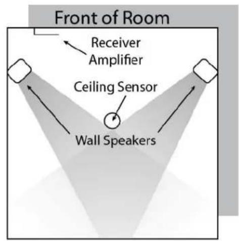
text_image
Front of Room Receiver Amplifier Ceiling Sensor Wall Speakers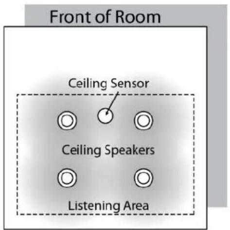
text_image
Front of Room Ceiling Sensor Ceiling Speakers Listening Area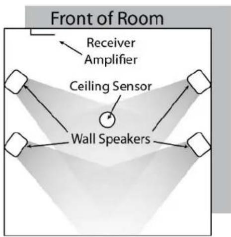
flowchart
graph TD
    A["Wall Speakers"] --> B["Ceiling Sensor"]
    B --> C["Receiver Amplifier"]
    C --> D["Front of Room"]
    style A fill:#f9f,stroke:#333
    style B fill:#ccf,stroke:#333
    style C fill:#cfc,stroke:#333
    style D fill:#fcc,stroke:#333
Connection of speakers
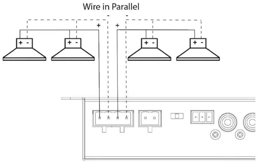
The IMA-121 has two channels of amplified audio, rated for a minimum 4-ohm speaker load (two 8-ohm speakers each, connected in parallel provide 4 ohms impedance).
There is one blue phoenix style speaker connector on the back panel, providing two pairs of speaker terminals.
text_image
Wire in Parallel + - + + - + + - +Installation of Infrared (IR) Ceiling Sensor (ICS-55)
The ideal mounting location is in the center of the room's ceiling. The ideal installation is flush mounted on a white, reflective ceiling like suspended acoustic ceiling tiles. This will ensure 360^ coverage and will minimize the transmission distance for more reliable performance.
For additional coverage, or in large rooms, a second IR sensor may be placed on ceiling or a wall and connected to the second sensor input. As many as three sensors may be powered by the amplifier (use a wye adapter for two of them to connect to one input). The max cable length is 100 ft.
Installation 1 – Attach to T-bar rail
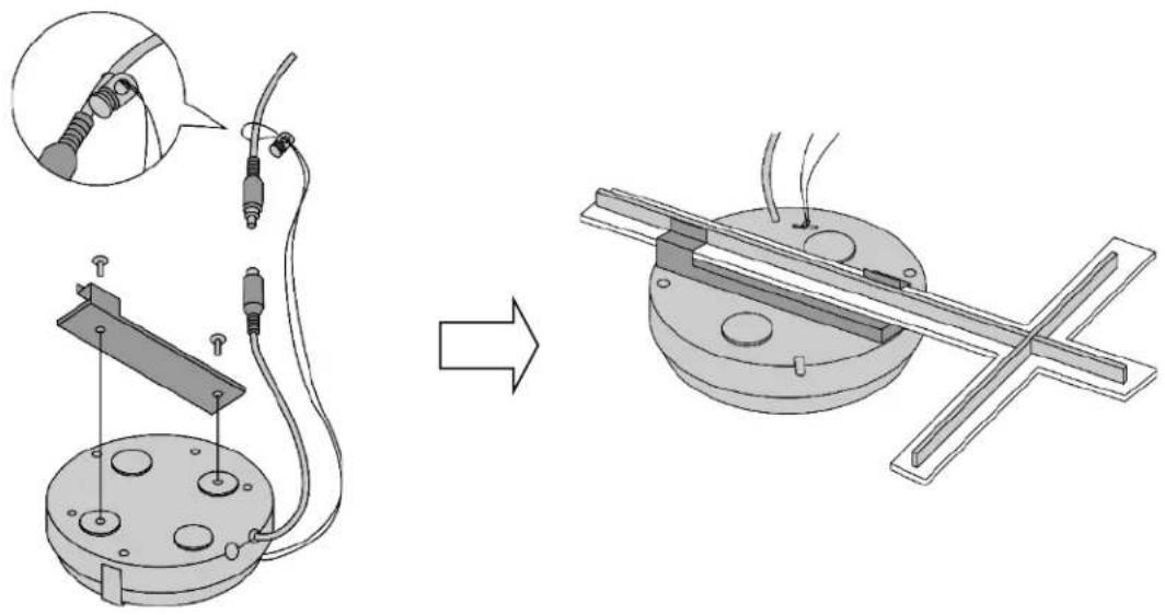
natural_image
Technical illustration showing a mechanical assembly before and after modification, with no visible text or symbols.Installation 2 – Concrete or Drywall Surface

text_image
Technical diagram showing cable installation and wire connection for a suspended lamp, with labeled components and zoomed-in detail views.Installation 3 – Wood Surface
FINAL STEP: Route sensor cable to amplifier and plug into one of the amplifier's two sensor inputs. An illuminated green LED will indicate that the sensor is receiving power from the amplifier.
Page Mute
System behavior for Page Mute
Page Muting causes the amplifier to silence the microphones and audio sources connected to the amplifier when a page signal is detected on the Page Input terminal. When muted, the only audio allowed to pass through is from the paging system, i.e. Page-Pass-Through Function (PPT).
The amplifier can integrate with constant voltage analog paging systems (100V, 70V and 25V) as well as low power VOIP amplifiers (as low as 1/8 watt).
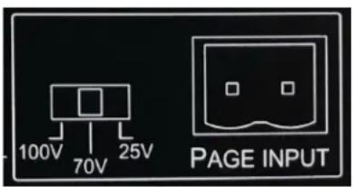
text_image
100V 70V 25V PAGE INPUTConnecting the system:
Before connecting, the installer is responsible for determining that the TeachLogic amplifier impedance is compatible with the paging system.
- Unplug the 2-pin green Phoenix connector.
- Connect a cable from the paging system driving its speakers to the 2 pin Phoenix connector of the Page input.
- Reconnect the 2-pin green Phoenix connector.
- Determine the signal level of the paging system (25V, 70V, or 100V).
- Set the slide switch to the appropriate page speaker level setting.
-
With the amplifier turned ON, send a page to test the mute function.
-
Adjust the sensitivity control to ensure the amplifier senses the page signal, noting that some pages with quiet voices will require greater sensitivity settings. The system will maintain its mute until about 11 seconds after the page signal falls below the threshold for sensing. Thereupon, the wireless mics are unmuted, and other audio levels are ramped up smoothly to their prior volume (before mute).
Table 1. Impedance of Page Input interface and Sensitivity for Mute function
| Switch Position | Nominal Impedance /Power Draw | Maximum Sensitivity (minimum threshold for muting) | Minimum Sensitivity |
| 25V | 160 kΩ / 0.004 W | 3.6 V | >14 V |
| 70V | 180 kΩ / 0.028 W | 8.2 V | n/a |
| 100V | 180 kΩ / 0.056 W | 12.7 V | n/a |

text_image
IMA-121 PAGE MUTE SENSITIVITY EQ PWR BASS TREBLEPage Pass Through
Page-Pass-Through is a feature that passes an audio paging signal through the amplifier and to the connected loudspeakers. Note that you may use the classroom audio system speakers in addition to or in lieu of dedicated paging speaker*.
\*IMPORTANT:
The system does not pass-through paging audio signal to the speakers when the amplifier is powered off (or no power is available).
RS-232 Control Feature
The RS-232 control feature allows the user to remotely adjust the volume (or gain) of all the audio sources connected to the amplifier. Such control may be exercised from a separate wall panel controller or other device. The third-party RS-232 device is connected via three wires to the back panel connector shown to the right: TX/Gnd/RX.
This allows the receiver/amplifier to be placed in an area or compartment that is not easily accessed by the user.
Codes that are required for this setup are available on the teachlogic/com/resources page under "Application Notes" or directly at https://TeachLogic.com/TeachLogic-app-notes-rs-232-control/.
Audio levels very often need to be adjusted when switching from computer audio to DVD players and other audio sources. Such operations as level UP, DOWN and MUTE are easily accomplished via a typical eight button controller. Shown here is a Cables To Go controller.
Connecting the control panel:
-
Connect the control panel wires to the provided 3-pin Phoenix connector.
-
Turn RS232 SWITCH to ON position. This will disable the function of the input volume/gain control knobs on the front of the amplifier.
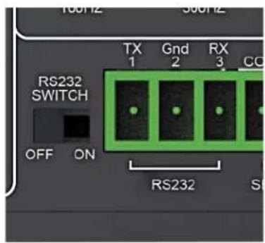
text_image
100Hz 500Hz RS232 SWITCH TX 1 Gnd 2 RX 3 CO OFF ON RS232 S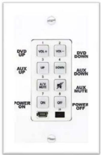
text_image
DVD UP AUX UP POWER ON 1 2 VOL + 3 4 UP DOWN 5 6 A/V MUTE 7 8 ON OFF IN DVD DOWN AUX DOWN AUX MUTE POWES OFFIMPORTANT
When any remote panel is connected, RS-232 switch must be in "ON" position.
When panel is not connected, RS-232 switch must be in "OFF" position for amplifier controls to function.
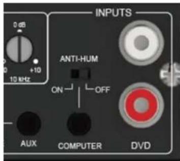
Anti-Hum Feature
The rear panel input port labeled "Computer" has a switchable feature to eliminate or reduce hum sounds often present when computers are connected to external amplifiers. The hum is known as a ground loop hum and may be present if the computer and amplifier have electrical grounding differences. The telltale characteristic is that it is 60 hertz (a somewhat low tone.) Inside the amplifier is a ground isolating balun that may reduce or eliminate the hum when switched ON. If not needed, it is getter the leave switched OFF as the sound quality for the connected device will be slightly better in this case.
text_image
INPUTS ANTI-HUM ON OFF AUX COMPUTER DVDSecurity Alert Feature
The Security Alert feature allows a user with a TeachLogic wireless microphone to summon help or indicate to administration personnel of an urgent situation in the room of that user. The Matrix is designed for a 4-pulse system.

CONNECTION
- Uses wire from paging manufacturer's wall-mounted call button panel to connect to amplifier via 3-pin Phoenix connector: COM | NORMALLY OPEN | NORMALLY CLOSED

text_image
Ceiling Sensor Matrix Amplifier NC NO COM SECURITY ALERT Classroom Wall Call Button Front Office Sapphire Microphone Press/Hold 5 SecondsSYSTEM BEHAVIOR
- When the Sapphire's "Priority" button is pushed/held for 5 seconds, it sends a signal to the ceiling sensor which passes through the amp to the security alert interface (an electric relay).
- The relay contacts opens or close (depending on the normal status) to pass the signal through the paging system as if the paging system's wall-mounted button was being pressed.
- The amplifier functions normally during the alert, e.g. there is no change to audio input/output volume change nor does the system produce any sound
Testing the Security Alert function
To test security alert, you will need an IRT-60 (Sapphire™) microphone.
- Turn on an IRT-60 Sapphire microphone by holding the power button until it illuminates.
- Once the LED is illuminated solid blue, locate the "Priority" switch on the side of the microphone.
- While looking at the amplifier's power button, press & hold the microphone's Priority button for 5 seconds after which time the amplifier's power button will flash green. There will be an audible clicking sound from the amplifier when flashing.
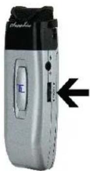
natural_image
Close-up of a silver portable electronic device with black buttons and a blue control panel, no visible text or symbols.To check the mode:
Note the LED color on the power button at the TL logo.
- If power state is ON (Blue LED at power button), press once to set power state OFF (Red LED).
-
If Red, then you may start the process.
-
Press and hold the power button (in Red state) for the entire process.
- After 4 seconds, the LED will change colors.
- Note the number of RED flashes AFTER the GREEN flash.
If one RED after GREEN, then mode is 1-pulse mode. (This will repeat 3 times.)

If four RED after GREEN, then mode is 4-pulse mode. (This will occur 1 time.)

The important part of the sequence is the number of red flashes that follow one green flash.
- Release the power button.
To change the mode:
Whether mode is 1-pulse or 4-pulse, the steps below will change it to the other mode.
- If power state is ON (Blue LED at power button), press once to set power state OFF (Red LED). If Red, then you may start the mode switching process.
- Locate the RS-232 on/off switch on the back panel.
- Press and hold the front panel power button (in Red state) for the duration of the mode switching process. (Figure 3 below)
- Move the RS-232 switch from ON to OFF and back again FIVE times. Then release the front panel power button. (Figure 4 below)
The process requires 5 full cycles of the RS-232 switch while the power button in Red OFF state.
Using the previous process, check the mode to confirm that the Maxim ^™ III is in the desired 1-pulse or 4-pulse mode. If not, repeat the steps above to change the mode.
To change the mode:
Whether mode is 1-pulse or 4-pulse, the steps below will change it to the other mode.
- If power state is ON (Blue LED at power button), press once to set power state OFF (Red LED). If Red, then you may start the mode switching process.
- Locate the RS-232 on/off switch on the back panel.
- Press and hold the front panel power button (in Red state) for the duration of the mode switching process. (Figure 3 below)
- Move the RS-232 switch from ON to OFF and back again FIVE times. Then release the front panel power button. (Figure 4 below)
The process requires 5 full cycles of the RS-232 switch while the power button in Red OFF state is held in.
Using the previous process, check the mode to confirm that the Maxim ^™ III is in the desired 1-pulse or 4-pulse mode. If not, repeat the steps above to change the mode.
Final Setup
Now that the system is installed and connected, turn the system "ON" and test its performance.
The testing will be done using an IR (infrared) microphone (Sapphire ^™ or Handheld) to confirm good connectivity.
AMPLIFIER
- Connect power supply to amplifier, then plug into outlet.
- Turn the amplifier ON by pushing the power button. The LED illuminates solid blue when the amplifier is powered ON.
- Confirm there is power to the IR ceiling sensor: A green LED on edge of sensor should be illuminated that indicates it is receiving power.
- Set all gain/volume dials to mid scale (12 o'clock position)
IRT-60 (SAPPHIRE) MICROPHONE SETUP
- Confirm "Ch A" volume dial is at mid scale (12 o'clock position)
- Slide gain/volume control switch on Sapphire to "Normal" setting.
- Press and hold power mic button until the LED light illuminates solid blue.
- Observe Sapphire power LED. Solid blue indicates power is on and mic is transmitting.
- Observe amplifier Ch A indicator LED. It should be green, indicating a connection between the microphone and ceiling sensor.
- If using two IRT-60 microphones in the same room, one must be changed to channel B to avoid interference. Watch the how-to video.
Note: Next steps should be performed with a second person as the listener
- Stand under or in front of a speaker.
- Hold the microphone with the top at your collarbone and observe the speaker volume in the room by speaking in a natural voice.
- Raise the volume on Ch A until feedback begins, then reduce volume to an acceptable level and until indications of feedback have stopped.
- Walk around the room while talking into microphone to confirm good connectivity and sound levels and lack of feedback under/in front of each speaker.
IRH-35 HANDHELD MICROPHONE SETUP
- Confirm "Ch B" volume control is set to mid-scale (12 o'clock position)
• Power on microphone using ON/OFF switch. - Observe LED above mic switch. Solid green indicates power is on and ready to use.
- Observe amplifier Ch B indicator LED. It should be green, indicating a connection between the microphone and IR ceiling sensor.
- Hold the microphone about 3 inches from the mouth, above chin level and perform voice test.
- Raise the volume on "Ch B" until feedback begins, then reduce volume to eliminate all feedback.
- Walk around the room while talking into the microphone to confirm good connectivity and sound under/in front of each speaker without feedback.
Once complete, charge microphones so they are ready for use.
Power Button Operation
The main power button on the amplifier's front panel has multiple indications as shown in the table below.
| Red, solid | Off state; power is still supplied to USB port on back panel used to charge microphones |
| Blue, solid On | |
| Blue flashing | Page received and audio sources muted |
| Amber, solid | In Standby (or “Sleep”) mode. See below |
| Purple, flashing | System in Teacher Priority mode with all line inputs lowered in volume to allow microphones to be better heard. The Sapphire mic on Channel A can trigger this mode with a single press of its Priority button (toggles mode on and off) |
| Green Flashing | Security Alert activated |
System Standby Function
Standby Mode is a feature that reduces power consumption after the amplifier has not been used to amplify audio signal for a period of two hours. After entering the automatic standby mode, the amplifier displays an amber light at power button.
Normal ON mode may be resumed by
- speaking into a microphone that is on,
- sending an audio signal into one of the line inputs *such as a projector or flat panel audio signal), or
- pressing the power button once.
It may take a few seconds for the normal mode to resume after one of these actions is taken. A page signal can also “wake” the amplifier, but to hear the full first page of a morning, be sure to wake it first with one of the methods above since, or the initial several seconds may be missed if there are no other paging speakers provided to deliver the page audio.
Troubleshooting
| Problem | Solution |
| System will not power “ON” | Verify AC power; the power button will illuminate Blue when turned ONCheck if system has been unplugged; reconnect to power outlet or use another device to ascertain power available at outletCheck circuit breakerCall maintenance for assistance |
| System is turned “ON” but there is no soundorSystem is in standby and does not “wake up” | Turn “ON” microphone/ transmitter; the power button will illuminate to solid Blue when turned ONIf the power button is illuminated red, the battery is lowEnsure the mic is not muted (blinking blue light on mic indicates it is muted)Ensure gain/volume control knob on amplifier/receiver is turned up to mid-scale (12 o’clock position)On amplifier/receiver, ensure a green LED is illuminated just below Ch A or Ch B knob (depending on the microphone used).If no LED is illuminated:Check the green LED on the ceiling sensorIf sensor LED is not lit:Sensor has been disconnected (check cable plug ends), orPower output to sensor has failed (Sensor or amplifier may need to be replaced) |
| Voice is distorted and/or signal drop-out occurs | Verify that the sensor is not being coveredVerify there is no obstruction between microphone and sensorEnsure there is no direct sunlight on sensorEnsure no other IR mics in room are turned onIf sensor is mounted on a dark surface or without a flush ceiling surface, reception can be hampered. |
Matrix™ (IMA-121)
| Receiver Input | Infrared FM |
| Modulation | FM Wide-band |
| Reception Frequencies | Ch. A: 2.08 MHz | Ch. B: 2.54 MHz |
| Infrared Wavelength | 850 nm |
| Tone Signal | Ch. A: 32.768 kHz |
| De-emphasis | 50 μs |
| Frequency Response | 40 Hz, -18 kHz, ± 3 dB |
| S/N Ratio | >65 dB |
| THD | <1% @1 kHz |
| Nominal Deviation | ± 10 kHz |
| Maximum Deviation | ± 25 kHz |
| External Sensor Input | Two, RCA |
| Connectivity Coverage | 1,600 Sq. Ft. | 50ft. line of sight |
| Line Inputs | Two Line Level, Aux input with +10dB Gain Control, 3.5mm |
| Line Output | One 3.5mm Line Level output with Gain Control |
| Page Over-Ride | Input:100v, 70v, 25v, 2pin Phoenix |
| Sensitivity | Level Control |
| Security Alert | Contact Closure (COM, N/O, N/C) |
| Equalization | Bass/Treble Control, ±12 dB |
| Output Power | Two digital Amplifiers, 25 watts ea, 50 Watts total (RMS) |
| Output Impedance | 4Ω min. per channel |
| Output Connection | One Phoenix Connector |
| Power Supply | 19 VDC / 3.4 A CE,CSA and UL Listed |
| Dimensions | 7 1⁄2" W x 4 1/4" H x 1 1⁄2" D |
| Weight | 1 lb 5 oz. |
Power Supply (AC-36)
| Type | Regulated Switching Power Supply, CE, CSA and UL listed |
| Input Voltage | 100-240 volts AV, 47-63 Hz |
| Output Voltage | 19 VDC, 3.43 A |
| Power Output | 65 watts max |
Sapphire (IRT-60) microphone/transmitter specs
| Transmission Carrier | Infrared |
| Transmission Frequencies | 2.08 MHz & 2.54 MHz |
| Channel Selection | Field Switchable |
| Transmitting Diodes | Six |
| Wavelength | 850 nm |
| Modulation | FM Wide-Band |
| Frequency Response | 100 Hz - 10 kHz |
| Pilotone Frequency | 32.768 kHz |
| Peak Deviation | ± 25 kHz |
| Dynamic Range | 95.5 dB @ 2.8% THD |
| Operating Range | 60 Ft. line of sight |
| Latency (mic to speakers) | 0.87 ms |
| Battery Used | Lithium-ion polymer (3.7 V / 620 mAh) |
| Battery Life | 8 hr/Charge |
| External Power Charger | 5 V DC Micro USB Connector |
| Transmission Angle | 180° Conical |
| User Controls | |
| Power (On/Off) | Press & Hold |
| Mute Switch (On/Off) | Momentary Press (blinks when muted) |
| Addt'l Mic Gain Control | Normal, -3 dB, -6 dB |
| Audio Source Vol./Gain | Increase, Decrease |
| Channel Select | (A or B) in battery compartment |
| External Mic/Aux Input | 3.5 mm Line Level |
| Dimensions (H x W x D) | 3.5" x 1.25" x 0.75" |
| Weight | 1.4 oz including battery |
Handheld (IRT-35) microphone/transmitter specs
| Transmission Carrier | Infrared |
| Transmission Frequencies | 2.08 MHz & 2.54 MHz |
| Channel Selection | Field Switchable |
| Transmitting Diodes | Ten |
| Wavelength | 850 nm |
| Modulation | FM Wide-Band |
| Pilotone Frequency | 32.768 KHz |
| Peak Deviation | ± 25 KHz |
| Operating Range | 50 ft. line of sight |
| Power Switch (Slide) | On/Off |
| Battery Charge Level (LED) | Green: Full | Orange: Medium | Red: Low |
| Battery Life | Approx. 7 Hr./Charge |
| Dimensions | 2.125" dia. (Head), 1.4375" dia. (Body), 9.625" H |
| Weight | 10.3 oz. w/ Battery |

natural_image
Abstract white line drawing on gray background with no text or symbolsTeachLogic®
541 Main St., Suite B, Longmont, CO 80501
TeachLogic.com | Support@TeachLogic.com | 760-631-7800