US2-C65 - Speaker SSV Works - Free user manual and instructions
Find the device manual for free US2-C65 SSV Works in PDF.

User questions about US2-C65 SSV Works
0 question about this device. Answer the ones you know or ask your own.
Ask a new question about this device
Download the instructions for your Speaker in PDF format for free! Find your manual US2-C65 - SSV Works and take your electronic device back in hand. On this page are published all the documents necessary for the use of your device. US2-C65 by SSV Works.
USER MANUAL US2-C65 SSV Works
WARRANTY INFORMATION:
All SSV Works enclosures are covered by a limited lifetime warranty against defects in material or workmanship. All SSV Works Electronics are covered by a limited 1 year warranty against defects in material or workmanship. Labor for replacement of defective components is not covered. All SSV Works Speakers are covered by a limited 1 year warranty against defects in material or workmanship. Contact SSV Works for further warranty information.
TOOLS NEEDED FOR INSTALLATION
- 5mm Allen Key
- 8mm Open End Wrench
- 3mm Allen Key
- #2 Phillips Screwdriver

Please read and understand these instructions completely before installation to avoid possible injury, or damage to the accessory or vehicle.
Placement of the pod depends on what type of roll cage you have (factory or aftermarket) and your preference of where you want the pods to be installed. In these instructions, we have installed them on the outside vertical bars at the back of the roll cage.
PARTS LIST IMAGES
natural_image
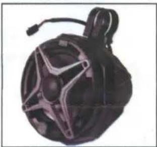
Black and white spherical object with star-shaped cutouts, resembling a helmet or device (no visible text or symbols)- US2-C65 Enclosures (1 pair)
natural_image
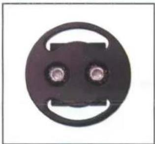
Circular mechanical component with two central holes and a curved handle (no text or symbols)- Dual Mounting Ring Adapter x 2

natural_image
Close-up of a black U-shaped metal clamp with 'SSV SORLS' branding (no additional text or symbols)- Ring Clamp x 4
natural_image
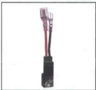
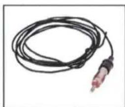
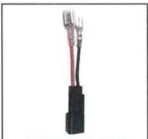
Close-up of a black electrical connector with red and black wires (no visible text or symbols)- Aftermarket Speaker Adapter (comes with unloaded pods only)
natural_image
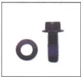
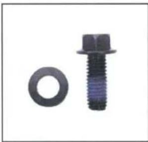
Two mechanical components: a circular bolt and a standard bolt (no text or symbols visible)- M6 Hex Head Bolts & Washers x4

natural_image
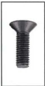
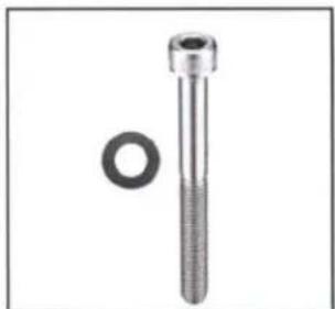
Close-up of a black bolt and a circular nut (no text or symbols visible)- M6 Allen Socket Head Bolts & Washers x4
natural_image
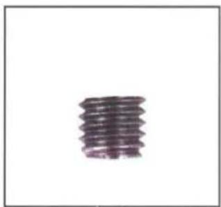
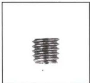
Close-up of a single cylindrical object with no visible text or symbols- M6 Set Screws x 8
natural_image
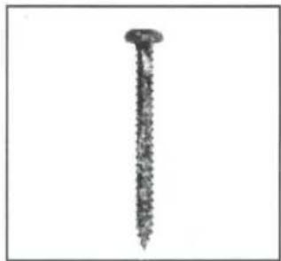
Close-up of a single nail with textured surface (no text or symbols visible)-
7 Screws x 8 (comes with unloaded pods only)
INSTALLATION NOTES
It is recommended to wrap the bag that the clamps come in around the cage before you slide the clamp onto the cage to prevent scratching.
natural_image
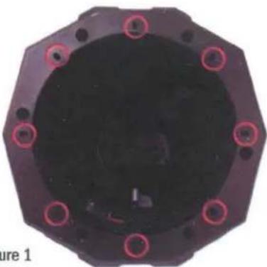
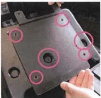
Top-down view of a black octagonal mechanical component with red circular indentations (no text or symbols visible)FOR UNLOADED ENCLOSURES:
If using a different brand speaker, first see if the speaker holes line up with the screw bosses (circled in pink on Figure 1). Be sure to use the 8 supplied SSV Works #7 screws when installing your own speaker.

natural_image
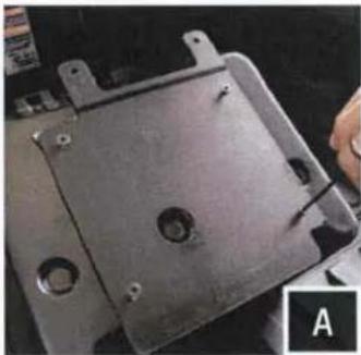
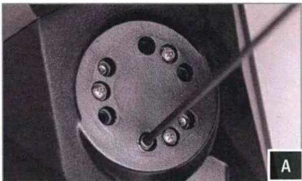
Circular mechanical component with multiple bolt holes and a central hub, labeled 'A' in corner (no text or symbols on the object itself)A. Find the best orientation for the speaker on your bar and screw in the Set Screws in the OPPOSITE holes of where the clamp will install into.
natural_image
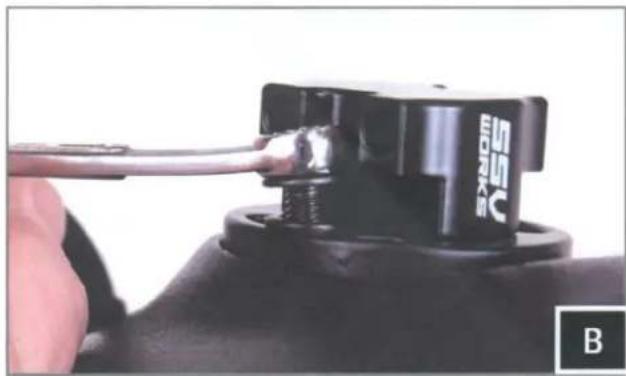
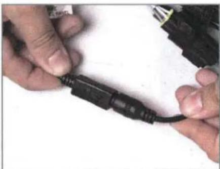
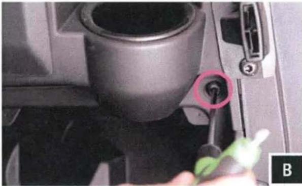
Close-up of a hand holding a black electrical connector with a cable, labeled 'B' in the corner (no readable text or symbols on the component itself)B. Loosely install the clamp base to the cage mount pod with the two (2) M6 hex head bolts and washers, place the cage mount pod in the desired mounting location on the vehicle.
natural_image
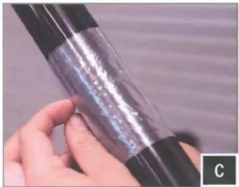
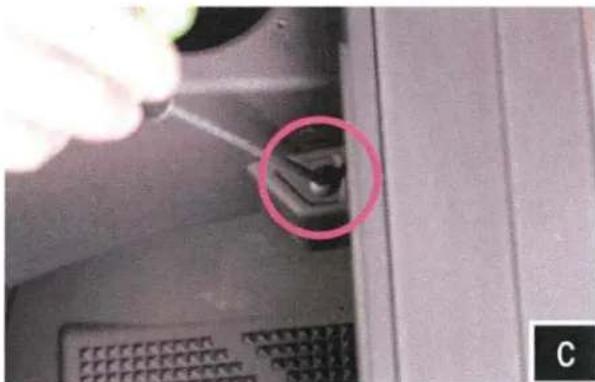
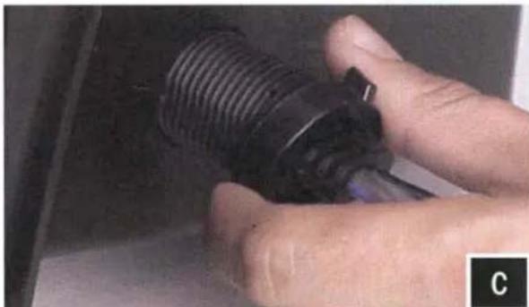
Close-up of a hand holding a transparent cylindrical object with visible internal structure (no text or symbols)C. Place both ring mounting clamps on the cage using the plastic bag to prevent scratching, place the cage mount pod in its final mounting location and secure to the clamps using the two (2) M6 allen socket head bolts and washers with a 5mm allen key.

natural_image
Close-up of hands holding a transparent cylindrical object with black bands (no visible text or symbols)
natural_image
Close-up of a finger pressing a small mechanical component (no visible text or symbols)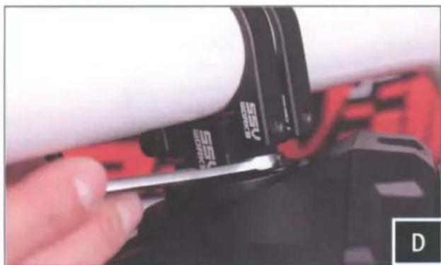
natural_image
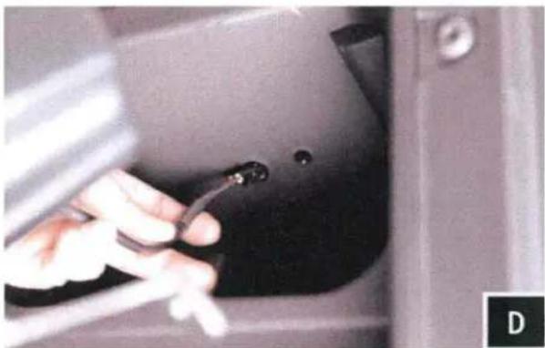
Close-up of a hand using a screwdriver to adjust a cylindrical component (no visible text or symbols)D. Position the speaker to your liking and tighen the hex head bolts by hand with a 8mm wrench.
natural_image
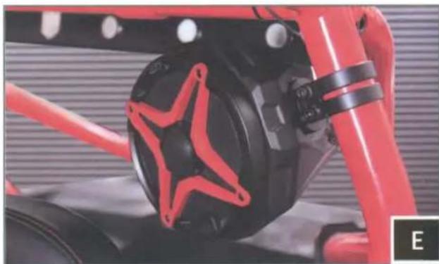
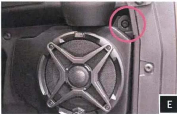
Close-up of a red and black mechanical component with a star-shaped emblem, no visible text or symbols.E. Route the speaker wire away from any moving parts and any sharp metal, then connect to the amplifier.
Connecting the US2-C65 using the pre-installed, two-pin connector will require an optional SSV Works plug-&-play harness (WP-H1149 - sold separately). If you are not using the WP-H1149 harness, simply cut off the two-pin connector and follow the wiring instruction below.
WIRING INSTRUCTIONS
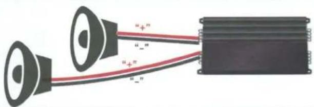
For proper sound, ensure the speaker polarity is correct connect the "+" to the "+" and the "-"to the "-"from the speaker wire to the amplifier. If using with an SSV Works complete system refer to the amplifier wiring instructions for more detailed wiring information.
text_image
"+"" "+" "+" "+"WARRANTY INFORMATION:
All SSV Works enclosures are covered by a limited lifetime warranty against defects in material or workmanship. All SSV Works Electronics are covered by a limited 1 year warranty against defects in material or workmanship. All Kicker Speakers are covered by a limited 1 year warranty against defects in material or workmanship. All Kicker Amplifiers are covered by a limited 2 year warranty against defects in material or workmanship. Labor for replacement of defective components is not covered. Contact SSV Works for further warranty information.

Please read and understand these instructions completely before installation to avoid possible injury, or damage to the accessory or vehicle.
TOOLS NEEDED FOR INSTALLATION
-T-40/30/25 Torx Driver - Phillips Screwdriver - Drill - 3/32" Bit - 9/16" Bit - Uni-Bit
PARTS LIST IMAGES
natural_image
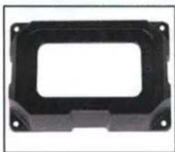
Black plastic enclosure with mounting holes and a rectangular cutout (no text or symbols)- MRB3 Dash Kit

text_image
17.0000 17.0000- MRB3 Controller
natural_image
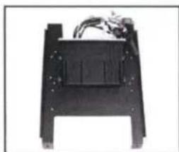
Black mechanical component with mounting holes and wiring (no visible text or symbols)- Mounting Plate with MRB3 Brain and Amps

natural_image
Close-up of a black screw with threaded shaft (no text or symbols visible)- MRB3 Controller/Dash Screws x6
natural_image
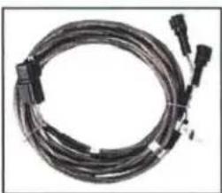
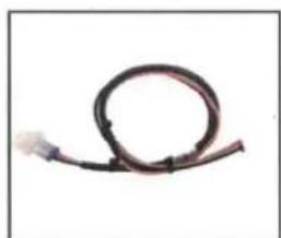
Coiled black cable or connector with multiple connectors (no visible text or symbols)- Front B-H1149 Speaker Harness
natural_image
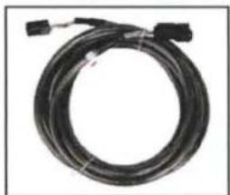
Coiled black cable with connectors, no visible text or symbols- Rear B-H1151 Speaker Expansion
natural_image
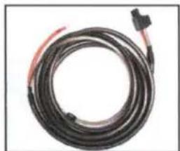
Coiled black cable with red connectors, no visible text or symbols- Amp Power Wire

natural_image
Close-up of a black plastic electronic component with a red internal structure and mounting holes (no visible text or symbols)- Fuse Holder with 40A Fuse x2
natural_image
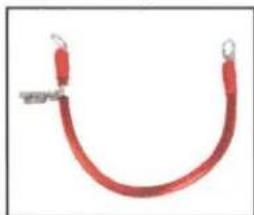
Red curved cable or wire with metal clamps, no visible text or symbols- Battery Terminal Cable x2
natural_image
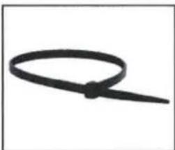
Simple black cable or wire loop on white background (no text or symbols)- Zip Ties

natural_image
Coiled black cable with red and blue bands, no visible text or symbols- USB/AUX Input Port
natural_image
Coiled black cable or wire against white background (no text or symbols)- B-H1221 MRB3 Power & Ground Connector

natural_image
Coiled electrical connector with black and red wires (no visible text or symbols)- 3-Pin T-harness BO-SS-HPGAT
natural_image
Coiled black cable with a red connector, isolated on white background (no text or symbols)- Antenna

text_image
SSV WORKS MAKE'S GNE NOISEA. Remove hood by turning locking pins and lifting up.

natural_image
Top-down view of a red vehicle chassis with mechanical components and highlighted circular features (no visible text or symbols)B. Use a panel tool to extract push pins circled in pink.

natural_image
Close-up of hands using a tool to clean or store items on a dark surface (no visible text or symbols)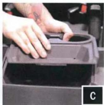
natural_image
Close-up of hands pressing a circular object into a dark container (no visible text or symbols)C. With push pins extracted, lift to remove the cup holder.

natural_image
Close-up of hands installing or adjusting a black mechanical component on a device (no visible text or symbols)D. Lift and disconnect gauge cluster for removal.
natural_image
Close-up of a metallic mechanical component with internal structural details (no visible text or symbols)E. Unscrew (4) torx screws located in upper glove box and remove box.
natural_image
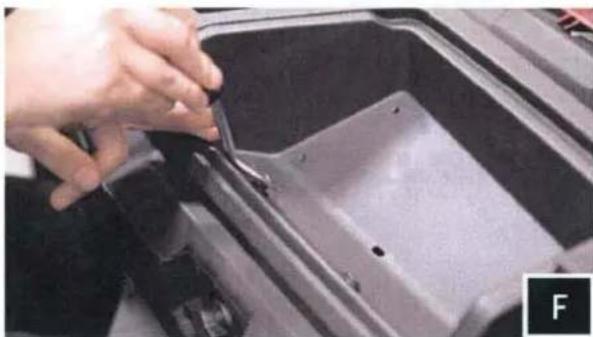
Close-up of a hand using a tool to cut or repair a dark metal container (no visible text or symbols)F. Extract push pins that are now exposed from removing the upper glove box.
natural_image
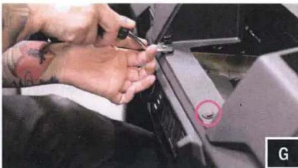
Close-up of hands using a screwdriver to adjust or repair a mechanical component, with a red circle highlighting a small hole (no visible text or symbols)G. Extract push pins exposed from cup holder removal.
natural_image
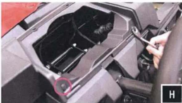
Close-up of a mechanical component with a hand adjusting parts, showing internal structure and a red circle highlighting a specific area (no visible text or symbols)H. Extract push pins exposed from gauge cluster removal.

natural_image
Close-up of a mechanical device interior with a tool interacting with a component (no visible text or symbols)I. Extract push pins located above driver and passenger side cup holders.
natural_image
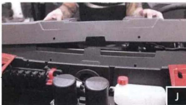
Close-up of a mechanical assembly with red components and a white bottle (no visible text or symbols)J. Lift to remove the dash.
natural_image
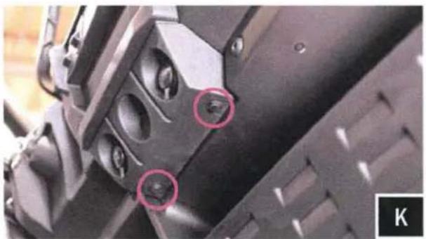
Close-up of mechanical components with two red-circled features, no visible text or symbolsK. Extract push pins located beneath 12v sockets.

natural_image
Close-up of a mechanical component with a highlighted circular area, no visible text or symbolsL. Remove front dash panel and disconnect the 12v socket harness.
natural_image
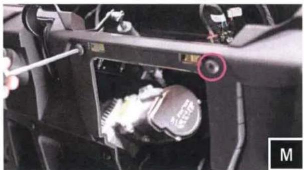
Close-up of a car engine bay with a wrench inserted, showing internal components and a highlighted valve (no text or symbols visible)M. Unscrew (2) torx screws that were behind the front dash panel.
natural_image
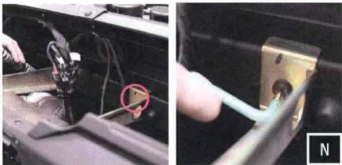
Two-panel image showing a hand inserting a cable into a mechanical component; no visible text or symbols.N. Unscrew the two (2) torx screws connecting the dash bracket at the rear of the dash cavity. Remove the under dash bracket. NOTE: IT WILL NOT BE RE-INSTALLED.
MRB3/AMP MOUNTING PLATE AND DASH CONTROLLER INSTALLATION
natural_image
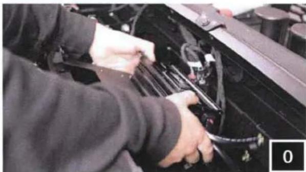
Person working on a car engine compartment with visible wiring and tools (no text or symbols)- Move the factory wiring to the rear of the dash cavity. Place the MRB3 mounting plate in the former location of the factory bracket.
natural_image
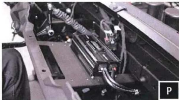
Close-up of a mechanical assembly with visible wiring and components (no text or symbols)P. With the MRB3 mounting plate set in place, check for any pinched wiring.

natural_image
Close-up of a car's engine component being adjusted for a tool, showing the lever and handle (no text or symbols visible)Q. Fasten down the plate with the factory hardware.
natural_image
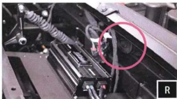
Close-up of a mechanical assembly with visible components and a circled area of interest (no text or symbols)R. Run amp power, and speaker extension cables out through the grommet that is fixed into the firewall (circled in pink). Be sure to run the correct end of the cable out through the firewall to avoid the inability to connect to the speakers.
S. With the cables now through the firewall, route them down the front of the machine to be full through the into the cabin of the machine. NOTE: A 1" hole may need to be drilled to run the cables down the front of the chassis.

natural_image
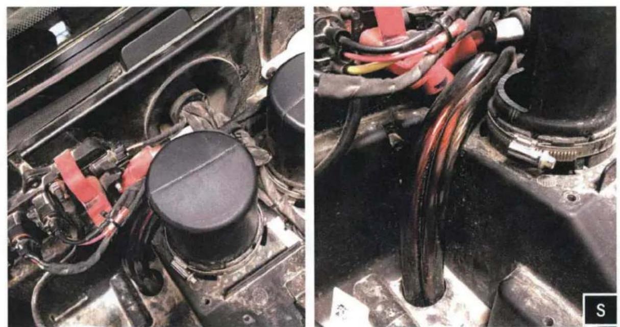
Close-up of a person working on an electric vehicle battery pack with wiring and cables (no visible text or symbols)T. Follow the air ducts and factory wiring and feed cables towards the battery compartment. (use provided zip ties to secure cables to factory wiring, away from the drive shaft).
natural_image
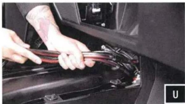
Close-up of hands installing or adjusting a car engine compartment with visible wiring (no text or symbols)U. Feed power/ground and (2) H1151 harness down towards the center console until you get the wires to the inside of the vehicle.

natural_image
Close-up of a mechanical assembly with visible components and wiring (no text or symbols)V. Route the H1149 harness towards the driver and passenger side of the dash. Secure the harness with zip ties away from any moving parts and any sharp metal.

natural_image
Close-up of hands installing or adjusting a plastic component with a rectangular opening (no visible text or symbols)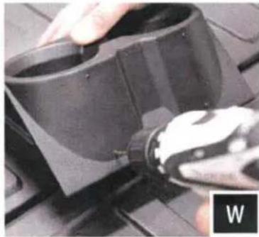
natural_image
Close-up of a hand using a power tool to adjust or install a black plastic component on a workbench (no visible text or symbols)W. Place MRB3 dash mount onto the center cup holder panel, and scribe the 4 corner mounting points. Make pilot holes using a 3/32" drill bit.
natural_image
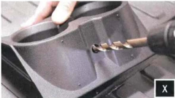
Close-up of a hand using a tool to cut a mechanical component, no visible text or symbolsX. Drill out the center of the cup holder for the controller cable to be routed through with a 9/16" drill bit. NOTE: Control drill bit depth to avoid puncturing through other side of cup holder.
natural_image
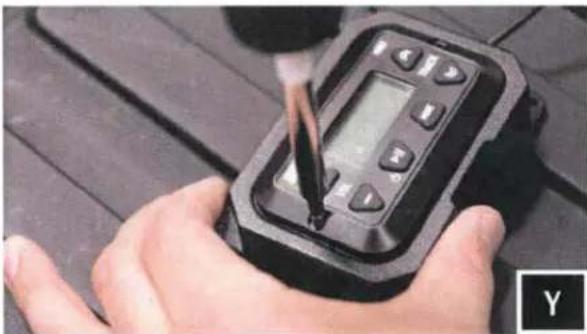
Close-up of a hand using a handheld digital device to test or inspect a component (no visible text or symbols)Y. Place MRB3 controller in controller mount and fasten down with provided screws.
natural_image
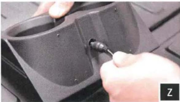
Close-up of hands using a screwdriver to adjust or install a black plastic component (no visible text or symbols)Z. Route MRB3 controller cable through cup holder

natural_image
Close-up of a hand using a tool to adjust or install a component, no visible text or symbolsA1. Fasten the dash mount to cup holder with provided screws.
natural_image
Close-up of hands holding a black cylindrical connector with visible pins, against a plain white background (no text or symbols)B2. Connect the antenna.
natural_image
Close-up of hands connecting a black cable to a white surface (no text or symbols visible)B2. Connect the MRB3 controller to the brain.

natural_image
Close-up of hands using a tool to cut or mark a small component, no visible text or symbolsB3. Connect the power/ground wire.
TOOLS NEEDED FOR INSTALLATION
- T-30 & T-40 Torx Driver - 4mm Allen Key - Panel Removal Tool - Drill - 13/64" Drill Bit
PARTS LIST IMAGES
natural_image
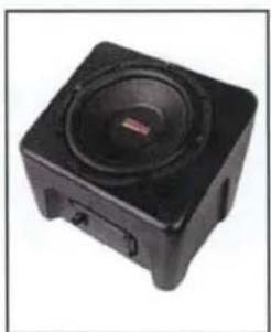
Black square electronic device with a speaker grille and control buttons (no visible text or symbols)- RG4-US10 Enclosures
natural_image
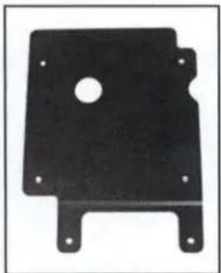
Black metal plate with a central hole and four mounting feet (no text or symbols visible)- Enclosure Bracket A
natural_image
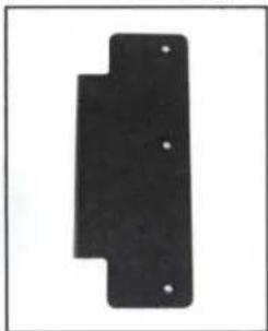
Black rectangular object with four small holes, no visible text or symbols- Enclosure Bracket B
natural_image
Close-up of a black screw with a flanged head and threaded shaft (no text or symbols visible)- M6 Flathead 4mm Hex Screws x4

natural_image
Close-up of a black threaded bolt (no text or symbols visible)- M6 Allen Torx Screws x2
natural_image
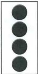
Three vertically aligned dark circular shapes on a white background (no text or symbols)- Foam Circles x4
NOTE: To avoid subwoofer damage, do not face the subwoofer down or rest the enclosure on the subwoofer when installing bracket to the bottom of the enclosure.
natural_image
Close-up of a hand holding a black electronic device with multiple circular features, no visible text or symbols.A. Align bracket A's holes with the dimples/recess' circled in pink on the bottom of the enclosure. Using four (4) flathead 4mm screws, mount the A bracket to the bottom of the enclosure. After the bracket is secure, cover the screw heads with the (4) foam circles.
natural_image
Close-up of a metal mechanical component with mounting holes and a hand holding a screwdriver (no visible text or symbols)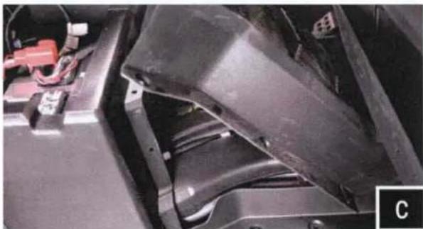
natural_image
Close-up of a black automotive component with visible wiring and mounting bracket (no text or symbols)C. Using a panel removal tool, extract the (8) push pins to remove the center driveline center column cover.
natural_image
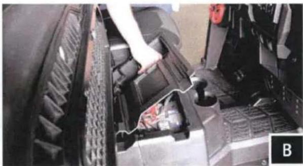
Close-up of a mechanical component with a hand adjusting a part, showing internal structure and no visible text or symbols.B. Flip up passenger seat and remove center tray to access battery. Disconnect the negative battery cable from the battery.
natural_image
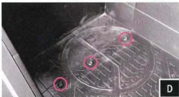
Close-up of a mechanical component with circular red markings and a textured surface (no visible text or symbols)D. Located on the floorboard to the right of the battery compartment, remove the (3) T40 torx screws circled in pink.
natural_image
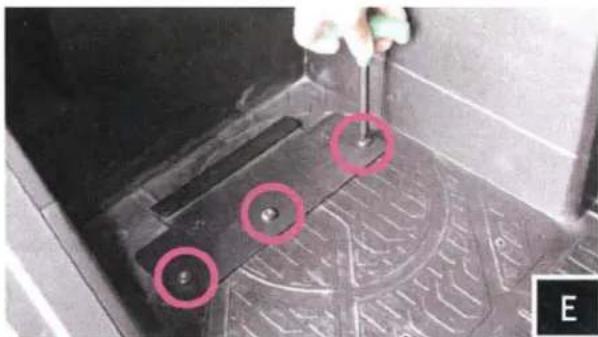
Close-up of a mechanical component with red circles highlighting features, no visible text or symbolsE. Place SSV bracket B over the factory screw holes and refasten down with the (3) factory T40 torx screws removed in the previous step.
natural_image
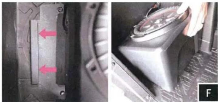
Close-up of a mechanical component with red arrows indicating features, alongside a close-up of a mechanical lever mechanism (no visible text or symbols)F. With the bracket secured to the floorboard, place the enclosure in front of the floorboard bracket. To allow proper engagement, tilt the enclosure back slightly and slide its bottom bracket into the floorboard bracket catch.
natural_image
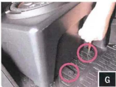
Close-up of a car intake manifold with a hand holding a tool, showing red circular annotations (no text or symbols)G. With the brackets seated into one another, use the front mounting tabs as a template to mark with a scribe or punch the needed placement to drill pilot holes.
natural_image
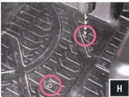
Close-up of a textured surface with two circled regions and a small object, no visible text or symbols.H. Once marked, remove the enclosure. Using a 13/64" drill bit, drill pilot holes at your marked points. Be sure to penetrate through the chassis lying beneath the floorboard.
natural_image
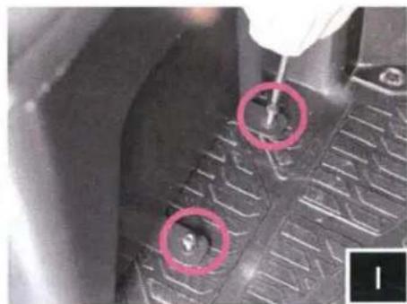
Close-up of a car tire tread pattern with two red-circled holes, no visible text or symbolsI. . Re-install the sub-enclosure. Secure the front mounting tabs with the kit provide T30 torx self-tapping screws.
natural_image
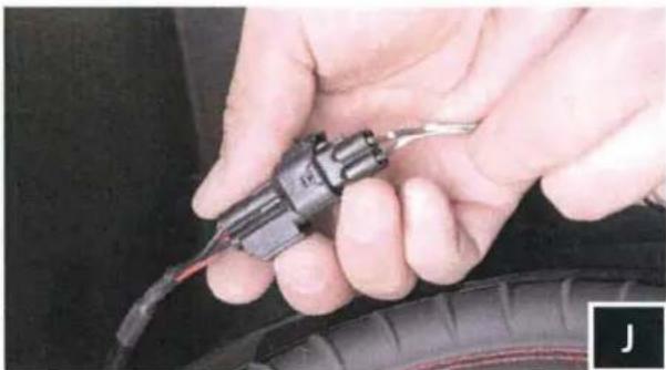
Close-up of hands holding a black automotive tire with a tool inserted (no visible text or symbols)J. Connect sub to harness B-H1151 from the battery compartment.
TOOLS NEEDED FOR INSTALLATION
- T-30 Torx Driver - Panel Removal Tool - Phillips Screwdriver
PARTS LIST IMAGES
natural_image
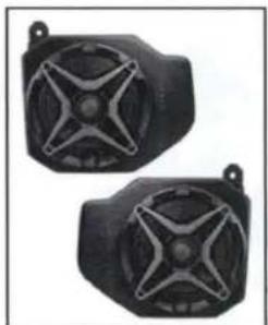
Two black industrial sensor or speaker modules with star-shaped cutouts, mounted on a stand (no visible text or symbols)- RG4-F65 Enclosures (1 pair)
natural_image
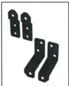
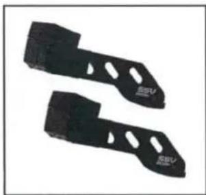
Four black metal bracket components with holes, arranged diagonally (no text or symbols visible)- Enclosure Brackets x 4

natural_image
Close-up of a black screw with threaded shaft (no text or symbols visible)- M6 x 16mm Screws x 10

natural_image
Simple black ring shape on white background (no text or symbols)- M6 Washers x 8 (small)

natural_image
Simple black circular ring shape on white background (no text or symbols)- M6 Washers x 2 (large)
natural_image
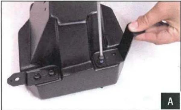
Close-up of a hand adjusting a black metal bracket with a tool, no visible text or symbolsA. Using the supplied M6 screws and small washers, install the brackets to kick pods.
natural_image
Close-up of a computer interface with a hand inserting a cable into a socket, highlighted by a pink circle (no text or symbols visible)C. Remove factory T25 torx screws located underneath the dash.
natural_image
Close-up of a mechanical component with a highlighted bolt and tool, no visible text or symbolsB. Remove factory T40 torx screws located from the front of the dash next to the cup holders.
natural_image
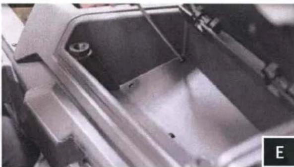
Close-up of a hand using a tool to adjust or install a black object on a car door (no visible text or symbols)D. Located on the inside top of the pocket you will have two holes, route speaker wire though the larger hole. The smaller hole will be used to mount the pod in Step P.
natural_image
Close-up of a mechanical component with a star-shaped knob and a red circle highlighting a specific feature (no text or symbols visible)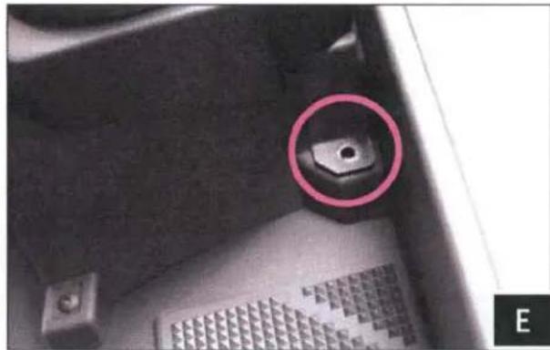
natural_image
Close-up of a mechanical component with a highlighted circular feature (no text or symbols visible)E. Place the speaker pod in location and resecure the factory screws through the pod brackets on the front and underneath the dash.

natural_image
Close-up of a mechanical component with a red circle highlighting a small feature, labeled F1 in corner (no readable text or symbols)
natural_image
Close-up of a black mechanical component with a red circular mark and a cable inserted, no visible text or symbols.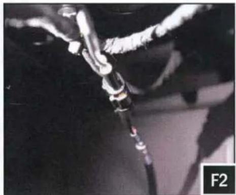
natural_image
Close-up of a mechanical component with wires and a black rod, labeled F2 in the corner (no readable text or symbols)P. From the inside-top of the dash, secure the top mounting M6 screw and large washer to the pod through the smaller hole next to the routed speaker wire (figure F1). Then connect the B-H1149 harness to the speaker cable coming out of the speaker pods (figure P2).
natural_image
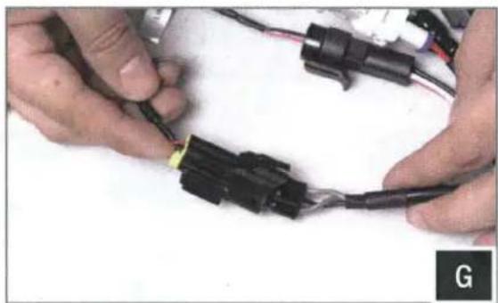
Close-up of hands connecting black plastic connectors with wires (no visible text or symbols)G. Connect the Line Out plug to the B-H1149 speaker harness.
TOOLS NEEDED FOR INSTALLATION
- 5mm Allen Key
- 3mm Allen Key
- 8mm Open End Wrench
- #2 Phillips Screwdriver
PARTS LIST IMAGES

natural_image
Two black mesh bags with curved handles, no text or symbols visible- US2-C65 Enclosures (1 pair)
natural_image
Two black metal cutting slots with circular holes, no text or symbols visible- Ranger Clamp x 4
natural_image
Close-up of a black plastic electrical connector with red and black wires (no visible text or symbols)- Aftermarket Speaker Adapter (comes with unloaded pods only)
natural_image
Two mechanical components: a circular nut and a hexagonal bolt (no text or symbols visible)- M6 Hex Head Bolts & Washers x4
natural_image
Mechanical component with threaded shaft and circular hole (no text or symbols)- M6 Allen Socket Head Bolts & Washers x4
natural_image
Abstract sketch of a vertical stack of papers or documents (no text or symbols)- M6 Set Screws x 8
natural_image
Close-up of a mechanical component with multiple holes and a central rod, labeled 'A' in the corner (no text or symbols on the object itself)A. Find the best orientation for the speaker on your bar and screw in the Set Screws in the OPPOSITE holes of where the clamp will install into.
natural_image
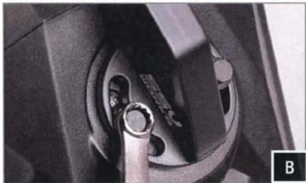
Close-up of a mechanical component with a metal ring inserted, showing internal structure (no visible text or symbols)B. Loosely install the clamp base to the cage mount pod with the two (2) M6 Hex head bolts and washers, place the cage mount pod in the desired mounting location and tighten the hex head bolts using a 8mm wrench.

natural_image
Close-up of a mechanical component with a black bracket and mounting holes (no visible text or symbols)C. Position the clamp underneath the rear crossbar

natural_image
Close-up of a hand adjusting a black plastic component (no visible text or symbols)D. Slide the top mount for the clamp into the top crossbar notch and line up screw holes.
natural_image
Close-up of a mechanical assembly with metal components and a black bracket (no visible text or symbols)E. Place screws in the clamp and use a 5mm hex driver to tighten the bracket

natural_image
Close-up of hands adjusting a small mechanical component against a black metal frame (no visible text or symbols)F. Route the speaker wire away from any moving parts and any sharp metal, then connect to the amplifier REAR OUTPUT
AUX/USB PORT INSTALLATION
natural_image
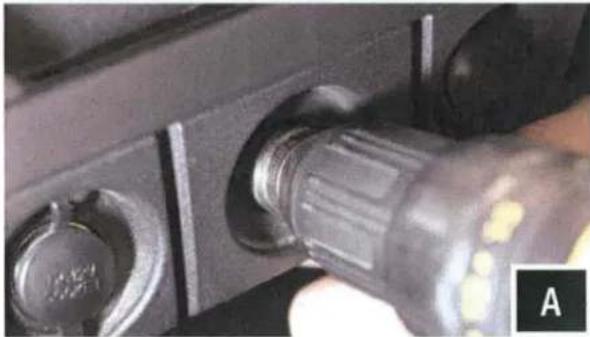
Close-up of a black USB flash drive with adjustment knob (no visible text or symbols)A. Using a Uni-bit, drill a 1" hole through the blank circular panel between the 12v ports.

natural_image
Close-up of hands adjusting a black plastic connector (no visible text or symbols)B. Unscrew and remove the plastic nut from the port. Make sure to open the fuse holder and remove the fuse so the nut will fit through it. Feed in the wires through the hole. Keep the fuse holder open and empty until it has passed through the hole.
natural_image
Close-up of a hand holding a black threaded component, possibly a valve or connector (no visible text or symbols)C. Feed the plastic nut back through the wires and cables and screw back on to the port. Hand tighten only. Re-insert the fuse and close the fuse holder.

natural_image
Close-up of hands assembling or connecting electrical connectors with wires (no visible text or symbols)D. Connect the Aux-in plug to the MRB3 brain.
CONNECTING POWER
natural_image
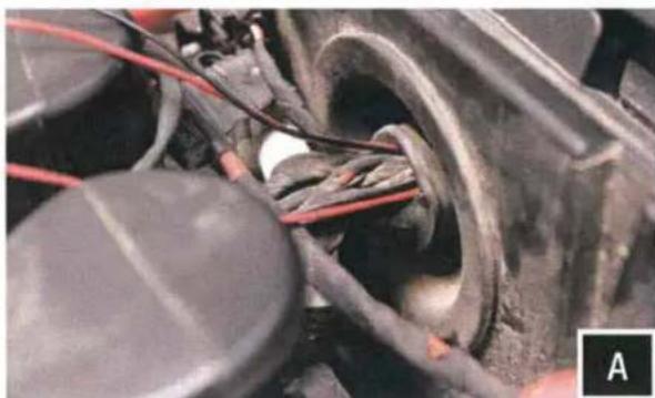
Close-up of a mechanical component with wires and a circular housing, no visible text or symbolsH. Feed the power and ground wires from the B-H1221 (MRB3 brain power) and the USB/AUX port through the grommet that passes through the firewall from under the dash to under the hood.
natural_image
Close-up of hands using a red power tool to wire a thin wire on a black surface, with wires and tools visible (no text or symbols)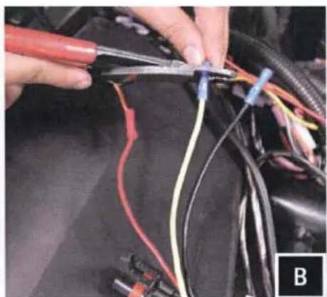
natural_image
Close-up of hands using pliers to connect wires with a car body (no visible text or symbols)
natural_image
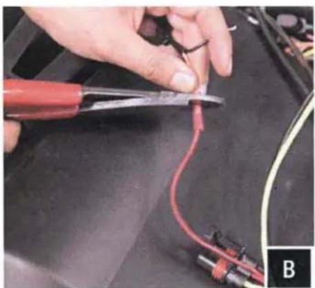
Close-up of hands connecting automotive wiring to a black engine compartment (no visible text or symbols)B. From the B-HPGAT Harness: use accessory red wire for power to USB/Aux adapter, use yellow wire for power to B-H1221 from the MRB3 brain, both grounds from USB/Aux adapter and B-H1221 crimp to black wire.
natural_image
Close-up of a mechanical component with wiring and a red circle highlighting a specific part (no visible text or symbols)C. Connect the HPGAT harness to an empty port on the factory buss bar located under the hood.
CONNECTING POWER & GROUND CABLE TO BATTERY
text_image
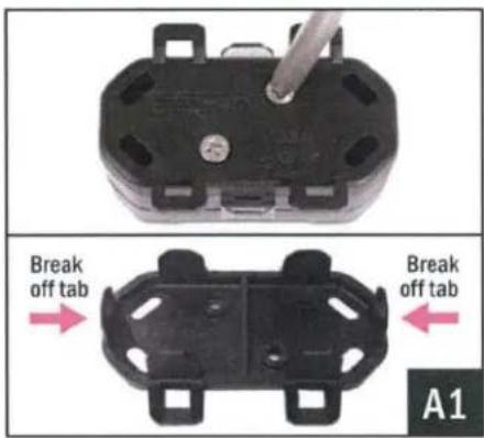
Break off tab Break off tab A1A1. Remove the bottom cover of the fuse holder by extracting the 2 screws. Break off the right and left side tabs on the bottom cover.

natural_image
Close-up of a black electronic component with two metallic pins and a metal screwdriver inserted (no visible text or symbols)A2. Extract both fuse holder screws.
text_image
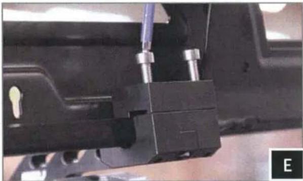
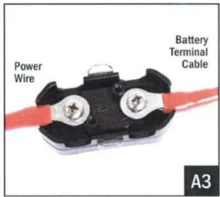
Power Wire Battery Terminal Cable A3A3. Attach both the Power Wire and Battery Terminal Cable to the fuse holder. Reattach the bottom cover.
natural_image
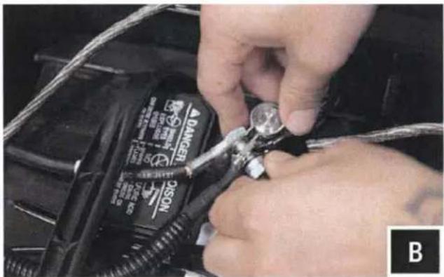
Close-up of hands using a tool to adjust or install a black DANCEO C-SCC battery component (no visible text or symbols)B. Unscrew the factory nut on the negative battery terminal. Install the 2 ground cables to the screw on the ground battery terminal. Re-install the factory nut.
natural_image
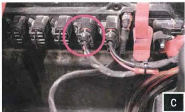
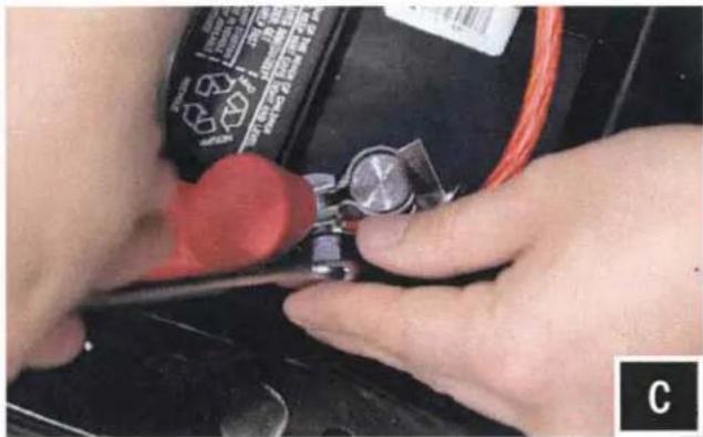
Close-up of hands using a tool to adjust or install a small component on a black surface, no visible text or symbols.C. Unscrew the factory nut on the positive battery terminal. Install the 2 power cables to the screw on the positive battery terminal. Re-install the factory nut.
natural_image
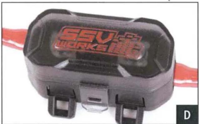
Close-up of a black workpiece labeled 'SSV WORKS' with red branding, attached to a red cable (no additional text or symbols visible)D. Remove the top of the fuse holder and extract the 2 screws. Insert the 40A fuse, screw the 2 screws back in and reattach the fuse holder top.
natural_image
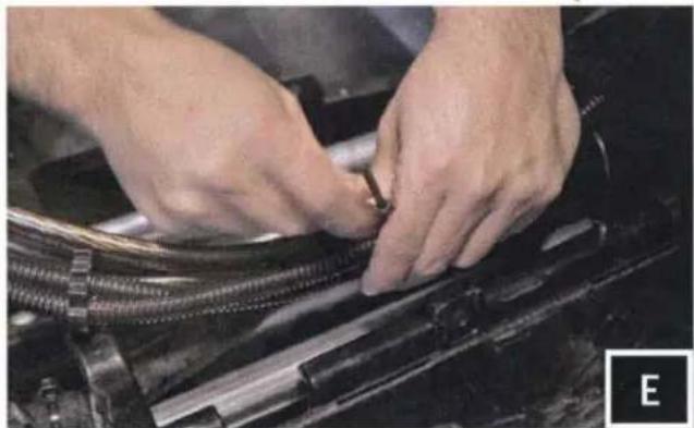
Close-up of hands assembling or adjusting a mechanical component with threaded parts (no visible text or symbols)E. Zip tie all of the electrical cabling (factory and audio) along the center column away from the drive shaft.
THIS CONCLUDES THE INSTALLATION PROCESS. REPLACE THE FACTORY PANELS AND SEATS. QUESTIONS? PLEASE CONTACT SSV WORKS AT 818-991-1778 OR EMAIL SUPPORT@SSVWORKS.COM