JIVA XT-2614Q - Cash register Posiflex - Free user manual and instructions
Find the device manual for free JIVA XT-2614Q Posiflex in PDF.

User questions about JIVA XT-2614Q Posiflex
0 question about this device. Answer the ones you know or ask your own.
Ask a new question about this device
Download the instructions for your Cash register in PDF format for free! Find your manual JIVA XT-2614Q - Posiflex and take your electronic device back in hand. On this page are published all the documents necessary for the use of your device. JIVA XT-2614Q by Posiflex.
USER MANUAL JIVA XT-2614Q Posiflex
natural_image
Illustration of a flat-screen monitor mounted on a stand (no text or symbols visible)Package Contents
√ Terminal with base stand.....x1
√ 60W power adaptor.....x1
√ Power cord.....x1
√ Screw for IO cable cover.....x2
√ User manual.....x1
√ Recovery or information CD.....x1
Product Features
Standard Features
System
Intel Bay Trail-D J1900 2.0G up to 2.42G, 2M Cache, 4 core
Mechanical Structure
● Fanless structure with Aluminum die-cast main unit casing
● Water resistant structure allowing easy cleaning
- Foldable base
Display
- High-quality 15” TFT active matrix LCD monitor provided with true-flat Projected Capacitive touch panel supporting 10-point multi-touch for 3815, with resistive touch panel for XT-3915, and with Infrared touch panel for XT-3915IR
Optional Items
System
● DDR3L SODIMM memory expansions up to 8GB (Max.) for XT-3815/3915/3915IR (J1900) in one SODIMM
- Preload Windows POSReady 7 / Win 7 / Windows Embedded 8.1 Industry / Linux per request
WIFI
● Wireless LAN module, through Mini PCI-E Interface
Connection Cable
● Parallel extension cable
● RJ50-to-DB9 serial port conversion cable
- Split cable for 2 cash drawer control
Base
- GEN 8E base including UPS battery and poweredUSB board, and supporting 60W/80W/150W power adaptor
Integration Kit
- Integrated side mount upgrade kits, such as SA-105 provided with optional MSR, SA-205 provided with iButton, SA-305, and SA-405
- 1" SATA SSD
● PoweredUSB kit in GEN 8E base stand, such as PU-480 or PU-490
● Power adapter kits for 80W/150W power adapters
● Back mount displays, such as LM/TM-3010/3014 and PD-6307
Views of the XT-3815/3915/3915IR
Front and Rear Views of Terminal with Gen 7E Base Stand

text_image
LCD Touch Panel Power Indicator Base Stand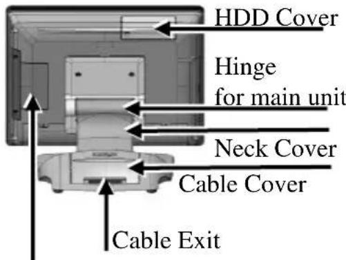
text_image
HDD Cover Hinge for main unit Neck Cover Cable Cover Cable ExitDDR3 Memory Cover
Left Side View of Terminal with Gen 7E Base Stand

text_image
Power Button Brightness Adj Button “+” Brightness Adj Button “-” USB 2.0 Port Locking HookBottom View of Terminal with GEN 7E Base Stand

text_image
Bottom Plate Rubber Cushion Wrapping ScrewFront and Rear Views of Terminal with GEN 8E Base Stand
text_image
LCD Touch Panel Power Indicator Base Stand HDD Cover Hinge for main unit Cable Cover Cable Exit Neck CoverDDR3 Memory Cover
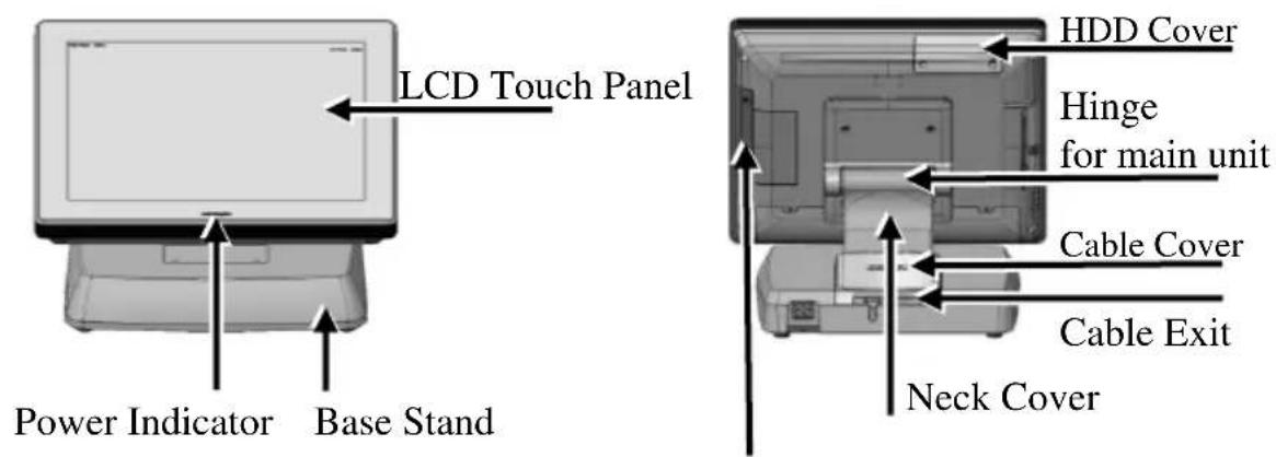
Left Side View of Terminal with GEN 8E Base Stand
text_image
Power Button Brightness Adjustment Button “+” Brightness Adjustment Button “-” USB 2.0 Port Locking HookBottom View of Terminal with GEN 8E Base Stand

text_image
Power Adaptor Chamber UPS Chamber Bottom Plate PoweredUSB Board Cover Rubber Cushion Wrapping ScrewViews of I/O Interfaces of Terminal

text_image
1 2 3 4 5 6 7 8 9 101 DC-IN Power Jack
2 UPS Port
3 CR Port
4 DB9 COM Port
5 RJ50 COM Port
6 VGA Port
7 LAN Port
8 USB 2.0 Port
9 USB 2.0 Port
10 USB 3.0 Port
Installing Power Adapter Kit onto GEN 8E Base Stand
The power adapter kit is optional and, before shipping, is installed onto the optional GEN 8E base stand. Upon your needs, you can purchase and install the kit for 80W or 150W power adapter. The introduction to the kit and the brief description of installation of the kit are made below.
For the detailed description of installation of the 80W/150W power adapter kit, refer to the XT-3815/3915/3915IR technical manual.
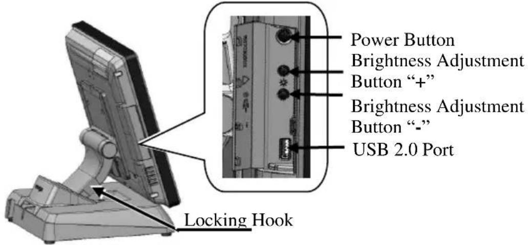
Secure the Power Cord
To avoid the power cord from being pulled out accidentally, the power adapter kits are shipped with a power cord bracket.

After installing the power adapter kit and connecting the power cord to the power adapter, remember to use the power cord
bracket to secure the power cord.
natural_image
Mechanical assembly diagram showing a shaft and housing with an arrow indicating motion direction (no text or symbols)

text_image
Fixing with screwConnecting Power Cable Connector to the Terminal
Before turning turn ON the terminal, connect the power cable connector to the power jack of the terminal.

natural_image
Back view of a computer monitor rear panel showing ports and connectors (no visible text or symbols)CAUTION:
Before connecting the power cable to the power jack of main unit, do NOT touch any metal pin of the connectors or circuits to avoid high voltage hazard or electrostatic discharge damage.
Powering ON the XT-3815/3915/3915IR
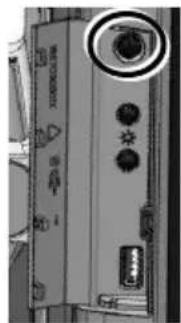
After connecting the power cable to the power jack of main unit, slightly push to open the power button cover at the left side of the main unit.

natural_image
Close-up of a handheld electronic device with a rectangular panel and cylindrical handle (no visible text or symbols)Then press the power button to power on the main unit. To power it off, press the button again.
natural_image
Close-up of a computer monitor with control buttons and a USB drive (no visible text or symbols)Once powering off the system, if you want to power it on again, please wait for at least 3 seconds.
If the system hangs due to a reason, such as software resource conflict, please press and hold the power button for 10 seconds around to forcedly shut down the system.
Power Indicator
There is a power LED indicator serving for several purposes located at the center of lower rim of LCD panel. The relationship between the indicator status and other conditions is summarized below:

| Indicator Status | System Status | External Power | UPS Battery | Powering Up |
| Off | Off | Off | Not present | Not possible |
| Off | Off | Off | Present | Not allowed |
| Green | Off | On | No influence | Allowed |
| Blue | On | On | No influence | N/A |
| Blue/Flash | On | Off | Activated | |
| Green/Rapid Flash | On | Off | Battery low |
Installing an Operating System
This product is highly professional equipment. Therefore, we do NOT encourage you to install any operating system into this machine. Posiflex Technology, Inc. shall not be responsible for any technical support to questions on this aspect. We suggest that you contact your dealer for OS installation.
Specifications
| XT-3815/3915/3915IR | |
| CPU | Intel Bay Trail-D J1900 2.0G up to 2.42G, 2M Cache, 4 core |
| Memory | DDR3L 1333 FSB, SO-DIMM socket *1, 8G (Max.) |
| OS | POSReady 7 / Win 7 / Windows Embedded 8.1 Industry / Linux per request |
| Display | XT-3815:15-inch TFT LCD monitor (1024x768) with true-flat pc touch panelXT-3915:15-inch TFT LCD monitor (1024x768) with resistive touch panelXT-3915IR:15-inch TFT LCD monitor (1024x768) with infrared touch panel |
| Storage | SATA storage x 2 (one for 2.5” HDD/SSD and the other for 1” SSD only), or optional eMMC module x 1 |
| Ethernet | 10/100/1000 Mb x 1 port |
| WLAN | Optional, through mini PCI-E interface |
| Power Supply | 12 VDC power adaptor, 60W / optional UPS battery (2300mAh/12V) |
| Serial port | RJ-45 X 1, DB9 X 3, RJ-50-to-DB9 cable (Optional) |
| Parallel port | proprietary port connector in jumper setting window(by specially optional conversion cable) |
| CR Port | 1 port, available for controlling 2 CR. |
| USB Port | Standard, 6 ports on the I/O plate (USB 2.0 X 5, USB3.0 X 1), 1 port on the left side (USB2.0), 3 USB headers reserved for internal USB device use |
| PS/2 KB Port | Pin header on back window |
| Audio | Built-in 2W audio speaker |
| Extension slot | Mini PCI-E slot, with USB signal |
| Power-Off Control | Hardware button or by software control |
| Power Switch | Soft switch |
| Power-ON Wake-Up | Through alarm or LAN |
| Mechanical installation | Desktop or wall mount |
| Power LED Indicator | Power ON/ standby, bi-color LED indicators |
| Temp & Humidity | Operation Temp.: 0 to 40 °C / Storage Temp.: 20 to 85°CHumidity: 10 to 90 %; 5 to 90 % (operation condition) |
※ The product information and specification are subject to change without prior notice. To get the detailed information on XT-3815/3915/3915IR, please check this model from Posiflex Global Website (http://www.posiflex.com/en-global/Download/download).