RT-6015Q-G2 - Cash register Posiflex - Free user manual and instructions
Find the device manual for free RT-6015Q-G2 Posiflex in PDF.

User questions about RT-6015Q-G2 Posiflex
0 question about this device. Answer the ones you know or ask your own.
Ask a new question about this device
Download the instructions for your Cash register in PDF format for free! Find your manual RT-6015Q-G2 - Posiflex and take your electronic device back in hand. On this page are published all the documents necessary for the use of your device. RT-6015Q-G2 by Posiflex.
USER MANUAL RT-6015Q-G2 Posiflex
This equipment has been tested and found to comply with the limits for a Class A digital device, pursuant to part 15 of the FCC Rules. These limits are designed to provide reasonable protection against harmful interference when the equipment is operated in a commercial environment. This equipment generates, uses, and can radiate radio frequency energy and, if not installed and used in accordance with the instruction manual, may cause harmful interference to radio communications. Operation of this equipment in a residential area is likely to cause harmful interference in which case the user will be required to correct the interference at his own expense.
This device complies with part 15 of the FCC Rules. Operation is subject to the following two conditions: (1) This device may not cause harmful interference, and (2) this device must accept any interference received, including interference that may cause undesired operation.
CE CLASS A WARNING
This equipment is compliant with Class A of CISPR 32. In a residential environment this equipment may cause radio interference.
AVERTISSEMENT CE CLASSE A
Warranty will terminate automatically when the machine is opened by any person other than the authorized technicians. The user should consult his/her dealer for the problem happening. Warranty voids if the user does not follow the instructions in application of this merchandise. The manufacturer is by no means responsible for any damage or hazard caused by improper application.
LIMITES DE GARANTIE
This equipment is not suitable for use in locations where children are likely to be present.
CONSIGNES DE SÉCURITÉ
Power cord shall be connected to a socket-outlet with earthing connection.
ATTENTION
Risk of explosion if battery is replaced by an incorrect type. Dispose of expended battery in accordance with local disposal regulations.
AVERTISSEMENT DE BATTERIE
| Date | Version | Description |
| 2024/02/26 | A0 | For Preliminary Release |
| 2024/05/27 | B0 | The mechanical part has modified the neck cover, back cover and base to improve the inconvenience that consumers may encounter when using it. |
Package Contents
√ RT-6015-G2/RT-6015Q-G2 15" fanless touch terminal or RT-6016-G2/RT-6016Q-G2 15.6" fanless touch terminal....(x1)
√ Power adapter....(x1)
√ Power cord....(x1)
Views of RT-6015-G2/RT-6016-G2
Front View

flowchart
graph TD
    A["Camera (Optional)"] --> B["PTC"]
    B --> C["LED indicator 15" RT-6015-G2"]
    B --> D["Base Stand"]
    E["PTC"] --> F["LED indicator"]
    G["PTC"] --> H["LED indicator"]
    I["PTC"] --> J["LED indicator"]
    K["PTC"] --> L["PTC"]
    M["PTC"] --> N["PTC"]
    O["PTC"] --> P["PTC"]
    Q["PTC"] --> R["PTC"]
    S["PTC"] --> T["PTC"]
    U["PTC"] --> V["PTC"]
    W["PTC"] --> X["PTC"]
    Y["PTC"] --> Z["PTC"]
    AA["PTC"] --> AB["PTC"]
    AC["PTC"] --> AD["PTC"]
    AE["PTC"] --> AF["PTC"]
    AG["PTC"] --> AH["PTC"]
    AI["PTC"] --> AJ["PTC"]
    AK["PTC"] --> AL["PTC"]
    AM["PTC"] --> AN["PTC"]
    AO["PTC"] --> AP["PTC"]
    AQ["PTC"] --> AR["PTC"]
    AS["PTC"] --> AT["PTC"]
    AU["PTC"] --> AV["PTC"]
    AW["PTC"] --> AX["PTC"]
    AY["PTC"] --> AZ["PTC"]
    BA["PTC"] --> BB["PTC"]
    BC["PTC"] --> BD["PTC"]
    BE["PTC"] --> BF["PTC"]
    BG["PTC"] --> BH["PTC"]
    BI["PTC"] --> BJ["PTC"]
    BK["PTC"] --> BL["PTC"]
    BM["PTC"] --> BN["PTC"]
    BO["PTC"] --> BP["PTC"]
    BZ["PTC"] --> CA["PTC"]
    CB["PTC"] --> CD["PTC"]
    CE["PTC"] --> CF["PTC"]
    CG["PTC"] --> CH["PTC"]
    CI["PTC"] --> CJ["PTC"]
    CK["PTC"] --> CL["PTC"]
    CM["PTC"] --> CN["PTC"]
    CO["PTC"] --> CP["PTC"]
    CS["PTC"] --> CT["PTC"]
    CU["PTC"] --> CV["PTC"]
    DD["PTC"] --> DV["PTC"]
    DW["PTC"] --> DX["PTC"]
    DX --> DW
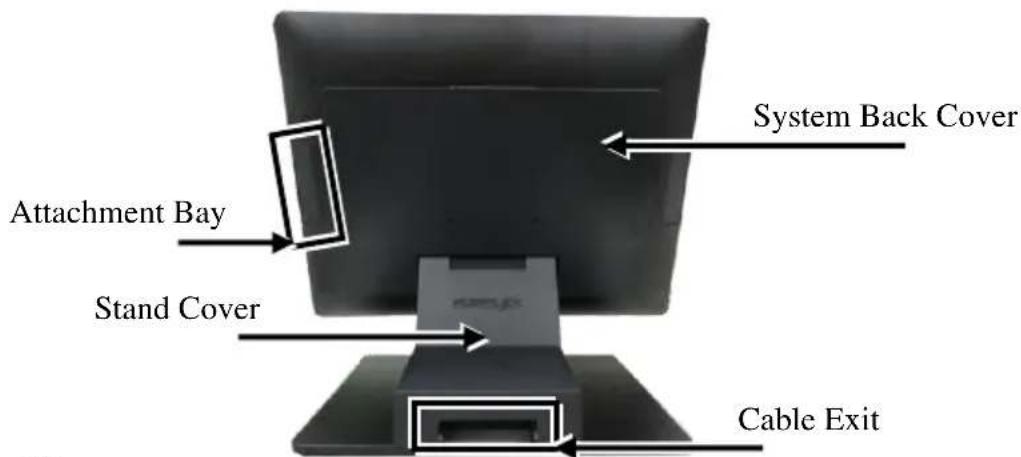
Rear View
text_image
System Back Cover Attachment Bay Stand Cover Cable ExitBottom View
text_image
Screw for Fire-Resistant System Back CoverRelease Lever for System Back Cover
Left-Side View

text_image
Power Button Brightness Adjustment Button + Brightness Adjustment Button -Views of RB-5000 UPS Base Stand
(Option for RT-6xxx-G2 Model, NOT for RT-6xxxQ-G2 Model)
Top View Bottom View

text_image
Through Hole Screw Hole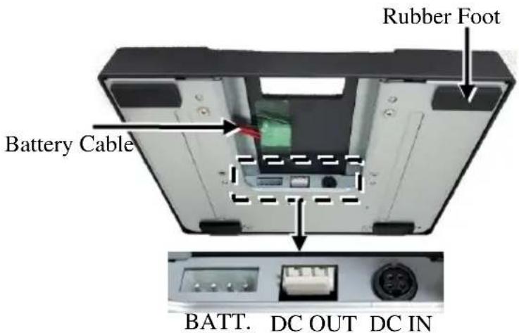
text_image
Rubber Foot Battery Cable BATT. DC OUT DC IN
When the AC power is turned off, the RT terminal will begin to be powered by the UPS battery and the RB-5000 will beep once every three seconds. At this time, back up the data on the terminal immediately and power off the RT terminal.

When the AC power is turned off, if the UPS battery is very low, the RB-5000 will beep once every second. At this moment, power off the RT terminal immediately.
To get more detailed information of RB-5000, please contact the service team of Posiflex or download the RB-5000 user manual from Posiflex Global
Website: (https://download.posiflex.com/en-
global/Download/index/manualUinstall_guide/pos-terminal/RT-6015-G2).
Views of RT-6015Q-G2/RT-6016Q-G2
Front View

flowchart
graph TD
    A["Computer monitor"] -->|Camera (Optional)| B["Computer monitor"]
    B -->|P-Cap Touch Panel| A
    A --> C["LED indicator"]
    B --> C
    A --> D["Image icon"]
    B --> E["Image icon"]
LED indicator
15" RT-6015Q-G2
15.6" RT-6016Q-G2
Rear View
Thumbscrew for VESA Mount Bracket

text_image
Attachment Bay System Back Cover Pole Mount Screw Hole
text_image
Bottom View Screw HoleRelease Lever for System Back Cover
Right-Side View

text_image
Power Button Brightness Adjustment Button + Brightness Adjustment Button -View of I/O Interface of RT-6xxx-G2/6xxxQ-G2
RT-6015-G2/RT-6016-G2
Bottom Side View

text_image
DB9 COM Port CR Port USB 3.0 Ports LAN Port RJ50 COM Ports Mini DisplayPort USB 2.0 Ports DC IN Power Connector PT-6015Q-C2/PT-6016Q-C2RT-6015Q-G2/RT-6016Q-G2
Bottom Side View

text_image
DB9 COM Port CR Port USB 3.0 Ports LAN Port RJ50 COM Ports Mini DisplayPort 24V PoweredUSB Port DC IN Power ConnectorLeft Side View
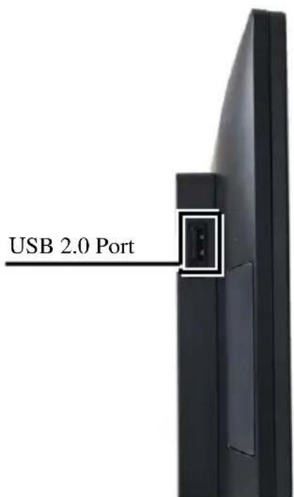
text_image
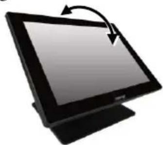
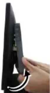
USB 2.0 PortPositioning your POS for a Perfect Viewing Angle
Steady the base with one hand, and then tilt the screen in the direction shown by the arrow in the figure. Please do NOT press on the LCD panel while setting up the tilt angle.
natural_image
Illustration of a computer monitor with an arrow indicating rotation (no text or symbols)Installing Power Adapter and Cables for RT-6xxx-G2
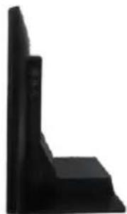
The following provides instructions required to install your cables.
- Lay the terminal with its rear facing towards you and tilt the screen all the way down.
natural_image
Black L-shaped object with stepped edges, no visible text or symbols- Remove the system back cover.
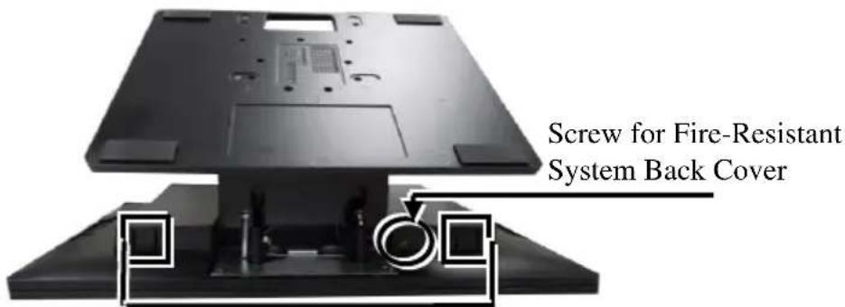
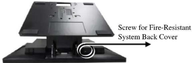
2.1 If the system back cover is fire-resistant, first locate the screw as indicated in the figure, and then remove it.
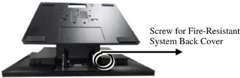
text_image
Screw for Fire-Resistant System Back Cover2.2 Hold down the release lever at the bottom of the system back cover and then pulling the cover outwards.

natural_image
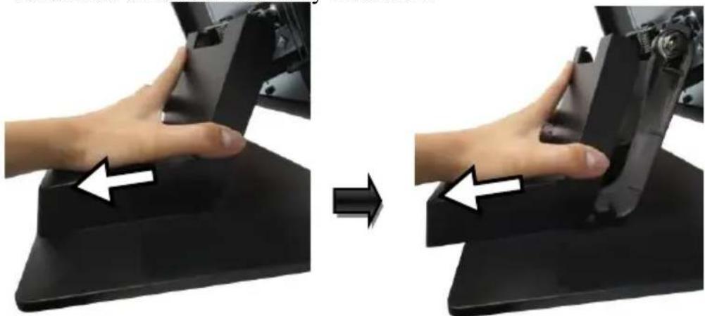
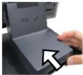
Close-up of a hand holding a black electronic device with a scroll wheel (no visible text or symbols)- To remove the stand cover from the base, please slide it in the horizontal direction shown by the arrow.
natural_image
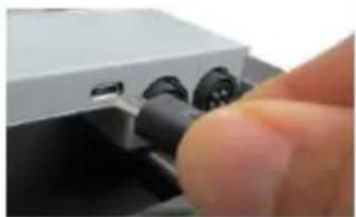
Two-step diagram showing hand positioning on a black ergonomic device, with arrows indicating left and right movement (no text or symbols)- Connect the connector of the power adapter to the DC-IN power jack. If necessary, properly insert other cables into the correct port.

natural_image
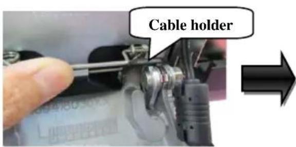
Close-up of a finger pressing down on a mechanical component (no visible text or symbols)- Neatly arrange the cables. Locate the cable holder inside the base as shown in the figure. Push down the lever to release if from the hook, pass the cable through cable holder, and then press down the lever again to lock it onto the hook.
text_image
Cable holder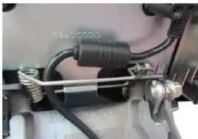
natural_image
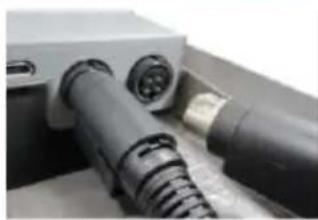
Close-up of mechanical components with hoses and connectors (no visible text or symbols)- Make sure the cord can be held into place and passed through the cable exit after sliding back the stand cover.
natural_image
Close-up of a hand pressing down on a laptop keyboard, with a white arrow pointing to the button (no visible text or symbols)7.
7.1 Place back the sytem back cover. Make sure it is well locked into place with a click sound.

natural_image
Close-up of a hand pressing down on a computer monitor (no visible text or symbols)7.2 For the fire-resistant system back cover, please insert another screw into the screw hole indicated in the figure, and secure it.

text_image
Screw f SystemScrew for Fire-Resistant System Back Cover
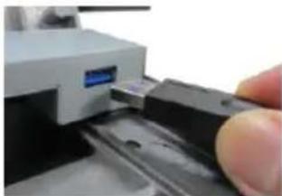
- Make sure the cable could be pulled out of the cable exit from the bottom of the base.
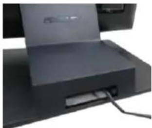
natural_image
Close-up of a computer monitor with a cable inserted, showing no visible text or symbolsInstalling Power Adapter and Cables for RT-6xxxQ-G2
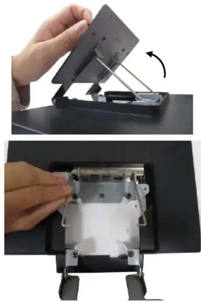
- There are two thumbscrews on the VESA mount bracket. Loosen the two thumbscrews.

natural_image
Top-down view of a black rectangular device with two circular ports and mounting brackets (no text or symbols visible)- Open the VESA mount bracket, and make the bracket separate from the two metal sticks.
natural_image
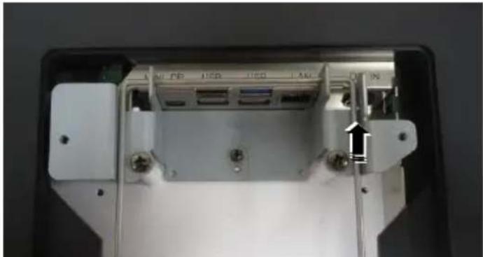
Two-step diagram showing a hand holding a flat panel and rotating its component, with no visible text or symbols.- Connect the connector of the power adapter to the DC-IN power jack. If necessary, properly insert other cables into the correct port.
natural_image
Close-up of a white electronic device rear panel showing ports and connectors (no visible text or symbols)- Close the VESA mount bracket, and then fasten the two thumbscrews.
Cable connectors like the connector of LAN cable have to be gently inserted until a click sound is given. It is recommended that the I/O ports, such as COM (DB9) port and VGA port, should be fastened with connector thumb screws after the I/O cable connectors are completely connected. And please make sure that each connector has to be connected to the right peripheral device in the right way.
CAUTION: On doing insertion or extraction of a cable connector, please always hold the connector head itself instead of pulling the cable wire. Doing this could damage the cables, which is considered as an artificial damage and is not covered by the warranty. The means of power cord should be connected to a socket-outlet with earthing connection.
Installing Optional Upgrade Kits and Peripherals
RT-6xxx-G2/6xxxQ-G2 is an expandable model which allows you to upgrade its own capacity by additionally installing multiple peripheral devices, such as magnetic stripe reader (MSR), fingerprint or iButton sensors, and 2^nd rear-mount POS monitor, according to your preference. The following will give you brief instructions on how to expand on your current POS system with these optional upgrade kits. Before proceeding with the installation of peripherals, please make sure the POS system is completely shut down to prevent damage.
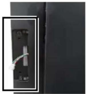
Installing Side Mount Upgrade Kits
Located at left side on the back of your system unit, side mount compartment is mainly used for installation of side-mounted equipment, such as magnetic stripe reader. For detailed installation instructions, please refer to the user manual specific to the device which you intend to mount onto the terminal.
natural_image
Close-up of a black electronic device with a cable inserted, showing internal components (no visible text or symbols)Installing Rear-Mount POS Monitor
RT-series POS terminal also allows you to additionally install rear-mount POS monitor to expand its functionality. Regarding the step-by-step instructions which aim to help you mount it onto your POS system, Please refer to the user manual specific to the device you intend to install.

natural_image
Close-up of a small electronic component enclosed in a rectangular frame (no visible text or symbols)Installing PoweredUSB or USB Hub for RT-6xxx-G2
Please go through the below steps to complete the installation of PoweredUSB or USB hub.
- After tilting the screen all the way down, remove the system back cover.
1.1 If the system back cover is fire-resistant, first locate the screw as indicated in the figure, and then remove it.
text_image
Screw for Fire-Resistant System Back Cover1.2 Hold down the release lever at the bottom of the system back cover and then pulling the cover outwards
natural_image
Close-up of a hand holding a black electronic device with a scroll wheel, showing a curved arrow indicating rotation (no text or symbols visible)- To remove the stand cover from the base, please slide it in the horizontal direction shown by the arrow.

natural_image
Two-step illustration showing a hand pressing down on a black electronic device, with arrows indicating the process (no text or symbols present)- Align the two screw bolts at the bottom of PoweredUSB or USB hub with rail slots in the base.

natural_image
Close-up of a computer interface showing a hand inserting two ports into a device, with no visible text or symbols.4.
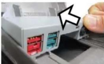
Push PoweredUSB or USB hub in the direction shown by the arrow to lock it into place.
natural_image
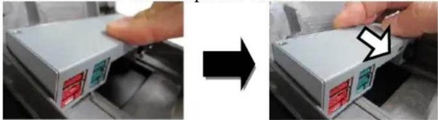
Close-up of a white electronic device with two red and blue connectors, showing a finger pointing to a button (no text or symbols visible)To remove the PoweredUSB or USB hub from the rail slots, press down the hubs first and then push it outwards.
natural_image
Two-step photo showing a hand pressing a device into a container, with a black arrow pointing to the next step (no text or symbols visible)- Install power adaptor extension cable, USB cable, and power adaptor for PoweredUSB hub.
5.1 Insert one end of the provided power adaptor extension cable to DC Input port of PoweredUSB hub and another end to DC-in power jack of the terminal.
natural_image
Close-up of a hand inserting a USB into a device housing (no visible text or symbols)5.2 Insert mini-USB connector of the USB cable to PoweredUSB hub and another end to USB3.0 port of the terminal.
natural_image
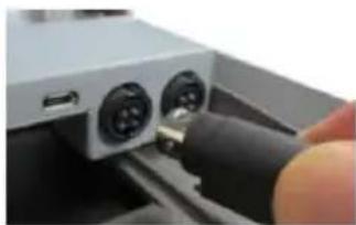
Close-up of a finger pressing down on a white electronic device with black connectors (no visible text or symbols)5.3 Connect the connector of the power adapter to DC Output port of PoweredUSB hub, and the other end to the electrical outlet.
natural_image
Close-up of a black electrical plug connector with a metallic connector (no visible text or symbols)- To Install USB cable for USB hub, Plug Type-A connector of USB cable to USB Port of USB hub and the other end of USB cable to USB3.0 port of the POS terminal.
natural_image
Close-up of a hand pressing a button on a mechanical device (no visible text or symbols)- Neatly arrange your cable and then slide back the stand cover.

natural_image
Close-up of a hand pressing down on a flat electronic device (no visible text or symbols)- .
8.1 Place back the sytem back cover. Make sure it is well locked into place with a click sound

natural_image
Close-up of hands holding a black monitor with a scroll wheel, showing a curved arrow indicating rotation (no text or symbols visible)8.2 For the fire-resistant system back cover, please insert another screw into the screw hole indicated in the figure, and secure it.

text_image
Screw for Fire-Resistant System Back CoverStatus LED Indicator
LED status indicator, which is located at the bottom edge of the LCD panel, is mainly responsible for notifying users of the current system status by emitting various LED signals. In the chart provided below, it describes all the possible LED status as a quick reference.
15" 6015-G2/6015Q-G2
| LED Status | Description |
| Off | System power OFF |
| Green | System standby |
| Blue | System power ON |
15.6" RT-6016-G2/6016Q-G2
| LED Status | Description |
| Off | System power OFF |
| Orange | System standby |
| Blue | System power ON |
Powering ON/OFF RT-6xxx-G2/6xxxQ-G2
Power ON RT-6xxx-G2/6xxxQ-G2
Press down the power button to power on the POS.
Power OFF RT-6xxx-G2/6xxxQ-G2
In most cases, press the power button of the POS to power the system off. If the terminal fails to turn off the machine for unknown reasons, please be advised to hold the power button more than 10 seconds to force a shutdown of the system.

text_image
Power ButtonInstalling an Operating System
You are highly advised not to install an operating system on RT-6xxx-G2/6xxxQ-G2 without professional instructions. Improper installation could lead to system malfunction or failure. Please contact with your dealers about the issues of operating system installation.
Driver Download
If your POS terminal is shipped without OS pre-installed, please download the relevant driver that you need from the Posiflex website (https://download.posiflex.com/en-global/Download/index/driver/post-terminal/RT-6015-G2).
Performing System Recovery
For RT-6xxx-G2/6xxxQ-G2 model with preloaded operating systems, Recovery DVD which includes useful utilities will be provided in the package to assist you in efficiently restoring or repairing your damaged system. However, you are not encouraged to recover your system without the help of system integrators. Please be advised to contact your service center for further assistance with system recovery.
Operation Environment
To prevent RT-6xxx-G2/6xxxQ-G2 from overheating, it is suggested to position your terminal in a well-ventilated working environment. In doing so, please be advised to keep the POS terminal at least 25mm away from other devices to ensure the machine is properly cooled down and functioning normally.
Specifications
| RT-6015-G2RT-6016-G2 | RT-6015Q-G2RT-6016Q-G2 | |
| CPU | Intel Tiger Lake Core i3 (default) /i5/i7 CPU | |
| System Memory | 2 x DDR4 SO-DIMM | |
| Storage Device | 2 x M.2 2280 | |
| OS Support | Windows 10 IoT | |
| vPro | Supported by Intel Tiger Lake Core i5/i7 CPU | |
| TPM | Yes, TPM2.0 (Intel PTT) | |
| RAID | Yes | |
| Power Supply | 12V/60W,can be upgraded to150W while adoptingPoweredUSB modulein the base | 12V/150W |
| LCD Panel | 15" 1024x768 TFT LCD with LED backlight15.6" 1920x1080 TFT LCD with LED backlight | |
| Touch Sensor | P-CAP touch | |
| Serial Port | 3 ports, DB9 x 1+ RJ-50 x 2 | |
| USB Port | 5 ports, USB3.0 x 2 +USB2.0 x 3 (2 on I/Oplate, 1 on left side) | 3 ports, USB3.0 x 2 +USB2.0 x 1 (on left side) |
| PoweredUSB | N/A | 24V PoweredUSB x 1 |
| LAN Port | 10/100/1000 Mb x 1 | |
| Display Port | eDP connector (internal header, support 15"and 15.6" LCD panel)VGA + USB + 12V (internal header,supporting 2nd monitor)1 x Mini DP port (on I/O plate) | |
| CR Port | 1 port, controlling 2 CR | |
| Audio Port | 1 x Internal 2W speaker | |
| Extension Slot | 1 x M.2 2230 slot for WiFi/BT module | |
| Mechanical | With base stand | No base, intended for wallmount/pole mount |
| Dimension(W x V x D in mm) | RT-6015-G2: 368 x 325 x 207RT-6015Q-G2: 368 x 292 x 46.6RT-6016-G2: 402 x 297 x 207RT-6016Q-G2: 402 x 251 x 41.2 | |
| EnvironmentalRequirements | Operating : 0°C ~ 40°C , 20%RH - 90%RHStorage : -20°C ~ 70°C, 10%RH - 90%RH | |
| Regulation Rules | FCC/CE | |
| Attachment | ||
| RA-101 | Slim MSR attachment for RT series | |
| RA-103 | iButton (or RFID) with one USB port attachment forRT series | |
| RA-104 | 2D scanner attachment for RT series | |
| RA-301 | 3-in-1 MSR + Fingerprint Sensor + 2D scannerattachment for RT series | |
| LM/TM-4010 | 9.7" 2nd display for RT series terminal | |
| LM/TM-4011 | 10.1" 2nd display for RT series terminal | |
| LM/TM-4015 | 15" 2nd display for RT series terminal | |
| RT-460 | PoweredUSB module to support 12V and 24VPowered USB ports | |
| (installed in base stand, NOT for RT-6xxxQ-G2) | ||
| RT-560 | USB port replicator ( USB2.0 x 4, installed in base stand, NOT for RT-6xxxQ-G2) | |
| RB-5000 | UPS battery stand (NOT for RT-6xxxQ-G2) | |
Outline Dimension
RT-6015-G2
text_image
368 260
text_image
47 325 207RT-6016-G2
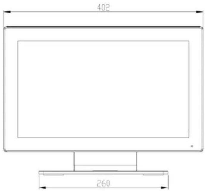
text_image
402 260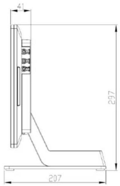
text_image
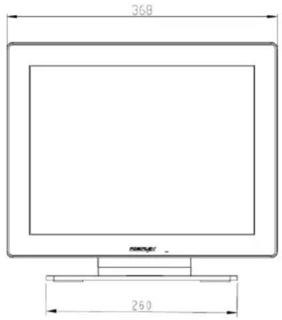
41 297 207RT-6015Q-G2
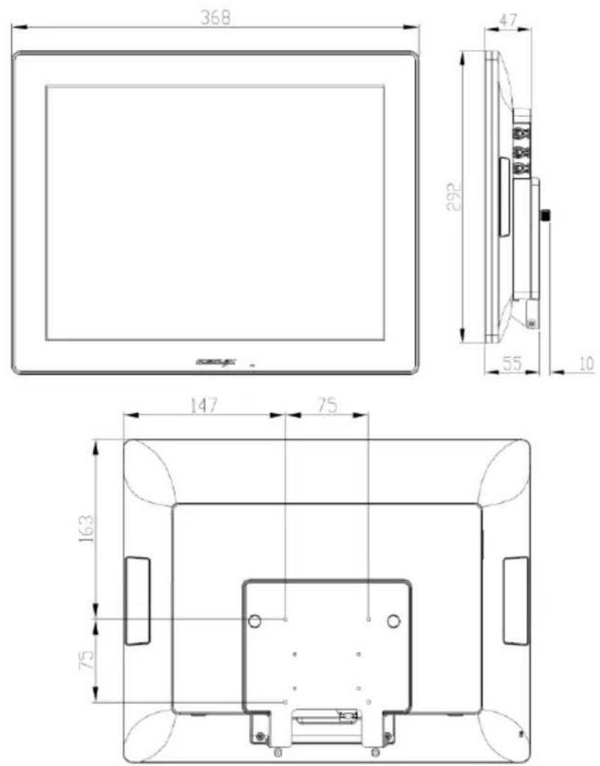
RT-6016Q-G2
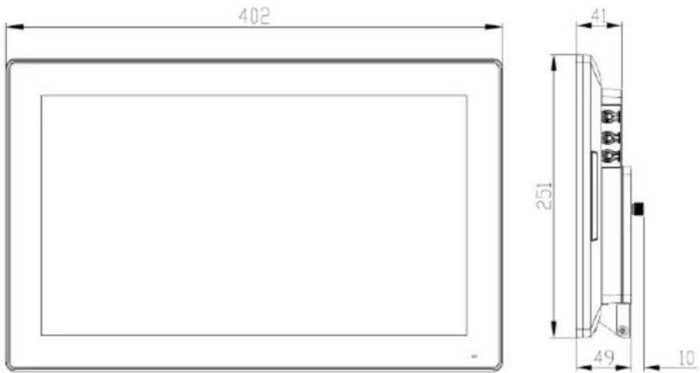

text_image
164 75 135 75※ The product information and specifications are subject to change without prior notice. To get the detailed information on the RT-6xxx-G2/6xxxQ-G2, please check this model from Posiflex Global Website.