DTH-14 V4FSN - TV DAEWOO - Free user manual and instructions
Find the device manual for free DTH-14 V4FSN DAEWOO in PDF.

User questions about DTH-14 V4FSN DAEWOO
0 question about this device. Answer the ones you know or ask your own.
Ask a new question about this device
Download the instructions for your TV in PDF format for free! Find your manual DTH-14 V4FSN - DAEWOO and take your electronic device back in hand. On this page are published all the documents necessary for the use of your device. DTH-14 V4FSN by DAEWOO.
USER MANUAL DTH-14 V4FSN DAEWOO
Safety Precautions 2
Product safety servicing guidelines for audio - video products 2
Product safety dervicing guidelines for color television receivers 3
Specifications 5
User's Instruction 6
Block Diagram 19
Alignment Instructions.... 20
Service mode adjustments.... 20
Assembly adjustments 21
SCHEMATIC DIAGRAM 25
PRINTED CIRCUIT BOARD 26
Exploded View 27
Service Parts List / Recommendable Spare Parts List 33
APPENDIX ("Appendix is provided only by internet [http://svc.dwe.co.kr]")
IC Description 39
Troubleshooting Guide 47
No power 47
No picture 48
No sound 49
CH don't stop 50
No color 51
No vertical deflection....51
No on-screen display 52
Remote control does not operate 52
CAUTION : DO NOT ATTEMPT TO MODIFY THIS PRODUCT IN ANY WAY. NEVER PEPFORM CUSTOMIZED INSTALLATIONS WITHOUT MANUFACTURER'S APPROVAL. UNAUTHORIZED MODIFICATIONS WILL NOT ONLY VOID THE WARRANTY, BUT MAY LEAD TO YOUR BEING LIABLE FOR ANT RESULTING PROPERTY DAMAGE OR USER INJURY.
SERVICE WORK SHOULD BE PERFORMED ONLY AFTER YOU ARE THOROUGHLY FAMILIAR WITH ALL OF THE FOLLOWING SAFETY CHECKS AND SERVICING GUIDELINES. TO DO OTHERWISE, INCREASES THE RISK OF POTENTIAL HAZARDS AND INJURY TO THE USER.
WHILE SERVICING, USE AN ISOLATION TRANSFORMER FOR PROTECTION FROM A.C.LINE SHOCK.
SAFETY CHECKS
AFTER THE ORIGINAL SERVICE PROBLEM HAS BEEN CORRECTED, A CHECK SHOULD BE MADE OF THE FOLLOWING :
SUBJECT : FIRE & SHOCK HAZARD
- BE SURE THAT ALL COMPONENTS ARE POSITIONED IN SUCH A WAY AS TO AVOID POSSIBILITY OF ADJACENT COMPONENT SHORTS. THIS IS ESPECIALLY IMPORTANT ON THOSE MODULES WHICH ARE TRANSPORTED TO AND FROM THE REPAIR SHOP.
- NEVER RELEASE A REPAIR UNLESS ALL PROTECTIVE DEVICES SUCH AS INSULATORS, BARRIERS, COVERS, SHIELDS, STRAIN RELIEFS, POWER SUPPLY CORDS, AND OTHER HARDWARE HAVE BEEN REINSTALLED PER ORIGINAL DESIGN. BE SURE, THAT THE SAFETY PURPOSE OF THE POLARIZED LINE PLUG HAS NOT BEEN DEFEATED.
- SOLDERING MUST BE INSPECTED TO DISCOVER POSSIBLE COLD SOLDER JOINTS, SOLDER SPLASHES OF SHARP SOLDER POINTS. BE CERTAIN TO REMOVE ALL LOOSE FOREIGN PARTICLES.
- CHECK FOR PHYSICAL EVIDENCE OF DAMAGE OF DETERIORATION TO PARTS AND COMPONENTS, FOR FRAYED LEADS, DAMAGED INSULATION (INCLUDING A.C. CORD), AND REPLACE IF NECESSARY. FOLLOW ORIGINAL LAYOUT, LEAD LENGTH AND DRESS.
- NO LEAD OR COMPONENT SHOULD TOUCH A RECEIVING TUBE OR A RESISTOR RATED AT 1 WATT OR MORE. LEAD TENSION AROUND PRO-TRUDING METAL SURFACES MUST BE AVOIDED.
- ALL CRITICAL COMPONENTS SUCH AS FUSES, FLAMEPROOF RESISTOR, CAPACITORS, ETC. MUST BE REPLACED WITH EXACT FACTORY TYPES. DO NOT USE REPLACEMENT COMPONENTS OTHER THAN THOSE SPECIFIED OR MAKE UNRECOMMENDED CIRCUIT MODIFICATIONS.
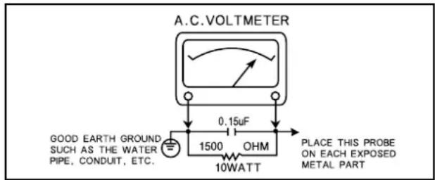
- AFTER RE-ASSEMBLY OF THE STE ALWAYS PERFORM AN A.C. LEAKAGE TEST ON ALL EXPOSED METALLIC PARTS OF THE CABINET. (THE CHANNEL SELECTOR KNOB, ANTENNA TERMINALS, HANDLE AND SCREWS) TO BE SURE THE SET IS SAFE TO OPERATE WITHOUT DANGER OF ELECTRICAL SHOCK. DO NOT USE A LINE ISOLATION TRANSFORMER DURING THIS TEST USE AN A.C. VOLTMETER, HAVING 5000 OHMS PER VOLT OR MORE SENSITIVITY, IN THE FOLLOWING MANNER: CONNECT A 1500 OHM 10 WATT RESISTOR, PARALLELED BY A .15 MFD. 150V A.C. TYPE CAPACITOR BETWEEN A KNOWN GOOD EARTH GROUND (WATER POPE, CONDUIT, ETC.) AND THE EXPOSED METALLIC PARTS, ONE AT A TIME. MEASURE HE A.C. VOLTAGE ACROSS THE COMBINATION OF 1500 OHM RESISTOR AND. 15 MFD CAPACITOR. REVERSE THE A.C. PLUG AND REPEAT A.C. VOLTAGE MEASUREMENTS FOR EACH EXPOSED METALLIC PART. VOLTAGE MEASURED MUST NOT EXCEED .75 VOLTS R.M.S THIS CORRESPONDS TO 0.5 MILLIAMP A.C. NAY VALUE EXCEEDING THIS LIMIT CONSTITUTES A POTENTIAL SHOCK HAZARD AND MUST BE CORRECTED IMMEDIATELY.
text_image
A.C.VOLTmeter 0.15µF GOOD EARTH GROUND SUCH AS THE WATER PIPE, CONDUIT, ETC. 1500 OHM 10WATT PLACE THIS PROBE ON EACH EXPOSED METAL PARTSUBJECT : GRAPHIC SYMBOLS

THE LIGHTNING FLASH WITH ARROWHEAD SYMBOL, WITHIN AN EQUILATERAL TRIANGLE, IS INTENDED TO ALERT THE SERVICE PERSONNEL TO THE PRESENCE OF UNINSULATED "DANGEROUS VOLTAGE" THAT MAY BE OF SUFFICIENT MAGNITUDE TO CONSTITUTE A RISK OF ELECTRIC SHOCK.

THE EXCLAMATION POINT WITHIN AN EQUILATERAL TRIANGLE IS INTENDED TO ALERT THE SERVICE PERSONNEL TO THE PRESENCE OF IMPORTANT SAFETY INFORMATION ON SERVICE LITERATURE.
SUBJECT : X-RADIATION
- BE SURE PROCEDURES AND INSTRUCTIONS TO ALL SERVICE PERSONNEL COVER THE SUBJECT OF X-RADIATION. THE ONLY POTENTIAL SOURCE OF X-RAYS IN CURRENT T.V. RECEIVERS IS THE PICTURE TUBE. HOWEVER, THIS TUBE DOES NOT EMIT X-RAYS WHEN THE HIGH VOLTAGE IS AT THE FACTORY SPECIFIED LEVEL. THE PROPER VALUE IS GIVEN IN THE APPLICABLE SCHEMATIC. OPERATION AT HIGHER VOLTAGES MAY CAUSE A FAILURE OF THE PICTURE TUBE OR HIGH VOLTAGE SUPPLY AND UNDER CERTAIN CIRCUMSTANCES, AMY PRODUCE RADIATION IN EXCESS OF DESIRABLE LEVELS.
- ONLY FACTORY SPECIFIED C.R.T ANODE CONNECTORS MUST BE USED. DEGAUSSING SHIELDS ALSO SERVE AS X-RAY SHIELD IN COLOR SETS. ALWAYS RE-INSTALL THEM.
- IT IS ESSENTIAL THAT SERVICE PERSONNEL HAVE AVAILABLE AN ACCURATE AND RELIABLE HIGH VOLTAGE METER. THE CALIBRATION OF THE METER SHOULD BE CHECKED PERIODICALLY AGAINST A REFERENCE STANDARD. SUCH AS THE ONE AVAILABLE AT YOUR DISTRIBUTOR.
- WHEN THE HIGH VOLTAGE CIRCUITRY IS OPERATING PROPERLY THERE IS NO POSSIBILITY OF AN X-RADIATION PROBLEM. EVERY TIME A COLOR CHASSIS IS SERVICED, THE BRIGHTNESS SHOULD BE RUN UP AND DOWN WHILE MONITORING THE HIGH VOLTAGE WITH A METER TO BE CERTAIN THAT THE HIGH VOLTAGE DOES NOT EXCEED THE SPECIFIED VALUE AND THAT IT IS REGULATING CORRECTLY. WE SUGGEST THAT YOU AND YOUR SERVICE ORGANIZATION REVIEW TEST PROCEDURE SO THAT VOLTAGE REGULATION IS ALWAYS CHECKED AS A STANDARD SERVICING PROCEDURE, AND THAT THE HIGH VOLTAGE READING BE RECORDED ON EACH CUSTOMER'S INVOICE.
- WHEN TROUBLESHOOTING AND MAKING TEST MEASUREMENTS IN A PRODUCT WITH A PROBLEM OF EXCESSIVE HIGH VOLTAGE, AVOID BEING UNNECESSARILY CLOSE TO THE PICTURE TUBE AND THE HIGH VOLTAGE SUPPLY. DO NOT OPERATE THE PRODUCT LONGER THAN IS NECESSARY TO LOCATE THE CAUSE OF EXCESSIVE VOLTAGE.
- REFER TO HV, B+ AND SHUTDOWN ADJUSTMENT PROCEDURES DESCRIBED IN THE APPROPRIATE SCHEMATIC AND DIAGRAMS (WHERE USED).
SUBJECT : IMPLOSION
- ALL DIRECT VIEWED PICTURE TUBES ARE EQUIPPED WITH AN INTEGRA IMPLOSION PROTECTION SYSTEM. BUT CARE SHOULD BE TAKEN TO AVOID DAMAGE DURING INSTALLATION. AVOID SCRATCHING THE TUBE. OF SCRATCHED REPLACE IT.
- USE ONLY RECOMMENDED FACTORY REPLACEMENT TUBES.
SUBJECT : TIPS ON PROPER INSTALLATION
- NEVER INSTALL ANY PRODUCT IN A CLOSED-IN RECESS, CUBBYHOLE OR CLOSELY FITTING SHELF SPACE, OVER OR CLOSE TO HEAT DUCT, OR IN THE PATH OF HEATED AIR FLOW.
- AVOID CONDITIONS OF HIGH HUMIDITY SUCH AS : OUTDOOR PATIO INSTALLATIONS WHERE DEW IS A FACOR, NEAR STEAM RADIATORS WHERE STEAM LEAKAGE IS A FACTOR, ETC.
- AVOID PLACEMENT WHERE DRAPERIES MAY OBSTRUCT REAR VENTING. THE CUSTOMER SHOULD ALSO AVOID THE USE OF DECORATIVE SCARVES OR OTHER COVERINGS WHICH MIGHT OBSTRUCT VENTILA-TION.
- WALL AND SHELF MOUNTED INSTALLATIONS USING A COMMERCIAL MOUNTING KIT, MUST FOLLOW THE FACTORY APPROVED MOUNTING INSTRUCTIONS. A PRODUCT MOUNTED TO A SHELF OR PLATFORM MUST RETAIN ITS ORIGINAL FEET ( OR THE EQUIALENT THICKNESS IN SPACERS) TO PROVIDE ADEQUATE AIR FLOW ACROSS THE BOTTOM, BOLTS OR SCREWS USED FOR FASTENERS MUST NOT TOUCH ANY PARTS OR WIRING. PERFORM LEAKAGE TEST ON CUSTOMIZED INSTALLATIONS.
- CAUTION CUSTOMERS AGAINST THE MOUNTING OF A PRODUCT ON SLOPING SHELF OR A TILTED POSITION, UNLESS THE PRODUCT IS PROPERLY SECURED.
- A PRODUCT ON A ROLL-ABOUT CART SHOULD BE STABLE ON ITS MOUNTING TO THE CART. CAUTION THE CUSTOMER ON THE HAZARDS OF TRYING TO ROLL A CART WITH SMALL CASTERS ACROSS THRESHOLDS OR DEEP PILE CARPETS.
- CAUTION CUSTOMERS AGAINST THE USE OF A CART OR STAND WHICH HAS NOT BEEN LISTED BY UNDERWRITERS LABORATORIES. INC. FOR USE WITH THEIR SPECIFIC MODEL OF TELEVISION RECEIVER OF GENERICALLY APPROVED FOR USE WITH T.V.S OF THE SAME OR LARGER SCREEN SIZE.
- CAUTION CUSTOMERS AGAINST THE USE OF EXTENSION CORDS. EXPLAIN THAT A FOREST OF EXTENSIONS SPROUTING FROM A SINGLE OUTLET CAN LEAD TO DISASTROUS CONSEQUENCES TO HOME AND FAMILY.
CAUTION : Do not attempt to modify this product in any way. Unauthorized modifications will not only void the warranty, but may lead to your being liable for any resulting property damage or user injury. Servie work should be performed only after you are thoroughly familiar with all of the following safety checks and servicing guidelines. To do otherwise, increases the risk of potential hazards and injury to the user.
SAFETY CHECKS
After the original service problem has been corrected, a check should be made of the following :
SUBJECT : FIRE & SHOCK HAZARD
- Be sure that all components are positioned in such a way as to avoid possibility of adjacent component shorts. This is especially important on those chassis which are transported to and from the repair shop.
- Never release a repair unless all protective devices such as insulators, barriers, covers, shields, strain reliefs, and other hardware have been reinstalled per original design.
- Soldering must be inspected to discover possible cold solder joints, frayed leads, damaged insulation (including A.C. cord), solder splashes or sharp solder points. Be certain to remove all loose foreign particals.
- Check for physical evidence of damage or deterioration to parts and components, and replace if necessary follow original layout, lead length and dress.
- No leads or components should touch a receiving tube or a resistor rated at 1 watt or more. Lead tension around protruding metal surfaces must be avoided.
- All critical components such as fuses, flameproof resistors, capacitors, etc. must be replaced with exact factory types. Do not use replacement components other than those specified or make unrecommended circuit modifications.
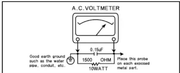
- After re-assembly of the set always perform an A.C. leakage test on all exposed metallic parts of the cabinet, (the channel selector knob, antenna terminals, handle and screws) to be sure the set is safe to operate without danger of electrical shock. Do not use a line isolation transformer during this test. Use an A.C. voltmeter, having 5000 ohms per volt or more sensitivity, in the following manner: connect a 1500 ohm 10 watt resistor, paralleled by a 15 mfd. 150V A.C. type capacitor between a known good earth ground (9water pipe, conduit, etc.) and the exposed metallic parts, one at a time. Measure the A.C. voltage across the combination of 1500 ohm resistor and 0.15 MFD capacitor. Reverse the A.C. plug and repeat A.C. voltage measurements for each exposed metallic part. Voltage measured must not exceed 0.75 volts R.M.S. This corresponds to 0.5 milliamp A.C. Any value exceeding this limit constitutes a potential shock hazard and must be corrected immediately.
text_image
A.C. VOLTmeter Good earth ground such as the water pipe, conduit, etc. 0.15uF 1500 OHM 10WATT Place this probe on each exposed metal part.GRAPHIC SYMBOLS :

The lightning flash with arrowhead symbol, within an equilateral triangle, is intended to alert the service personnel to the presence of uninsulated “dangerous voltage” that may be of sufficiently magnitude to constitute a risk of electric shock.

The exclamation point within an equilateral triangle is intended to alert the service personnel to the presence of important safety information in service literature.

Fuse symbol is printed on pcb adjacent to the fuse, with "RISK OF FIRE REPLACE FUSE AS MARKED". The symbol is explained in the service manual sith the following wording or equivalent.
"CAUTION : FOR CONTINUED PROTECTION AGAINST FIRE HAZARD, REPLACE ONLY WITH SAME TYPE (4A, 125V)" and "ATTENTION : AFIN D'ASSU UNE PROTECTION PERMANENTE CONTRE LES RISQUES D'INCENDIE, REMPLACER UNIQUEMENT PAR UN FUSIBLE DE MEME TYPE ET DE "4A, 125V".
SUBJECT : X-RADIATION
- Be sure procedures and instructions to all service personnel cover the subject of X-rays in current T.V. receivers is the picture tube. However, this does not emit X-rays when the high voltage is at the factory specified level. The proper value is given in the applicable schematic. Operation at higher voltages may cause a failure of the picture tube or high voltage supply and, under certain circumstances, may produce radiation in excess of desirable levels.
- Only factory specified C.R.T. anode connectors must be used. Degaussing shields also serve as X-ray shield in color sets. Always re-install them.
- It is essential that the serviceman has available an accurate and reliable high voltage meter. The calibration of the meter should be checked perio - dically against a reference standard. Such as the one available at your distributor.
- When the high voltage circuitry is operating properly there is no possibility of an X-radiation problem. Every time a color chassis is serviced, the brightness should be run up and down while monitoring the high voltage with a meter to be certain that the high voltage does not exceed the specified value and that it is regulating correctly. We suggest that you and your service organization review test procedures so that voltage regulation is always checked as a standard servicing procedure. And that the high voltage reading be recorded on each customer's invoice.
- When troubleshooting and making test measurements in a receiver with a problem of excessive high voltage, avoid being unnecessarily close to the picture tub eand the high voltage compartment. Do not operate the chassis longer than is necessary to locate the cause of excessive voltage.
- Refer to HV, B+ and Shutdown adjustment procedures described in the appropriate schematic and diagrams (where used).
SUBJECT : IMPLOSION
-
All direct viewed picture tubes are equipped with an integral implosion protection system, but care should be taken to avoid damage during installation. Avoid scratching the tube. If scratched, replace it.
-
Use only recommended factory replacement tubes.
SUBJECT : TIPS ON PROPER INSTALLATION
- Never install any receiver in closed-in recess, cubbyhole or colsely fitting shelf space over, or close to heat duct, or in the path of heated air flow.
- Avoid conditions of high humidity such as: Outdoor patio installations where dew is a factor. Near steam radiators where steam leakage is a factor, etc.
-
Avoid placement where draperies may obstruct rear venting. The customer should also avoid the use of decorative scarves or other coverings which might obstruct ventilation.
-
Wall and shelf mounted installations using a commercial mounting kit, must follow the factory approved mounting instructions. A receiver mounted to a shelf or platform must retain its original feet (or the equivalent thickness in spacers) to provide adequate are flow across the bottom, bolts or screws used for fasteners must not touch and parts or wiring. Perform leakage test on customized installations.
- Caution customers against the mounting of a receiver on sloping shelf or a tilted position, unless the receiver is properly secured.
- A receiver on a roll-about cart should be stable on its mounting to the cart. Caution the customer on the hazards of trying to roll a cart with small casters across thresholds or deep pile carpets.
- Caution customers against the use of a cart of stand which has not been listed by underwriters laboratories, inc. For use with their specific model of television receiver or generically approved for use with T.V.'s of the same or larger screen size.
Specifications
| ITEMS DTH-14V3FSN DTH-20V3FSN | MODEL DTH-14V1FSN DTH-20V1FSN REMARKSDTH-14V4FSN DTH-20V4FSN | |
| TV STANDARD NTSC-M, PAL N/M | ||
| POWER INPUT AC160-260V, 50/60 Hz | ||
| POWER CONSUMPTION 14"=55W , 20"=70W | ||
| TUNING SYSTEM Frequency Synthesizer (FS) Tuning System | ||
| TUNING RANGES VHS : 2~13 (12) | UHF : 2~13 (56)CATV : 1~125 (125) | |
| SOUND OUTPUT 3W | ||
| SPEAKER 3 W 8 ohm | ||
| ANTENNA INPUT IMPEDANCE 75 ohm Unbalanced | ||
| AUXILIARYINPUT TERMINAL | Front : Video, Audio, Ear phoneRear : Video, Audio | |
| INTERMEDIATEFREQUENCIES | Picture IF Carrier Frequency : 45.75 MHzSound IF Carrier Frequency : 45.25 MHzColor Sub-Carrier Frequency : 42.17 MHz | |
| REMOTE CONTROL | R-43A01 | |
| SPCEIAL FUNCTIONS | 3-Language OSDWith CAPTIONWake-up/Off TimeSleep TimerPower Restore | |
User's Instruction
Overview of Your Equipment
Your TV comes with a remote control. The section below summarizes the buttons, controls, and terminals that your will use with your TV.
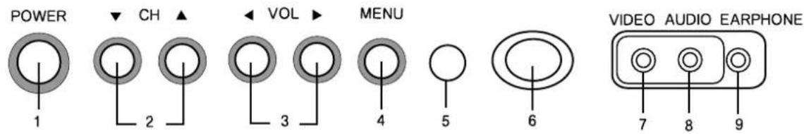
Your TV's Front Panel
text_image
POWER 1 CH ▲ 2 VOL ▶ 3 MENU 4 5 6 VIDEO AUDIO EARPHONE 7 8 91 POWER
Use this button to turn your TV or off.
2 ▼C ▲H
Use these buttons to change channels on your TV, or to select items in the menu system.
3 ◀ V O▶ L
Use these buttons to change your TV's volume, to activate selections in the mean system, or to change audio and video settings.
4 MENU
Use this button to turn the TV's menu system on and off.
5 STAND-BY(red) indication
This indicator lights up when the AC power cord is connected to a power source.
6 Remote Control Receiver
This receiver receives a signal from your remote control. Do not block it.
7 VIDEO IN jack
Use this jack to receive a video signal from another A/V component.
8 AUDIO IN jack
Use this jack to receive an audio signal from another A/V component.
9 EARPHONE jack
Use this jack to receive an audio signal from your TV.
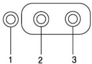
Your TV's Back Panel
ANT VIDEO AUDIO
flowchart
graph TD
    A[" "] --> B[" "]
    C[" "] --> D[" "]
    E[" "] --> F[" "]
1 Antenna terminal (ANT)
Use this terminal to attach an antenna or cable system to your TV.
2 VIDEO IN
This terminal allows the TV to receive a video signal from another component, such as a VCR.
3 AUDIO IN
This terminal allows the TV to receive an audio signal from another component, such as a VCR.
Your Remote Control
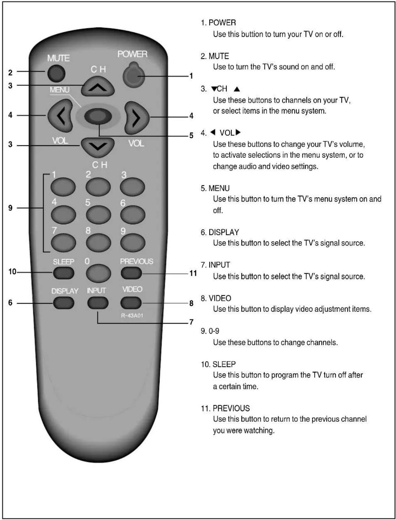
text_image
1. POWER Use this button to turn your TV on or off. 2. MUTE Use to turn the TV's sound on and off. 3. ▼CH ▲ Use these buttons to channels on your TV, or select items in the menu system. 4. ◀ VOL▶ Use these buttons to change your TV's volume, to activate selections in the menu system, or to change audio and video settings. 5. MENU Use this button to turn the TV's menu system on and off. 6. DISPLAY Use this button to select the TV's signal source. 7. INPUT Use this button to select the TV's signal source. 8. VIDEO Use this button to display video adjustment items. 9. 0-9 Use these buttons to change channels. 10. SLEEP Use this button to program the TV turn off after a certain time. 11. PREVIOUS Use this button to return to the previous channel you were watching.Operating Your TV
Once you have connected your TV to an antenna or cable system, plugged the TV in, and put batteries in the remote, you are ready to use the TV. The first thing you should do is program your TV so it memorizes all of available channels.
Turning Your TV On
natural_image
Simple line drawing of a remote control with buttons and a keypad (no text or symbols)1 To turn your TV, press the POWER button on the front panel then. press the ▼CH▲, ◀VOL▶ or MENU bottom. You can also use the POWER button on the remote control. Make sure your TV is plugged in before you try to turn it on.
Programming Your TV's Channel Memory
Your TV's memory determines the channels that are available using the ▼ CH▲ buttons. If a channel is not in memory, you can tune to it with the number buttons, but not with the ▼ CH▲ buttons. Follow these steps to program your TV's memory :
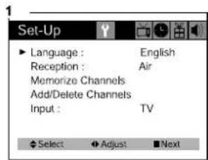
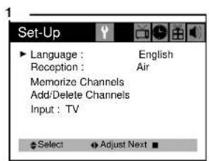
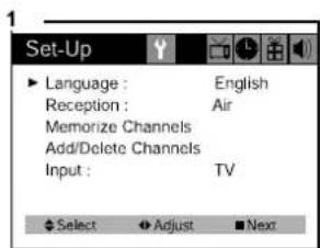
1 With the TV on, press the MENU button twice, then "Set-Up" menu will appear.
2 Use the ▼CH ▲buttons to select "Reception", the use the ◀VOL ▶ button to select 'Air' or 'Cable'. If you connected an antenna to your TV, select 'Air': If you connected a cable system, select 'Cable'
3 Use the ▼CH ▲buttons to select "Memorize Channels", then use the ◀VOL ▶button to enter the "Memorize Channels" process. Again press the ◀VOL▶ button to begin.
4 Press the MENU button to return to Set-Up menu.
5 Press the MENU button three times to return to normal TV viewing.
Your TV's channel memory will not be affected by a power outage. You will not need to re-program the memory unless you change the type of cable or antenna connected to your TV.
text_image
Set-Up Language : English Reception : Air Memorize Channels Add/Delete Channels Input : TV Select Adjust Next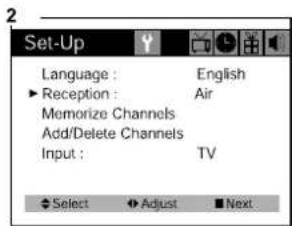
text_image
Set-Up Language : English ► Reception : Air Memorize Channels Add/Delete Channels Input : TV Select Adjust Next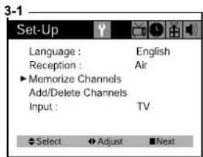
text_image
Set-Up Language : English Reception : Air Memorize Channels Add/Delete Channels Input : TV Select Adjust Next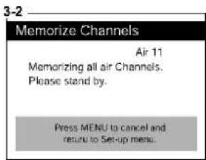
text_image
3-2 Memorize Channels Air 11 Memorizing all air Channels. Please stand by. Press MENU to cancel and return to Set-up menu.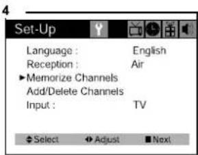
text_image
Set-Up Language : English Reception : Air ▶Memorize Channels Add/Delete Channels Input : TV Select ▶Adjust □Next
natural_image
Empty rectangular frame with no text, numbers, or symbolsChanging Channels
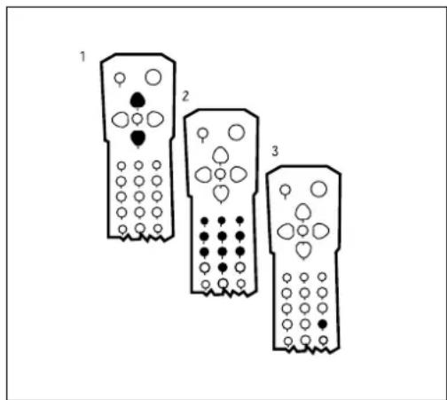
You can change channels in three ways :
text_image
1 2 31 The ▲CH▼buttons will take you through all memorized channels, one by one. The ▲CH▼ buttons will not access channels that have not been programmed into the TV's memory. For more information about programming channels into memory, see the section "Programmining your TV's Channel Memory" on the previous page.
2 The number buttons (0-9) will take you to any channel, even if it has not been memorized. To change to a channel, enter its number: the TV will tune to the new channel when you enter the second digit of the channel.
3 The PREVIOUS button will take you instantly to the last channel you were watching.
Changing the Volume
natural_image
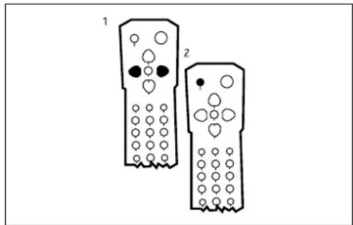
Two identical remote control devices with circular buttons and a single button, labeled 1 and 2 (no text or symbols on the devices themselves)1 The change the volume of the TV set, use the ◀ VOL▶ buttons on the remote or on the front panel.
2 To quickly turn off the sound, press the MUTE button on the remote. The 'MUTE' will appear on screen, colored green. To return the volume to its previous level, press MUTE again.
Changing the TV's Channel Memory
Your TV's memory determines the channels that are available using the ▲ CH▼ buttons. You can add channels to this memory or remove them from memory. If a channel is removed from memory, you can tune to with the number buttons, but you cannot tune to it with the ▲ CH▼ buttons.
If there are just one channel memorized, then the Add/Delete Channels function will search the whole channels. But if there are two or more channel memorized, then the Add/Delete Channels function will search the memorized channels only.
Adding/Deleting a channel to memory
1 Use the number buttons to tune to the channel.
2 Press the MENU button twice, then "Set-Up" menu will display.
3 Use the ▲CH▼ buttons to select "Add/Delete Channels", then use the◀ VOL▶ button to enter the "Add/Delete Channels" process.
4 If the channel is not in memory, then use the ◀VOL ▶button to add the channel from memory.
5 If the channel is in memory, then use the ◀VOL ▶ button to delete the channel from memory.
6 If you are going to delete other channel, then press the ▲CH ▼buttons until desired channel is selected. And press the ◀VOL ▶button to delete the channel.
7 Wait 10 seconds, or press the MENU button four times to exit.
text_image
1 11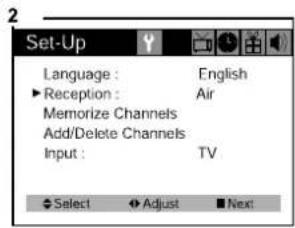
text_image
Set-Up Language : English ►Reception : Air Memorize Channels Add/Delete Channels Input : TV Select Adjust Next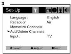
text_image
Set-Up Language : English Reception : Air Memorize Channels ▶ Add/Delete Channels Input : TV Select Adjust Next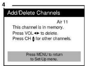
text_image
Add/Delete Channels Air 11 This channel is in memory. Press VOL ← to delete. Press CH ↓ for other channels. Press MENU to return to Set-Up menu.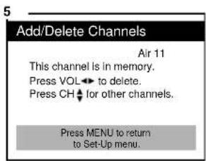
text_image
Add/Delete Channels Air 11 This channel is in memory. Press VOL← to delete. Press CH← for other channels. Press MENU to return to Set-Up menu.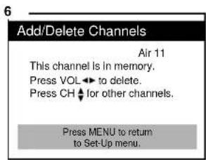
text_image
Add/Delete Channels Air 11 This channel is in memory. Press VOL ↩ to delete. Press CH ↕ for other channels. Press MENU to return to Set-Up menu.Displaying the Current Channel
natural_image
Simple line drawing of a remote control with buttons and a keypad (no text or symbols)1 To quickly see the current channel number and status, press DISPLAY button on the remote control. The current channel number and status will be displayed.
Changing the TV's Input
Normally, your TV displays the signal coming through the antenna terminal.
However, If you've connected another component to your TV(such as a VCR) using the Video/Audio input, you will want to be able to view the signal from the component.
To do this, you will need to switch from the 'TV' input to the 'Line' Input, as follows.
1 With the TV on, press the MENU button twice, then "set-up" menu will appear.
2 Use the ▲CH▼ buttons to select "Input".
3 Press the ◀ VOL▶ buttons to change from 'TV' to 'Line'.
4 Wait 10 seconds, or press the MENU button to return to normal TV viewing.
text_image
Set-Up Language : English Reception : Air Memorize Channels Add/Delete Channels Input : TV Select Adjust Next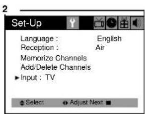
text_image
Set-Up Language : English Reception : Air Memorize Channels Add/Delete Channels Input : TV Select Adjust Next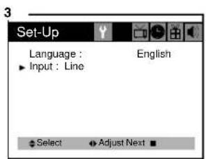
text_image
Set-Up Language : Input : Line English Select Adjust NextWhen it connected an Video/Audio cable from the Video/Audio out jack on the VCR to the Video/Audio in jack on the front your TV, and your 'TV's back panel at the same time, the latter takes precedence of the former.
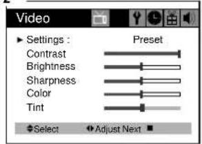
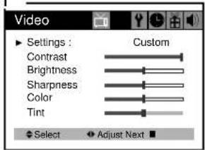
Adjusting Video Settings
You may wish to adjust the video settings (e.g. contrast or color) to obtain the most pleasing picture. To do so, follow these directions:
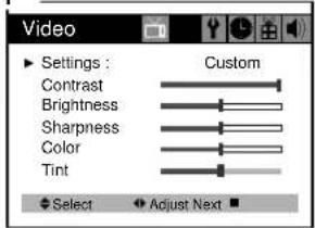
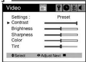
1 With the TV on, press the MENU button. then "Video" menu will appear.
2 The "Settings" item will be selected. Use the ◀ VOL ▶ buttons to turn Settings to Preset or Custom.
3 Use the ▲CH▼ buttons to select the video setting you wish to adjust. Descriptions of the video settings are on the next page.
4 Use the ◀VOL ▶buttons to adjust the video setting to the level you prefer.
5 Use the ▲CH ▼buttons to select another video setting to adjust.
6 When you are finished, press the MENU button until menu OSD will be disappeared.
1
text_image
Video Settings : Custom Contrast Brightness Sharpness Color Tint Select Adjust Next2
text_image
Video Settings : Preset Contrast Brightness Sharpness Color Tint Select Adjust Next3
text_image
Video Settings : Preset Contrast Brightness Sharpness Color Tint Select Adjust NextA
text_image
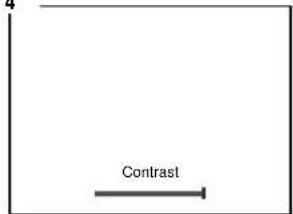
4 ContrastE

text_image
BrightnessC
natural_image
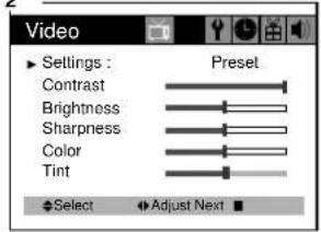
Empty white square with a thin black border (no text or symbols)Returning to the factory settings
If you would like to return to the original video settings, as they were calibrated at the factory, follow these steps :
1 With the TV on, pres the MENU button. then "Video" menu will appear.
2 Press the ◀ VOL▶ buttons to set the "Settings" to 'Preset'.
The TV will remember the 'Custom' settings you had previously chosen. When you set "Settings" to "Custom" again, your previous custom settings will be restored.
1
text_image
Video Settings : Custom Contrast Brightness Sharpness Color Tint Select Adjust Next2
text_image
Video Settings : Preset Contrast Brightness Sharpness Color Tint Select Adjust NextF

natural_image
Blank white image with a thin black border (no text, symbols, or markings)Descriptions of video settings
The contrast setting controls the relation between the light and black areas of the screen. If the light areas are too bright and are losing details, press the ◀ VOL button ; if the picture is gray and lacks contrast, press the VOL ▶ button.
The brightness settings controls the overall amount of light in the picture. If the picture is too bright, press the ◀ VOL button; if the picture is too dark, press the VOL▶ button.
Sharpness controls how the TV displays edges of objects on-screen. If the TV shows multiple vertical lines at the edges of an object, press the ◀ VOL button ; if the vertical edges of on-screen objects are fuzzy, press the VOL ▶ button.
The color setting controls the intensity of color. If the color is over-saturated, press the VOL ▶ button; if the color is washed out, press the VOL▶ button.
The tint setting controls the relationship of red and green in a picture. Tint is especially noticeable in flesh tones. If flesh tones seem too red or purple, press the VOL ▶ button; if flesh tones are too green, press the VOL ▶ button.
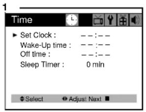
Using Timer Functions
Your TV has a built in-clock, and you can set the TV to turn on and off at times that you select. You can also set your TV to turn off after counting down a certain amount of time.
Setting the Clock
1 With the TV turned on, press the MENU button until "Time" menu will be displayed.
2 The "Set Clock" item will be selected. Press the ◀ VOL ▶ buttons to set the clock. If you hold down either ◀ VOL or VOL ▶ button, the corresponding numbers will change more quickly.
3 When the clock is set correctly, use the ▲CH ▼ buttons to select another “Time” function, or press the MENU button until menu OSD will be disappeared.
text_image
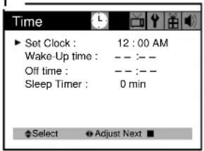
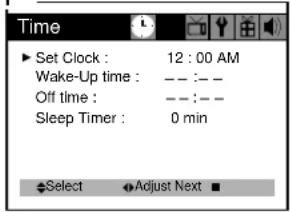
1 Time ▶ Set Clock : --:-- Wake-Up time : --:-- Off time : --:-- Sleep Timer : 0 min Select ▶ Adjust: Next ■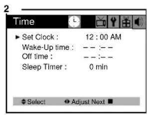
text_image
Time Set Clock : 12 : 00 AM Wake-Up time : -- :-- Off time : -- :-- Sleep Timer : 0 mln Select Adjust Next ■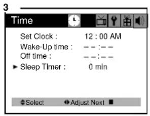
text_image
3 Time Set Clock : 12 : 00 AM Wake-Up time : -- : -- Off time : -- : -- ► Sleep Timer : 0 mln Select ▶ Adjust Next ■Settings the Wake-up timer
If you enter a time in the “Wake-up time” setting, your TV will automatically turn on at that time. Follow these instructions to set the “Wake-up time”.
After Wake-up Timer turned on the TV set, if user do not input the user control (e.g. remote CH or VOL key) within 15 minutes, the TV set will turn off automatically. If user input the user control within 15 minutes, the TV set will turn on continuously. It is safety feature for prevent from any kind of problem without human control.
1 With the TV turned on, press the MENU button until "Time" menu will be displayed.
2 Use the ▲CH▼ buttons to select "Wake-up time" item.
3 If you hold down either ◀ VOL or VOL▶ button, the corresponding numbers will change more quickly.
4 When the setting is corret, use the ▲CH▼ buttons to select another "Time" function, or press the MENU button until menu OSD will be disappeared.
1
text_image
Time ▶ Set Clock : 12 : 00 AM Wake-Up time : -- :-- Off time : -- :-- Sleep Timer : 0 min Select ▼ Adjust Next ■2
text_image
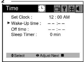
Time Set Clock : 12 : 00 AM ► Wake-Up time : -- :-- Off time : -- :-- Sleep Timer : 0 min Select ▶ Adjust Next ■3
text_image
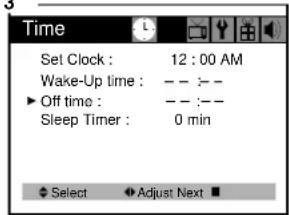
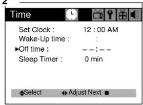
Time Set Clock : 12 : 00 AM Wake-Up time : -- :-- ▶ Off time : -- :-- Sleep Timer : 0 min Select Adjust Next ■Setting Off Timer
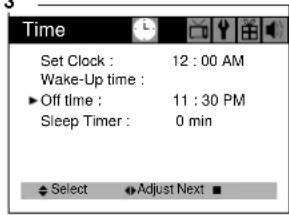
If you enter a time in the “Off time” setting, your TV will automatically turn off at that time. Follow these instructions to set the “Off time”.
1 With the TV turned on, press the MENU button until "Time" menu will be displayed.
2 Use the ▲ CH▼ buttons to select "Off time" item.
3 If you hold down either ◀VOL or VOL ▶button, the corresponding numbers will change more quickly.
4 When the setting is correct, use the ▲CH▼buttons to select another "Time" function, or press the MENU button until menu OSD will be disappeared.
1
text_image
Time ▶ Set Clock : 12 : 00 AM Wake-Up time : — — — Off time : — — — Sleep Timer : 0 min Select Adjust Next ■2
text_image
Time Set Clock : 12 : 00 AM Wake-Up time : ▶Off time : —:— Sleep Timer : 0 min Select ▶Adjust Next ■3
text_image
Time Set Clock : 12 : 00 AM Wake-Up time : ▶ Off time : 11 : 30 PM Sleep Timer : 0 min Select ▼Adjust Next ■Canceling the Wake-up Timer of Off Timer
If you would like to cancel the Wake-up Timer or the Off Timer, Press the ◀ VOL▶ buttons until the timer settings return to “- -:- -”.
The Wake-up Timer and Off Timer will not function correctly unless the clock has been set.
Setting the Sleep Timer
The sleep timer allows you to set an amount of time from 15 minutes to 120 minutes. TV will count down the amount of time you set, then turn itself off. To set the sleep timer :
1 With the TV turned on, press the MENU button until "Time" menu will be displayed.
2 Use the ▲CH▼ buttons to select "Sleep timer" item.
3 Use the ◀VOL ▶ buttons to set the sleep time. Each time you press VOL, you step between the available sleep times : 15min, 30min, 45min, 60min, 90min, or 120min.
4 When the setting is correct, use the ▲CH▼ buttons to select another "Time" function, or press the MENU button until menu OSD will be disappeared.
5 You can also set the "Sleep Timer" during normal TV viewing, simply by pressing the SLEEP button on the remote control. This button steps through the available sleep times (see step 3), one by one.
To cancel the Sleep timer, turn the TV off, or set the sleep time to "0" using one of the methods described above.
text_image
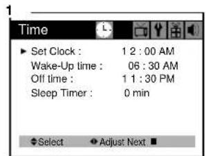
Time ▶ Set Clock : 1 2 : 00 AM Wake-Up time : 06 : 30 AM Off time : 1 1 : 30 PM Sleep Timer : 0 min ◆Select ▼Adjust Next ■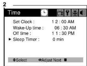
text_image
2 Time Set Clock : 1 2 : 00 AM Wake-Up time : 06 : 30 AM Off time : 1 1 : 30 PM ► Sleep Timer : 0 min ◆Select ▼Adjust Next ■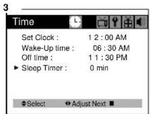
text_image
3 Time Set Clock : 1 2 : 00 AM Wake-Up time : 06 : 30 AM Off time : 1 1 : 30 PM ► Sleep Timer : 0 min ◆ Select ▼ Adjust Next ■Additional Features
This section contains descriptions of the more advanced features of your TV.
Changing the Language of the On-screen Menus
You can choose to display the on-screen menus in English, Spanish, French. To change the on-screen language :
1 With the TV on, press the MENU button twice, then "Set-Up" menu will appear.
2 The "Language" item will be selected. Press the ◀VOL▶ buttons to select the language you want to use : English, Spanish, French.
3 To return normal TV viewing, press the MENU button until menu OSD will be disappeared.
text_image
Set-Up Language : English Reception : Air Memorize Channels Add/Delete Channels Input : TV Select Adjust Next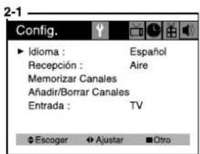
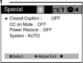
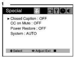
Many TV shows contains “closed captions”. These captions are hidden words that can be displayed on your TV screen. There are two types of these words: “captions” usually follow the action on-screen, providing a written version of the dialogue, narration, and sound effects; “text” is not usually related to the action on-screen, often providing information such as news or weather. A TV program might be providing more than one set of captions or one set of text.
To set your TV to display captions or text.
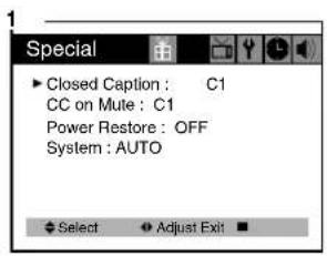
1 With the TV turned on, press the MENU button until "Special" menu will be displayed.
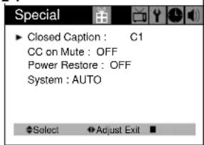
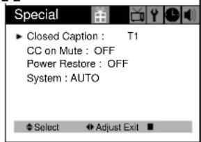
2 The "Closed Caption" item be selected. To turn captioning on, use the ◀VOL▶ buttons to select Captions (C1 or C2) or Text (T1 or T2). At the time these instructions were written, only C1 is normally available, but feel free to try the other selections.
3 Wait 10 seconds, or press the MENU button to return to normal TV viewing. Your setting will remain intact until you change it.
。
text_image
Special ► Closed Caption : OFF CC on Mute : OFF Power Restore : OFF System : AUTO ◆ Select ▼ Adjust Exit ■2-1
text_image
Special ► Closed Caption : C1 CC on Mute : OFF Power Restore : OFF System : AUTO ◆Select ▼Adjust Exit ■2-2
text_image
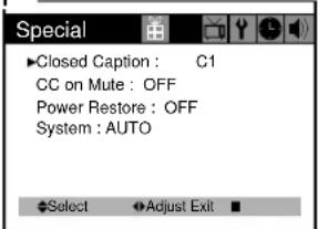
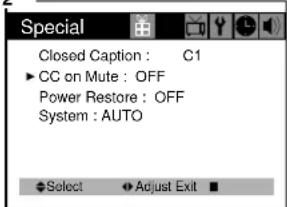
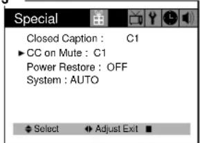
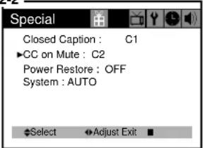
Special ► Closed Caption : T1 CC on Mute : OFF Power Restore : OFF System : AUTO ◆ Select ▶ Adjust Exit ■CC on Mute
When the sound is muted, user can select the caption display. It will display the caption content instead of sound mute.
1 With the TV turned on, press the MENU button until "Special" menu will be displayed.
2 Use the ▲CH▼ buttons to select "CC on Mute" item.
3 Use the ◀ VOL ▶ buttons to select "C1" or "C2".
1
text_image
Special ►Closed Caption : C1 CC on Mute : OFF Power Restore : OFF System : AUTO Select Adjust Exit2
text_image
Special Closed Caption : C1 ► CC on Mute : OFF Power Restore : OFF System : AUTO Select Adjust Exit ■3
text_image
Special Closed Caption : C1 ▶ CC on Mute : C1 Power Restore : OFF System : AUTO Select Adjust Exit2-2
text_image
Special Closed Caption : C1 ▶CC on Mute : C2 Power Restore : OFF System : AUTO Select ▶Adjust Exit ■Power Restore
User can select the On/Off status when the power cord put into the wall outlet. If user have a cable box with AC outlet, then user can connect the TV power cord to the AC outlet and control the TV without TV remote control. This function is rarely used for home use, so special care is needed while using.
1 With TV turned on, press the MENU button until "Special" menu will be displayed.
2 Use the ▲CH ▼buttons select "Power Restore" item.
3 Use the ◀VOL▶ buttons to select "On" or "Off".
text_image
Special ► Closed Caption : C1 CC on Mute : C1 Power Restore : OFF System : AUTO ◆ Select ▼ Adjust Exit ■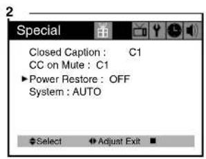
text_image
Special Closed Caption : C1 CC on Mute : C1 ▶Power Restore : OFF System : AUTO Select ▶Adjust Exit ■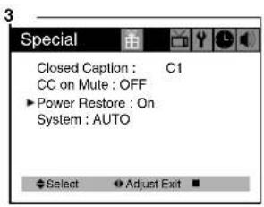
text_image
Special Closed Caption : C1 CC on Mute : OFF Power Restore : On System : AUTO Select Adjust ExitSystem
User can select the AUTO/PAL-M/PAL-N/NTSC color system modes.
If you have no color problem when see the FF mode of VCR or non standard signal, you must choose the NTSC of color system modes.
- With the TV turned on, press the MENU button until "Special" menu will be displayed.
- Use the ▲ CH▼ buttons select "system" item.
- Use the ◀ VOL ▶ buttons to select "AUTO", "PAL-M", "PAL-N" or "NTSC"
text_image
Special ► Closed Caption : OFF CC on Mute : OFF Power Restore : OFF System : AUTO ◆ Select ◆ Adjust Exit ■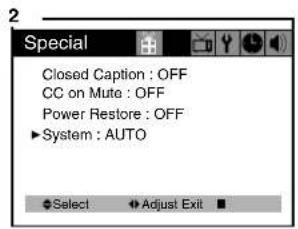
text_image
Special Closed Caption : OFF CC on Mute : OFF Power Restore : OFF ►System : AUTO Select Adjust Exit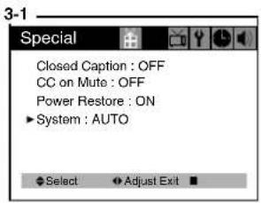
text_image
Special Closed Caption : OFF CC on Mute : OFF Power Restore : ON ►System : AUTO Select Adjust Exit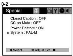
text_image
Special Closed Caption : OFF CC on Mute : OFF Power Restore : ON ►System : PAL-M Select Adjust Exit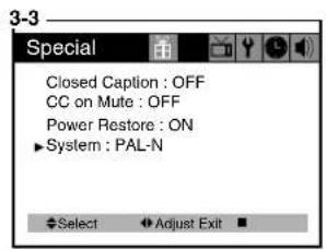
text_image
Special Closed Caption : OFF CC on Mute : OFF Power Restore : ON ►System : PAL-N Select Adjust Exit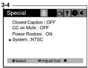
text_image
Special Closed Caption : OFF CC on Mute : OFF Power Restore : ON ►System : NTSC Select Adjust ExtTroubleshooting
Your Daewoo television is designed to give you trouble-free performance for many years. If you have a problem with your TV, try the solutions listed below.
If the suggestions listed below do not solve your problem, contact your Daewoo dealer or an authorized Daewoo service center. You can also call Daewoo directly at 1-800-DAEWOO8.
There is no pictrue or sound, or the TV won't turn on.
- Make sure the TV is plugged in.
- Make sure the MUTE is not set.
• Make sure the power is on. - If there is neither picture or sound, unplug the TV for 30 seconds. then plug it in and try again.
There is no picture or sound on some UHF channels.
- Try another station. If the other stations are OK, it may be a station problem.
- Check that the antenna is connected, is in good working order, has no broken wires, and is adjusted correctly.
• See if anything is interfering with the antenna signal. - Make sure the AIR/CABLE setting is correct.
The sound is OK, but he picture is poor.
- Try another station. If the other stations are OK, it may be a station problem.
- Check that the antenna is connected and is in good working order, has no broken wires and is adjusted correctly.
The picture is OK, but the sound is poor.
- Try another station. If the other stations are OK, it may be station problem.
- Check that the antenna is connected, is in good working order, has no broken wires, and adjusted correctly.
There is poor reception on some channels.
- Try another station. If the other stations are OK, it may be a station problem.
- Check that the antenna is connected, is in good working order, has no broken wires, and is adjusted correctly.
You cannot tune to a cable channel.
- Make sure the AIR/CABLE setting is correct.
- The channel may not be programmed into memory. USER'S INSTRUCTION
The picture rolls, slants, shows lines, is grainy, has poor color, or has ghosts.
- Try another station. If the other station are OK, it may be a station problem.
- Check that the antenna is connectedm is in good working order, has no broken wires and is adjusted correctly.
• See of anything is interfering with the antenna signal.
The remote control does not work.
- Make sure the TV is plugged in.
- Make sure there are fresh batteries in the remote control.
- Make sure there is nothing blocking the remote control signal.
WARRANTY
Daewoo Electronics Corporation of America warrants each new electronic product manufactured by it to be free from defective material and workmanship and agrees to remedy any such defect or to furnish a new part (at the Company's option) in exchange for any part of any unit of its manufacture which under normal installation, use, and service disclosed such defect, provided the unit is delivered by the owner to us or to our authorized distributor from whom purchased or authorized service station, intact for our examination with all transportation charges prepaid to our factory. To establish and receive warranty service at our factory or authorized service facilities, proof of purchase/dated sales invoice is required
Return authorization must be obtained before any merchandise is returned to the factory.
This warranty does not extend to any of our electronic products which have been subjected to misuse, neglect, accident, incorrect wiring not our own, improper installation, unauthorized modification, or to use in violation of instructions furnished by us, nor units which have been repaired or altered outside of our factory, nor to cases where the serial number thereof has been removed, defaced, or changed.
This warranty is in lieu of all warranties expressed or implied and no representative or person is authorized to assume for us any other liability in connection with the sake of our electronic products.
Over-the-counter exchange for units that are initially defective
“Initially defective” is described as when the dealer opens the unit and finds that it is inoperative or a customer opens a new unit and finds that it is inoperable. This unit may be returned to the factory by the dealer for exchange. Under no circumstances will the customer be permitted to return the defective unit directly to the factory. Exchange must be directly with the dealer.
Model Parts Labor Picture Tube
DTH-14V1FSN 1 year 90 days 2 years
DTH-20V1FSN 1 year 90 days 2 years
DTH-14V3FSN 1 year 90 days 2 years
DTH-20V3FSN 1 year 90 days 2 years
DTH-14V4FSN 1 year 90 days 2 years
DTH-20V4FSN 1 year 90 days 2 years
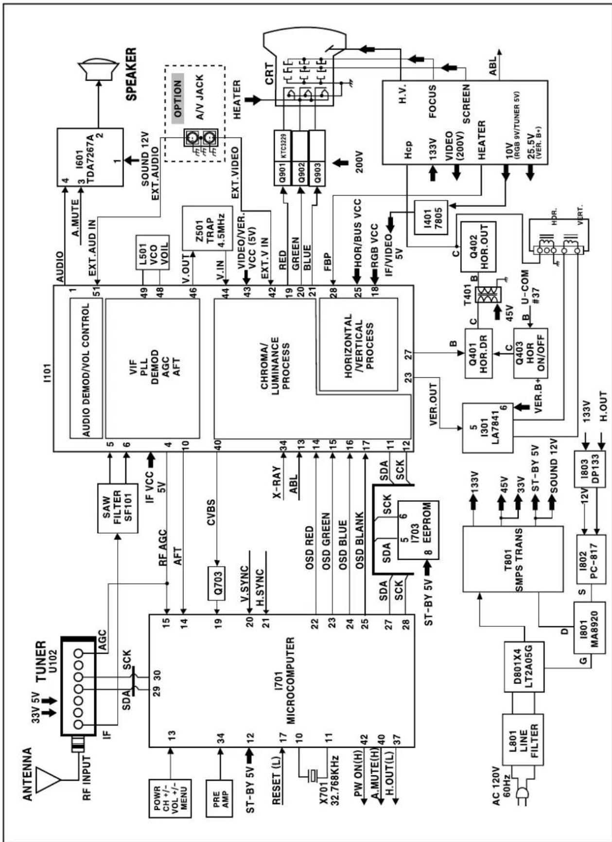
flowchart
graph TD
    A["ANTENNA"] --> B["TUNER U102"]
    B --> C["RF INPUT"]
    C --> D["33V 5V"]
    D --> E["AGC"]
    E --> F["SAW FILTER SF101"]
    F --> G["I101"]
    G --> H["AUDIO DEMOD/VOL CONTROL"]
    H --> I["VIF PLL DEMOD AGC AFT"]
    I --> J["L501 VCO VOIL"]
    J --> K["SOUND 12V EXT.AUDIO"]
    K --> L["SPEAKER"]
    M["POWER CH +/- VOL +/- MENU"] --> N["13"]
    N --> O["PIE AMP"]
    O --> P["PRE-5V"]
    P --> Q["ST-BY 5V"]
    Q --> R["RESET (L)"]
    R --> S["X701 32.768KHz"]
    S --> T["PW ON(H)"]
    T --> U["A.MUTE(H)"]
    U --> V["H.OUT(L)"]
    V --> W["I701 MICROCOMPUTER"]
    W --> X["I703 EEPROM"]
    X --> Y["ST-BY 5V"]
    Y --> Z["OSD RED"]
    Z --> AA["OSD GREEN"]
    AA --> AB["OSD BLUE"]
    AB --> AC["OSD BLANK"]
    AC --> AD["X-RAY ABL"]
    AD --> AE["CHROMA/LUMINANCE PROCESS"]
    AE --> AF["HORIZONTAL/VERTICAL PROCESS"]
    AF --> AG["VER.OUT"]
    AG --> AH["I401 7805"]
    AH --> AI["Hcp 133V VIDEO (200V) FOCUS SCREEN HEATER 10V (RGB 9V/TUNER 5V) 25.5V (VER. B+)"]
    AI --> AJ["ABL"]
    AK["AC 120V 60Hz"] --> AL["L801 LINE FILTER"]
    AL --> AM["D801X4 LT2A05G"]
    AM --> AN["T801 SMPS TRANS"]
    AN --> AO["I801 MA8920"]
    AO --> AP["S I802 PC-817"]
    AP --> AQ["I803 DP133"]
    AQ --> AR["I803 DP133"]
    AR --> AS["I803 DP133"]
    AS --> AT["I803 DP133"]
    AT --> AU["I803 DP133"]
    AU --> AV["I803 DP133"]
    AV --> AW["I803 DP133"]
    AW --> AX["I803 DP133"]
    AX --> AY["I803 DP133"]
    AY --> AZ["I803 DP133"]
    AZ --> BA["I803 DP133"]
    BA --> BB["I803 DP133"]
    BB --> BC["I803 DP133"]
    BC --> BD["I803 DP133"]
    BD --> BE["I803 DP133"]
    BE --> BF["I803 DP133"]
    BF --> BG["I803 DP133"]
    BG --> BH["I803 DP133"]
    BH --> BI["I803 DP133"]
    BI --> BJ["I803 DP133"]
    BJ --> BK["I803 DP133"]
    BK --> BL["I803 DP133"]
    BL --> BM["I803 DP133"]
    BM --> BN["I803 DP133"]
    BN --> BO["I803 DP133"]
    BO --> BP["I803 DP133"]
    BP --> BQ["I803 DP133"]
    BQ --> BR["I803 DP133"]
    BR --> BS["I803 DP133"]
    BS --> BT["I803 DP133"]
    BT --> BU["I803 DP133"]
    BU --> BV["I803 DP133"]
    BV --> BW["I803 DP133"]
    BW --> BX["I803 DP133"]
    BX --> BYI["I803 DP133"]
    BYI --> BZ["I803 DP133"]
    BZ --> CA["I803 DP133"]
    CA --> CBI["I803 DP133"]
    CBI --> CC["I803 DP133"]
    CC --> CDI["I803 DP133"]
    CDI --> CE["VER.B+"]
    CE --> CF["Q401 HOR.DR C T401 B U-COM #37"]
    CF --> CG["Q402 HOR.OUT"]
    CG --> CH["VER.V OUT"]
    CH --> CI["Q902 Q902 KTC3229"]
Alignment Instructions
1. SERVICE MODE ADJUSTMENTS
Follow the steps below whenever service adjustment is required. See Table-A and Table-B to determine if service adjustments are required.
1) How to enter the service mode using the user remote control.
- Turn the set on.
- Direct the remote control to the reception window of TV.
- Push buttons of remote control in sequence as follows.
1 --> MUTE --> DISPLAY --> MUTE
- Then, the screen will appear as follows.
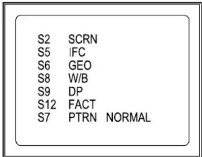
text_image
S2 SCRN S5 IFC S6 GEO S8 W/B S9 DP S12 FACT S7 PTRN NORMAL- Using the channel up or channel down button, select the item you wish to adjust.
(The color of selected item turns into the red.) - Press the volume up or down button to enter in the service mode you wish to adjust.
2) How to memorize the adjusted values in the service mode.
- Must press DISPLAY button the state which the screen is displaying each of service menus after all adjustments are completed each of all service menu.
Table-A : Adjust the values of service mode when a part is replaced.
| PART ADJUSTMENTREPLACED | NECESSARY UN | NOTES |
| I701(U-COM) | Data is stored in I703. | |
| I101(MAIN) | O | |
| I703(EEPROM) | O | |
| CRT Adjust items related to picture tube only. ( White Balance adjustment ) | ||
Table-B
| MODE | ADJUSTMENT ITEMS | DATA | REMARKS | |
| INITIAL RANGE | ||||
| S2 Screen Adjustment - - | ||||
| S5 | Auto RF AGC - - | |||
| Video Level (VIDEOL) 7 0 ~ 7 Must be set to 7 | ||||
| RF AGC Delay (RFAGCD) | * | 0 ~ 63 Align RF AGC threshold | ||
| FM Level (FM.LEV) 20 0 ~ 31 Must be set to 20 | ||||
| AGC Point 3.75 - Select AGC reference voltage | ||||
| FF CHK VCR | -- | VCR VCR/RF NOT USE | ||
| S6 | Horizontal Phase (H.PHASE) | * | 0 ~ 31 Align sync to flyback pulse, using internal cross pattern (S7) | |
| Vertical Position (V.POSI) | * | 0 ~ 63 Align vertical DC bias, using internal cross pattern (S7) | ||
| Vertical Size (V.SIZE) | * | 0 ~ 127 | Align vertical amplitude, using internal cross pattern (S7) | |
| Vertical Linearity | NO | 0 ~ 31 | (Must be set to 16) | |
| Vertical S-Correction (V SC) | 0 | 0 ~ 31 | Must be set to 6 | |
| No Sd Off | YES | - | (Automatically turn off in 15min for no received signal) | |
| 60 ~ 50 Hz | 4 | 0 ~ 31 | ||
| 60 ~ 50 Hz | 22 0 ~ 63 | |||
| 60 ~ 50 Hz | 0 0 ~ 127 | |||
| 60 ~ 50 Hz | 3 | 0 ~ 31 | ||
| S7 | Internal Black | - | - | Display internal BLACK pattern |
| Internal 100% White | - | - | Display internal 100% WHITE | |
| Internal 60% White | - | - | Display internal 60% WHITE | |
| Internal Cross Pattern | - | - | Display internal CROSS pattern | |
| S8 | Red Drive (RD) | * | 0 ~ 127 Align RED OUT AC level | |
| Green Drive (GD) | 14 0 ~ 15 Must be set to 10 | |||
| Blue Drive (BD) | * | 0 ~ 127 Align BLUE OUT AC level | ||
| Red Bias (RB) | * | 0 ~ 255 Align RED OUT DC level | ||
| Green Bias (GB) | * | 0 ~ 255 Align GREEN OUT DC level | ||
| Blue Bias (BB) | * | 0 ~ 255 Align BLUE OUT DC level | ||
| S9 | Subbrightness | * | 0 ~ 127 Align common RGB DC level | |
| Contrast | 27 0 ~ 27 | |||
| Tint | 35 0 ~ 27 | |||
| Color | 35 0 ~ 27 | |||
| S12 | Forwarding Mode | - | Factory Initialization | |
* indicates the items with different settings each of sets
2. ASSEMBLY ADJUSTMENTS
1) SCREEN ADJUSTMENT (S2)
- Enter the service mode and select service adjustment S2.
- You can see the one horizontal line on the screen.
- Adjust the Screen Control Volume (located on FBT) so that the horizontal line onscreen may be disappeared.
- Press the volume up or down button to exit in the screen adjustment mode.
NOTE
IN THE SCREEN ADJUSTMENT MODE, DONT PRESS OTHER BUTTONS EXCEPT VOLUME UP OR DOWN BUTTON.
2) FOCUS ADJUSTMENT
- Turn is a local station and adjust the Focus Control knob (located on FBT) for best picture details at hight condition.
3) RF AGC DELAY ADJUSTMENT (S5)
- Receive a good local channel.
- Enter the service mode and select service adjustment S5.
- You can see the OSD as shown in below.
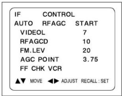
text_image
IF CONTROL AUTO RFAGC START VIDEOL 7 RFAGCD 10 FM.LEV 20 AGC POINT 3.75 FF CHK VCR ▲▼ MOVE ◀▶ ADJUST RECALL : SET- Select RFAGCD item, press the volume up or down button until noise or beat in picture disappears.
- Press the DISPLAY button to memorize the data.
4) GEOMETRIC ADJUSTMENTS (S6)
- Enter the service mode and select service adjustment S7.
- Whenever you select the "S7" using the volume up or down button, the screen is changing like this.

flowchart
graph LR
    A["NORMAL"] --> B["BLACK"]
    B --> C["WHITE100"]
    C --> D["WHITE60"]
    D --> E["CROSS"]
- Using the volume up or down button, select internal cross pattern.
- Select service adjustment S6
- You can see the OSD as shown in below.
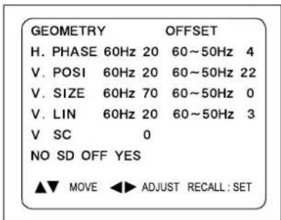
text_image
GEOMETRY OFFSET H. PHASE 60Hz 20 60~50Hz 4 V. POSI 60Hz 20 60~50Hz 22 V. SIZE 60Hz 70 60~50Hz 0 V. LIN 60Hz 20 60~50Hz 3 V SC 0 NO SD OFF YES ▲▼ MOVE ◀▶ ADJUST RECALL: SET4-1. Horizontal Position Adjustment
- Select H.PHASE item, adjust H.PHASE data value to obtain proper horizontal centering of the internal cross pattern at the left and right of the screen.
4-2. Vertical Position Adjustment
- Select V.POSI item, adjust V.POSI data value to center the raster properly on the screen.
4-3. Vertical Size Adjustment
- Select "V.SIZE" item, adjust "V.SIZE" data value to proper vertical size as follows.
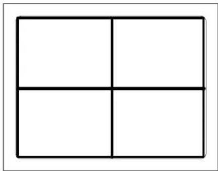
natural_image
Simple geometric diagram of a 2x2 grid with four equal squares (no text or symbols)5) WHITE BALANCE ADJUSTMENT (S8)
- Receive a good local channel.
- Enter the service mode and select service adjustment S8.
- You can see the OSD as shown in below.
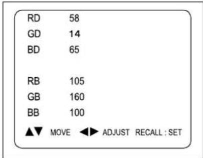
text_image
RD 58 GD 14 BD 65 RB 105 GB 160 BB 100 ▲▼ MOVE ◀► ADJUST RECALL : SET- Using volume up or volume down, adjust service adjustment data of RD/GD/BD and RB/GB/BB until a good gray scale with normal whites is obtained. ALIGNMENT INSTRUCTIONS
- Press the DISPLAY button to memorize the data.
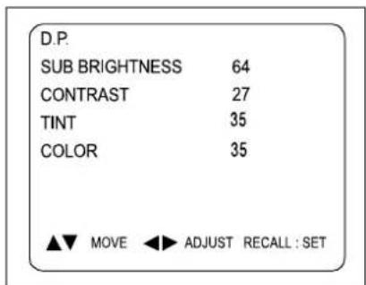
6) DIGITAL PRESET (D.P) ADJUSTMENTS (S9) SUBBRIGHTNESS ADJUSTMENT
- Receive a good local channel.
- Enter the service mode and select service adjustment S9.
- You can see the OSD as shown in below.
text_image
D.P. SUB BRIGHTNESS 64 CONTRAST 27 TINT 35 COLOR 35 ▲▼ MOVE ◀▶ ADJUST RECALL : SETAlignment Instructions
- Select Subbrightness item, adjust Subbrightness data value to obtain normal brightness level.
- Press the DISPLAY button to memorize the data.
CONTRAST
- Fixed value = 27
TINT
- Fixed value = 35
COLOR
- Fixed value = 25
- If you select the S12, then the set becomes factory outgoing status.
- You can see the OSD "outgoing OK"
SCHEMATIC DIAGRAM
SCHEMATIC DIAGRAM
CM-003
(1-30 MODEL)
274-12650 (2005.01.2)
5年4月1日(2013)6月1日
natural_image
Technical line drawing of a mechanical component with labeled parts (19 and 18), no readable text or symbols present.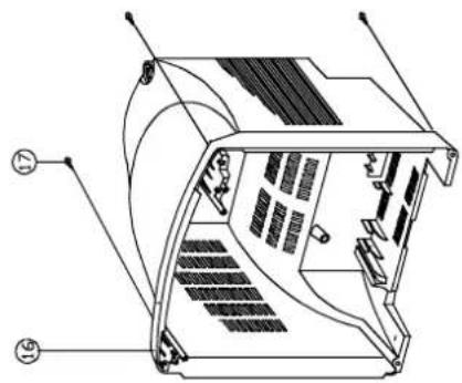
natural_image
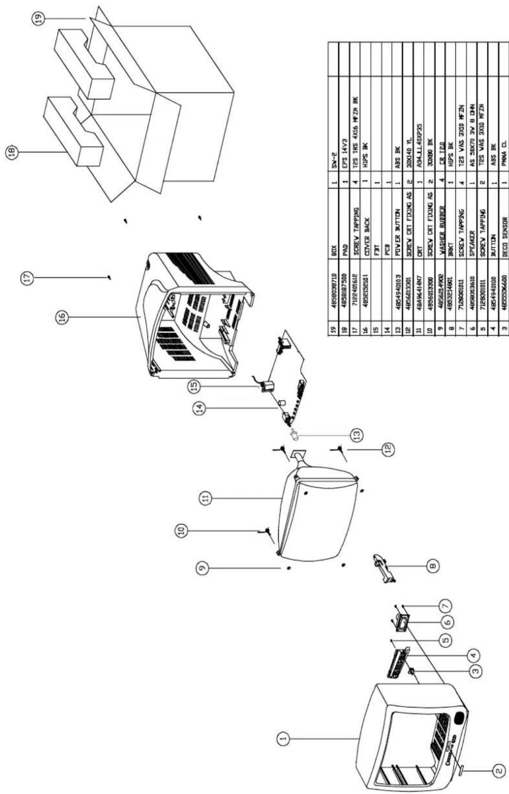
Technical line drawing of a mechanical device with labeled components (no text or symbols present)| 19 | 4858186700 | PAD | EPS 14V1 | ||
| 18 | 485803871D | BOX | 1 | SV=2 | |
| 17 | 7122401612 | SCREW TAPPING | 1 | T2S TRS 4X14 MFZN BK | |
| 16 | 4852151401 | COVER BACK | 4 | HIPS BK | |
| 15 | PCB | 1 | |||
| 14 | 4854939103 | POWER BUTTON | 1 | ABS BK | |
| 13 | 4856013351 | SCREW CRT FIXING AS | 2 | 2SX140 YL | |
| 12 | CRT | 1 | |||
| 11 | 4856013350 | SCREW CRT FIXING AS | 2 | 2SX80 BK | |
| 10 | 4856214902 | VASHER RUBBER | 4 | CR T2.0 | |
| 9 | 4857620401 | INSU PLATE | 1 | PVC+MICA A=76 | |
| 8 | 4853214801 | HOLDER BRKT | 2 | HIPS BK | |
| 7 | 7128301011 | SCREW TAPPING | 2 | T2S WAS3X10MFZN | |
| 6 | 4858313610 | SPEAKER | 1 | AS 50X70 3W JOHN | |
| 5 | 485493910E | BUTTON | 1 | ABS BK | |
| 4 | 4855536001 | DECO SENSOR | 1 | PMMA CL | |
| 3 | 4853214800 | BRKT PCB | 1 | FR HIPS | |
| 2 | 4852067201 | FRONT MASK | 1 | HIPS BK | |
| 1 | 48556136SS | MARK BRAND | 1 | SILVER ETGING IIIA-UTTING | |
| No | PART CORD | PART NAME | G*Y | MATERIAL | REMARKS |
text_image
Technical diagram of a device with numbered parts, likely an electrical or mechanical assembly, showing internal components and wiring.2. DTH-20V1FSN
text_image
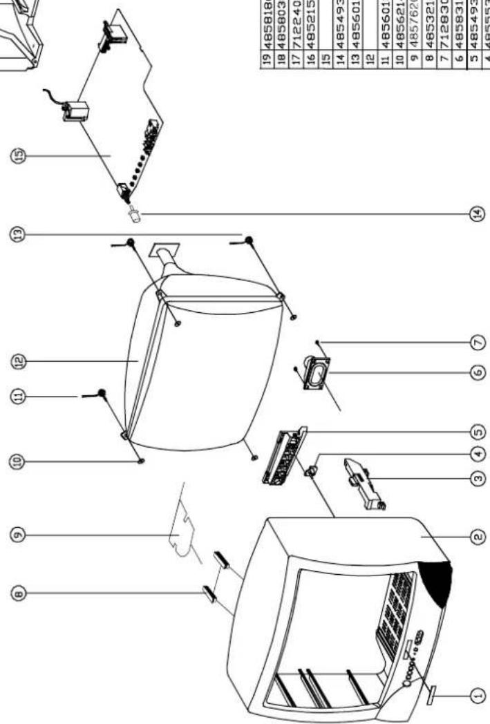
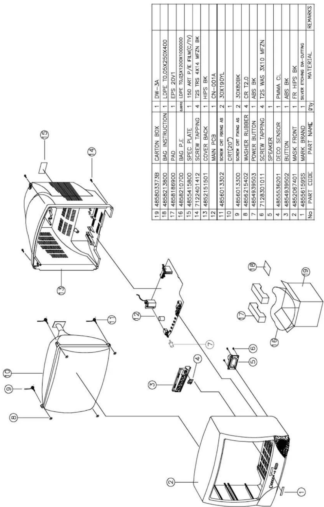
19 485803373B CARTON BOX 1 DW-3A 18 4858213800 BAG INSTRUCTION 1 LDPE T0.05X250X400 17 4858186900 PAD 1 EPS 20V1 16 4858210700 BAG P.E 0.0010 LDPE T0.03X1200X1000000 15 4855415800 SPEC PLATE 1 150 ART P/E FILM(C/TV) 14 7122401412 SCREW TAPPING 4 T2S TRS 4X14 MFZN BK 13 4852151501 COVER BACK 1 HIPS BK 12 MAIN PCB 1 CN-001A 11 4856013302 SCREW CRT FIXING AS 2 30X190YL 10 CRT(20") 1 9 4856013300 SCREW CRT FIXING AS 2 30X80BK 8 4856215402 WASHER RUBBER 4 CR T2.0 7 4854939503 POWER BUTTON 1 ABS BK 6 7128301011 SCREW TAPPING 4 T2S WAS 3X10 MFZN 5 SPEAKER 1 4 4855536201 DECO SENSOR 1 PMMA CL 3 4854939502 BUTTON 1 ABS BK 2 4852067401 MASK FRONT 1 FR HIPS BK 1 48556159SS MARK BRAND 1 SILVER ETCHING DIA-CUTTING No PART CODE PART NAME 0'ty MATERIAL REMARKS3. DTH-14V3FSN
| 19 | 4856036710 | BOX | 1 | SW-2 | |
| 19 | 4856887500 | PAD | 1 | EPS 14V3 | |
| 17 | 7122401612 | SCREW TAPPING | 4 | T2S TK5 AX16 MFZN BK | |
| 16 | 4856198101 | COVER BACK | 1 | HOPS BK | |
| 15 | FBIT | 1 | |||
| 14 | PCB | 1 | |||
| 13 | 4854940013 | POWER BUTTON | 1 | ABS BK | |
| 12 | 4856013301 | SCREW CRT FIXING AS | 2 | 3DX140 YL | |
| 11 | 48496414N7 | CRT | 1 | A34_1L 4DXP25 | |
| 10 | 4856013300 | SCREW CRT FIXING AS | 2 | 3DX80 BK | |
| 9 | 4856214902 | VASHER RUBBER | 4 | CR 120 | |
| 8 | 4853214801 | BRKT | 1 | HIPS BK | |
| 7 | 7128020111 | SCREW TAPPING | 4 | T2S VAS 3X10 MFZN | |
| 6 | 4856033610 | SPEAKER | 1 | AS 3DX70 3V B DHN | |
| 5 | 7128020111 | SCREW TAPPING | 2 | T2S VAS 3X10 MFZN | |
| 4 | 4854940100 | BUTTON | 1 | ABS BK | |
| 3 | 4855536600 | DECO SENSOR | 1 | PMNA CL | |
| 2 | 48556136SS | MARK BRAND | 1 | SILVER ETICHING DUA-GUTTING | |
| 1 | 4852056300 | FRONT MASK | 1 | FR HOPS BK | |
| No | PART CODE | PART NAME | Qty | MATERIAL | REMARKS |
4. DTH-20V3FSN
text_image
Technical diagram of a refrigerator with numbered parts and component labels, including battery, door, and control buttons.- DTH-14V4FSN
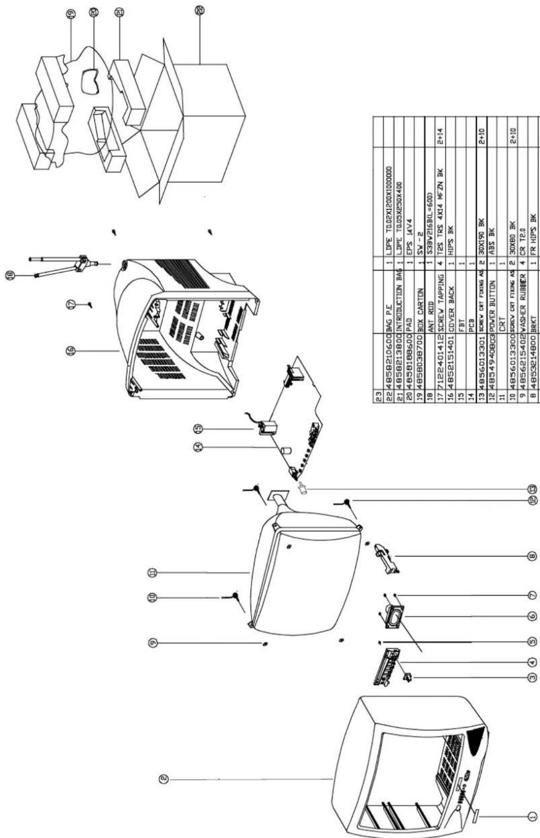
text_image
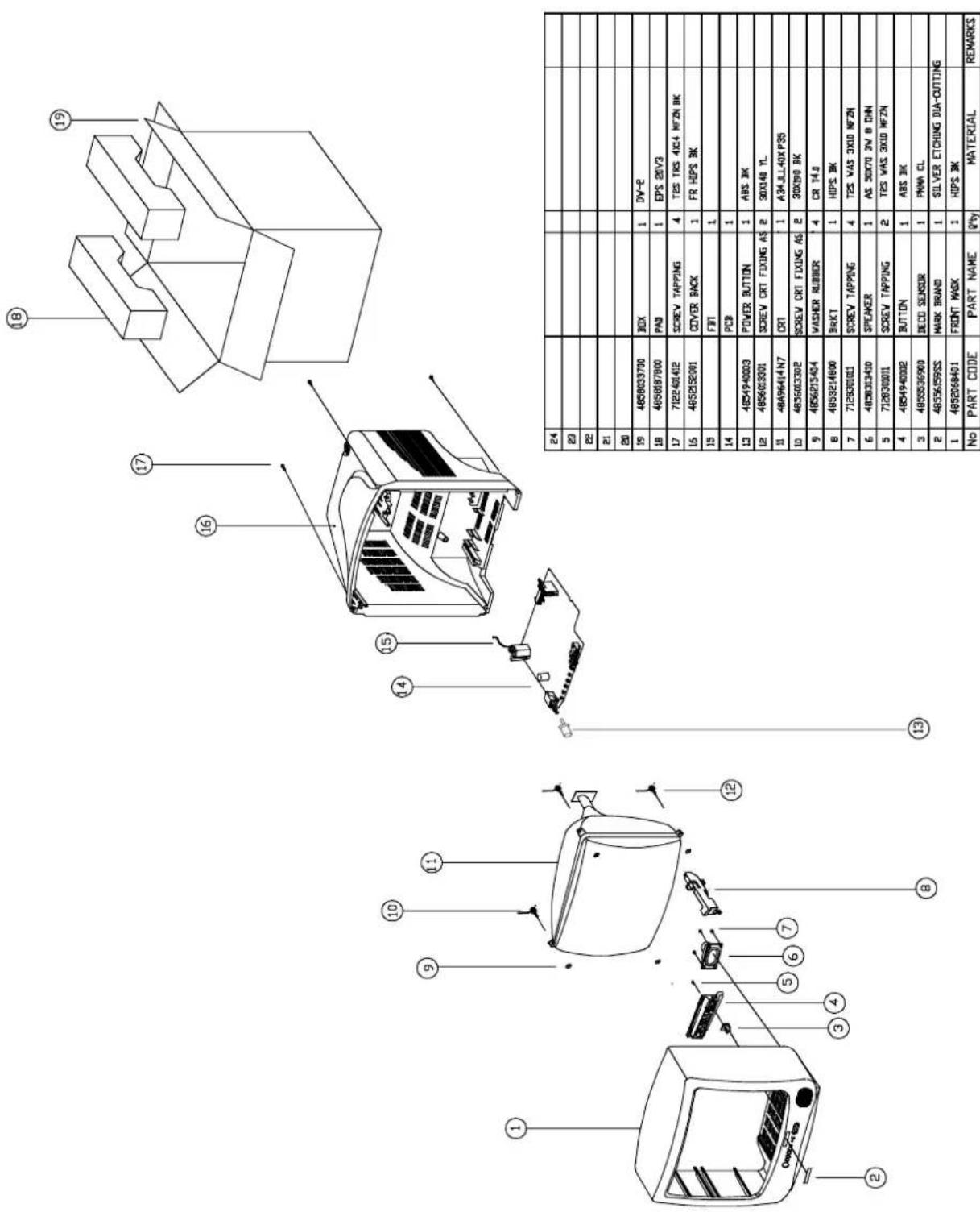
Technical diagram of a device with exploded view and component labels in Chinese, including parts like BAG P.E., S3BV216RL, and power button.| 23 | |||||
| 22 | 4858210600 | BAG P.E | 1 | LDPE T0.02X1200X1000000 | |
| 21 | 4858213800 | INTRODUCTION BAG | 1 | LDPE T0.03X230X400 | |
| 20 | 4858188600 | PAD | 1 | EPS 14V4 | |
| 19 | 4858038700 | BOX CARTON | 1 | SW - 2 | |
| 18 | ANT ROD | 1 | S39W216R(=600) | ||
| 17 | 7122401412 | SCREW TAPPING | 4 | T2S TRS 4X14 WFZN BK | 2+14 |
| 16 | 4852151401 | COVER BACK | 1 | HIPS BK | |
| 15 | FBT | 1 | |||
| 14 | PCB | 1 | |||
| 13 | 4856013301 | SCREW CRT FIXING AS | 2 | 30X190 BK | 2+10 |
| 12 | 4854940803 | POWER BUTTON | 1 | ABS BK | |
| 11 | CRT | 1 | |||
| 10 | 4856013300 | SCREW CRT FIXING AS | 2 | 30X80 BK | 2+10 |
| 9 | 4856215402 | WASHER RUBBER | 4 | CR TE.0 | |
| 8 | 4853214800 | BRKT | 1 | FR HIPS BK | |
| 7 | 7128301212 | SCREW TAPPING | 2 | T2S WAS 3X12MFZN BK | 2+6 |
| 6 | 4858313610 | SPEAKER | 1 | AS 50X70 3W BUHN | |
| 5 | 7128301212 | SCREW TAPPING | 2 | T2S WAS 3X12MFZN BK | 2+4 |
| 4 | 4854940802 | BUTTON | 1 | ABS BK | |
| 3 | 48555537401 | DECO SENSOR | 1 | PMMA CL | |
| 2 | 4852069301 | MASK FRONT | 1 | HIPS BK | |
| 1 | 4855613655 | MARK BRAND | 1 | SILVER ETCHING DIA-CUTTING | |
| No | PART CORD | PART NAME | Q'ty | MATERIAL | REMARKS |
- DTH-20V4FSN
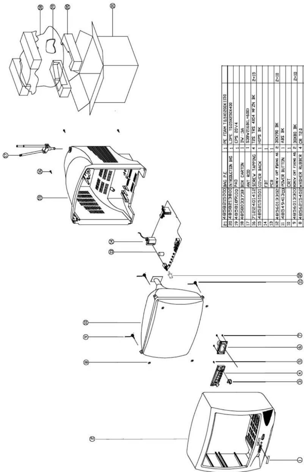
text_image
Technical diagram of a device with exploded view and component labels in Chinese, including parts like engine, battery pack, and control buttons.| 21 | 48580215000 | BAG P.E | 1 | PE FOAM T0.5X1200X1150 | |
| 20 | 48580213800 | INTRODUCTION BAG | 1 | LDPE T0.05X250X400 | |
| 19 | 48580169100 | PAD | 1 | EPS 20V4 | |
| 18 | 485803373B | BOX CARTON | 1 | DW-3A | |
| 17 | ANT ROD | 1 | S3BV216BL=600D | ||
| 16 | 7122401412 | SCREW TAPPING | 4 | T2S TRS 4X14 MFZN BK | 2+15 |
| 15 | 4852151501 | COVER BACK | 1 | HIPS BK | |
| 14 | FBT | 1 | |||
| 13 | PCB | 1 | |||
| 12 | 4856013302 | SCREW CRT FIXING AS | 2 | 30X190 BK | 2+10 |
| 11 | 4854941303 | POWER BUTTON | 1 | ABS BK | |
| 10 | CRT | 1 | |||
| 9 | 4856013300 | SCREW CRT FIXING AS | 2 | 30X80 BK | 2+10 |
| 8 | 4856215402 | WASHER RUBBER | 4 | CR T2.0 | |
| 7 | 7128301011 | SCREW TAPPING | 2 | T2S WAS 3X10MFZN BK | 2+6 |
| 6 | 4858313610 | SPEAKER | 1 | AS 50X70 3W BDHN | |
| 5 | 7128301212 | SCREW TAPPING | 2 | T2S WAS 3X12MFZN BK | 2+4 |
| 4 | 4854941302 | BUTTON | 1 | ABS BK | |
| 3 | 4855537401 | DECO SENSOR | 1 | PMA CL | |
| 2 | 4852069001 | MASK FRONT | 1 | HIPS BK | |
| 1 | 48556159SS | MARK BRAND | 1 | SILVER ETCHING DIA-CUTTING | |
| No | PART CORD | PART NAME | 2*Y | MATERIAL | REMARKS |
Service Parts List
CAUTION
“®” Parts recommended for stock.
“⚠” Safety critical component, Replace only with genuine Daewoo safety part.
LOC PART CODE PART NAME DESCRIPTION
| ■ | △® | 48B4343A01 | TRANSMITTER REMOCON | R-43A01 (AA) |
| ■ | ▲ | PTACPWH403 ACCESSORY AS DTH-14V4FS |
| 00010 | 4850A02510 ANT | ROD S3BW216B (L=600 MM) | |
| 00030 | 4850Q00810 BATT | TERY R6P/LN | |
| 00040 | 4850A00650 TRAN | NS ANT MATCHING YSC-T | -07 BR |
| 00050 | 48586003S1 MAN | UAL INSTRUCTION SPAIN | |
| M821 | 4858213800 | BAG INSTRUCTION | L.D.P.E T0.05X250X400 |
| ■ | PTBCSHH427 | COVER BACK AS | DTH-14V1FS |
| M211 | 4852151401 COVER BACK HIPS BK | |
| M211A | 4857817640 CLOTH BLACK FELT | 100X20X0.7 |
| M541 | 4855415800 SPEC PLATE 150ART P/E FILM (C/TV) | |
| ■ | ⚠️ | PTPKCPH427 | PACKING AS | DTH-14V1FS |
| 10 | 6520010100 STAPLE PIN 18MM JDO | ||
| M801 | 4858038700 BOX | CARTON SW-2 DTQ-1463FW | |
| M811 | 4858186700 PAD | EPS 14V1 | |
| M821 | 4858210600 | BAG P.E | L.D.P.E T0.03X1000X900 |
| ■ | 58G0000084 COIL DEGAUSSING | DC-1450 |
| ■ | 48519A4710 CRT GROUND NET | 1401S-1015-1P |
| PTCACAH529 | CABINET AS | DTH-14V1FSN |
| ® CRT1 | PTRTPWH529 | CRT AS | DTH-14V1FSN | |
| V01 | 58D0000082 | COIL DY | ODY-M1489 | |
| V02 | 2233030001 PAINT LOCK 760G | |||
| V03 | 2TC26019BE | TAPE CLOTH | 19X30 BEIGE | |
| V04 | 2224050026 BOND SILICON RTV 122 CARTRIDGE | |||
| V05 | 4850PM001- | MAGNET CP | NY-225 (MINI NECK) | |
| V06 | 48A96R004- | RUBBER WEDGE | HMR 28 SR (|0X54) | |
| V901 | 48A96314C5 CRT | BARE A34AGT13X (R) | ||
| M191 | 4851931802 | BUTTON CTRL | 4939102+5536001 | |
| M191A | 7178301011 SCREW TAPPTITE TT2 WAS 3X10 MFZN | |||
| M201A | 4856013350 SCREW CRT FIXING 25X80 BK | |||
| M201B | 4856215402 | WASHER RUBBER | CR T2.0 | |
| M201C | 4856013351 SCREW CRT FIXING 25X140 YL | |||
| M211A | 7172401412 SCREW TAPPTITE TT2 TRS 4X14 MFZN BK | |||
| M321 | 4853214800 BRKT FR HIPS BK | |||
| M491 | 4854939103 BUTTON ABS BK | |||
| M561 | 48556136SS MARK BRAND | SILVER ETCHING DIACUTTIN | ||
| M681 | 4856812001 TIE CABLE NYLON66 DA100 | |||
| SP01A | 7178301011 SCREW TAPPTITE TT2 WAS 3X10 MFZN | |||
| ■ | PTFMSJH427 | MASK FRONT AS | DTH-14V1FS |
| M201 | 4852067201 | MASK FRONT | HIPS | BK |
| ZZ202 PTSPPWH407 | SPEAKER AS | DTQ-14J4FC |
| PA601 | 4850703S50 CONNECTOR | YH025-03-35098+ULW=200 |
| ® SP01 | 4858314010 SPEAKER | SP-5070F01 3W 8 OHM |
LOC PART CODE PART NAME DESCRIPTION
■△® PTMPMSH529 PCB MAIN MANUAL AS DTH-14V1FSN
| C101 | CEXF1H109V | C ELECTRO | 50V RSS 1MF (5X11) TP |
| C102 | CEXF1C101V | C ELECTRO | 16V RSS 100MF (6.3X11) TP |
| C103 | CEXF1H229V | C ELECTRO | 50V RSS 2.2MF (5X11) TP |
| C104 | CMXM2A333J | C MYLAR 100V 0.033MF J (TP) | |
| C105 | CEXF1C471V | C ELECTRO | 16V RSS 470MF (10X12.5)TP |
| C106 | CEXF1H109V | C ELECTRO | 50V RSS 1MF (5X11) TP |
| C107 | CEXF1H228V | C ELECTRO | 50V RSS 0.22MF (5X11) TP |
| C109 | CCZF1H103Z | C CERA | 50V F 0.01MF Z |
| C110 | CCZF1H103Z | C CERA | 50V F 0.01MF Z |
| C111 | CCZF1H103Z | C CERA | 50V F 0.01MF Z |
| C112 | CCZF1H103Z | C CERA | 50V F 0.01MF Z |
| C113 | CCZF1H103Z | C CERA | 50V F 0.01MF Z |
| C301 | CMXM2A103J | C MYLAR 100V 0.01MF J (TP) | |
| C302 | CEXF1H479V | C ELECTRO | 50V RSS 4.7MF (5X11) TP |
| C303 | CEXF1H100V | C ELECTRO | 50V RSS 10MF (5X11) TP |
| C305 | CEXF1H101V | C ELECTRO | 50V RSS 100MF (8X11.5) TP |
| C307 | CXSL2H100D | C CERA | 500V SL 10PF D (TAPPING) |
| C308 | CMXM2A104J | C MYLAR 100V 0.1MF J (TP) | |
| C310 | CEXF1E102C | C ELECTRO | 25V RUS 1000MF (13X20) TP |
| C311 | CEXD1H229Q | C ELECTRO | 50V RT 2.2MF (6.3X11) TP |
| C401 | CCXB2H102K | C CERA | 500V B 1000PF K (TAPPING) |
| C403 | CCYB2H103K | C CERA | 500V B 0.01MF K |
| C404 | CMYH3C722J | C MYLAR 1.6KV BUP 7200 PF J | |
| C405 | CEXF2C109V | C ELECTRO | 160V RSS 1MF (6.3X11) TP |
| C406 | CMYE2D514J | C MYLAR 200V PU 0.51MF J | |
| C410 | CEXF2E100V | C ELECTRO | 250V RSS 10MF (10X20) TP |
| C411 | CEXF1H100V | C ELECTRO | 50V RSS 10MF (5X11) TP |
| C413 | CCXB2H102K | C CERA | 500V B 1000PF K (TAPPING) |
| C414 | CEXF1V471V | C ELECTRO | 35V RSS 470MF (10X20) TP |
| C415 | CEXF1C102V | C ELECTRO | 16V RSS 1000MF (10X20) TP |
| C418 | CMXM2A104J | C MYLAR 100V 0.1MF J (TP) | |
| C419 | CBZF1H104Z | C CERA SEMI 50V F 0.1MF Z | |
| C451 | CEXF1C101V | C ELECTRO | 16V RSS 100MF (6.3X11) TP |
| C452 | CEXF1C221V | C ELECTRO | 16V RSS 220MF (8X11.5) TP |
| C453 | CEXF1C101V | C ELECTRO | 16V RSS 100MF (6.3X11) TP |
| C501 | CMXL1J105J | C MYLAR 63V MEU 1MF J | |
| C502 | CEXF1C471V | C ELECTRO | 16V RSS 470MF (10X12.5)TP |
| C507 | CMXM2A224J | C MYLAR 100V 0.22MF J | |
| C508 | CMXM2A224J | C MYLAR 100V 0.22MF J | |
| C509 | CEXF1H229V | C ELECTRO | 50V RSS 2.2MF (5X11) TP |
| C510 | CEXF1C471V | C ELECTRO | 16V RSS 470MF (10X12.5)TP |
| C511 | CMXM2A333J | C MYLAR 100V 0.033MF J (TP) | |
| LOC | PART CODE | PART NAME | DESCRIPTION |
| C512 | CEXF1H478V C ELECTRO | 50V RSS 0.47MF (5X11) TP | |
| C513 | CEXF1H109V C ELECTRO 50V RSS 1MF (5X11) TP | ||
| C514 | CEXF1C471V C ELECTRO | 16V RSS 470MF (10X12.5)TP | |
| C515 | CEXD1H229F | C ELECTRO | 50V RND 2.2MF (5X11) TP |
| C516 | CEXF1H478V | C ELECTRO | 50V RSS 0.47MF (5X11) TP |
| C518 | CEXF1H478V | C ELECTRO | 50V RSS 0.47MF (5X11) TP |
| C520 | CEXF1H109V C ELECTRO | 50V | RSS 1MF (5X11) TP |
| C521 | CEXF1H100V C ELECTRO | 50V | RSS 10MF (5X11) TP |
| C523 | CEXF1H470V C ELECTRO | 50V RSS 47MF (6.3X11) TP | |
| C524 | CEXF1H100V C ELECTRO | 50V | RSS 10MF (5X11) TP |
| C525 | CEXF1H109V C ELECTRO | 50V | RSS 1MF (5X11) TP |
| C526 | CCZB1H391K C CERA 50V B 390PF K (AXIAL) | ||
| C527 | CCZB1H102K C CERA 50V B 1000PF K (AXIAL) | ||
| C528 | CCZB1H101K C CERA 50V B 100PF K (AXIAL) | ||
| C529 | CCZB1H101K C CERA 50V B 100PF K (AXIAL) | ||
| C530 | CXCH1H809D C CERA | 50V | CH 8PF D (TAPPING) |
| C532 | CCZF1H103Z C CERA | 50V | F 0.01MF Z |
| C533 | CZCH1H180J | C CERA | 50V CH 18PF J (AXIAL) |
| C534 | CCZF1H103Z C CERA | 50V | F 0.01MF Z |
| C535 | CCZF1H103Z C CERA | 50V | F 0.01MF Z |
| C536 | CCZF1H103Z C CERA | 50V | F 0.01MF Z |
| C537 | CCZB1H181K C CERA | 50V | B 180PF K (AXIAL) |
| C538 | CCZF1H103Z C CERA | 50V | F 0.01MF Z |
| C539 | CCZF1H103Z C CERA | 50V | F 0.01MF Z |
| C540 | CBZF1H104Z | C CERA SEMI 50V F 0.1MF Z | |
| C541 | CBZF1H104Z | C CERA SEMI 50V F 0.1MF Z | |
| C542 | CBZF1H104Z | C CERA SEMI 50V F 0.1MF Z | |
| C548 | CCXB1H152K C CERA | 50V B 1500PF K (TAPPING) | |
| C555 | CEXF1H109V C ELECTRO | 50V | RSS 1MF (5X11) TP |
| C566 | CEXF1H100V C ELECTRO | 50V | RSS 10MF (5X11) TP |
| C601 | CMXM2A103J C MYLAR 100V 0.01MF J (TP) | ||
| C602 | CEXF1C102V C ELECTRO | 16V RSS 1000MF (10X20) TP | |
| C603 | CEXF1H108V | C ELECTRO | 50V RSS 0.1MF (5X11) TP |
| C606 | CMXM2A123J C MYLAR 100V 0.012MF J (TP) | ||
| C607 | CCZB1H101K C CERA | 50V | B 100PF K (AXIAL) |
| C611 | CEXF1H100V C ELECTRO | 50V | RSS 10MF (5X11) TP |
| C701 | CEXF1H470V C ELECTRO | 50V RSS 47MF (6.3X11) TP | |
| C702 | CEXF1C221V | C ELECTRO | 16V RSS 220MF (8X11.5) TP |
| C703 | CEXF1H109V C ELECTRO | 50V | RSS 1MF (5X11) TP |
| C704 | CEXF1H229V C ELECTRO | 50V RSS 2.2MF (5X11) TP | |
| C705 | CEXF1H109V C ELECTRO | 50V | RSS 1MF (5X11) TP |
| C706 | CEXF1C101V C ELECTRO | 16V RSS 100MF (6.3X11) TP | |
| C707 | CMXM2A104J C MYLAR 100V 0.1MF J (TP) | ||
| C708 | CEXF1H109V C ELECTRO | 50V | RSS 1MF (5X11) TP |
| C709 | CZCH1H180J | C CERA | 50V CH 18PF J (AXIAL) |
| C710 | CZCH1H180J | C CERA | 50V CH 18PF J (AXIAL) |
| C711 | CCZF1H103Z C CERA | 50V | F 0.01MF Z |
| C712 | CCZF1H103Z C CERA | 50V | F 0.01MF Z |
| C713 | CCZB1H221K C CERA | 50V | B 220PF K (AXIAL) |
| LOC | PART CODE | PART NAME | DESCRIPTION |
| C714 | CMXM2A333J C MYLAR 100V 0.033MF J (TP) | ||
| C721 | CZSL1H470J C CERA 50V SL 47PF J (AXIAL) | ||
| C723 | CCZB1H101K C CERA 50V B 100PF K (AXIAL) | ||
| C724 | CCZF1H103Z C CERA 50V F 0.01MF Z | ||
| C725 | CCZF1H103Z C CERA 50V F 0.01MF Z | ||
| C801 | CL1UC3104M C LINE ACROSS | WORLD AC250V 0.1UF M R.47 | |
| C802 | CCXB2H472K C CERA 500V B 4700PF K (TAPPING) | ||
| C803 | CCXB2H472K C CERA 500V B 4700PF K (TAPPING) | ||
| C804 | CEYN2W151P C ELECTRO 450V LHS 150MF (25X40) | ||
| C805 | CMYH3C222J C MYLAR 1.6KV BUP 2200PF J | ||
| C806 | CMXM2A122J C MYLAR 100V 1200PF J (TP) | ||
| C807 | CMXM2A102J C MYLAR 100V 1000PF J (TP) | ||
| C812 | CEXF1C102V C ELECTRO | 16V RSS 1000MF (10X20) TP | |
| C813 | CBXB3D471K C CERA SEMI 2KV BL(N) 470PF K (T) | ||
| C814 | CEXF2C101V C ELECTRO | 160V RSS 100MF (16X25) TP | |
| C815 | CEXF2A100V C ELECTRO 100V RSS 10MF (6.3 X11) TP | ||
| C818 | CEXF1C101V C ELECTRO 16V RSS 100MF (6.3 X11) TP | ||
| C819 | CEXF1H479V C ELECTRO 50V RSS 4.7MF (5X11) TP | ||
| C820 | CEXF2C101V C ELECTRO 160V RSS 100MF (16X25) TP | ||
| C831 | CMXM2A104J C MYLAR 100V 0.1MF J (TP) | ||
| C887 | CH1BEE472M C CERA AC U/C/V 2.5KV 4700PF TP | ||
| C888 | CH1BEE472M C CERA AC U/C/V 2.5KV 4700PF TP | ||
| C901 | CCZB1H331K C CERA 50V B 330PF K (AXIAL) | ||
| C902 | CCZB1H331K C CERA 50V B 330PF K (AXIAL) | ||
| C903 | CCZB1H102K C CERA 50V B 1000PF K (AXIAL) | ||
| C965 | CCXB3D102K C CERA | 2KV B 1000PF K (TAPPING) | |
| CA01 | CEXF1H100V C ELECTRO 50V RSS 10MF (5X11) TP | ||
| CA02 | CCZB1H102K C CERA 50V B 1000PF K (AXIAL) | ||
| D101 | DUZ33B---- | DIODE ZENER | UZ-33B |
| D301 | D1N4004S-- | DIODE | 1N4004S |
| ® D401 | D1N4937G-- | DIODE | 1N4937G (TAPPING) |
| D405 | D1N4937G-- | DIODE | 1N4937G (TAPPING) |
| D406 | D1N4937G-- | DIODE | 1N4937G (TAPPING) |
| D407 | D1N4937G-- | DIODE | 1N4937G (TAPPING) |
| D408 | D1N4937G-- | DIODE | 1N4937G (TAPPING) |
| D409 | D1N4148--- | DIODE | 1N4148 (TAPPING) |
| D501 | D1N4148--- | DIODE | 1N4148 (TAPPING) |
| D502 | D1N4148--- | DIODE | 1N4148 (TAPPING) |
| D503 | DUZ9R1BM-- DIODE ZENER UZ-9.1BM | ||
| D504 | D1N4148--- | DIODE | 1N4148 (TAPPING) |
| D505 | DUZ9R1BM-- DIODE ZENER UZ-9.1BM | ||
| D601 | DUZ5R6BM-- DIODE ZENER UZ-5.6BM | ||
| D701 | D1N4148--- | DIODE | 1N4148 (TAPPING) |
| D703 | DLH2PR---- | LED BLOCK | -LH-2P-R |
| D704 | DUZ3R9B--- | DIODE ZENER | UZ-3.9B |
| D757 | D1N4148--- | DIODE | 1N4148 (TAPPING) |
| ® D801 | DLT2A05G-- | DIODE | LT2A05G (TP) |
| D802 | DLT2A05G-- | DIODE | LT2A05G (TP) |
| D803 | DLT2A05G-- | DIODE | LT2A05G (TP) |
| D804 | DLT2A05G-- DIODE | LT2A05G (TP) | |
| D805 | D1N4937G-- DIODE | 1N4937G (TAPPING) | |
| ® D807 | DRGP15J--- DIODE | RGP15J | |
| D808 | D1N4937G-- DIODE | 1N4937G (TAPPING) | |
| D812 | DUZ5R6BM-- DIODE | ZENER UZ-5.6BM | |
| D813 | D1N4937G-- DIODE | 1N4937G (TAPPING) | |
| D822 | DZY160---- DIODE | ZENER ZY160 | |
| D831 | DUZ8R2BM-- DIODE | ZENER UZ-8.2B | |
| DA01 | D1N4148--- DIODE | 1N4148 (TAPPING) | |
| F801 | FSGB4022L FUSE | GLASS TUBE | SEMKO TL 4A 250V MF51 |
| F801A | 4857415001 CLIP | FUSE PFC5000-0702 | |
| F801B | 4857415001 CLIP | FUSE PFC5000-0702 | |
| I101 | LA76805-- IC MAIN | LA76805 | |
| ® I301 | 1LA7841--- | IC VERTICAL | LA7841 |
| I301A | 4857027101 | HEAT SINK | SPCC T1.0+SN |
| I301B | 7174300811 SCREW | TAPPTITE TT2 RND 3X8 | MFZN |
| I401 | 1K1A7805P1 | IC REGULATOR | KIA7805API |
| ® I601 | 1TDA7056A- | IC AUDIO | TDA7056A |
| I601A | 4857025400 HEAT | SINK A1050 | P-H24 T2.0 |
| I601B | 7174301011 SCREW | TAPPTITE TT2 RND 3X10 | MFZN |
| ® I701 | 1DW8632CM2 | IC MICOM | DW863228V-CM2(5P18) |
| ® I703 | 1AT24C04PC | IC MEMORY | AT24C04-10PC |
| ® I801 | 1MA8920--- | IC POWER | MA8920 |
| I801A | 4857015801 HEAT | SINK SPCC-SN T1.0 | |
| I801B | 7174301011 SCREW | TAPPTITE TT2 RND 3X10 | MFZN |
| I801C | 4853938501 BRKT | TR SBHG1-A T1.5 | |
| ® I802 | 1LTV817C-- | IC PHOTO COUPLER | LTV-817C |
| ® I803 | 1DP133---- | IC ERROR AMP | DP133 |
| IL701 | 1KRT30---- IC PREAMP | KRT30 | |
| JP02 | 4859109950 JACK | PIN BOARD PH-JB-9710A | |
| JP03 | 4859109150 JACK | PIN BOARD PH-JB-9615C | |
| L111 | 58C5580019 | COIL CHOKE TRF-9225 (0.55UH) | |
| L112 | 5CPZ220K02 COIL | PEAKING 22UH K (AXIAL 3.5MM) | |
| L501 | 58N0000042 | COIL VCO TRF-V008 | |
| L502 | 5CPZ470K04 COIL | PEAKING | 47UH 10.5MM K (LAL04TB) |
| L533 | 5CPZ150K02 COIL | PEAKING 15UH K (AXIAL 3.5MM) | |
| L601 | 5MC0000100 COIL | BEAD HC-3550 | |
| L701 | 5CPZ220K02 COIL | PEAKING 22UH K (AXIAL 3.5MM) | |
| L801 | 5PTLF106-- | FILTER LINE | TLF-106 |
| L802 | 5MC0000100 COIL | BEAD HC-3550 | |
| L805 | 58CX430599 | COIL CHOKE | AZ-9004Y 940K TP |
| L807 | 5MC0000100 COIL | BEAD HC-3550 | |
| L808 | 5MC0000100 COIL | BEAD HC-3550 | |
| L901 | 5CPX221J-- COIL | PEAKING 220UH J (RADIAL) | |
| P401 | 4859240020 CONN | WAFER YFW500-05 | |
| P601 | 485923162S CONN | WAFER YW025-03 (STICK) | |
| P602 | 485923162S CONN | WAFER YW025-03 (STICK) | |
| P801 | 4859242220 CONN | WAFER YFW800-02 | |
| PA501 | 4850708N11 | CONNECTOR | BIC-08T-25T+C-20T+ULW=300 |
| LOC | PART CODE | PART NAME | DESCRIPTION |
| ®PWC1 | 4859902910 | CORD POWER AS | KKP419C-BL102NG+TUBE=2100 |
| Q401 | TKSC2330Y- | TR | KSC2330Y (TP) |
| ®Q402 | TKSC5386-- | TR | KSC5386 R |
| Q403 | TKSC945CY- | TR | KSC 945C-Y (TAPPING) |
| Q601 | TKSC945CY- | TR | KSC 945C-Y (TAPPING) |
| Q602 | TKSC945CY- | TR | KSC 945C-Y (TAPPING) |
| Q603 | TKSC945CY- | TR | KSC 945C-Y (TAPPING) |
| Q701 | TKSC945CY- | TR | KSC 945C-Y (TAPPING) |
| Q702 | TKSC945CY- | TR | KSC 945C-Y (TAPPING) |
| Q703 | TKSC945CY- | TR | KSC 945C-Y (TAPPING) |
| Q704 | TKSA733CY- | TR | KSA733CY (TP) |
| Q804 | TKSA1013Y- TR | KSA1013Y (TP) | |
| Q805 | TKTC3205Y- TR | KTC3205Y (TP) | |
| Q807 | TKSC945CY- | TR | KSC 945C-Y (TAPPING) |
| Q831 | TKSC945CY- | TR | KSC 945C-Y (TAPPING) |
| ®Q901 | TKTC3229-- TR | KTC3229 | |
| Q902 | TKTC3229-- TR | KTC3229 | |
| Q903 | TKTC3229-- TR | KTC3229 | |
| Q911 | TKSA733CY- | TR | KSA733CY (TP) |
| QV01 | TKSC945CY- | TR | KSC 945C-Y (TAPPING) |
| R101 | RD-AZ682J- | R CARBON FILM | 1/6 6.8K OHM J |
| R103 | RD-AZ153J- | R CARBON FILM | 1/6 15K OHM J |
| R104 | RD-AZ104J- | R CARBON FILM | 1/6 100K OHM J |
| R105 | RD-AZ473J- | R CARBON FILM | 1/6 47K OHM J |
| R106 | RD-AZ473J- | R CARBON FILM | 1/6 47K OHM J |
| R107 | RD-AZ472J- | R CARBON FILM | 1/6 4.7K OHM J |
| R301 | RN01B471JS R MET | TAL FILM 1W 470 OHM J SMALL | |
| R302 | RN02B391JS R MET | TAL FILM 2W 390 OHM J SMALL | |
| R303 | RN02B129JS R MET | TAL FILM 2W 1.2 OHM J SMALL | |
| R304 | RD-AZ682J- | R CARBON FILM | 1/6 6.8K OHM J |
| R305 | RN01B331JS R MET | TAL FILM 1W 330 OHM J SMALL | |
| R306 | RD-AZ273J- | R CARBON FILM | 1/6 27K OHM J |
| R307 | RD-AZ333J- | R CARBON FILM | 1/6 33K OHM J |
| R308 | RD-AZ222J- | R CARBON FILM | 1/6 2.2K OHM J |
| R309 | RD-AZ113J- | R CARBON FILM | 1/6 11K OHM J |
| R352 | RN-4Z1603F | R METAL FILM | 1/4 160K OHM F |
| R353 | RN-4Z1502F | R METAL FILM | 1/4 15K OHM F |
| R401 | RD-4Z472J- R CAR | BON FILM 1/4 4.7K OHM J | |
| R403 | RN01B562JS R MET | TAL FILM 1W 5.6K OHM J SMALL | |
| R405 | RD-2Z751J- R CAR | BON FILM 1/2 750 OHM J | |
| R411 | RN02B620JS R MET | TAL FILM 2W 62 OHM J SMALL | |
| R412 | RN01B369JS R MET | TAL FILM 1W 3.5 OHM J SMALL | |
| R413 | RN01B229JS R MET | TAL FILM 1W 2.2 OHM J SMALL | |
| R414 | RN01B229JS R MET | TAL FILM 1W 2.2 OHM J SMALL | |
| R416 | RD-2Z121J- R CAR | BON FILM 1/2 120 OHM J | |
| R418 | RN02B150JS R MET | TAL FILM 2W 15 OHM J SMALL | |
| R420 | RN02B620JS R MET | TAL FILM 2W 62 OHM J SMALL | |
| R422 | RD-AZ103J- | R CARBON FILM | 1/6 10K OHM J |
| R423 | RD-AZ102J- | R CARBON FILM | 1/6 1K OHM J |
| LOC PART CODE PART NAME DESCRIPTION LOC PART CODE PART NAME | ||
| R424 | RD-AZ331J- R CARBON FILM 1/6 330 OHM J | |
| R451 | RD-4Z153J- R CARBON FILM 1/4 15K OHM J | |
| R452 | RD-4Z123J- R CARBON FILM 1/4 12K OHM J | |
| R501 | RD-2Z151J- R CARBON FILM 1/2 150 OHM J | |
| R502 | RD-2Z151J- R CARBON FILM 1/2 150 OHM J | |
| R503 | RD-AZ822J- R CARBON FILM 1/6 8.2K OHM J | |
| R504 | RD-AZ102J- R CARBON FILM 1/6 1K OHM J | |
| R505 | RD-AZ102J- R CARBON FILM 1/6 1K OHM J | |
| R506 | RD-AZ821J- R CARBON FILM 1/6 820 OHM J | |
| R507 | RD-AZ391J- R CARBON FILM 1/6 390 OHM J | |
| R508 | RD-AZ333J- R CARBON FILM 1/6 33K OHM J | |
| R511 | RD-AZ121J- R CARBON FILM 1/6 120 OHM J | |
| R512 | RD-AZ561J- R CARBON FILM 1/6 560 OHM J | |
| R513 | RD-AZ561J- R CARBON FILM 1/6 560 OHM J | |
| R514 | RD-AZ390J- R CARBON FILM 1/6 39 OHM J | |
| R515 | RD-AZ102J- R CARBON FILM 1/6 1K OHM J | |
| R516 | RD-AZ824J- R CARBON FILM 1/6 820K OHM J | |
| R517 | RD-AZ222J- R CARBON FILM 1/6 2.2K OHM J | |
| R518 | RD-AZ102J- R CARBON FILM 1/6 1K OHM J | |
| R520 | RD-AZ561J- R CARBON FILM 1/6 560 OHM J | |
| R521 | RD-AZ824J- R CARBON FILM 1/6 820K OHM J | |
| R522 | RD-AZ333J- R CARBON FILM 1/6 33K OHM J | |
| R525 | RD-AZ103J- R CARBON FILM 1/6 10K OHM J | |
| R526 | RN-AZ4701F R METAL FILM 1/6 4.7K OHM F | |
| R527 | RD-AZ152J- R CARBON FILM 1/6 1.5K OHM J | |
| R528 | RD-AZ103J- R CARBON FILM 1/6 10K OHM J | |
| R530 | RD-AZ274J- R CARBON FILM 1/6 270K OHM J | |
| R581 | RD-AZ330J- R CARBON FILM 1/6 33 OHM J | |
| R582 | RD-AZ330J- R CARBON FILM 1/6 33 OHM J | |
| R583 | RD-AZ330J- R CARBON FILM 1/6 33 OHM J | |
| R601 | RS01Z688J- R M-OXIDE FILM 1W 0.68 OHM J | |
| R602 | RD-2Z621J- R CARBON FILM 1/2 620 OHM J | |
| R604 | RD-AZ752J- R CARBON FILM 1/6 7.5K OHM J | |
| R605 | RD-4Z392J- R CARBON FILM 1/4 3.9K OHM J | |
| R606 | RD-AZ242J- R CARBON FILM 1/6 2.4K OHM J | |
| R610 | RD-AZ472J- R CARBON FILM 1/6 4.7K OHM J | |
| R611 | RD-AZ472J- R CARBON FILM 1/6 4.7K OHM J | |
| R612 | RD-AZ472J- R CARBON FILM 1/6 4.7K OHM J | |
| R613 | RD-AZ302J- R CARBON FILM 1/6 3K OHM J | |
| R701 | RD-AZ240J- R CARBON FILM 1/6 24 OHM J | |
| R703 | RD-AZ101J- R CARBON FILM 1/6 100 OHM J | |
| R704 | RD-AZ102J- R CARBON FILM 1/6 1K OHM J | |
| R705 | RD-AZ472J- R CARBON FILM 1/6 4.7K OHM J | |
| R706 | RD-AZ472J- R CARBON FILM 1/6 4.7K OHM J | |
| R707 | RD-AZ102J- R CARBON FILM 1/6 1K OHM J | |
| R708 | RD-AZ472J- R CARBON FILM 1/6 4.7K OHM J | |
| R709 | RD-AZ152J- R CARBON FILM 1/6 1.5K OHM J | |
| R710 | RD-AZ103J- R CARBON FILM 1/6 10K OHM J | |
| R711 | RD-AZ102J- R CARBON FILM 1/6 1K OHM J | |
| DESCRIPTION | |||
| R712 | RD-AZ473J- | RCARBON FILM 1/6 47K OHM J | |
| R713 | RD-AZ102J- | RCARBON FILM 1/6 1K OHM J | |
| R714 | RD-AZ102J- | RCARBON FILM 1/6 1K OHM J | |
| R715 | RD-AZ102J- | RCARBON FILM 1/6 1K OHM J | |
| R716 | RD-AZ103J- | RCARBON FILM 1/6 10K OHM J | |
| R717 | RD-AZ471J- | RCARBON FILM | 1/6 470 OHM J |
| R719 | RD-AZ471J- | RCARBON FILM | 1/6 470 OHM J |
| R720 | RD-AZ471J- | RCARBON FILM | 1/6 470 OHM J |
| R722 | RD-AZ472J- | RCARBON FILM | 1/6 4.7K OHM J |
| R723 | RD-AZ472J- | RCARBON FILM | 1/6 4.7K OHM J |
| R724 | RD-AZ751J- | RCARBON FILM | 1/6 750 OHM J |
| R726 | RD-AZ102J- | RCARBON FILM | 1/6 1K OHM J |
| R727 | RD-AZ331J- | RCARBON FILM | 1/6 330 OHM J |
| R728 | RD-AZ514J- | RCARBON FILM | 1/6 510K OHM J |
| R729 | RD-AZ102J- | RCARBON FILM | 1/6 1K OHM J |
| R730 | RD-AZ472J- | RCARBON FILM | 1/6 4.7K OHM J |
| R731 | RD-AZ472J- | RCARBON FILM | 1/6 4.7K OHM J |
| R732 | RD-AZ472J- | RCARBON FILM | 1/6 4.7K OHM J |
| R733 | RD-AZ392J- | RCARBON FILM | 1/6 3.9K OHM J |
| R734 | RD-AZ102J- | RCARBON FILM | 1/6 1K OHM J |
| R735 | RD-AZ102J- | RCARBON FILM | 1/6 1K OHM J |
| R736 | RD-AZ103J- | RCARBON FILM | 1/6 10K OHM J |
| R737 | RD-AZ102J- | RCARBON FILM | 1/6 1K OHM J |
| R738 | RD-AZ103J- | RCARBON FILM | 1/6 10K OHM J |
| R739 | RD-AZ471J- | RCARBON FILM | 1/6 470 OHM J |
| R740 | RD-AZ103J- | RCARBON FILM | 1/6 10K OHM J |
| R741 | RD-AZ472J- | RCARBON FILM | 1/6 4.7K OHM J |
| R743 | RD-AZ102J- | RCARBON FILM | 1/6 1K OHM J |
| R744 | RD-AZ102J- | RCARBON FILM | 1/6 1K OHM J |
| R746 | RD-AZ222J- | RCARBON FILM | 1/6 2.2K OHM J |
| R750 | RD-AZ472J- | RCARBON FILM | 1/6 4.7K OHM J |
| R753 | RD-AZ472J- | RCARBON FILM | 1/6 4.7K OHM J |
| R777 | RD-AZ102J- | RCARBON FILM | 1/6 1K OHM J |
| R780 | RD-AZ102J- | RCARBON FILM | 1/6 1K OHM J |
| R785 | RD-AZ102J- | RCARBON FILM | 1/6 1K OHM J |
| R789 | RD-AZ102J- | RCARBON FILM | 1/6 1K OHM J |
| R790 | RD-AZ102J- | RCARBON FILM | 1/6 1K OHM J |
| R799 | RD-AZ103J- | RCARBON FILM | 1/6 10K OHM J |
| R801 | RX10T339J- R CEMENT 10W 3 | 3 OHM J TRIPOD | |
| R802 | RD-4Z275J- | RCARBON FILM | 1/4 2.7M OHM J |
| R803 | RD-4Z275J- | RCARBON FILM | 1/4 2.7M OHM J |
| R804 | RD-4Z244J- | RCARBON FILM | 1/4 240K OHM J |
| R805 | RD-4Z201J- | RCARBON FILM | 1/4 200 OHM J |
| R806 | RD-4Z510J- | RCARBON FILM | 1/4 51 OHM J |
| R807 | RD-4Z241J- | RCARBON FILM | 1/4 240 OHM J |
| R808 | RD-4Z683J- | RCARBON FILM | 1/4 68K OHM J |
| R809 | RD-4Z752J- | RCARBON FILM | 1/4 7.5K OHM J |
| R810 | RD-4Z162J- | RCARBON FILM | 1/4 1.6K OHM J |
| R811 | RD-4Z102J- | RCARBON FILM | 1/4 1K OHM J |
| LOC | PART CODE | PART NAME | DESCRIPTION |
| R813 | RD-4Z363J- | R CARBON FILM | 1/4 36K OHM J |
| R814 | RS01Z688J- | R M-OXIDE FILM | 1W 0.68 OHM J |
| R817 | RN01B301JS | R METAL FILM 1W 300 O | HM J SMALL |
| R818 | RD-4Z561J- | R CARBON FILM | 1/4 560 OHM J |
| R820 | RD-4Z392J- | R CARBON FILM | 1/4 3.9K OHM J |
| R822 | RD-4Z363J- | R CARBON FILM | 1/4 36K OHM J |
| R831 | RD-4Z102J- | R CARBON FILM | 1/4 1K OHM J |
| R832 | RD-4Z102J- | R CARBON FILM | 1/4 1K OHM J |
| R833 | RD-4Z472J- | R CARBON FILM | 1/4 4.7K OHM J |
| R837 | RD-AZ302J- | R CARBON FILM | 1/6 3K OHM J |
| R880 | RC-2Z565KP | R CARBON COMP | 1/2 5.6M OHM K |
| R881 | RD-AZ363J- | R CARBON FILM | 1/6 36K OHM J |
| R883 | DJ140M290L | POSISTOR | J503P53D140M290L |
| R904 | RN02B123JS | R METAL FILM 2W 12K OHM J SMALL | |
| R905 | RN02B123JS | R METAL FILM 2W 12K OHM J SMALL | |
| R906 | RN02B123JS | R METAL FILM 2W 12K OHM J SMALL | |
| R907 | RD-AZ201J- | R CARBON FILM | 1/6 200 OHM J |
| R908 | RD-AZ201J- | R CARBON FILM | 1/6 200 OHM J |
| R909 | RD-AZ201J- | R CARBON FILM | 1/6 200 OHM J |
| R911 | RD-AZ101J- | R CARBON FILM | 1/6 100 OHM J |
| R912 | RD-AZ101J- | R CARBON FILM | 1/6 100 OHM J |
| R913 | RD-AZ101J- | R CARBON FILM | 1/6 100 OHM J |
| R914 | RD-2Z332J- | R CARBON FILM | 1/2 3.3K OHM J |
| R915 | RD-2Z332J- | R CARBON FILM | 1/2 3.3K OHM J |
| R916 | RD-2Z332J- | R CARBON FILM | 1/2 3.3K OHM J |
| R921 | RD-AZ102J- | R CARBON FILM | 1/6 1K OHM J |
| R922 | RD-AZ472J- | R CARBON FILM | 1/6 4.7K OHM J |
| R923 | RD-AZ221J- | R CARBON FILM | 1/6 220 OHM J |
| RA01 | RD-AZ102J- | R CARBON FILM | 1/6 1K OHM J |
| RA02 | RD-AZ104J- | R CARBON FILM | 1/6 100K OHM J |
| RA03 | RD-AZ121J- | R CARBON FILM | 1/6 120 OHM J |
| RA04 | RD-AZ101J- | R CARBON FILM | 1/6 100 OHM J |
| RA05 | RD-AZ224J- | R CARBON FILM | 1/6 220K OHM J |
| RA06 | RD-AZ392J- | R CARBON FILM | 1/6 3.9K OHM J |
| RA07 | RD-AZ224J- | R CARBON FILM | 1/6 220K OHM J |
| RA08 | RD-AZ102J- | R CARBON FILM | 1/6 1K OHM J |
| RLY1 | 5SC0101338 SW RELAY | DQ5D1-O(M)/GJ-SS-105LM | |
| RS801 | DSVC471D14 VARI STOR SVC471D14A | ||
| RV01 | RD-AZ103J- | R CARBON FILM | 1/6 10K OHM J |
| SCT1 | 4859303930 | SOCKET CRT | ISMG03S INCHANG |
| SF101 | 5PTSF5241P | FILTER SAW | TSF5241P |
| SW702 | 5S50101090 | SW TACT | THVH472GCA |
| SW703 | 5S50101090 | SW TACT | THVH472GCA |
| SW704 | 5S50101090 | SW TACT | THVH472GCA |
| SW705 | 5S50101090 | SW TACT | THVH472GCA |
| SW706 | 5S50101090 | SW TACT | THVH472GCA |
| RSW801 | 5S40101146 | SW POWER PUSH | SS-160-7-B |
| T401 | 50D10A3--- | TRANS DRIVE | TD-10A3 |
| RS T402 | 50H0000210 | FBT | LTC-509 |
| LOC | PART CODE | PART NAME | DESCRIPTION |
| ® T801 | 50M3541T4- TRANS | SMPS TSM-3541T4 | |
| ® U102 | 4859720130 TUNER | VARACTOR DT5-NF20D | |
| X502 | 5XE4R4336C CRY | STAL QUARTZ | HC-49/U 4.433619MHZ 20PPM |
| X701 | 5XYR03276C CRY | STAL QUARTZ | C-001R 32.768000KHZ 20PPM |
| Z501 | 5PYXT4R5MB FILTER | CERA XT 4.5MB |

OPTION LIST
CM-003N 14" 20" DIFFERENT PARTS LIST
| LOC | PART NAME | 14 INCHES 20 INCHES | |||
| PART CODE | DESCRIPTION PART CODE | DESCRIPTION | |||
| C404 | C MYLAR CMYH3C722J | 1.6KV BUP 7200PF | J CMYH3C662H 1.6KV BUP | 600PF H | |
| R301 | R METAL FILM | RN01B471JS | 1W 470 OHM J SMALL | RN01B561JS | 1W 560 OHM J SMALL |
| R412 | R METAL FILM | RN01B369JS | 1W 3.6 OHM J SMALL | RN01B479JS | 1W 4.7 OHM J SMALL |
| R452 | R CARBON FILM | RD-4Z123J- | 1/4 12K OHM J | RD-4Z113J- | 1/4 11K OHM J |
| R503 | R CARBON FILM | RD-4Z822J- | 1/6 8.2K OHM J | RD-AZ752J- | 1/6 7.5K OHM J |
| R881 | R CARBON FILM | RD-AZ363J- | 1/6 36K OHM J | RD-AZ273J- | 1/6 27K OHM J |
| R883 | POSISTOR | DJ140M290L | J503P53D140M290L | DDC7R0M290 | ECPCD7R0M290 |
| V01 | COIL DY | 58D0000082 | ODY-M1489 | 48A96420N1 | ODY-M2050 |
| V901 | CRT | 48A96314C5 | A34AGT13X (R) | 4859630461 | A48JLL91X50 M16 |
| ZZ131 | COIL DEGAUSSING | 58G0000084 | DC-1450 | 58G0000146 | DC-20SF |
| ZZ132 | CRT GROUND NET | 48519A4710 | 1401S-1015-1P | 48519A5110 | 2001S-1015-1P |
IC Description
U-COM(I701)
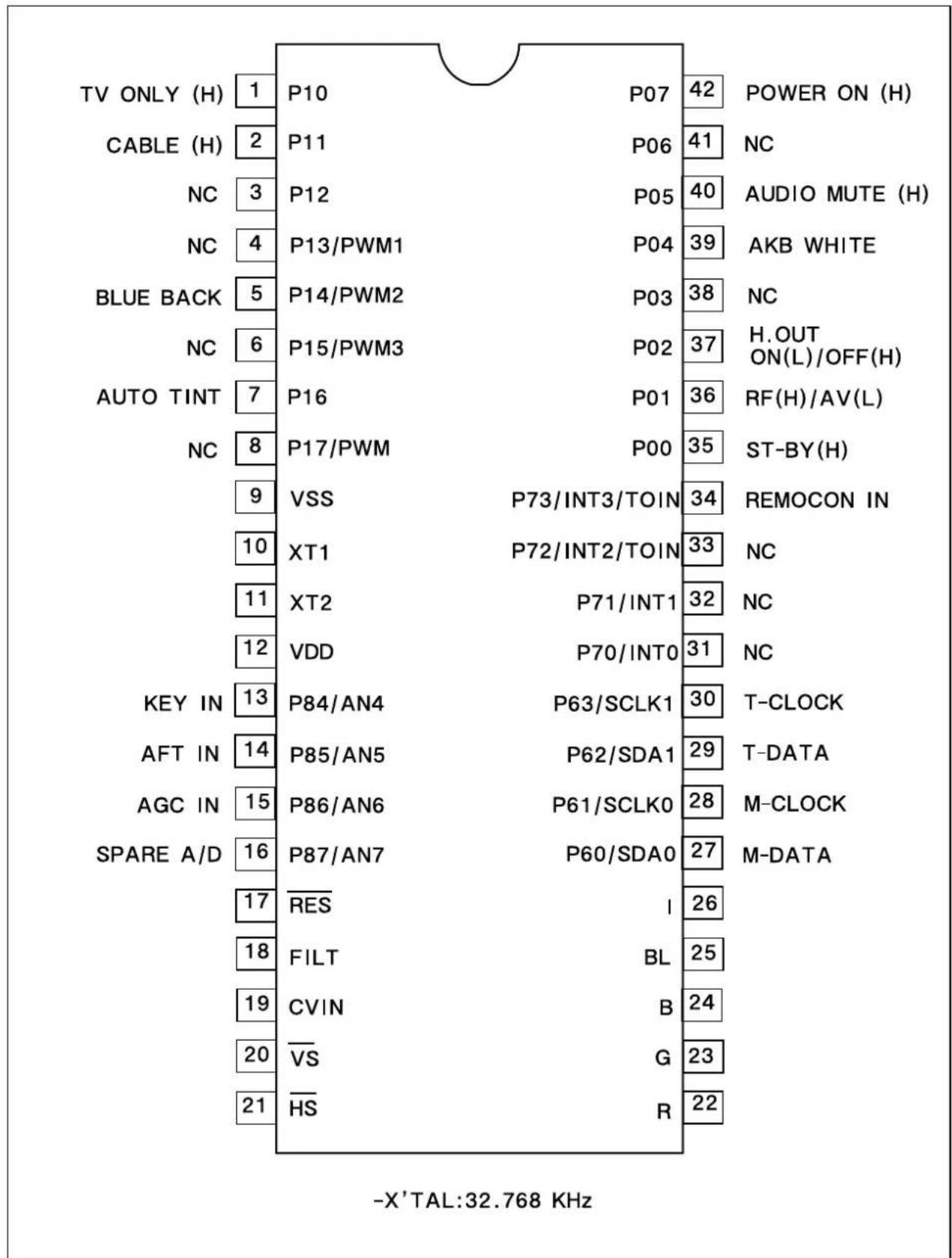
other
| Label | Value | | ------------- | ----- | | TV ONLY (H) | 1 | | CABLE (H) | 2 | | NC | 3 | | NC | 4 | | BLUE BACK | 5 | | NC | 6 | | AUTO TINT | 7 | | NC | 8 | | KEY IN | 13 | | AFT IN | 14 | | AGC IN | 15 | | SPARE A/D | 16 | | RES | 17 | | FILT | 18 | | CVIN | 19 | | VS | 20 | | HS | 21 | | P07 | 42 | | P06 | 41 | | P05 | 40 | | P04 | 39 | | P03 | 38 | | P02 | 37 | | P01 | 36 | | P00 | 35 | | P73/INT3/TOIN | 34 | | P72/INT2/TOIN | 33 | | P71/INT1 | 32 | | P70/INT0 | 31 | | P63/SCLK1 | 30 | | P62/SDA1 | 29 | | P61/SCLK0 | 28 | | P60/SDA0 | 27 | | I | 26 | | BL | 25 | | B | 24 | | G | 23 | | R | 22 | - X'TAL:32.768 KHzIC Description
1. Abstrack.
This specification is 1-Tuner Mono Model for North/South America, CCD 1-Chip MICOM LC863228A.
It is developing software specification for tuning only NTSC and 3 system TV F/S.
* 3 System : NTSC-M, PAL-M, PAL-N.
2. H/W Outline.
1) ROM : 28,672 x 8bits.tsc
: 15,872 x 8bits for CGROM.
2) RAM : 512 x 8bits
: 336 x 9bits. (for CRT Display)
3) OSD Function.
- Screen Display : 34 characters x 16 lines. (by software)
• RAM : 336 words. (9 bits per word)
Display area. : 34 words. x 8 lines.
1st control area. : 8 words. x 8 lines.
- Characters.
244 patterns programmable.
Up to 244 kinds of 16 x 17 dot characters.
Up to 244 kinds of 8 x 9 dot characters.
or
Up to 244 kinds of 16 x 32 dot characters used 16K bytes.
- Various characters attributes.
Character colors. : 16 colors
Character background colors. : 16 colors
Fringe / shadow colors. : 16 colors
Full screen colors. : 16 colors
Rounding.
Underline.
Italic character. (slanting)
- Attribute can be changed without spacing.
- Vertical display start line number can be set for each row independently. (Row can be overlapped.)
- Horizontal display start position can be set for each row independently.
- Different display modes can be set for each row independently.
Caption and Text mode / OSD mode 1/OSD mode 2(Quarter size) / Simplified graphic mode.
- Ten character sizes.
Horiz. x Vert. = (1x1), (1x2), (2x2), (2x4), (0.5x0.5)
(1.5x1), (1.5x2), (3x2), (3x4), (0.75x0.5)
- Shuttering and scrolling on each row.
3. System Feature.
1) The system for TV tuning is Frequency Synthesis type.
2) Closed Captions function is interior designed.
3) On Screen Displays function is interior designed.
4) Package.: 42 PIN SDIP.
5) Tuner (Pre-scaler.): I ^2 C Bus.
/PLL IC : TAU 6014-S (SIEMENS).
6) Remocon.: The IC of Transmission (MITSUBISHI M50560)
7) E ^2 PROM : 24C08(I ^2 C Bus) ◇ Apply one byte Read/Write mode.
8) 6-Local Key.: A/D Input Control. (Power, Ch Up/Down, Vol Up/Down, Menu)
9) Option S/W : Port Input Option Check.
10) IF/V/C/D IC : LA76814(, The only NTSC), LA76810(, 3-system)
4. Function.
1) C. C. D. function.
- A section of C. C. D. operates FCC based specification.
2) C. C. D. controlled function.
- Closed Caption Mode. (Off <--> C1 <--> C2 <--> T1 <--> T2 <--> Off)
- CC On Mute. (Off <--> C1 <--> C2 <--> Off)
- Closed Caption is prior to CC On Mute.
3) Tuning Function.
- I²C Bus.
- PLL IC Interface.
- FS 181 Channel (AIR 2-69CH, CABLE 1-125CH)
- AFT Operation (Fine Tuning) - 2.5Fn+2.5MHz
- AIR/CABLE (STD, HRC, IRC). Only Cable 5,6 CH is that AFT range is cover over broad-band. -2.5MHzFn + 3.5MHz..
- Memorize Channels. (If a channel is broadcasting, the channel is memorized.)
- Direct Tuning (09KEY)
- Channel Up/Down. (Memorized Channels) -> The Ch Up/Down buttons on the Remocon and on the front panel are same function.
- Search Channel Up/Down. (If No-Memory or only 1CH is Memory)
- Channel Memory. (ADD/DELETE)
- Channel Review Function.
- Last Channel Memory Function.
4) OSD Function.
- In Line (Video) Mode, Things (Items) that is concerned with Air and Cable disappear in the Menu.
- Channel, AV display.
- Small & Graphic ICON Menu.
- Volume / Picture control --> I ^2 C Bus Control
5) The Others Function.
- Video / Audio Mute Function.
- If a Channel is no signal, after 15 minutes is Auto-Power Off Function.
IC Description
- Auto Power On Function. (Power Restore function in the Special Menu)
- Heat Run Function. --- OSD White Back-Ground
- Sleep Timer.
- Wake Up Time Function.
- Off Time Function.
- Remote Reception & Control.
- Auto Tint.
- Power Restore.
- Input(TV/Line) Controlled function. ---- (Option)
- Reception.(Air/Cable : Factory Initial Condition) ---- (Option)
- Blue Background. ---- (Option)
- 3-Language ( North America : ENG/SPA/FRA, South America : ENG/SPA/POR ).
- E2PROM Interface (I2C Bus Control)
- CH 6 TRAP Function. (IS-31)
- PLL IC Band Data. (Control Byte 2 --> P3\~P0)
VHF L:1
VHF H : 2
CH6 TRAP : 5 (IS-31) AIR (Cable) CH 6 Only
UHF : 8
5. The Table of Option and Schedule.
| Model Name Pin Option | Application Reference | ||||
| CM-003 | #1 | Input | Video/TV | o | - Low (DC_0V) : Video. |
| - High (DC_5V) :TV. | |||||
| #2 | Reception | Air/Cable | o | - Low (DC_0V) : Air. | |
| - High (DC_5V) : Cable. | |||||
| #3 | Audio | Mono/Stereo | o | - Low (DC_0V) : Stereo. | |
| - High (DC_5V) : Mono. | |||||
| #5 | Bule Back | o | - Low (DC_0V) : Blue Back. | ||
| - High (DC_5V) : No Use | |||||
| #6 | XDS | X | - No Use. | ||
| #7 | Channel Lock | X | - No Use. | ||
| #4 | Brand OSD | DAEWOO / PHILCO | X | #4 #81 0 : DAEWOO0 1 : PH1LCO | |
| #8 | Display | ||||
| Tatal Sun | 7 | - Use. (No Use.) | |||
- Pin Description
| PIN Terminal Name | Explanation | Remarks | ||
| 1 | P10 | Input - High (DC_5V) : The only TV.(Option) - Low (DC_0V) : Line. (Video) | - Output Format.- CMOS/Nch- OD. | |
| 2 | P11 | Reception - High (DC_5V) : Cable.(Option) - Low (DC_0V) : Air. | ||
| 3 | P12 | Audio - High (DC_5V) : Mon.(Option) - Low (DC_0V) : Stereo. | ||
| 4 | P13/PWM1 | Remocon - High (DC_5V) : DAEWOO(Option) - Low (DC_0V) : NON | ||
| 5 | P14/PWM2 | Blue Back - High (DC_5V) : No Blue Back.(Option) - Low (DC_0V) : Blue Back. | ||
| 6 | P15/PWM3 | Option - High (DC_5V) : V-Chip.(V-Chip) - Low (DC_0V) : No V-Chip. | ||
| 7 | P16 | Option - High (DC_5V) : Auto Tint.(Auto Tint) - Low (DC_0V) : No Auto Tint. | ||
| 8 | P17/PWM | PWM | - High (DC_54) : PHILCO- LOW (DC_0V) : NON | |
| 9 | VSS | GNC | - GND- Negative power supply. | |
| 10 | XT1 | XT1 | - It uses 32.768KHz X-TAL.- 10 pin is input terminal for crystal oscillator.- 11 pin is output terminal for crystal oscillator. | |
| 11 | XT2 | XT2 | ||
| 12 | VDD | VDD | - +5V ( ± 0.5V )- Positive power supply. | |
| 13 | P84 / AN4 | KEY IN | - Power, Ch up/down, Vol up/down, Menu. | |
| 14 | P85 / AN5 | AFT IN | - DC value that comes from the 10 pin of LA76810/14 | |
| 15 | P86 / AN6 | AGC IN | - Connect this port to AGC of Tuner- Default Voltage : 3.75V- Variable Voltages : 3.25V, 3.5V, 4.0V | |
IC Description
| PIN Terminal Name | Explanation | Remarks | ||
| 16 | P87 / AN7 | SPARE A/D - | 16 pin is a spare pin.- 13 pin to 16 pin- 4 bit input / output port, Nch-OD output.- Input or output can be specified for each bit.- Other function.AD converter input port ( 4 lines). | |
| 17 | /RES | /RES | - Reset terminal.- Active Low. | |
| 18 | FILT | Filter | - Filter terminal for PLL.- Output terminal. | |
| 19 | CVIN | CVSB IN | - Video signal input terminal. | |
| /VS20 | /VS | - Vertical synchronization signal input terminal. | ||
| 21 | /HS | /HS | - Horizontal synchronization signal input terminal. | |
| 22 | R | R | - Red output terminal of RGB image. | |
| 23 | G | G | - Green output terminal of RGB image. | |
| 24 | B | B | - Blue output terminal of RGB image. | |
| 25 | BL | BL | - Fast blanking control signal.- Switch TV image signal and caption / OSD image signal.- Output terminal. | |
| 26 | I | I | - Intensity output terminal of RGB image signal.- Output terminal. | |
| 27 | P60/SDA 0 | ROM DataMain IC Data | - 6-bit input / output port.- Input / output can be specified for each bit.- Other function. | |
| 28 | P61/SCLK 0 | ROM CLKMain IC CLK | P60 IIC0 data I/O | |
| P61 IIC0 clock output. | ||||
| 29 | P62/SDA 1 Tuner Data | P62 IIC1 data I/O. | ||
| P63 IIC1 clock output. | ||||
| 30 | P63/SCLK 1 | Tuner CLK | ||
| 31 | P70 / INT 0 | Sound Input | -4-bit input / output port.-Input or output can be specified for each bit.-#31: Only Cn-220, ITT(MSP)Low: Front Mask / Mono, High: Back / Stereo.-Other function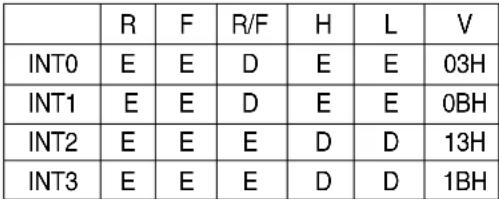 -Interrupt receiver format, vector addresses. -Interrupt receiver format, vector addresses. | |
| 32 | P71 / INT 1 | N.C | ||
| 33 | P72 / INT 2/TO IN | SD In | ||
| 34 | P72 / INT 3 /TO IN | Remocon In | P70INT0input/HOLDrelease input / Nch-Tr. output for watchdog timer. | |
| P71INT1 input/HOLD release input. | ||||
| P72INT2 input/Timer 0 event input. | ||||
| P73INT3 input (noise rejection filter attached) / Timer | ||||
| ♣Notice R:Rising, F:falling, H:H level,L: L level, V: Vector, E:Enable, D:Disale. | ||||
| 35 | P00 | ST_By LED | -Use only Japan Model.-This port use when is Stand-By status.-Condition: Input AC Power On.-Power off: 'High(DC 5V)' Output.(Red)-Power on: 'Low(DC 0V)' Output. | |
| 36 P01 TV / VIDEO - TV Mode: 'High' Line (Video) Mode: 'Low'. | ||||
| 37 P02 H.Out - Use to discharge High Voltage when TV set turns off. | ||||
| 38 P03 Sound Reset - Sound IC Reset: ITT. | -Only Cn-220 | |||
| 39 P04 AKB - Use when control AKB (High Beam: 'High(5V)' Output) | ||||
| 40 | P05 | Audio Mute | -Use only 'read data' of 'LA76814/10. | |
| 41 P06 Video White | -Use when TV set turns off. | |||
| 42 | P07 | Power | -Use when does power off/on.-.Power Off: Output 'Low(DC 0V).'Power On: Output 'High(DC 5V)' | |
Output form and existence of pull-up resistor for every port can be specified for each bit
At port 1, "Programmable pull-up resistor provided" when specifying either CMOS or N-ch open drain output.
Port status in reset.
| Terminal | I/O | Pull-up resistor status at selecting pull-up option. |
| Port 0 | I | Pull-up resistor OFF, ON after reset release. |
| Port 1 | I | Programmable pull-up resistor OFF. |
IC Description
I101
LA76805 : IC VIDEO PROCESSOR
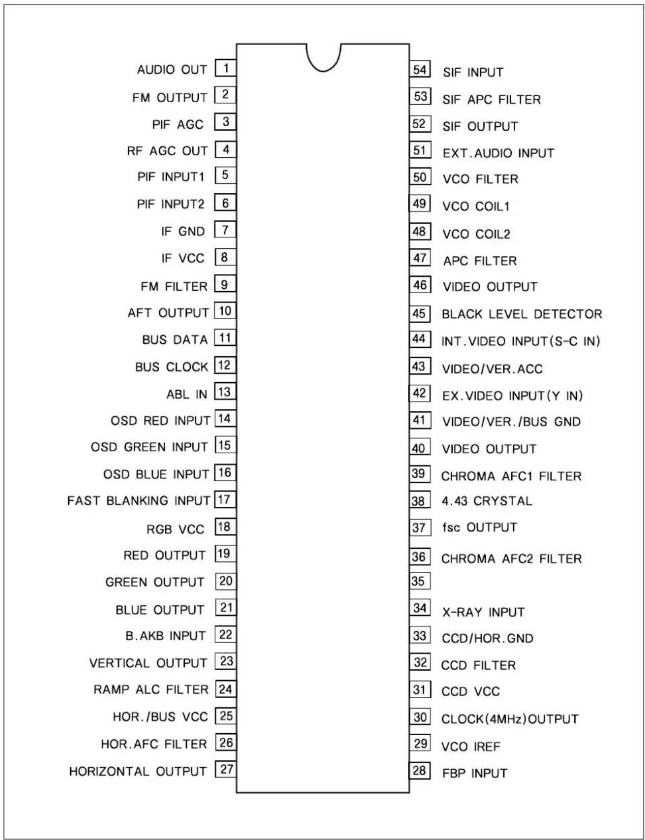
other
| Label | Value | |---|---| | AUDIO OUT | 1 | | FM OUTPUT | 2 | | PIF AGC | 3 | | RF AGC OUT | 4 | | PIF INPUT1 | 5 | | PIF INPUT2 | 6 | | IF GND | 7 | | IF VCC | 8 | | FM FILTER | 9 | | AFT OUTPUT | 10 | | BUS DATA | 11 | | BUS CLOCK | 12 | | ABL IN | 13 | | OSD RED INPUT | 14 | | OSD GREEN INPUT | 15 | | OSD BLUE INPUT | 16 | | FAST BLANKING INPUT | 17 | | RGB VCC | 18 | | RED OUTPUT | 19 | | GREEN OUTPUT | 20 | | BLUE OUTPUT | 21 | | B.AKB INPUT | 22 | | VERTICAL OUTPUT | 23 | | RAMP ALC FILTER | 24 | | HOR./BUS VCC | 25 | | HOR.AFC FILTER | 26 | | HORIZONTAL OUTPUT | 27 | 54 SIF INPUT 53 SIF APC FILTER 52 SIF OUTPUT 51 EXT.AUDIO INPUT 50 VCO FILTER 49 VCO COIL1 48 VCO COIL2 47 APC FILTER 46 VIDEO OUTPUT 45 BLACK LEVEL DETECTOR 44 INT.VIDEO INPUT(S-C IN) 43 VIDEO/VER.ACC 42 EX.VIDEO INPUT(Y IN) 41 VIDEO/VER./BUS GND 40 VIDEO OUTPUT 39 CHROMA AFC1 FILTER 38 4.43 CRYSTAL 37 fsc OUTPUT 36 CHROMA AFC2 FILTER 35 X-RAY INPUT 34 CCD/HOR.GND 33 CCD FILTER 32 CCD VCC 31 CCD VCC 30 CLOCK(4MHz)OUTPUT 29 VCO IREF 28 FBP INPUTTroubleshooting Guide
- NO POWER
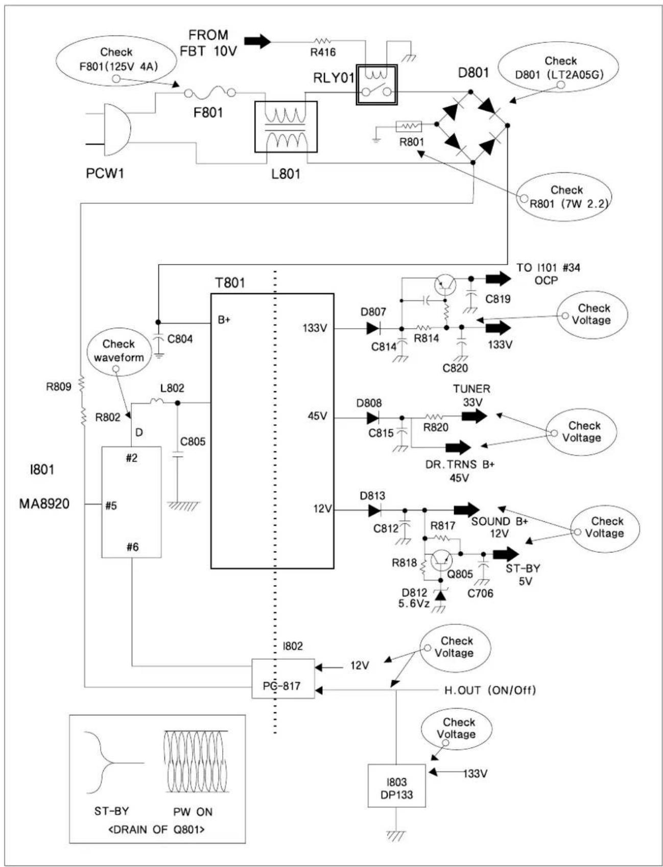
text_image
FROM FBT 10V R416 F801 RLY01 D801 Check F801(125V 4A) F801 L801 R801 D801 LT2A05G PCW1 Check R801 (7W 2.2) T801 B+ 133V TO I101 #34 OCP C819 Check waveform C804 C814 R814 133V C820 I801 MA8920 D807 C814 R814 TUNER 33V Check Voltage R802 L802 D C805 45V C815 R820 Check Voltage D808 DR.TRNS B+ 45V D813 C812 R817 SOUND B+ 12V Check Voltage R818 Q805 ST-BY 5V D812 5.6Vz C706 PG-817 H.OUT (ON/Off) I802 12V Check Voltage I803 DP133 ST-BY PW ONTroubleshooting Guide
2. NO PICTURE
| Check the waveform of I101 #46 | NG : Go to the figure © |
| OK : Go the figure ⓓ |
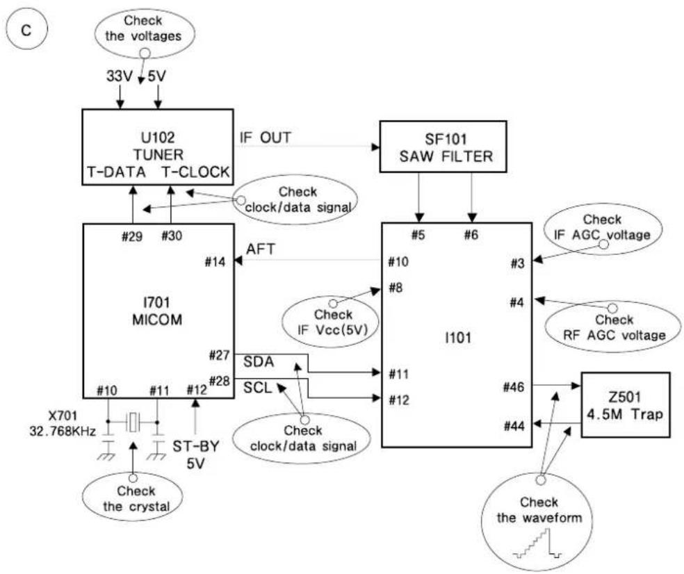
flowchart
graph TD
    A["Check the voltages"] --> B["33V 5V"]
    B --> C["U102 TUNER T-DATA T-CLOCK"]
    C --> D["IF OUT"]
    D --> E["SF101 SAW FILTER"]
    E --> F["I101"]
    F --> G["Z501 4.5M Trap"]
    G --> H["Check the waveform"]
    F --> I["SDA"]
    F --> J["SCL"]
    F --> K["Check clock/data signal"]
    F --> L["Check IF Vcc(5V)"]
    F --> M["Check clock/data signal"]
    F --> N["Check IF AGC voltage"]
    F --> O["Check RF AGC voltage"]
    F --> P["X701 32.768KHz"]
    F --> Q["#10 #11 #12 #27 #28"]
    F --> R["#10 #8 #4"]
    F --> S["#11 #12 #46 #44"]
    F --> T["X701 32.768KHz ST-BY 5V"]
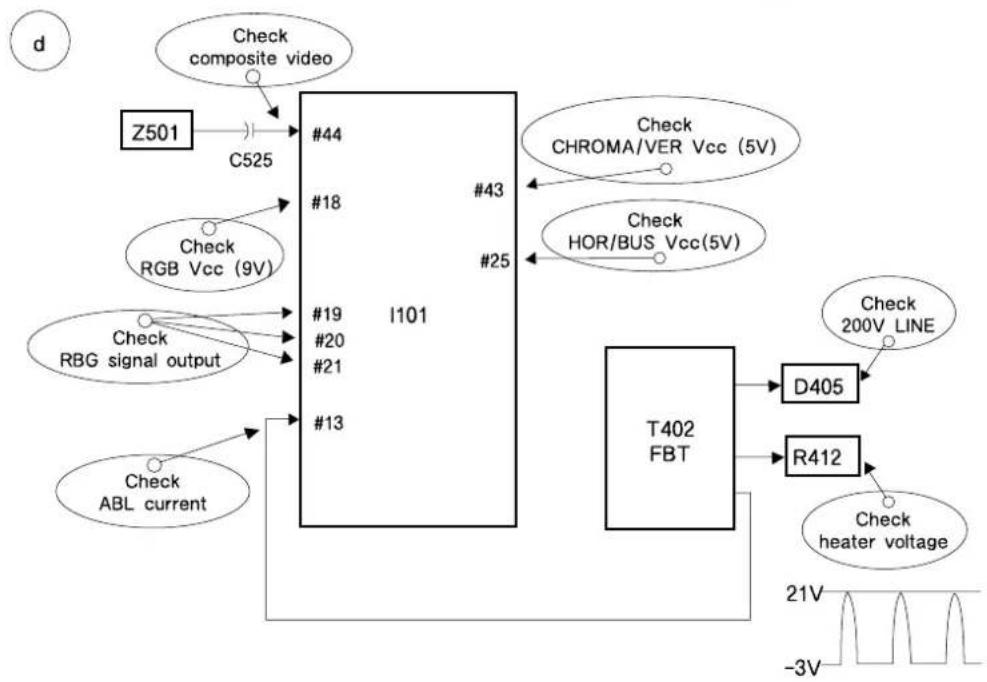
flowchart
graph TD
    A["Z501"] --> B["C525"]
    B --> C["#44"]
    C --> D["#18"]
    D --> E["I101"]
    E --> F["#13"]
    F --> G["T402 FBT"]
    G --> H["D405"]
    G --> I["R412"]
    H --> J["Check 200V LINE"]
    I --> K["Check heater voltage"]
    L["Check composite video"] --> B
    M["Check RGB Vcc (9V)"] --> D
    N["Check RBG signal output"] --> E
    O["Check ABL current"] --> F
    P["Check CHROMA/VER Vcc (5V)"] --> E
    Q["Check HOR/BUS Vcc(5V)"] --> E
Troubleshooting Guide
3. NO SOUND
| Check audio output signal of I101 #1 | NG : Go to the figure ⓔ |
| OK : Go the figure ⓕ |
e
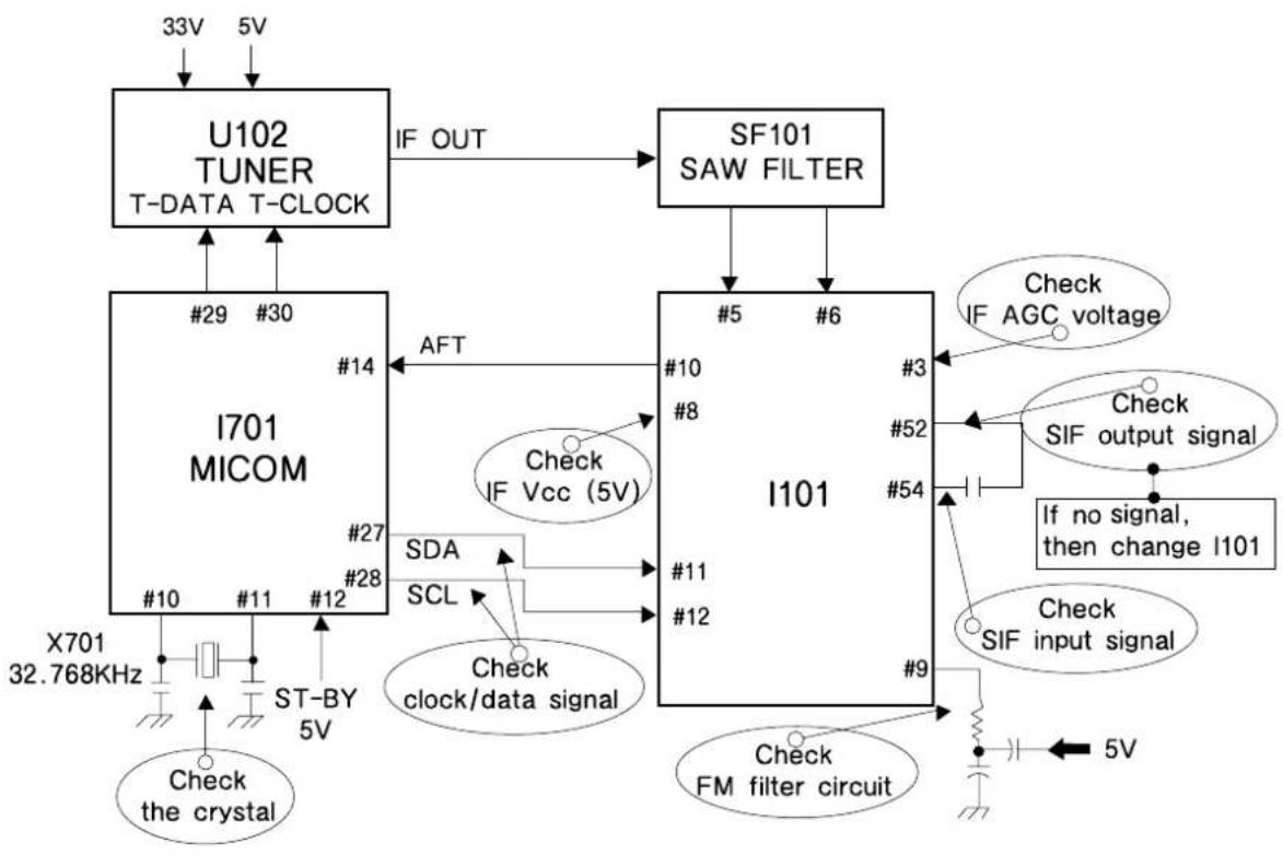
flowchart
graph TD
    A["U102 TUNER T-DATA T-CLOCK"] -->|IF OUT| B["SF101 SAW FILTER"]
    C["I701 MICOM"] -->|AFT| D["I101"]
    D -->|Check IF Vcc (5V)| E["I701 MICOM"]
    D -->|Check IF AGC voltage| F["I101"]
    D -->|Check SIF output signal| G["I101"]
    D -->|Check SIF input signal| H["I101"]
    D -->|Check FM filter circuit| I["I101"]
    D -->|Check clock/data signal| J["I701 MICOM"]
    D -->|Check the crystal| K["X701 32.768KHz"]
    D -->|Check clock/data signal| L["SCL"]
    D -->|Check clock/data signal| M["SDA"]
    D -->|Check clock/data signal| N["AFT"]
    D -->|Check clock/data signal| O["ST-BY 5V"]
    D -->|Check clock/data signal| P["X701 32.768KHz"]
f
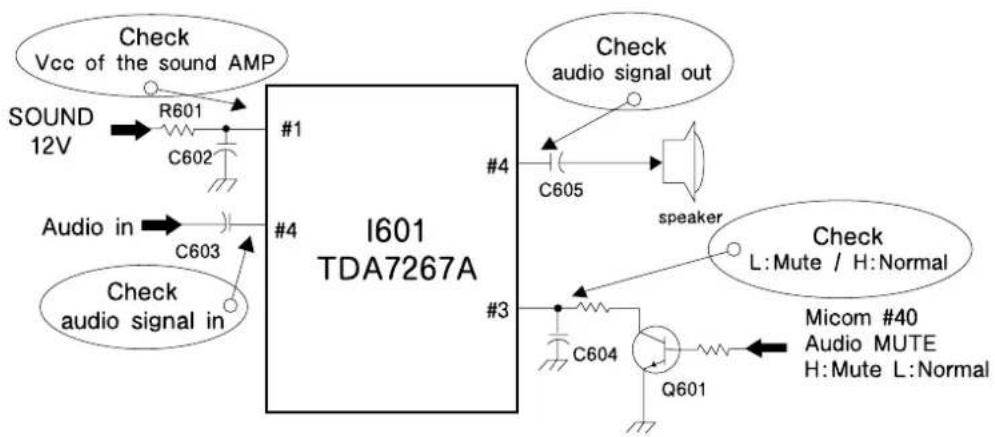
text_image
Check Vcc of the sound AMP SOUND 12V R601 C602 #1 Audio in C603 #4 Check audio signal in I601 TDA7267A #4 #3 #4 Check audio signal out C605 speaker Check L:Mute / H:Normal Micom #40 Audio MUTE H:Mute L:Normal C604 Q601Troubleshooting Guide
4. CH DON'T STOP
| Check the input signal conditions | NG : Loss of signal or weak signal |
| OK : Go to the figure ⑨ |

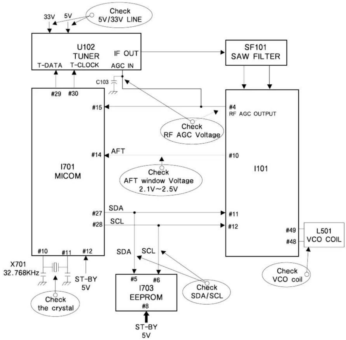
flowchart
graph TD
    A["I701 MICOM"] -->|Check the crystal 32.768KHz| B["X701"]
    A -->|ST-BY 5V| C["I703 EEPROM #8"]
    A -->|ST-BY 5V| D["I101"]
    A -->|AFT window Voltage 2.1V~2.5V| E["SFAI TUNER IF OUT AGC IN"]
    A -->|Check RF AGC Voltage| F["SF101 SAW FILTER"]
    A -->|Check VCO coil| G["L501 VCO COIL"]
    A -->|Check 5V/33V LINE| H["Check 5V"]
    A -->|Check 5V/33V LINE| I["Check 5V"]
    A --> J["T-DATA T-CLOCK"]
    A --> K["T-DATA T-CLOCK"]
    A --> L["T-DATA T-CLOCK"]
    A --> M["T-DATA T-CLOCK"]
    A --> N["T-DATA T-CLOCK"]
    A --> O["T-DATA T-CLOCK"]
    A --> P["T-DATA T-CLOCK"]
    A --> Q["T-DATA T-CLOCK"]
    A --> R["T-DATA T-CLOCK"]
    A --> S["T-DATA T-CLOCK"]
    A --> T["T-DATA T-CLOCK"]
    A --> U["T-DATA T-CLOCK"]
    A --> V["T-DATA T-CLOCK"]
    A --> W["T-DATA T-CLOCK"]
    A --> X["T-DATA T-CLOCK"]
    A --> Y["T-DATA T-CLOCK"]
    A --> Z["T-DATA T-CLOCK"]
    A --> AA["T-DATA T-CLOCK"]
    A --> AB["T-DATA T-CLOCK"]
    A --> AC["T-DATA T-CLOCK"]
    A --> AD["T-DATA T-CLOCK"]
    A --> AE["T-DATA T-CLOCK"]
    A --> AF["T-DATA T-CLOCK"]
    A --> AG["T-DATA T-CLOCK"]
    A --> AH["T-DATA T-CLOCK"]
    A --> AI["T-DATA T-CLOCK"]
    A --> AJ["T-DATA T-CLOCK"]
    A --> AK["T-DATA T-CLOCK"]
    A --> AL["T-DATA T-CLOCK"]
    A --> AM["T-DATA T-CLOCK"]
    A --> AN["T-DATA T-CLOCK"]
    A --> AO["T-DATA T-CLOCK"]
    A --> AP["T-DATA T-CLOCK"]
    A --> AQ["T-DATA T-CLOCK"]
    A --> AR["T-DATA T-CLOCK"]
    A --> AS["T-DATA T-CLOCK"]
    A --> AT["T-DATA T-CLOCK"]
    A --> AU["T-DATA T-CLOCK"]
    A --> AV["T-DATA T-CLOCK"]
    A --> AW["T-DATA T-CLOCK"]
    A --> AX["T-DATA T-CLOCK"]
    A --> AY["T-DATA T-CLOCK"]
    A --> AZ["T-DATA T-CLOCK"]
    A --> BA["T-DATA T-CLOCK"]
    A --> BB["T-DATA T-CLOCK"]
    A --> BC["T-DATA T-CLOCK"]
    A --> BD["T-DATA T-CLOCK"]
    A --> BE["T-DATA T-CLOCK"]
    A --> BF["T-DATA T-CLOCK"]
    A --> BG["T-DATA T-CLOCK"]
    A --> BH["T-DATA T-CLOCK"]
    A --> BI["T-DATA T-CLOCK"]
    A --> BJ["T-DATA T-CLOCK"]
    A --> BK["T-DATA T-CLOCK"]
    A --> BL["T-DATA T-CLOCK"]
    A --> BM["T-DATA T-CLOCK"]
    A --> BN["T-DATA T-CLOCK"]
    A --> BO["T-DATA T-CLOCK"]
    A --> BP["T-DATA T-CLOCK"]
    A --> BQ["T-DATA T-CLOCK"]
    A --> BR["T-DATA T-CLOCK"]
    A --> BS["T-DATA T-CLOCK"]
    A --> BT["T-DATA T-CLOCK"]
    A --> BU["T-DATA T-CLOCK"]
    A --> BV["T-DATA T-CLOCK"]
    A --> BW["T-DATA T-CLOCK"]
5. NO COLOR
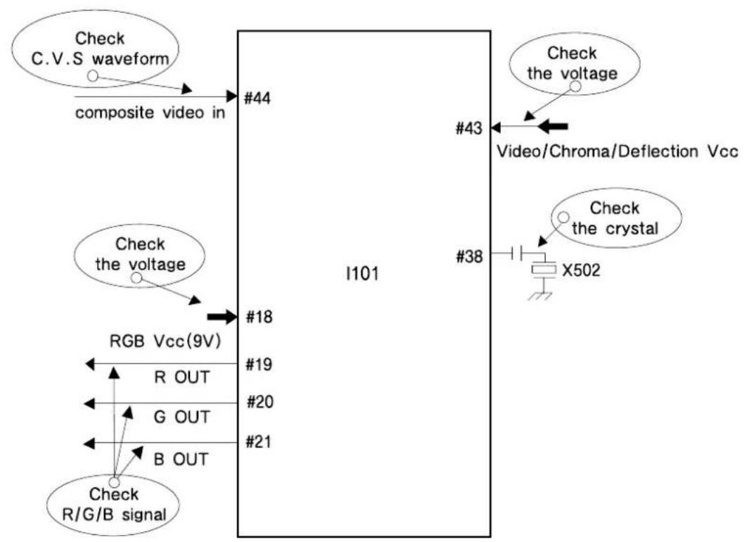
flowchart
graph TD
    A["Check C.V.S waveform"] --> B["composite video in"]
    B --> C["#44"]
    D["Check the voltage"] --> E["#18"]
    F["RGB Vcc(9V)"] --> G["R OUT"]
    G --> H["G OUT"]
    H --> I["B OUT"]
    I --> J["Check R/G/B signal"]
    K["I101"] --> L["#19"]
    L --> M["#20"]
    M --> N["#21"]
    O["#38"] --> P["X502"]
    Q["#43"] --> R["Video/Chroma/Deflection Vcc"]
    S["Check the voltage"] --> T["Video/Chroma/Deflection Vcc"]
    U["Check the crystal"] --> V["X502"]
6. NO VERTICAL DEFLECTION
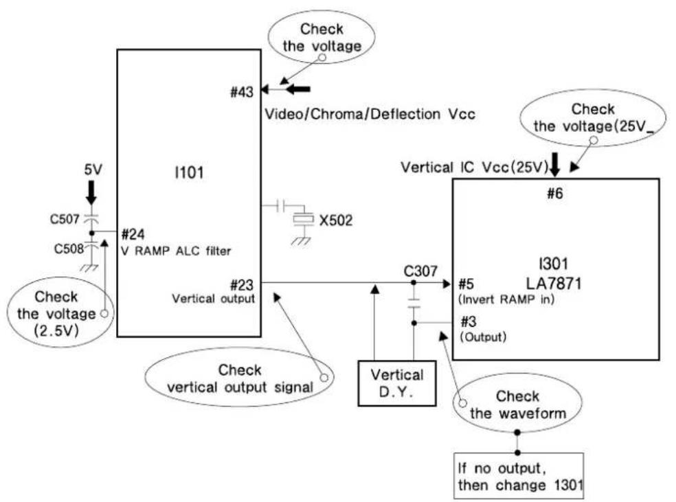
flowchart
graph TD
    A["I101"] -->|Check the voltage (2.5V)| B["C507"]
    A -->|Check the voltage (25V)| C["X502"]
    A -->|Check vertical output signal| D["Vertical D.Y."]
    A -->|Check the voltage (24 V RAMP ALC filter)| E["X508"]
    A -->|Check the voltage (25V) Video/Chroma/Deflection Vcc| F["X502"]
    A -->|Check vertical output signal| G["Vertical output"]
    A -->|Check the voltage (25V)| H["X502"]
    A -->|Check the voltage (25V) Video/Chroma/Deflection Vcc| I["X502"]
    A -->|Check the voltage (25V) Vertical IC Vcc(25V)| J["X502"]
    A -->|Check the voltage (25V) Vertical IC Vcc(25V) #6| K["X502"]
    A -->|Check the voltage (25V) Vertical IC Vcc(25V) #3 (Output) #5 (Invert RAMP in)]
    A -->|Check the waveform If no output, then change 1301| L["X502"]
    A -->|Check the waveform #3 (Output) #5 (Invert RAMP in)]
    A -->|Check the waveform #3 (Output) #6 (Invert RAMP in)]
Troubleshooting Guide
7. NO ON-SCREEN DISPLAY
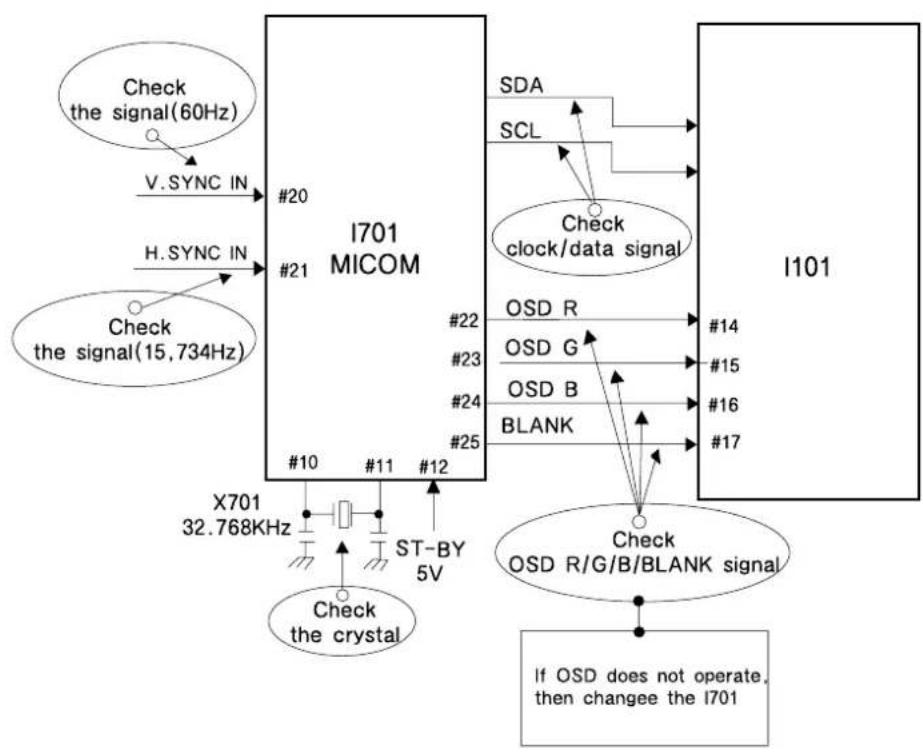
flowchart
graph TD
    A["Check the signal(60Hz)"] -->|V.SYNC IN| B["I701 MICOM"]
    C["Check the signal(15,734Hz)"] -->|H.SYNC IN| B
    B --> D["#20"]
    B --> E["#21"]
    B --> F["#10"]
    B --> G["#11"]
    B --> H["#12"]
    B --> I["X701 32.768KHz"]
    I --> J["Check the crystal"]
    B --> K["SDA"]
    B --> L["SCL"]
    B --> M["Check clock/data signal"]
    M --> N["OSD R"]
    M --> O["OSD G"]
    M --> P["OSD B"]
    M --> Q["BLANK"]
    B --> R["#22"]
    B --> S["#23"]
    B --> T["#24"]
    B --> U["#25"]
    B --> V["#14"]
    B --> W["#15"]
    B --> X["#16"]
    B --> Y["#17"]
    B --> Z["Check OSD R/G/B/BLANK signal"]
    Z --> AA["If OSD does not operate, then changee the I701"]
8. REMOTE CONTROL DOES NOT OPERATE
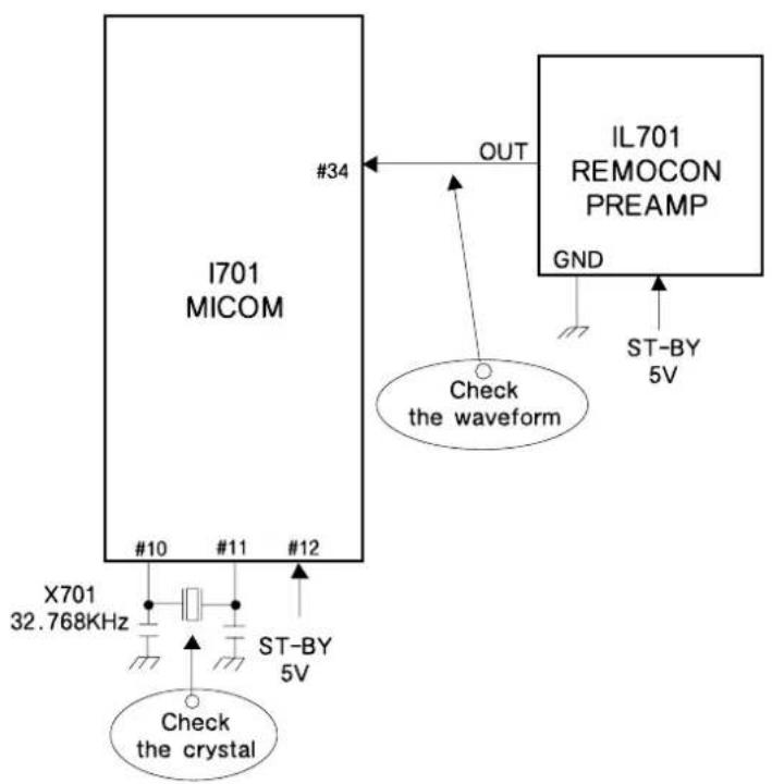
text_image
I701 MICOM #34 OUT IL701 REMOCON PREAMP GND ST-BY 5V Check the waveform X701 32.768KHz #10 #11 #12 ST-BY 5V Check the crystalDAEWOO
ELECTRONICS