TW-HD-MOUNT502 - Accessory Ventev - Free user manual and instructions
Find the device manual for free TW-HD-MOUNT502 Ventev in PDF.

| Product Type | Universal Mounting Accessory |
| Compatible Devices | Smartphones, Tablets, GPS Devices |
| Dimensions | 5.0 x 3.5 x 2.0 inches (127 x 89 x 51 mm) |
| Weight | 0.35 lbs (160 g) |
| Material | High-grade ABS Plastic and Silicone |
| Mounting Type | Suction Cup and Adhesive Pad |
| Rotation | 360° Swivel and 180° Tilt |
| Max Device Width | 4.0 inches (102 mm) |
| Max Device Weight | 1.5 lbs (680 g) |
| Power Supply | None (Passive) |
| Main Functions | Secure device holding, hands-free operation, versatile positioning |
| Installation | Tool-free, easy stick-on or suction mount |
| Cleaning | Wipe with a soft, dry cloth; mild soap if needed |
| Maintenance | Check suction cup seal periodically; clean mounting surfaces |
| Safety | Keep out of reach of children; do not over-tighten |
| Spare Parts | Replacement suction cups available separately |
| Repairability | Non-repairable; replace if damaged |
| General Information | Designed for in-car or desk use; complies with RoHS |
Frequently Asked Questions - TW-HD-MOUNT502 Ventev
User questions about TW-HD-MOUNT502 Ventev
0 question about this device. Answer the ones you know or ask your own.
Ask a new question about this device
Download the instructions for your Accessory in PDF format for free! Find your manual TW-HD-MOUNT502 - Ventev and take your electronic device back in hand. On this page are published all the documents necessary for the use of your device. TW-HD-MOUNT502 by Ventev.
USER MANUAL TW-HD-MOUNT502 Ventev
Co-Location Mount for Cisco Access Points
The Co-Locating Mount can be mounted on any flat surface including, but not limited to, walls, ceilings, and I-beams. Mounting hardware is not included with this product. User should identify the mounting surface and then purchase the appropriate mounting hardware. Recommended hardware by mounting surface:
Dry Wall Mounting:
4x Wall Anchors
4x Dry Wall Screws that will fit inside the holes shown on Figure 2.
Wood Wall Mounting:
4x Wood Screws that will fit inside the holes shown on Figure 2.
4x Locking Washers
Metal Surface Mounting
4x Metal Screws that will fit inside the holes shown on Figure 2.
4x Flat Washers
4x Locking Washers
CAUTION! Before installing, ensure the surface on which the Mount will be installed can support the fully assembled unit's weight which includes the mount itself, the access point, and the antenna.
Co- Location Mount Installation Instructions
text_image
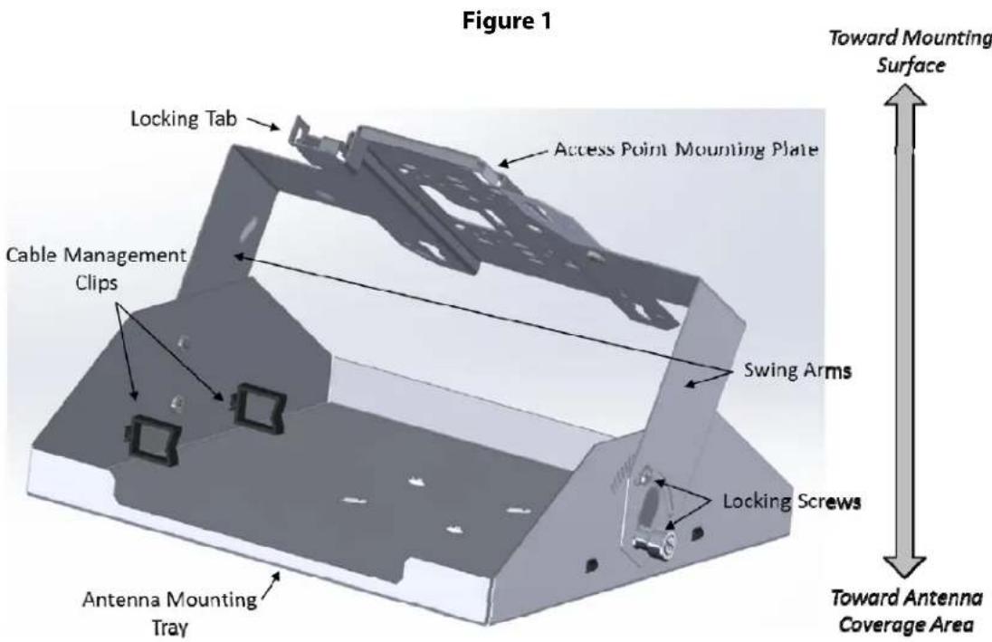
Figure 1 Toward Mounting Surface Locking Tab Access Point Mounting Plate Cable Management Clips Swing Arms Locking Screws Antenna Mounting Tray Toward Antenna Coverage Area- Identify the major parts of the Co-Locating Mount in Figure 1. Refer to it as needed for the remaining steps.
Co-Location Mount for Cisco Access Points
Installation Instructions (continued)
Figure 2
text_image
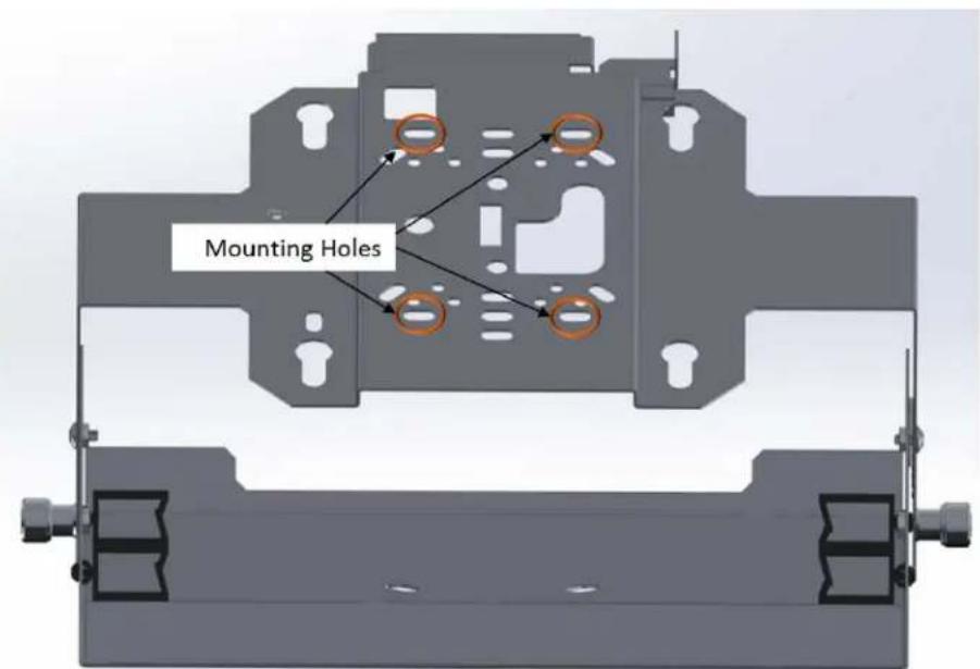
Mounting Holes- In Figure 2, locate the four circled Access Point Mounting Holes on the Access Point Mounting Plate.
- Place the Access Point Mounting Plate flat against the mounting surface. Mark the location of the four Mounting Holes on the mounting surface.
- Remove the Access Point Mounting Plate from the mounting surface.
- Drill holes at the four marked locations.
- Optional Step for Dry Wall Mounting: Insert the four wall anchors into the four drilled holes until the anchors are flush with the wall surface.
- Place the Access Point Mounting Plate flat against the mounting surface so that the four drilled holes are visible through the four Mounting Holes.
- Put washers around screws or bolts, as appropriate.
- Insert a bolt or screw through the first Mounting Hole and screw into place until the screw is tight. Repeat for the three remaining Mounting Holes. The Co-Locating Mount is now secured to the mounting surface.
Co-Location Mount for Cisco Access Points
Installation Instructions (continued)
Figure 3
text_image
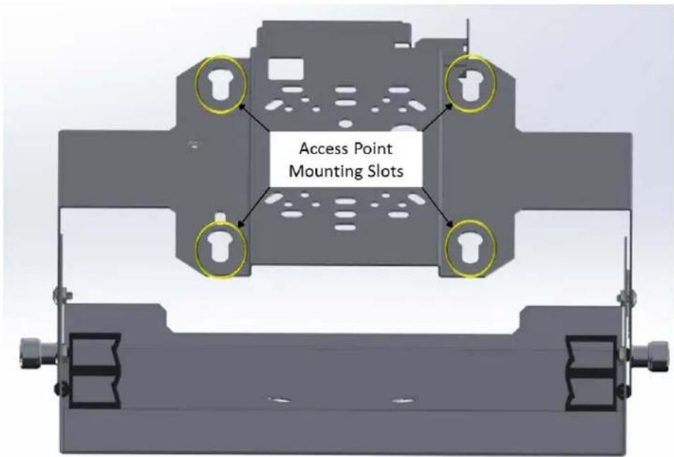
Access Point Mounting Slots-
Refer to Figure 3. Insert the access point's rubber mounting feet into the Mount's Access Point Mounting Slots.
-
Slide the mounting feet inside the Mounting Slots until a "snap" is heard. The access point is now securely mounted to the Access Point Mounting Plate.
Co-Location Mount for Cisco Access Points
Installation Instructions (continued)
Figure 4

text_image
Antenna Mounting Tray Antenna Mounting Holes- Refer to Figure 4. Remove the nuts and washers from antenna mounting bolts located at rear of the antenna. Push the antenna's mounting bolts through the Antenna Mounting Holes in the Antenna Mounting Tray.
- Re-attach antenna washers and nuts and tighten them to hold antenna securely against Mounting Tray.
- Run antenna cables through cable management clips and attach cable connectors to Access Point.
- Optional step for positioning antenna: Loosen the Antenna Mounting Tray's thumb screws and locking screws. Rotate the Antenna Mounting Tray to achieve the desired antenna position. Tighten all screws.
- Optional step for securing the access point: The access point can be secured to the Access Point Mounting Plate through the locking tab. The most common method is to thread a zip-tie through the Mounting Plate's locking tab and the access point's adjacent locking tab and tighten the zip-tie.