TW-CTEN-P - Uncategorized Ventev - Free user manual and instructions
Find the device manual for free TW-CTEN-P Ventev in PDF.

Pick your language and provide your email: we'll send you a specifically translated version.
User questions about TW-CTEN-P Ventev
0 question about this device. Answer the ones you know or ask your own.
Ask a new question about this device
No questions yet. Be the first to ask one.
Download the instructions for your Uncategorized in PDF format for free! Find your manual TW-CTEN-P - Ventev and take your electronic device back in hand. On this page are published all the documents necessary for the use of your device. TW-CTEN-P by Ventev.
USER MANUAL TW-CTEN-P Ventev
12"x24"x7" Universal Ceiling Tile Enclosure Installation Instructions
- Prepare the ceiling tile grid for a 1' × 2' or 2' × 2' installation.
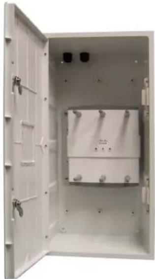
- Determine the correct mounting height of the access point (AP) mounting plate. Use the included standoffs for APs with integrated antennas (Figure 1). For AP installations using rubber duck antennas, do not use the mounting plate standoffs (Figure 2).
- Secure the AP mounting plate on the enclosure mounting plate (Figure 3) with the appropriate hardware. For most Cisco APs, the mounting holes are already pre-drilled into the mounting plate. For all other APs, use self-tapping screws.
- Install the desired door insert.
- Place the enclosure into the ceiling tile grid. Pull power and Ethernet connections through the provided cord grips as needed.
- If desired, install the included ceiling tile insert for a 2' x 2' installation.
- Secure the enclosure to the ceiling structure if required by local building codes.
- Connect the power and Ethernet to the AP as recommended by the AP manufacturer.
- Install the AP onto the mounting plate.
- Close the enclosure door and turn the locking mechanism to lock the enclosure door (Figure 4).

natural_image
Interior view of an open electrical enclosure with a central display unit (no text or symbols visible)
natural_image
Interior view of an open electrical enclosure showing a central switch and mounting bracket (no text or symbols visible)Figure 1
natural_image
Open white electrical cabinet with internal components and mounting holes (no visible text or symbols)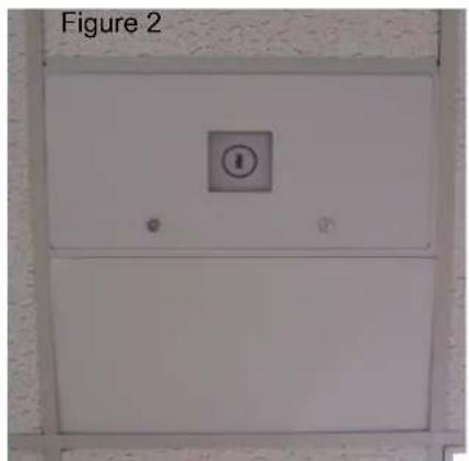
text_image
Figure 2Figure 4

natural_image
Interior view of an open white industrial control cabinet with internal compartments and mounting fixtures (no visible text or symbols)Figure 3
12"x24"x7" Universal Ceiling Tile Enclosure Installation Instructions
- The ceiling tile enclosure has four holes in the back for easy mounting (Figure 1).
- There are two eyebolts provided along with nuts, washers and lock washers to secure the enclosure to your ceiling structure based on your local building codes (Figure 2).
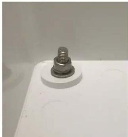
- Secure a nut, lock washer and washer to the top of the eye bolt (Figure 3) Insert into the hole of your choice on the back of the enclosure.
- Inside the enclosure, secure the bottom of the eye bolt with a washer, lock washer and nut (Figure 4).
- Repeat the first four steps for the second eye bolt to be placed in the hole of your choice at the back of the enclosure.
- Once eye bolts are installed, secure the enclosure to the ceiling with wire or cable through the eye bolts to the ceiling structure per local building codes.

natural_image
Exterior view of a rectangular metal enclosure with mounting holes (no text or symbols visible)Figure 1

natural_image
Close-up of a metal anchor bolt with multiple bolts and nuts arranged on a plain background (no text or symbols visible)Figure 2

natural_image
Metallic hook-shaped object with a small bolt and nut (no text or symbols visible)Figure 3
natural_image
Close-up of a metallic bolt head mounted on a white base plate (no text or symbols visible)Figure 4