TW-HWM-C-CVR - Uncategorized Ventev - Free user manual and instructions
Find the device manual for free TW-HWM-C-CVR Ventev in PDF.


User questions about TW-HWM-C-CVR Ventev
0 question about this device. Answer the ones you know or ask your own.
Ask a new question about this device
Download the instructions for your Uncategorized in PDF format for free! Find your manual TW-HWM-C-CVR - Ventev and take your electronic device back in hand. On this page are published all the documents necessary for the use of your device. TW-HWM-C-CVR by Ventev.
USER MANUAL TW-HWM-C-CVR Ventev
Assembly Instructions Compact Wall Mount
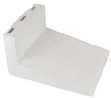
The new TerraWave Compact Horizontal Wall Mount with Universal T-Bar Mounting Plate is designed to provide optimal Wi-Fi coverage indoors. The mount can comfortably fit most indoor Access Points and provides maximum protection from dust and tampering without RF interference. Mounts to any wall surface, making it ideal for warehouses, hospitals, campuses and universities. Designed using powder-coated aluminum, this lightweight mount is easy to deploy and ensures safe and reliable installation.
natural_image
White plastic mechanical bracket with a flat top and side cutouts (no text or symbols)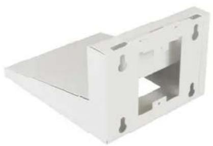
natural_image
White plastic mechanical component with a central square cutout and four mounting holes (no text or symbols visible)Assembly Components
◇ Qty 1 wall mount with lid assembled
◇ Qty 4 Screws #8-32
◇ Qty 1 Cotter Pin
Assembly Instructions
Step 1 - Open the lid of the enclosure by pulling the lid Forward and lifting up to release the locking tabs on the lid
Step 2 – Depending on the AP and bracket being used follow the correct figure:
natural_image
Technical line drawing of a mechanical device with internal components and mounting holes (no text or symbols)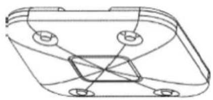
natural_image
Technical line drawing of a mechanical component with mounting holes and internal brackets (no text or symbols)Assembly Instructions Compact Wall Mount
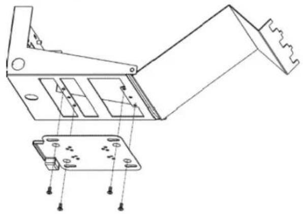
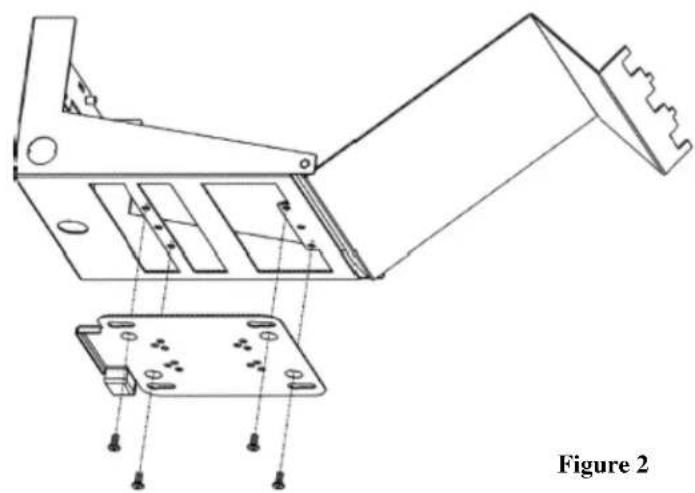
Step 2.1a (Cisco AP with low profile mount) – Use qty 4 screws #8-32 provided to securely fasten the Cisco bracket as shown in Figure 1.
natural_image
Technical line drawing of a mechanical device with exploded view and internal components (no text or symbols)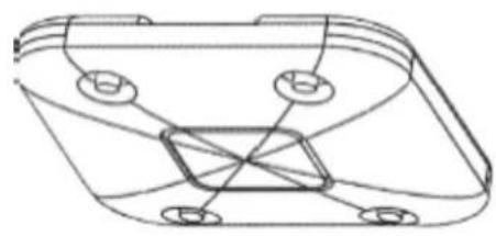
natural_image
Technical line drawing of a mechanical component with mounting holes and internal features (no text or symbols)Step 2.1b (Cisco AP with universal mount) - Use qty 2 screws #8-32 provided to securely fasten the Cisco universal bracket as shown in Figure 1.
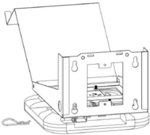
Step 2.1.5 – If a lock is not used, slip the cotter pin provided in place to secure the AP to the Cisco bracket as shown in Figure 3. This will prevent the AP from accidentally being dislodged.
natural_image
Technical line drawing of a mechanical device with internal components and mounting base (no text or symbols)Figure 3
Assembly Instructions Compact Wall Mount
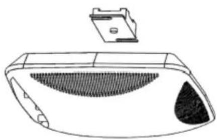
Step 2.2 (Aruba or other T bar mounted AP) – Fasten the AP clip onto the built in T-Bar
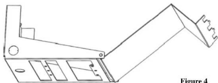
Step 3 –Clamps can be installed by removing the 12 " trade size conduit knock outs if required
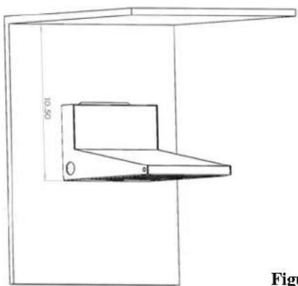
Step 4 – Place the enclosure on the wall where it is to be installed. The enclosure can be mounted directly to a junction box or use the key holes to mount to any wall. Make sure to leave a minimum of 10 1/2" from the bottom of the enclosure to the ceiling so the door can be opened/closed.
natural_image
Technical line drawing of a mechanical bracket component (no text or symbols)Figure 4
natural_image
Technical line drawing of a car front bumper with a plastic housing and internal seating (no text or symbols)Proper screws and wall anchors are the responsibility of the installer.
Step 5 – Run the data and power cables into the enclosure and attach to the AP
Step 6 – Attach AP to enclosure
Step 7 – Close lid until it snaps shut. Installation is now complete.
natural_image
Line drawing of a laptop mounted on a wall, no text or symbols presentFigure 5