8486806 - Computers Raspberry Pi - Free user manual and instructions
Find the device manual for free 8486806 Raspberry Pi in PDF.

| Product Type | Single-board Computer |
| Model | 8486806 (Raspberry Pi 4 Model B) |
| Processor | Broadcom BCM2711, quad-core Cortex-A72 @ 1.5GHz |
| RAM | 2GB, 4GB, or 8GB LPDDR4 (depending on variant) |
| Storage | MicroSD card slot for booting and storage |
| Dimensions | 85.6 x 56.5 x 17 mm |
| Weight | 46 g |
| Power Supply | 5V/3A via USB-C connector |
| Video Output | 2× micro-HDMI (supports up to 4Kp60) |
| Audio Output | 3.5 mm analog audio-video jack |
| USB Ports | 2× USB 3.0, 2× USB 2.0 |
| Ethernet | Gigabit Ethernet |
| Wireless | 2.4/5 GHz dual-band 802.11ac Wi-Fi + Bluetooth 5.0 |
| GPIO | 40-pin GPIO header |
| Operating System | Raspberry Pi OS (Debian-based) or other Linux/Windows IoT Core |
| Maintenance | Keep in a cool, dry place; avoid dust; use a proper case |
| Cleaning | Wipe with a soft, dry cloth; do not use liquids |
| Safety | Use only the recommended power supply; do not expose to water or high temperatures |
| Spare Parts & Repairability | No user-serviceable parts; microSD card replaceable; consider a protective case |
| General Information | Designed by Raspberry Pi Foundation; ideal for education, prototyping, and IoT |
Frequently Asked Questions - 8486806 Raspberry Pi
User questions about 8486806 Raspberry Pi
0 question about this device. Answer the ones you know or ask your own.
Ask a new question about this device
Download the instructions for your Computers in PDF format for free! Find your manual 8486806 - Raspberry Pi and take your electronic device back in hand. On this page are published all the documents necessary for the use of your device. 8486806 by Raspberry Pi.
USER MANUAL 8486806 Raspberry Pi
Rev-0.2, 8-Sept.-2014
The Gertbot is a motor controller board for the Raspberry-Pi. For details how to operate it read the Gertbot manual and/or the Gertbot GUI. This manual describes how to unlock some of the more challenging features of the board.
Contents
Cascade....2
More current for DC motors. 3
More current for Stepper motors....5
Going to DC 10 Amp....5
Going to Stepper 10 Amp. 6
Uploading new software....6
Board Erase....6
Gertbot Advanced Rev 0.2 8-Sept.-2014
Cascade.
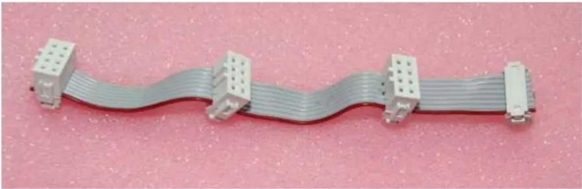
To use two or more boards you need to make a cascade cable. That is a flat cable with up to four 8-pin female headers. This is such a cable:
natural_image
Coiled gray cable with four white connectors, placed on a pink textured surface (no text or symbols visible)The length of the cable depends on how far apart you want to mount the boards. If you stack them using 15mm stand-offs you need 120 mm cable. You also need an 8-pin IDC press connector per board. I put a video on YouTube how to make a press connector a while ago:
http://www.youtube.com/watch?v=sMiRoXY_oZg.
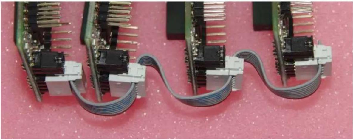
The following picture shows an example how the cable can be connected to four boards.
natural_image
Close-up of four electronic circuit boards with metallic pins and coiled cables, arranged on a pink textured surface (no visible text or symbols)Note that the jumpers on the picture above are wrong. You must give each board a unique ID.
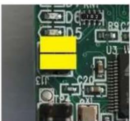
The following diagram shows the ID with the jumpers:
natural_image
Close-up of a green printed circuit board with electronic components and connectors (no readable text or symbols)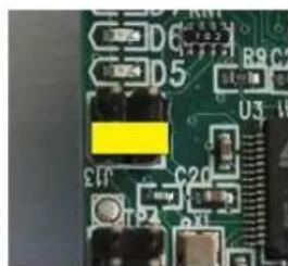
natural_image
Close-up of a green printed circuit board with electronic components and connectors (no readable text or symbols)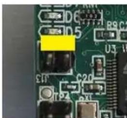
natural_image
Close-up of a green printed circuit board with electronic components and connectors (no readable text or symbols)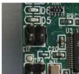
natural_image
Close-up of a green printed circuit board with electronic components and traces (no readable text or symbols)ID=0 ID=1 ID=2 ID=3
More current for DC motors.
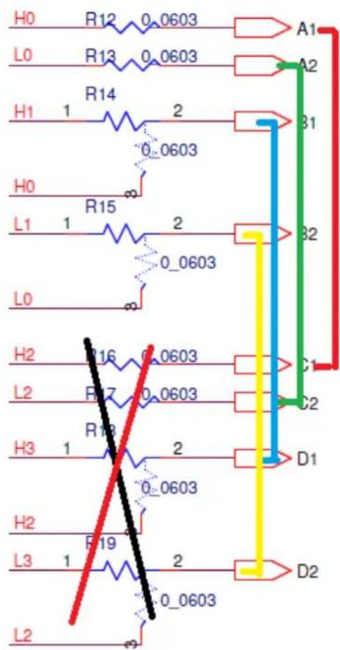
One H-bridge can pass 2.5A. As we have four of them it is possible to combine bridges to allow more then 2.5A. Here is the part of the schematics which deals with the signals we are going to mess about with:
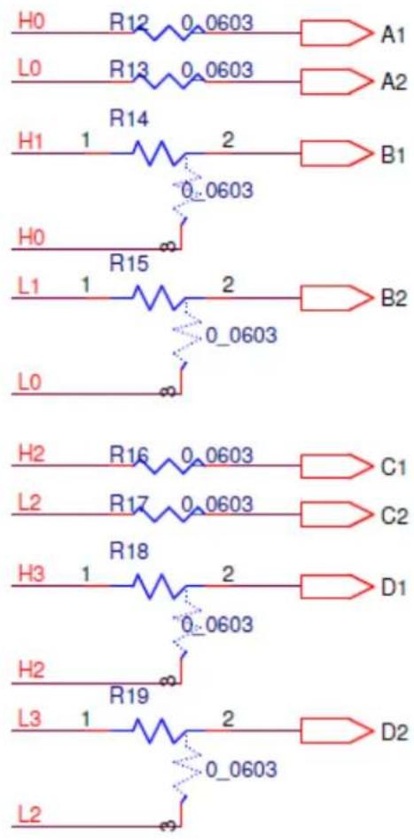
Beware the A1, A2, .. D2 here are NOT the outputs of the bridge on the terminals. These are internal signals on the board.
H0, L0, H1, L1, H2, L2, H3, L3 are signals from the controller. They are going to the H-bridges to control the outputs. Coming from the factory the following connections are present:
H0→A1
L0→A2
H1→B1
L1→B2
H2 C1
L2→C2
H3→D1
L3→D2
To make two bridges work in parallel for a DC motor we have to give them the same control signals. Thus to connect A and B in parallel we need the following connections:
H0→A1 L0→A2
H0→B1
L0→B2
The board has a special layout to make this easy. In this case the board layout looks just like the schematic: Un-solder R14, rotate it 90 degrees and solder it down again:
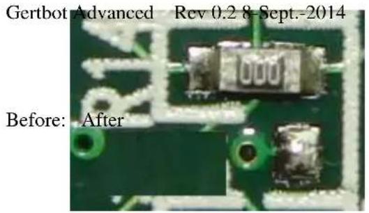
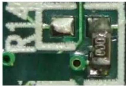
natural_image
Close-up of a green printed circuit board with visible traces and components (no readable text or symbols)The same is valid for R15, R18 and R19. You don't have to re-use the "resistor". You can use a piece of wire as well. The two images below show how I made all four connections. In the top two I re-used the resistors, in the bottom two I used wires.
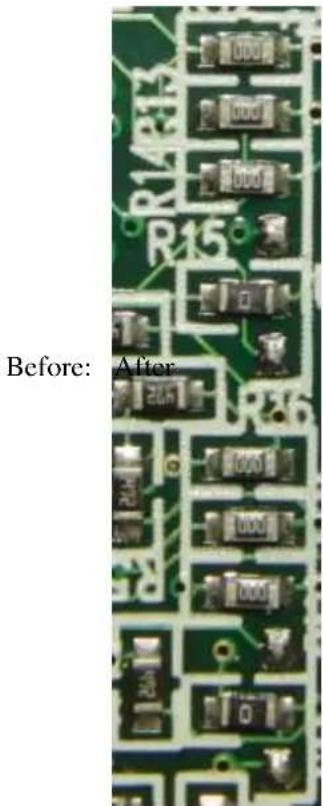
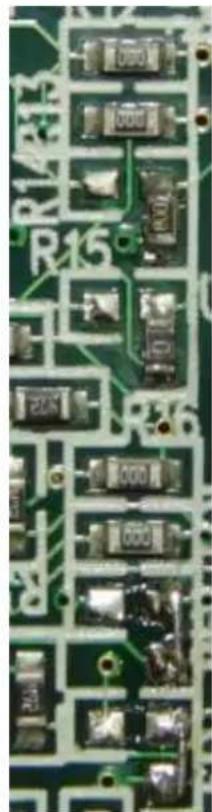
natural_image
Close-up of a green printed circuit board with visible traces and components (no readable text or symbols)This works for DC motors and only if you also parallel up the two outputs. Thus connect the A1 and B1 on the terminals together, you also have to connect A2 and B2 on the terminals together. (The same for C and D).
As H1 and L1 are not connected you can no longer use the motor 1 controls. Again the same for H3 and L3 so the motor 3 can no longer be used.
The current-limiting is per H-bridge so you do not need to make any changes to the current limiting logic. The current will be distributed about even between the two bridges so the current limiter will still kick in if one bridge starts to draw more than 2.5A. As that bridge will stop conducting the full current will try to go through the other bridge and its current detect will kick in as well.
More current for Stepper motors.
I have NOT tried this so this chapter is based on theory. However the theory is simple and it should work.
A stepper motors is controlled with a set of signals: H0, L0, H1, L1. To double the current of a stepper motor you have to parallel up bridge A with C and bridge B with D. Remove R16, R17, R18 and R19. Then make connections like below.
You should set all error channels to ‘stop board if high current detected’. Also you must parallel up the output on the terminals in the identical way: A1 with C1, A2 with C2 etc.
Going to DC 10 Amp.
Nope I have NOT tried this either.
Remove all of R14, R15, R16, R17, R18 and R19. Then Connect H0 (or A1, they are the same) to B1, C1 and D1. Connect L0 to B2, C2 and D2.
Again also connect the outputs in parallel in the right way: A1, B1, C1 and D1 together and A2, C2, B2 and D2 together.
I recommend you set all error channels to 'stop board if high current detected'.
Going to Stepper 10 Amp.
I would not recommend this as you may not have a good ground between the boards.
Therefore I will not describe how to do this. You have to be technical savvy to get this right. That again means you would not need a chapter to tell you how to do this.
If you want to try this don't forget to cross connect the high-current detection circuit too!!! (The “stop all boards if high current detected” may be a bit slow for this).
Uploading new software.
There is a GUI which can be used to upload new software: gb_upload. You normally cannot upload your own software as the code to be uploaded is encrypted and need to pass strict CRC checks before the board will accept it. To upload new code you must have only a single board connected. The procedure is straight forward: Start the gb_upload program, press the 'connect' button. The program will check if there is a single board connected. If so you can browse to a new image and press the 'upload' button.
There is no warranty if the upload goes wrong. Also there is no back-up image. There is a re-flash service but you will have to pay for that.
You also need to remove power and apply it again if you abort the upload procedure.
Board Erase.
The controller on the board has the protection bits set. This means you can NOT connect a debugger and see what is running. Neither can you upload your own code. If you want to program the Gertbot with your own code you are welcome to do so but you must first perform a 'Board Erase'.
A Board Erase will wipe all the code from the board.
Afterwards you will need an Atmel debugger to re-program the device.
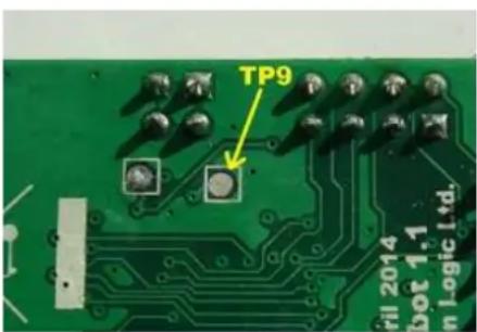
This is how you can erase the board:
- Make sure the board has no power.
- Connect TP9 to a 3V3 pin. For example pin 1 of J10 or pin 17 of J3.
- Apply 5V to the power supply.
- Remove the power supply.
- Remove the TP9 connection.
- Apply 5V to the power supply.
The board is now erased. You can see this from the fact that the four LED's are slightly glowing, but none of them is blinking anymore.