84001 - Émetteur RF Lindy - Free user manual and instructions
Find the device manual for free 84001 Lindy in PDF.

User questions about 84001 Lindy
0 question about this device. Answer the ones you know or ask your own.
Ask a new question about this device
Download the instructions for your Émetteur RF in PDF format for free! Find your manual 84001 - Lindy and take your electronic device back in hand. On this page are published all the documents necessary for the use of your device. 84001 by Lindy.
USER MANUAL 84001 Lindy
Raspberry Pi RF Transmitter
User Manual English
natural_image
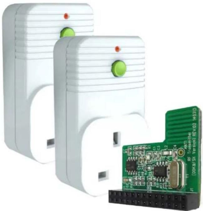
Two white electronic devices with green control knobs next to a green printed circuit board (no visible text or symbols)No. 84001
www.lindy.com
CE
Introduction
Thank you for purchasing this RF controlled Raspberry Pi starter kit. Using this RF transmitter add on board, you can control up to 4 radio controlled sockets from your Raspberry Pi.
The add-on board connects to the row of pins called the GPIO which can be controlled as either input or output lines under the control of software.
We have written a simple program in Python to allow you to switch the remote controlled sockets on and off with a single key press.
Package Contents
■ 1 x RF transmitter add on board
■ 2 x Radio Controlled Sockets
Features
■ Short range radio transmitter
■ Simple plug in installation
■ Up to 10 individual commands
■ Easy software control
■ Ideal learning and experimental tool
- Compatible with 73113 (3 Pack Remote Control Sockets) & 73122 (4 Way Remote Controlled Strip)
Requirements
■ Raspberry Pi Version A or B
- Installed OS: Raspian (or other LINUX OS with Python installed)
Installation
Installing the board
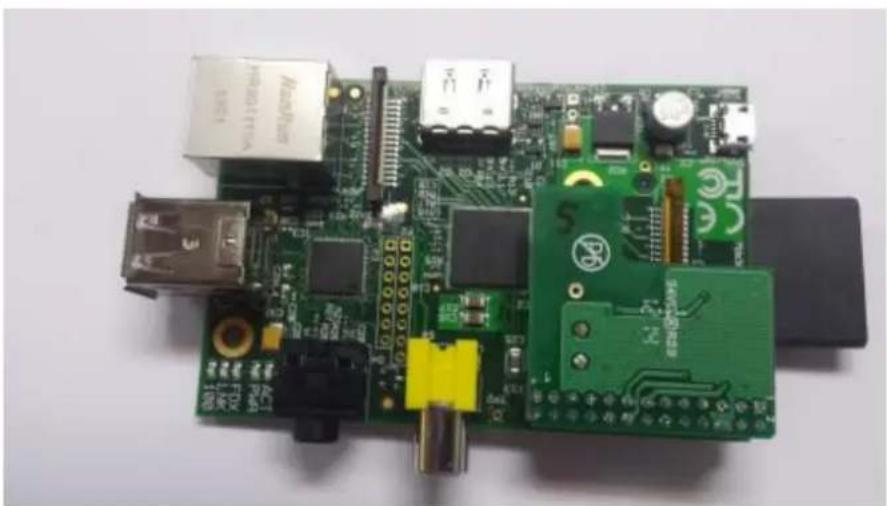
Install the board on to the row of pins as shown below and connect your Raspberry-Pi as normal to a monitor, mouse, keyboard and USB power supply.
natural_image
Close-up of a Raspberry Pi board with various electronic components and connectors (no visible text or symbols)User Manual English
The pin header connects to the add-on board as follows to allow you to control the GPIO lines as outputs to drive the radio frequency transmitter.
Your software will use the outputs on the GPIO connector to drive the add-on board. We have written some code in Python to switch the two sockets on and off.
Each board transmits a frame of information using On-Off-Keying (OOK) which is a basic form of Amplitude Shift Keying (ASK). This frame includes source address (20 bits) and control data (4 bits).

heatmap
GPIO Pin Header Rev 2.0 | Encoder signal D0 | 3V3 | 1 | 2 | 5v | |---|---|---|---|---| | Encoder signal D0 | GPIO2 | 3 | 4 | 5v | | Encoder signal D0 | GPIO3 | 5 | 6 | Ground | | Encoder signal D0 | GPIO4 | 7 | 8 | GPIO14 | | Encoder signal D0 | Ground | 9 | 10 | GPIO15 | | Encoder signal D0 | GPIO17 | 11 | 12 | GPIO18 | | Encoder signal D0 | GPIO27 | 13 | 14 | Ground | | Encoder signal D0 | GPIO22 | 15 | 16 | GPIO23 | | Encoder signal D0 | 3V3 | 17 | 18 | GPIO24 | | Encoder signal D0 | GPIO10 | 19 | 20 | Ground | | Encoder signal D0 | GPIO9 | 21 | 22 | GPIO25 CE modulator enable (Output ON/OFF) | | Encoder signal D0 | GPIO11 | 23 | 24 | GPIO8 | | Encoder signal D0 | Ground | 25 | 26 | GPIO7 | Encoder signal D2 MODSEL mode select signal (OOK/FSK)The source address is randomly selected (so unique for that board), pre-programmed and cannot be changed. The socket will accept commands frames that have the source address that it learns during the learning process described later.

text_image
Preamble A0 - A19 (20 bits - preset) D0 - D3 preamble 1 31 data (H) 3 1 data (L) 1 3 Ick=256clkHere are the pairs of codes using D0-D3 that can be sent to control sockets; we will use socket 1 and socket 2 in the sample program at the end:
| D3 | D2 | D1 | D0 | Meaning | D3 | D2 | D1 | D0 | Meaning |
| 1 | 0 | 1 | 1 | All on | 0 | 0 | 1 | 1 | All off |
| 1 | 1 | 1 | 1 | socket 1 on | 0 | 1 | 1 | 1 | socket 1 off |
| 1 | 1 | 1 | 0 | socket 2 on | 0 | 1 | 1 | 0 | socket 2 off |
| 1 | 1 | 0 | 1 | socket 3 on | 0 | 1 | 0 | 1 | socket 3 off |
| 1 | 1 | 0 | 0 | socket 4 on | 0 | 1 | 0 | 0 | socket 4 off |
The PCB can therefore control a maximum of 4 radio sockets independently. However, more than one socket may be controlled by the same control code.
There are two parts to the transmitter board, the encoder and the modulator:
1) The encoder will accept 4 input signal levels programmed onto 4 of the GPIO lines (D0-D3) as shown above. It will then serialise them on a single line to the modulator part.
2) The modulator transmits the serialised signal. It needs to be programmed in Amplitude- Shift Keying (ASK) mode for the sockets using a GPIO signal. It also needs to be enabled by a separate GPIO signal.
Firstly, we need to install a Python module, RPi.GPIO, to enable software control of the GPIO pins for the Raspberry Pi. Open an LXterminal from the desktop and type the following lines:
sudo apt-get install python-rpi.gpio
Now, open a text editor such as leafpad and type the python code listed at the end called LINDY002-2PI.py into a new file under home/pi. This program will allow us to send coded commands to the sockets to program them and then switch them on and off when the return key on the keyboard is hit.
Controlling the sockets
Launch your program by typing the following command at the prompt in the LXterminal window:
sudo python LINDY002-2PI.py
Then insert one of the radio controlled sockets into a mains wall socket which is switched on. The socket must then be programmed to learn a control code from the transmitter. To do this the socket must be in learning mode indicated by the lamp on the front of the socket housing flashing slowly. If it is not doing this, press and hold the green button on the front of the housing (while the lamp is off), for 5 seconds or more and then release it when the lamp starts to flash at 1 second intervals. Then send a signal to it from you program by hitting the return key. Acceptance will be indicated by a brief quick flashing of the lamp on the housing which will then extinguish. Program one socket first then the others in this way, otherwise they will react to the same signal.
You can then toggle the sockets on and off by hitting the return key. You can also switch them manually on and off by briefly pressing the button on the front housing. You can always reset the socket programming by holding down the green button for 5 seconds or more as mentioned before.
To increase the range of the transmitter you may wish to add an extra antenna to the circuit board. You can do this by soldering a piece of ordinary copper wire 13.5cm long into the hole marked ANT1 on the circuit board.
IMPORTANT: The sockets will need to be inserted into separate mains wall sockets with a physical separation of at least 2 metres to ensure they don't interfere with each other. Do not put into a single extension lead.
Here is the program LINDY002.py
import the required modules
import RPi.GPIO as GPIO import time
# set the pins numbering mode GPIO.setmode(GPIO.BOARD)
# Select the GPIO pins used for the encoder K0-K3 data inputs GPIO.setup(11, GPIO.OUT)
GPIO.setup(15, GPIO.OUT)
GPIO.setup(16, GPIO.OUT)
GPIO.setup(13, GPIO.OUT)
<h1 id="select-the-signal-to-select-askfsk-gpiosetup18-gpioout">Select the signal to select ASK/FSK GPIO.setup(18, GPIO.OUT)</h1>
<h1 id="select-the-signal-used-to-enabledisable-the-modulator-gpiosetup22-gpioout">Select the signal used to enable/disable the modulator GPIO.setup(22, GPIO.OUT)</h1>
<h1 id="disable-the-modulator-by-setting-ce-pin-lo-gpiooutput-22-false">Disable the modulator by setting CE pin lo GPIO.output (22, False)</h1>
<h1 id="set-the-modulator-to-ask-for-on-off-keying">Set the modulator to ASK for On Off Keying</h1>
<h1 id="by-setting-modsel-pin-lo">by setting MODSEL pin lo</h1>
GPIO.output (18, False)
<h1 id="initialise-k0-k3-inputs-of-the-encoder-to-0000">Initialise K0-K3 inputs of the encoder to 0000</h1>
GPIO.output (11, False)
GPIO.output (15, False)
GPIO.output (16, False)
GPIO.output (13, False)
<h1 id="the-onoff-code-pairs-correspond-to-the-hand-controller-codes">The On/Off code pairs correspond to the hand controller codes.</h1>
<h1 id="true-1-false-0">True = '1', False = '0'</h1>
print "OUT OF THE BOX: Plug the Pi Transmitter board into the Raspberry Pi"
print "GPIO pin-header ensuring correct polarity and pin alignment."
print ""
print "The sockets will need to be inserted into separate mains wall sockets."
print "with a physical separation of at least 2 metres to ensure they don't"
print "interfere with each other. Do not put into a single extension lead."
print ""
print "For proper set up the sockets should be in their factory state with"
print "the red led flashing at 1 second intervals. If this is not the case for"
print "either socket, press and hold the green button on the front of the unit"
print "for 5 seconds or more until the red light flashes slowly."
print ""
print "A socket in learning mode will be listening for a control code to be"
print "sent from a transmitter. A socket can pair with up to 2 transmitters"
print "and will accept the following code pairs"
print ""
print "0011 and 1011 all sockets ON and OFF"
print "1111 and 0111 socket 1 ON and OFF"
print "1110 and 0110 socket 2 ON and OFF"
print "1101 and 0101 socket 3 ON and OFF"
print "1100 and 0100 socket 4 ON and OFF"
print ""
print "A socket in learning mode should accept the first code it receives"
print "If you wish the sockets to react to different codes, plug in and"
print "program first one socket then the other using this program."
print ""
print "When the code is accepted you will see the red lamp on the socket"
print "flash quickly then extinguish"
print ""
print "The program will now loop around sending codes as follows when you"
print "hit a key:"
print "socket 1 on"
print "socket 1 off"
print "socket 2 on"
print "socket 2 off"
print "all sockets on"
print "all sockets off"
print "Hit CTL C for a clean exit"
try:
<h1 id="we-will-just-loop-round-switching-the-units-on-and-off">We will just loop round switching the units on and off</h1>
while True:
    raw_input('hit return key to send socket 1 ON code')
    # Set K0-K3
    print "sending code 1111 socket 1 on"
    GPIO.output (11, True)
    GPIO.output (15, True)
    GPIO.output (16, True)
    GPIO.output (13, True)
    # let it settle, encoder requires this
    time.sleep(0.1)
    # Enable the modulator
    GPIO.output (22, True)
    # keep enabled for a period
    time.sleep(0.25)
    # Disable the modulator
    GPIO.output (22, False)

    raw_input('hit return key to send socket 1 OFF code')
    # Set K0-K3
    print "sending code 0111 Socket 1 off"
    GPIO.output (11, True)
    GPIO.output (15, True)
    GPIO.output (16, True)
    GPIO.output (13, False)
    # let it settle, encoder requires this
    time.sleep(0.1)
    # Enable the modulator
    GPIO.output (22, True)
    # keep enabled for a period
    time.sleep(0.25)
    # Disable the modulator
    GPIO.output (22, False)

    raw_input('hit return key to send socket 2 ON code')
    # Set K0-K3
    print "sending code 1110 socket 2 on"
    GPIO.output (11, False)
    GPIO.output (15, True)
    GPIO.output (16, True)
    GPIO.output (13, True)
    # let it settle, encoder requires this
    time.sleep(0.1)
    # Enable the modulator
    GPIO.output (22, True)
    # keep enabled for a period
    time.sleep(0.25)
    # Disable the modulator
    GPIO.output (22, False)

    raw_input(' hit return key to send socket 2 OFF code')
    # Set K0-K3
    print "sending code 0110 socket 2 off"
    GPIO.output (11, False)
    GPIO.output (15, True)
    GPIO.output (16, True)
    GPIO.output (13, False)
    # let it settle, encoder requires this
    time.sleep(0.1)
    # Enable the modulator
    GPIO.output (22, True)
    # keep enabled for a period
    time.sleep(0.25)
    # Disable the modulator
    GPIO.output (22, False)
raw_input('hit return key to send ALL ON code')
<h1 id="set-k0-k3">Set K0-K3</h1>
print "sending code 1011 ALL on"
GPIO.output (11, True)
GPIO.output (15, True)
GPIO.output (16, False)
GPIO.output (13, True)
<h1 id="let-it-settle-encoder-requires-this">let it settle, encoder requires this</h1>
time.sleep(0.1)
<h1 id="enable-the-modulator">Enable the modulator</h1>
GPIO.output (22, True)
<h1 id="keep-enabled-for-a-period">keep enabled for a period</h1>
time.sleep(0.25)
<h1 id="disable-the-modulator">Disable the modulator</h1>
GPIO.output (22, False)

raw_input('hit return key to send ALL OFF code')
<h1 id="set-k0-k3-2">Set K0-K3</h1>
print "sending code 0011 All off"
GPIO.output (11, True)
GPIO.output (15, True)
GPIO.output (16, False)
GPIO.output (13, False)
<h1 id="let-it-settle-encoder-requires-this-2">let it settle, encoder requires this</h1>
time.sleep(0.1)
<h1 id="enable-the-modulator-2">Enable the modulator</h1>
GPIO.output (22, True)
<h1 id="keep-enabled-for-a-period-2">keep enabled for a period</h1>
time.sleep(0.25)
<h1 id="disable-the-modulator-2">Disable the modulator</h1>
GPIO.output (22, False)
<h1 id="clean-up-the-gpios-for-next-time">Clean up the GPIOs for next time</h1>
except KeyboardInterrupt:
    GPIO.cleanup()
CE Certification
This equipment complies with the requirements relating to Electromagnetic Compatibility Standards EN55022/EN55024 and the further standards cited therein. It must be used with shielded cables only. It has been manufactured under the scope of RoHS compliance.

LINDY Electronics Ltd.
Sadler Forster Way
Teesside Industrial Estate
Thornaby, Stockton-on-Tees
TS17 9JY, England
Declaration of Conformity
LINDY Part Number: 84001
Description: Raspberry Pi RF Board with 2 x RF Sockets
We, LINDY Electronics LTD, hereby declare that the above product is in conformity with the EU Directive 2004/108/EC (Electromagnetic Compatibility Directive), 2006/95/EC (Low Voltage Directive), 2009/125/EC (ErP Directive) and 2011/65/EU (Restriction of the use of certain hazardous substances - RoHS).
The following standards were used to evaluate the product for electromagnetic compatibility:
Safety: BS5733
EN 61058-1
EMC & Radio: EN 300 220-2
EN 301489-01
EN 301489-03
Energy: IEC62301:2005
And is in accordance with the following Directive(s):
2006/95/EC The Low Voltage Directive
2004/108/EC The Electromagnetic Compatibility Directive
1999/5/EC R&TTE Directive
2002/96/EC Waste Electrical and Electronic Equipment (WEEE) Directive
2011/65/EU Restriction of the Use of Certain Hazardous Substances (RoHS) Directive EU
2009/125/EC ErP Directive 2009/125/EC
Date: 16 September 2014
Signature:

Name: Darren N. Casey
Position: Managing Director, LINDY Electronics LTD
LINDY Supplier Office Reference: 24 ^th June 2014
L/PF/103b/DOC/EMC-LVD-ErP-RoHS
Issue 3


WEEE (Waste of Electrical and Electronic Equipment), Recycling of Electronic Products
Europe, United Kingdom
In 2006 the European Union introduced regulations (WEEE) for the collection and recycling of all waste electrical and electronic equipment. It is no longer allowable to simply throw away electrical and electronic equipment. Instead, these products must enter the recycling process.
Each individual EU member state has implemented the WEEE regulations into national law in slightly different ways. Please follow your national law when you want to dispose of any electrical or electronic products. More details can be obtained from your national WEEE recycling agency.