15-AH28B - NAS TRENDNET - Free user manual and instructions
Find the device manual for free 15-AH28B TRENDNET in PDF.

User questions about 15-AH28B TRENDNET
0 question about this device. Answer the ones you know or ask your own.
Ask a new question about this device
Download the instructions for your NAS in PDF format for free! Find your manual 15-AH28B - TRENDNET and take your electronic device back in hand. On this page are published all the documents necessary for the use of your device. 15-AH28B by TRENDNET.
USER MANUAL 15-AH28B TRENDNET
natural_image
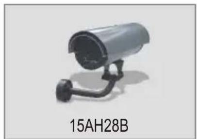
Exterior view of a black cylindrical security camera mounted on a stand (no text or symbols visible)Table of Contents
English 1
- Prepare for Installation 1
- Install Hardware 2
Troubleshooting 9
English UG
1. Prepare for Installation
Thank you for purchasing the TRENDnet 15AH28B Outdoor Internet Camera Server Housing with Fan/Heater.
This guide will help you set-up your Outdoor Internet Camera Server Housing. Following the installations should be quick and easy. If you run into problems, please refer to the Troubleshooting section. If you need further technical support, please visit www.TRENDNET.com or call technical support by phone.
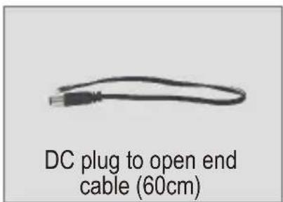
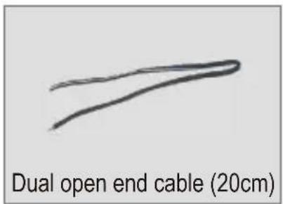
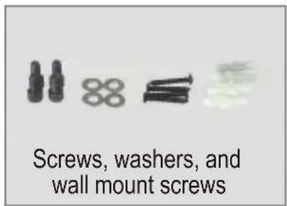
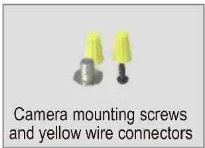
Verify Package Contents
Please make sure you have everything in the box:
natural_image
Exterior view of a security camera with a mounted cable (no text or symbols visible)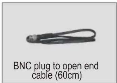
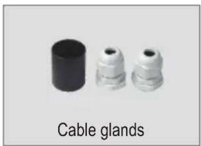
natural_image
Three white plastic connectors with black caps, labeled 'Cable glands' below (no other text or symbols)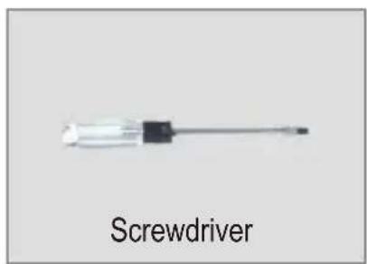
2. Install Hardware
- Depress the levers to unlatch the roof of the camera enclosure, and pull the roof upward.
natural_image
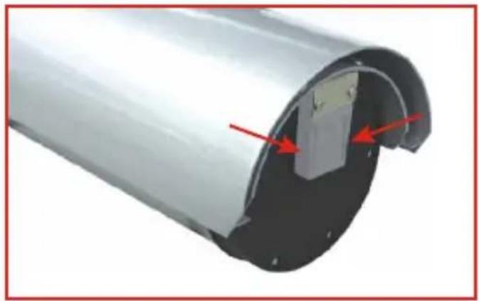
Cross-sectional view of a cylindrical mechanical component with red arrows indicating features (no text or symbols)- Unscrew the metal bracket from the camera enclosure.
natural_image
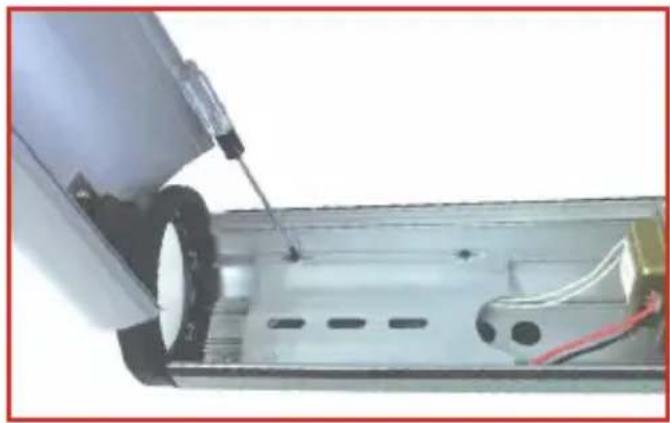
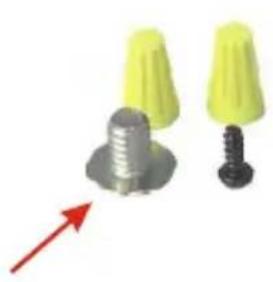
Close-up of a mechanical device with a tool inserted, showing internal components and wiring (no visible text or symbols)- Use the following screw to mount the metal bracket onto the base of the IP Camera.
natural_image
Two yellow cone-shaped objects with metallic bases and a black screw, one with a red arrow pointing downward (no text or symbols)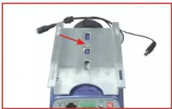
natural_image
Close-up of a device with a red arrow pointing to a purple button, connected to cables and ports (no visible text or symbols)- Take the assembly in step 3, and mount the assembly inside the camera enclosure.
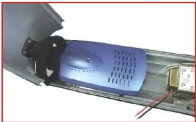
natural_image
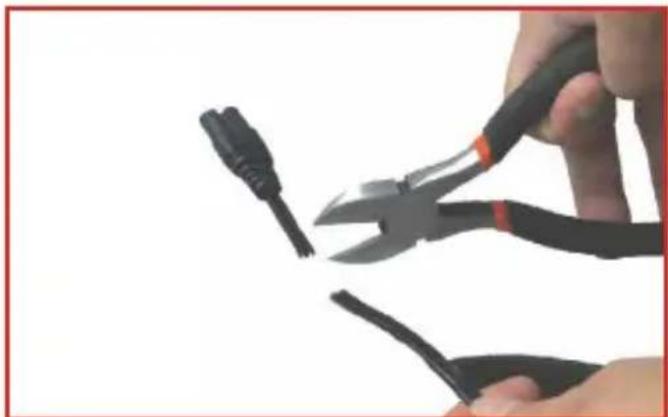
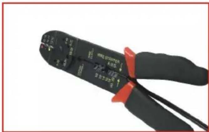
Close-up of a blue industrial fan or motor component with visible wiring and components (no text or symbols)- Caution: Before cutting any power cord, make sure that the power cord is NOT PLUGGED into an electrical source. Now take a power cord with a two-prong plug and cut the wire.
natural_image
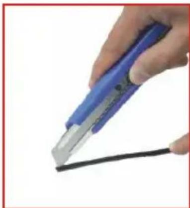
Close-up of hands using pliers to cut a cable (no text or symbols visible)- Use a precision knife or a sharp object to split the wire in two halves.
natural_image
Hand holding a blue and silver tool applying material to a black cable (no text or symbols visible)
natural_image
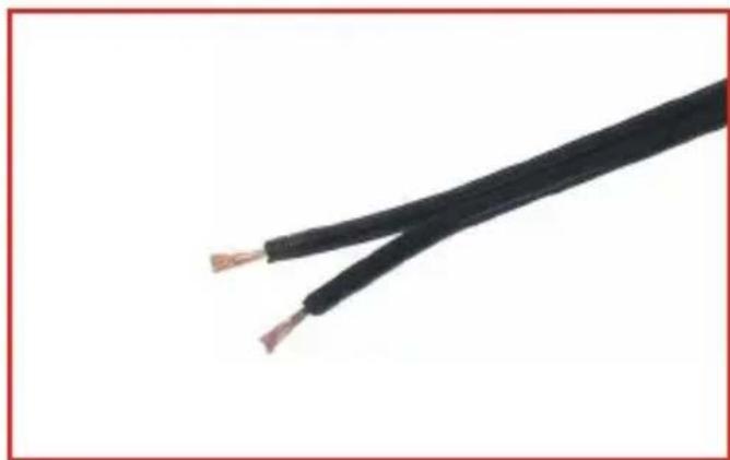
Close-up of a hand using a blue tool to cut a black cable (no text or symbols visible)- Peel the plastic sheath to expose the copper wiring. It is recommended that you use a wire stripper to remove the plastic sheath effectively.
- You should have two halves of exposed copper wire as shown below.
natural_image
Close-up of a black electrical cable with exposed copper wires (no text or symbols)- Turn the camera enclosure upside down to remove one of the rubber stoppers. This will give you an opening for your power cord, antenna cable, or network patch cable.
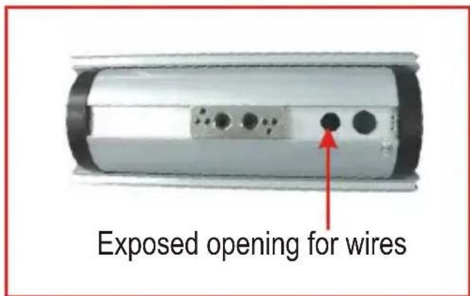
- Run your power cord, network patch cable or antenna cable through the opening of the camera enclosure.
natural_image
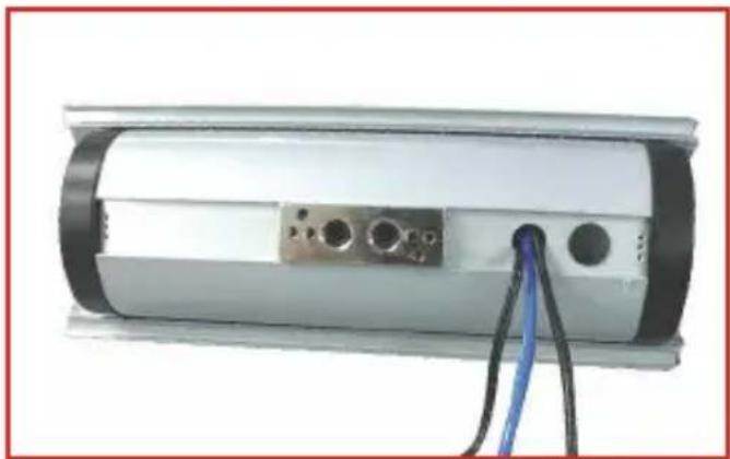
Exterior view of a cylindrical electronic device with black and white casing, connected to a blue cable (no visible text or symbols)Note: For security purposes, attach the metal arm assembly to the camera enclosure and run the wires through the metal arm assembly. Please refer to the camera enclosure's attachment for setup details.
- Pair one half of the power cable with the red terminal of the enclosure's power supply.
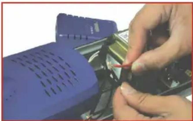
natural_image
Close-up of hands using a handheld device to adjust or install a component (no visible text or symbols)- Place the yellow wire connector over the assembly in step 11, and twist the wire connector clockwise to secure the contact between the wired pair.
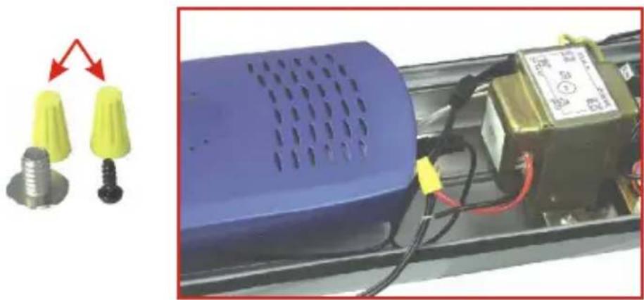
natural_image
Close-up of a blue electronic device with yellow and black components, connected to an electrical terminal block (no visible text or symbols)- Pair the other half of the power cable with the black terminal of the enclosure's power supply.
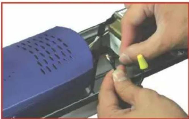
natural_image
Close-up of hands installing a component into a blue plastic device (no visible text or symbols)- Place the yellow wire connector over the assembly in step 13, and twist the wire connector clockwise to secure the contact between the wired pair.
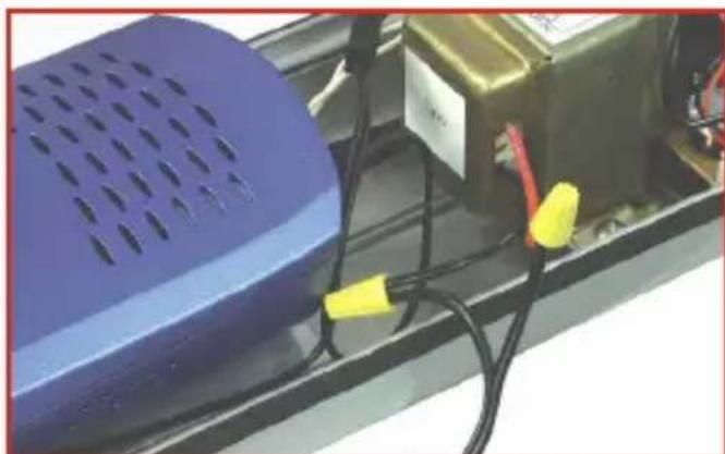
natural_image
Close-up of a blue perforated speaker with black and yellow cables, next to an industrial control panel (no visible text or symbols)- Take the DC plug and connect the terminals into the DC box of the camera enclosure.
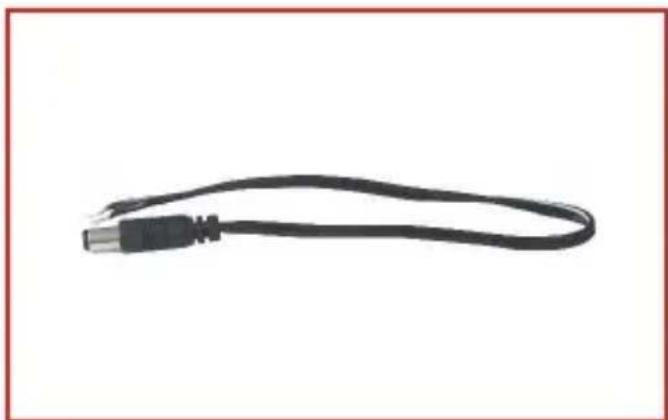
natural_image
Black cable with metallic connector, isolated on white background (no text or symbols)- Turn the screw counter-clockwise to insert the DC Plug's terminal into the DC box. Insert one end of the DC plug terminal into the positive side of the DC box. Insert the other end of the DC plug terminal into the negative side of the DC box.
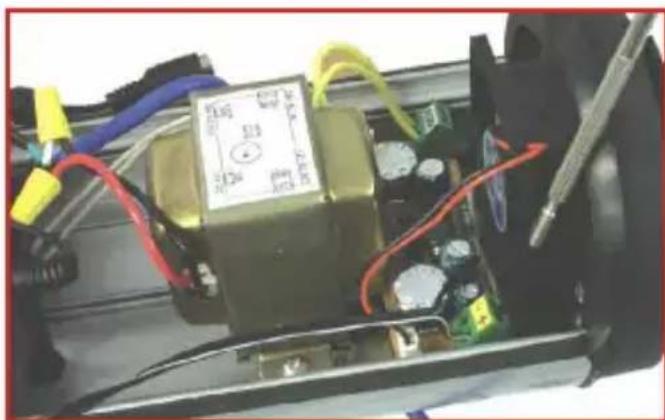
natural_image
Close-up of an electronic device with visible wiring, capacitors, and a multimeter (no readable text or symbols)- Secure the contact between the DC plug terminal and DC box by turning the screw clockwise.
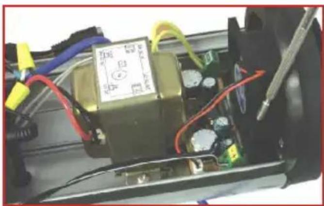
natural_image
Interior view of an electronic device with visible wiring, components, and a central control panel (no readable text or symbols)- Connect the DC plug with the IP Camera's power connector.
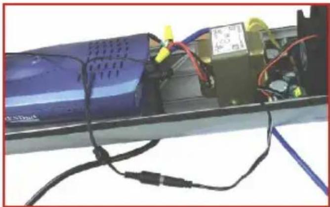
natural_image
Close-up of a blue electronic device with attached wires and components, no visible text or symbols- Make sure all internal wires are inside the camera enclosure, and carefully close the lid. Then plug in the two-prong cord into any power outlet. The camera's LEDs should immediately turn on.
Your hardware installation is now complete.
Q1. What do I do if the LEDs on my camera remain off?
A1. Make sure that the power adapter is connected to a power outlet and that your power outlet is receiving power.
Q2. My power outlet is receiving power, but my camera will not turn on. What do I do next?
A2. Unplug the power cord from your power outlet, and open the camera enclosure. Double check your power supply's connections. Make sure that the yellow connectors are twisted in a clockwise direction to tighten the contacts between your power cord terminals and power supply. It's possible that these wires are not getting any contact, so be sure that the yellow wire connectors are turned in a clockwise direction.
Q3. The terminals between my power supply and power cord are making contact, but I still cannot turn on my camera. What else can I do?
A3. Double-check the connection between the DC plug and DC box. Make sure that the DC plug's terminals are properly inserted into the DC box, and that the contact is securely connected to the DC box. Tighten the screws on the DC box by turning the screw clockwise. Tug the wire to make sure that the DC plug terminals are tightly connected to the DC box.
Q4. My camera is receiving power, but I cannot access my camera's web configuration utility. What should I do?
A4. If you are using a wired IP camera, double check your hardware settings. Make sure that your network patch cable is connected to your camera and switch. Make sure that the network patch cable is not faulty, and that your switch is operating properly. If you are using a wireless camera, make sure that your antenna connection is properly connected to your camera's antenna connector. Double-check your antenna's position, and make sure that your antenna is getting direct line of site with your wireless access point.
If you have any questions regarding the 15AH28B, please contact Trendware Technical Support Department.
Certifications
This equipment has been tested and found to comply with FCC and CE Rules. Operation is subject to the following two conditions:
(1) This device may not cause harmful interference.
(2) This device must accept any interference received.
Including interference that may cause undesired operation.

NOTE: THE MANUFACTURER IS NOT RESPONSIBLE FOR ANY RADIO OR TV INTERFERENCE CAUSED BY UNAUTHORIZED MODIFICATIONS TO THIS EQUIPMENT. SUCH MODIFICATIONS COULD VOID THE USER'S AUTHORITY TO OPERATE THE EQUIPMENT.
Limited Warranty
TRENDware warrants its products against defects in material and workmanship, under normal use and service, for the following lengths of time from the date of purchase.
Wireless Products 3 Years Warranty
If a product does not operate as warranted above during the applicable warranty period, TRENDware shall, at its option and expense, repair the defective product or part, deliver to customer an equivalent product or part to replace the defective item, or refund to customer the purchase price paid for the defective product. All products that are replaced will become the property of TRENDware. Replacement products may be new or reconditioned.
TRENDware shall not be responsible for any software, firmware, information, or memory data of customer contained in, stored on, or integrated with any products returned to TRENDware pursuant to any warranty.
There are no user serviceable parts inside the product. Do not remove or attempt to service the product by any unauthorized service center. This warranty is voided if (i) the product has been modified or repaired by any unauthorized service center, (ii) the product was subject to accident, abuse, or improper use (iii) the product was subject to conditions more severe than those specified in the manual.
Warranty service may be obtained by contacting TRENDware office within the applicable warranty period for a Return Material Authorization (RMA) number, accompanied by a copy of the dated proof of the purchase. Products returned to TRENDware must be pre-authorized by TRENDware with RMA number marked on the outside of the package, and sent prepaid, insured and packaged appropriately for safe shipment.
WARRANTIES EXCLUSIVE: IF THE TRENDWARE PRODUCT DOES NOT OPERATE AS WARRANTED ABOVE, THE CUSTOMER'S SOLE REMEDY SHALL BE, AT TRENDWARE'S OPTION, REPAIR OR REPLACEMENT. THE FOREGOING WARRANTIES AND REMEDIES ARE EXCLUSIVE AND ARE IN LIEU OF ALL OTHER WARRANTIES, EXPRESSED OR IMPLIED, EITHER IN FACT OR BY OPERATION OF LAW, STATUTORY OR OTHERWISE, INCLUDING WARRANTIES OF MERCHANTABILITY AND FITNESS FOR A PARTICULAR PURPOSE. TRENDWARE NEITHER ASSUMES NOR AUTHORIZES ANY OTHER PERSON TO ASSUME FOR IT ANY OTHER LIABILITY IN CONNECTION WITH THE SALE, INSTALLATION MAINTENANCE OR USE OF TRENDWARE'S PRODUCTS.
TRENDWARE SHALL NOT BE LIABLE UNDER THIS WARRANTY IF ITS TESTING AND EXAMINATION DISCLOSE THAT THE ALLEGED DEFECT IN THE PRODUCT DOES NOT EXIST OR WAS CAUSED BY CUSTOMER'S OR ANY THIRD PERSON'S MISUSE, NEGLECT, IMPROPER INSTALLATION OR TESTING, UNAUTHORIZED ATTEMPTS TO REPAIR OR MODIFY, OR ANY OTHER CAUSE BEYOND THE RANGE OF THE INTENDED USE, OR BY ACCIDENT, FIRE, LIGHTNING, OR OTHER HAZARD.
LIMITATION OF LIABILITY: TO THE FULL EXTENT ALLOWED BY LAW TRENDWARE ALSO EXCLUDES FOR ITSELF AND ITS SUPPLIERS ANY LIABILITY, WHETHER BASED IN CONTRACT OR TORT (INCLUDING NEGLIGENCE), FOR INCIDENTAL, CONSEQUENTIAL, INDIRECT, SPECIAL, OR PUNITIVE DAMAGES OF ANY KIND, OR FOR LOSS OF REVENUE OR PROFITS, LOSS OF BUSINESS, LOSS OF INFORMATION OR DATE, OR OTHER FINANCIAL LOSS ARISING OUT OF OR IN CONNECTION WITH THE SALE, INSTALLATION, MAINTENANCE, USE, PERFORMANCE, FAILURE, OR INTERRUPTION OF THE POSSIBILITY OF SUCH DAMAGES, AND LIMITS ITS LIABILITY TO REPAIR, REPLACEMENT, OR REFUND OF THE PURCHASE PRICE PAID, AT TRENDWARE'S OPTION. THIS DISCLAIMER OF LIABILITY FOR DAMAGES WILL NOT BE AFFECTED IF ANY REMEDY PROVIDED HEREIN SHALL FAIL OF ITS ESSENTIAL PURPOSE.
Governing Law: This Limited Warranty shall be governed by the laws of the state of California.
AC/DC Power Adapter, Cooling Fan, and Power Supply carry a 1 Year Warranty
TRENDnet TRENDware, USA
What's Next in Networking
Product Warranty Registration
Please take a moment to register your product online. Go to TRENDware's website at http://www.TRENDNET.com
TRENDnet Technical Support
| US/Canada Support Center | European Support Center |
| ContactTelephone: 1(310) 626-6252Fax: 1(310) 626-6267Email: support@trendnet.comTech Support Hours7:30am - 6:00pm Pacific Standard TimeMonday - Friday | ContactTelephoneDeutsch : +49 (0) 6331 / 268-460Français : +49 (0) 6331 / 268-4610800-907-161 (numéro vert)Español : +49 (0) 6331 / 268-462English : +49 (0) 6331 / 268-463Italiano : +49 (0) 6331 / 268-464Dutch : +49 (0) 6331 / 268-465Fax: +49 (0) 6331 / 268-466Tech Support Hours8:00am - 6:00pm Middle European TimeMonday - Friday |
TRENDware International, Inc.
3135 Kashiwa Street. Torrance, CA 90505
http://www.TRENDNET.com