TW-H6W1IR - NAS TRENDNET - Free user manual and instructions
Find the device manual for free TW-H6W1IR TRENDNET in PDF.

User questions about TW-H6W1IR TRENDNET
0 question about this device. Answer the ones you know or ask your own.
Ask a new question about this device
Download the instructions for your NAS in PDF format for free! Find your manual TW-H6W1IR - TRENDNET and take your electronic device back in hand. On this page are published all the documents necessary for the use of your device. TW-H6W1IR by TRENDNET.
USER MANUAL TW-H6W1IR TRENDNET
Copyright ©1999 TRENDware
No part of this publication may be reproduced in any form or by any means or used to make any derivative such as translation, transformation, or adaptation without permission TRENDware, as stipulated by the United States Copyright Act of 1976.
Trademarks
TRENDnet is a registered trademark of TRENDware.
All other trademarks belong to their respective owners.
Table of Contents
INTRODUCTION....1
Product Features....2
Applications for your TW-H6W1IR....5
Internet Access 5
Network Address Translation (NAT)......5
LAN-to-LAN Enterprise Connections....5
Telecommuting Server....5
What This Manual Covers....6
What This Manual Doesn't Cover....7
Other Resources....7
Packing List 8
Additional Installation Requirements....8
INSTALLATION 10
Ordering Your ISDN Line....10
The TW-H6W1IR Front Panel....11
The TW-H6W1IR Rear Panel....12
Telephone Features....13
Installation and Initial Configuration....14
A Warning on Connection Cables 15
Step 1 - Setting up the Console .... 15
Step 2 - Connecting the Console to the Router .... 16
Step 3 - Connecting an ISDN Line to the Router .... 17
Step 4 - Connecting a Telephone or Fax Machine to the Router....17
Step 5 - Connecting Ethernet Cables to the Router....18
Step 6 - Powering Up Devices for Initial Configuration....20
Step 7 - Initial Configuration of the Router....21
Step 7 - Configuring the LAN Port....22
Step 8 – Plugging in All Devices....24
CONFIGURATION AND MANAGEMENT 26
Console Program Main Menu 27
System Information....28
Interface Configuration....30
LAN Sub-menu....31
ISDN Sub-menu....32
Network Configuration....35
IP Stack Configuration....35
IP Static Route....40
IP Networking....42
Router Advertisement....42
SNMP Agent Configuration....43
SNMP Community Configuration....44
SNMP Trap Manager....45
SNMP Authenticated Trap 46
Advanced Functions....47
Remote Access Configuration....47
DHCP Configuration 61
Filter Configuration....65
Multiple Home Configuration....72
Static ARP 74
NAT Configuration....76
Configure NAPT for Special Ap[plication]s....92
Telnet/Discovery Enable....95
DNS Configuration 96
Radius Configuration 98
PPP Configuration 100
Admin[istration] Configuration....106
System Maintenance....107
System Status 107
Statistics....108
Log and Trace....114
Diagnostic 117
Software Update....123
System Restart....124
Factory Reset....124
System Settings Backup/Restore....124
PROM SYSTEM CONFIGURATION....126
System Configuration 127
TCP/IP Parameters Configuration 128
System Reset 129
Software Update....129
EEPROM Factory Reset 132
Execute Bootload 132
USING TELNET 133
Telnet Configuration.... 133
Using Telnet via LAN....133
Using Telnet via ISDN.... 134
System Timeout....134
USING RADIUS AUTHENTICATION....135
Installing a RADIUS Server.... 135
Configuring the TW-H6W1IR for RADIUS Authentication.... 135
Adding Users to the RADIUS Database 137
APPENDIX A - TROUBLESHOOTING....138
Some Common Problems With the TW-H6W1IR.... 138
None of the LEDs are on when you power up the router.... 138
Connecting the RS-232 cable, cannot access the console program 138
Problems With the ISDN Line.... 139
Problems with the LAN Interface.... 139
Can't PING any station on the LAN 139
APPENDIX B - IP CONCEPTS....141
IP Addresses....141
IP Network Classes .... 142
Subnet Mask....143
APPENDIX C - IP PROTOCOL AND PORT NUMBERS ..... 145
IP Protocol Numbers....145
IP Port Numbers 145
APPENDIX D - TECHNICAL SPECIFICATIONS ....147
APPENDIX E – COUNTRY ID NUMBERS .... 149
APPENDIX F - CONFIGURATION FILE....150
Configuration File Example 151
INDEX 153
Introduction
Congratulations on your purchase of a TRENDnet TW-H6W1IR ISDN router with integrated Ethernet hub and ISDN T/A. No larger than an ordinary modem, your router offers inexpensive yet complete telecommunications and internetworking solutions for your home or branch office. It is ideal for everything from Internet browsing to receiving calls from Remote Dial-in Users and making connections to other LANs via Remote Nodes.
Distinguishing features of the TW-H6W1IR include support for a full range of networking protocols including TCP/IP (Transmission Control Protocol/Internet Protocol, also known as IP) and Transparent Bridging.
This complete solution also includes remote dial-in user support, an Internet single-user account (Network Address Translation) option, extensive network management capabilities, and solid security features.
Product Features
The TW-H6W1IR router is packed with features that give it the flexibility to provide a complete networking solution for almost any small to medium-sized office environment.
Ease of Installation
Your TW-H6W1IR is a self-contained unit that is quick and easy to install. Physically, it resembles an external modem; however, it is a combination ISDN router and 10 Mbps Ethernet hub, and it uses twisted-pair Ethernet cables to connect to the host network.
Built-in Hub
As a 10 Mbps Ethernet hub, your TW-H6W1IR provides six ports for connecting standard Ethernet devices. Five ports are designed for connecting network end nodes—single-user computers, servers, bridges, other routers, etc.—through standard “straight-through” twisted-pair cables; the sixth is wired for making an “uplink” connection to another hub or switch through the same type of straight-through cable used to connect end nodes.
ISDN Basic Rate Interface (BRI)
Using a standard S/T the TW-H6W1IR supports DSS1 ISDN switches. The two ISDN B-channels can be used independently for two destinations, or they can be bundled together for one high-bandwidth connection supporting bandwidth-on-demand.
ISDN Leased Line
If the router is set up for an ISDN leased line, it can automatically initialize the leased-line connection each time it is powered up.
Standard Phone Jacks
The router is equipped with two standard phone jacks for connecting telephones, fax machines, or modems. This allows the ISDN line to be used for voice as well as data calls.
Dial On Demand
The Dial On Demand feature allows a TW-H6W1IR to automatically place a call to a Remote Node whenever there is traffic coming from any workstation on the LAN (Local Area Network) to that remote site.
Bandwidth On Demand
Your TW-H6W1IR supports bandwidth up to 128 kps over a single ISDN BRI line. It incorporates MLPPP (Multi-Link PPP) to bundle two B channels over a BRI line. In addition, the router dynamically allocates bandwidth between the two B channels, increasing or decreasing bandwidth as needed to allow for greater efficiency in data transfer. It supports BAP (Bandwidth Allocation Protocol) and BACP (Bandwidth Allocation Control Protocol) to manage the number of links in the multi-link bundle.
Full Network Management
The TW-H6W1IR incorporates SNMP (Simple Network Management Protocol) support and menu-driven network management via an RS-232 or Telnet connection.
RADIUS (Remote Authentication Dial In User Service)
The RADIUS feature allows you to use a central external Unix or NT-based server to support thousands of users.
PPP Security
The TW-H6W1IR supports PAP (Password Authentication Protocol) and CHAP (Challenge Handshake Authentication Protocol).
RIP-1/RIP-2
Your TW-H6W1IR supports both RIP-1 and RIP-2 (Routing Information Protocol versions 1 and 2) exchanges with other routers.
DHCP Support (Dynamic Host Configuration Protocol)
DHCP (Dynamic Host Configuration Protocol) allows IP addresses to be automatically and dynamically assigned to hosts on your network.
Data Compression
The TW-H6W1IR incorporates Stac data compression and CCP (Compression Control Protocol).
Networking Compatibility
The TW-H6W1IR is compatible with remote access products from other companies such as Ascend, Cisco, and 3Com. Furthermore, they support Microsoft Windows 95 and Windows NT remote access capability.
Applications for your TW-H6W1IR
Some applications for the TW-H6W1IR include:
Internet Access
Your TW-H6W1IR supports TCP/IP protocol, which is the language used for the Internet. It is also compatible with access servers manufactured by major vendors such as Cisco and Ascend.
Network Address Translation (NAT)
For small office environments, the TW-H6W1IR allows multiple users on the LAN to access the Internet concurrently through a single Internet account. This provides Internet access to everyone in the office for the price of a single user.
NAT address mapping can also be used to link two IP domains via a LAN-to-LAN connection.
LAN-to-LAN Enterprise Connections
The TW-H6W1IR can dial to or answer calls from another remote access router connected to a different LAN. The TW-H6W1IR supports TCP/IP and has the capability to bridge any Ethernet protocol.
Telecommuting Server
The TW-H6W1IR allows Remote Dial-in Users to dial in and gain access to your LAN. This feature enables users that have workstations
with remote access capabilities, e.g., Windows 95, to dial in using an ISDN terminal adapter (TA) to access the network resources without physically being in the office.
What This Manual Covers
This manual is divided into eleven parts.
Chapter One, Introduction, describes many of the technologies implemented in the TW-H6W1IR as well as product features, etc. TW-H6W1IR to operate on your LAN.
Chapter Two, Installation, is designed as a step-by-step guide to installing the router.
Chapter Three, Configuration and Management, provides detailed explanations for the console program that is used to setup and configure the router.
Chapter Four, PROM System Configuration, provides information on the PROM program, an abbreviated version of the console program that is used to download new software into the router in case of problems with the console program.
Chapter Five, Using Telnet, describes how to setup and use telnet to configure the router.
Chapter Six, Using RADIUS Authentication, describes how to setup and use a RADIUS server to manage user authentication and centralize passwords.
Appendix A, Troubleshooting, describes some common problems setting up the router and suggests solutions.
Appendix B, IP Concepts, gives detailed explanations and recommendations for setting up an IP network on your LAN.
Appendix C, IP Protocol and Port Numbers, lists many commonly used IP settings.
Appendix D, Technical Specifications, a list of specifications about the TW-H6W1IR ISDN router.
Appendix E, Country ID Numbers, lists country ID numbers which must be entered when setting up the ISDN line on the router. These numbers have no relation to the International Country Codes used by your telephone company.
Regardless of the application, it is important that you follow the steps outlined in Chapter 2, Installation, to correctly connect your TW-H6W1IR to your LAN. You can then refer to other chapters of the manual depending on your specific installation requirements.
What This Manual Doesn't Cover
This manual assumes that you know how to use your computer and are familiar with your communications software. If you have questions about using either one, refer to the manual for the product.
Other Resources
For more information about your TW-H6W1IR check the following sources:
? ?Quick Installation Guide.
? ?Support disk containing RouteMan, a Windows-based configuration program used to set up and configure the router.
Packing List
Before you proceed further, check all items you received with your TW-H6W1IR against this list to make sure nothing is missing. The complete package should include:
? ?One TW-H6W1IR ISDN router.
? ?One power adapter.
? ?One RS-232 cable.
? ?One unshielded twisted-pair (UTP) cable.
? ?One Quick Installation Guide.
? ?This User's Guide (on diskette).
Additional Installation Requirements
In addition to the contents of your package, there are other hardware and software requirements you need before you can install and use your router. These requirements include:
? ?An ISDN line.
? ?Ethernet connection(s) to your computer(s).
? ?A computer equipped with an RS-232 port and communications software configured to the following parameters:
?? VT100 terminal emulation.
?? 9600 baud.
?? No parity, 8 data bits, 1 stop bit.
After the router has been successfully connected to your network, you can make future changes to the configuration using a Telnet client application.
Installation
This chapter outlines how to connect your TW-H6W1IR to your LAN and ISDN line. Refer to the diagrams below to identify all of the ports on your device when you make connections.
Ordering Your ISDN Line
If you do not have an ISDN line installed already, we suggest that you order it from your telephone company as soon as possible to avoid the long waiting period common when ordering a new line. Use the information in this section to place the order. If you have already installed your ISDN line, you can check the following section to make sure that you can use all the features of your TW-H6W1IR.
- Contact your local telephone company's ISDN Ordering Center.
- Make sure DSS1 switches are available since these are the only switch types currently supported by the TW-H6W1IR.
- When the telephone company installs your ISDN line, be sure to obtain the following information:
?? ISDN switch type.
?? ISDN telephone number(s).
The TW-H6W1IR Front Panel
Names and descriptions of your router's front panel LEDs are given below:
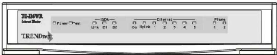
POWER— Comes on as soon as you connect the router to the power adapter and plug the power adapter into a suitable AC outlet.
TEST— Should be blinking if the router is functioning properly.
ISDN - LINK— Indicates that the router has an ISDN line connected to the ISDN interface and it has been successfully initialized.
ISDN – B1 and B2— On if there is an active ISDN session on that channel or if that channel is making or receiving a call.
ETHERNET – COL— Shines yellow when a collision occurs on the LAN, that is, when two devices have attempted to transmit at the same time.
ETHERNET – Uplink and 1 through 5— Each of these indicators shines green when a connection to an Ethernet device is detected. The indicator blinks when a transmission is received from the device, and shines yellow when the device has been partitioned, that is, temporarily isolated from the LAN because of excessive collisions (partitioning is a required capability of all Ethernet hubs).
PHONE - 1— Lights up when standard phone port 1 is in use.
PHONE - 2— Lights up when standard phone port 2 is in use.
The TW-H6W1IR Rear Panel
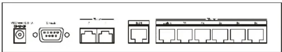
POWER — This socket is an 18 volt, 750mA power input jack. If the power adapter included with the router has been lost or misplaced, please ensure that the replacement adapter meets both the voltage and amperage requirements.
CONSOLE – This 9-pin RS-232 port is used for connecting a console or PC running a terminal emulation program. It provides out-of-band management capabilities for the initial setup and configuration of the router.
PHONE 1 and 2 – These normal telephone jacks can be used to connect telephones or fax machines to the router for use over the ISDN lines. Plug telephone devices into these jacks as you normally would into a telephone wall socket.
ISDN – This socket is used to connect the ISDN line to either an NT-1 or directly to the ISDN wall jack, depending on the type of service delivered by your phone company.
ETHERNET – The six Ethernet ports function as a normal 10 Mbps 10BASE-T Ethernet hub.
?? Uplink - This port is used to connect the router to another hub using a straight-through twisted-pair cable.
?? Ports 1x to 5x – These five ports can be used to connect end-stations to the router using straight-through cables.
Telephone Features
Up to two telephones can be attached to the TW-H6W1IR router via the Phone 1 and Phone 2 telephone jacks located on the rear of the router. The router enables the attached telephones to have a number of features which may or may not be found on normal telephones and are described below. Additional features which must actually be configured are described in the Interface Configuration – ISDN Sub-menu section of this manual.
? ? Hold – This feature is very similar with and can work in conjunction with call waiting as defined in the Interface Configuration – ISDN Sub-menu section of this manual. Press Flash 0 to place someone on hold (Flash is a very brief hanging up of the phone). Press Flash 2 to take the caller off hold.
? ? Hold (and pick up from another location) - Telephones connected to the router can be put on hold by pressing Flash 71, 72, 73, or 74. Press the same number to take the caller off hold and speak from another phone on your telephone network.
? ? Call forwarding – If you wish to forward incoming calls to a different telephone, press *77* and then the phone number you wish to forward the call to. All incoming calls will automatically be
forwarded to the phone number entered. Press #77# to cancel call forwarding.
? ? Three-person conference call – To use this feature, conference calling must be enabled by the telephone company. After this is done, pick up a phone and place a call. After connected, press Flash 0 (refer to call waiting in the Interface Configuration – ISDN Sub-menu section of this manual) and dial the second number. After connected, press flash 3 to speak to both parties at the same time. Press Flash 0 to hang up with the first party called. Press flash 1 to hang up with the second party called.
? ? Call transfer – To transfer a call to the other phone jack on the router: if using Phone 1, press flash 20. If using Phone 2, press flash 10.
Installation and Initial Configuration
This section discusses the different connections that can be made to the router when setting it up.
Initially, you will only wish to connect the console to the router in order to configure the other ports. Once that is complete, you will need to turn off the power to the router and plug in the connection cables to the other devices. Next, power on the other devices. When they have finished powering up, power on the router. Each of these steps is described in detail in the sections below. Please skip any setting adjustments that do not apply to your configuration needs.
For the initial configuration of your TW-H6W1IR, you must use an RS-232 console connection, either to a computer running serial communications software or to a serial data terminal.
After the router has been successfully installed and the initial configuration is complete, you can continue to modify settings through the console, or you can change configuration settings through a remote Telnet connection or through a web browser. See the chapters entitled Configuration and Management and Using Telnet for detailed instructions on using Telnet to configure your TW-H6W1IR.
A Warning on Connection Cables
ISDN and Ethernet cables are very similar to each other. It is important that you use the correct cable for each connection; otherwise, your router could be damaged.
Before connecting or disconnecting an RS-232 cable between two devices, turn both devices off to avoid any chance of damaging them.
Step 1 - Setting up the Console
The initial setup of the TW-H6W1IR, requires connecting a console to the 9-pin RS-232 Diagnostic port on the router's rear panel. A serial cable is supplied with the router in order to make this connection. A console can be a terminal, such as a VT-100, or a normal PC running terminal emulation software (such as Microsoft HyperTerminal, included with Windows). The terminal emulation software needs to be configured to the following parameters:
?? VT100 terminal emulation
?? 9600 baud
?? No parity, 8 data bits, 1 start bit, 1 stop bit
?? No flow control
Step 2 - Connecting the Console to the Router
A serial cable is included in the TW-H6W1IR package. To connect this cable, plug its nine-pin connector into the 9-pin RS-232 Diagnostic port on the router's rear panel, then connect the other end to the serial port on the rear of your computer or data terminal.
Please make sure both machines are turned off before making this connection.
After the connection is made, first power on the console. If you are using a PC, run the terminal emulation software at this time. After the PC and the terminal emulation software are up and running, power on the router.
Using the Console
The Console Program is the interface that you will be using to configure your TW-H6W1IR. Several operations that you should be familiar with before you attempt to modify the configuration of your router are listed below:
? ?Moving the Cursor. Within a menu, use Tab and arrow keys to navigate through different information fields.
? ?Moving Forward to Another Menu. To move forward to a sub-menu below the current one, use Tab or arrow keys to
position the cursor on the sub-menu item and press Enter to view the selected sub-menu.
? ?Entering Information. There are two types of fields that you will need to fill in. The first requires you to type in the appropriate information. The second gives you choices to choose from. In the second case, press the space bar to cycle through the available choices. Upon configuring all fields the sub-menu, position the cursor on SAVE and press Enter to save, or position the cursor on EXIT to cancel.
? ?Refresh Screen. Console screens are notorious for becoming garbled. When this happens, simply press
Step 3 - Connecting an ISDN Line to the Router
Your phone company will provide an S/T interface into your home or office. Plug the ISDN line from the router directly into the ISDN wall socket provided by your phone company.
Step 4 - Connecting a Telephone or Fax Machine to the Router
You can connect a regular telephone, fax machine, or modem to your router to be used for analog calls. Note that the router's other functions all work the same whether you connect an analog device or not.
To connect an analog device, just plug one end of the device's cord into one of the sockets on the back of the router marked PHONE 1 or PHONE 2.
To have incoming calls directed to a device on a PHONE jack, you must enter the telephone number for the phone in the console program under the Interface Configuration, ISDN submenu.
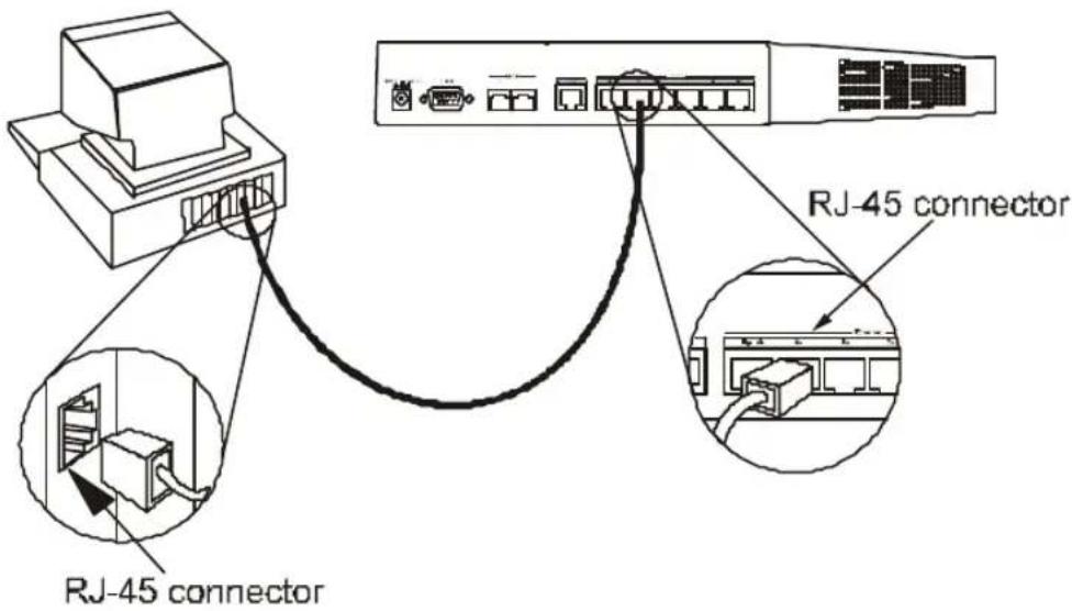
Step 5 - Connecting Ethernet Cables to the Router
Your TW-H6W1IR has six ports for connecting 10BASE-T Ethernet devices to form a LAN. The jacks for ports 1 through 5 are wired to let you connect network end nodes (computers, servers, bridges, other routers, etc.) using standard “straight-through” EIA (Electronic Industries Association) Category 3 or higher twisted-pair cables. The jack for the sixth port is labeled Uplink and is wired to let you connect to another 10Mbps Ethernet or dual-speed hub using a straight-through cable, or an end node using a cross-wired cable.
Please refer to the following chart when deciding on the type of cable necessary for a given connection:
| DEVICE | PORT USED | DEVICE BEING CONNECTED | PORT TYPE | CABLE TO USE |
| NormaRouter | I | Hub orSwitch | Norma I | Crossover (X) |
| Uplink | Straight-Through (||) | |||
| Server (or PC) | Straight-Through (||) | |||
| UplinkServer (or PC) | Hub orSwitch | Norma I | Straight-Through (||) | |
| Uplink | Crossover (X) | |||
| Crossover (X) | ||||
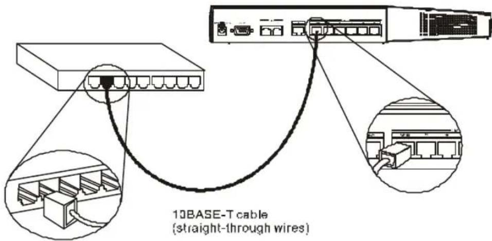
The figure below shows how to make an Ethernet connection between the router and a network end node.
Important Notes on Ethernet Connections
Observe the following rules when connecting devices with twisted-pair Ethernet cables:
? ?For both end-node and uplink connections, use only EIA Category 3 or higher-grade twisted-pair data cables with RJ-45 plugs. In almost all cases, only standard straight-through cables are needed.
? ?Make sure no cable is more than 100 meters (328 feet) long.
? ?When uplinking two hubs together with a straight-through cable, use an uplink-type jack at one end, and an end-node-type jack at the other.
? ?If uplinking more than two hubs together, observe the 5-4-3 rule: no signal, in order to go from one end node to another, must ever pass through more than five twisted-pair cables, four repeaters (that is, hubs), and three uplink cables. This is the maximum signal path in twisted-pair Ethernet. Also be sure never to allow a signal loop to form.
Note that you can connect an end node through the Uplink jack, but to do so you must use a cross-wired cable or cable converter.
Step 6 - Powering Up Devices for Initial Configuration
Plug in the included 18V DC, 750 mA power adapter into the power jack on the router's rear panel.
You should have now connected the RS-232 cable to the console, the ISDN phone line, one or more Ethernet cables, and the power adapter.
At this point in the installation process you can now power up the console computer, run the terminal emulation software (if necessary), and then power up the TW-H6W1IR.
Step 7 - Initial Configuration of the Router
After the console is properly connected and both devices are powered on as described in the preceding sections, you should see the router run through the power on self test (POST). Finally, it will arrive at the logon screen shown below. If the login screen does not appear, press
![TW-H6W1IR Router (Console) User Name [ ] Password [ ] OK Connected 0:02:12 Auto detect 9600 8-N-1 SCROLL CAPS NUM Capture Print echo](/content/2026/06/1189103/images/4c6d1b0d2a1e6a2df00d92ad71355c08e0343d7fb6db3a44c73170bb0358c374.jpg)
To log on to the router, use the factory set username and password 'Admin' (without the quotes). Please note that the user name and password are case-sensitive.
Upon entering the username and password (using the
Step 7 - Configuring the LAN Port
Preparing the router for connection to a LAN only requires enabling the LAN port, enabling IP networking, assigning the LAN port an IP address and enabling telnet (if necessary). After the LAN port is configured, all other features on the router can be configured remotely through the LAN by using the included Windows-based Router Configuration Utility or Telnet. Regardless, the router can always be configured using a console connected to the RS-232 Console port.
To configure the LAN:
- The LAN port must be enabled in the Interface Configuration sub-menu.
? ?Choose Interface Configuration, LAN.
? ?Position the cursor over the State item and press
? ?Position the cursor on the Save option at the bottom of the screen and press
? ?Choose Exit in the sub-menus to return to the Main Menu.
- Enable IP Networking
?? Choose Network Configuration, IP Configuration.
? ? Position the cursor over the last item IP Networking and press
? ? Position the cursor on the Save option at the bottom of the screen and press
- Assign an IP address to the LAN port in the Network Configuration sub-menu of the Main Menu.
? ?Still in Network Configuration, IP Configuration submenu from Step 2 above, choose IP Stack Configuration, LAN.
? ?Enter a valid IP address for the LAN in the first item. You may also enter a Netmask if you wish. For more information about IP
Addresses and Subnet masks, please refer to Appendix B - IP Concepts.
? ?Position the cursor on the Save option at the bottom of the screen and press
? ?Choose Exit in the sub-menus to return to the Main Menu.
- Enable the Telnet/Discovery function on the router.
? ? From the Main Menu choose Advanced Functions.
? ? Choose the Telnet/Discovery Enable option and enable telnet.
? ?Position the cursor on the Save option at the bottom of the screen and press
? ?Choose Exit in the sub-menus to return to the Main Menu.
The router can now be accessed via the LAN by Telnet, the Web-based TW-H6W1IR Router Configuration Utility (included with the router) and other SNMP management applications.
If you have any questions regarding the settings you made or other settings in the submenus, please refer to the next chapter Configuration and Management.
Step 8 – Plugging in All Devices
You can now plug in and power on all other devices connected to the router. Do not power on the router yet.
The router is now able to use the LAN ports.
The router must be further configured in order to get the built-in ISDN modem to function properly, to perform other routing functions, and to manage your IP network. This can now be done by using the console, the included Web-based Configuration Utility or Telnet.
For more information about configuring or managing the router, please refer to the next chapter – Configuration and Management.
Configuration and Management
After the initial startup (POST) test, the router will prompt you for login and password. This is the opening page of the router's out-of-band configuration program, called the Console program. The Console program is stored in the Flash memory chips in the router and the settings are written in EEPROM chips in the router. It is the most basic level for configuring and managing the router and the network to which it is connected.
![TW-H6W1IR Router (Console) User Name [Admin ] Password [ ] OK Connected 0:06:29 Auto detect 9600 8-N-1 SCROLL CAPS NUM Capture Print echo](/content/2026/06/1189103/images/1fca8c085a937dc7d092aee15786370c4dba0a492f83b1263136a503e4864764.jpg)
If you're starting the router for the first time, the default login and password is "Admin" – the login and password are case-sensitive, alphanumeric characters.
Note that once you are in the Main Menu, if there is no activity for more than 5 minutes, the router will automatically log you out. Your first endeavor should be to increase the ‘timeout’ time by adjusting the appropriate value in the System Information sub-menu.
The router can also be configured remotely through a LAN or ISDN connection by using the included Router Configuration Utility or Telnet. However, if you wish to do this, the console program must first be used to initially configure the relevant port on the router. Please see Step 7 - Initial Configuration of the Router on page 21 of this manual for more detailed information.
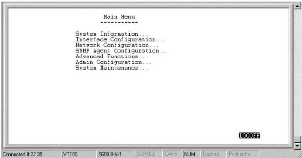
Console Program Main Menu
The Main Menu is shown below.
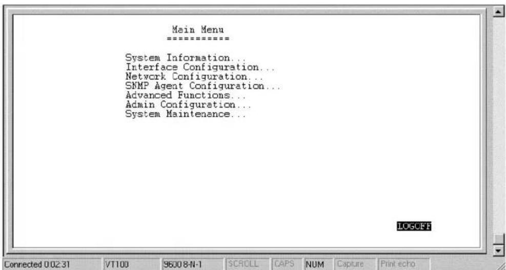
As mentioned earlier, your first endeavor should be to increase the automatic timeout. Enter the System Information to do this. You will see this screen:
System Information
This menu contains administrative and system-related information.
![System Information ==================== System Description ISDN Router System Object ID 1.3.6.1.4.1.604.10.22.3 System Up Time 1 hours 1 minutes 38 seconds System Contact [TRENDnet Technical Support. ] System Name [TRENDnet TW-H6W1IR ] System Location [ ] Console/Telnet Display Timeout in Minutes(0..90) [0 ] System MAC Address 0050BA090301 ISDN Switch Type DSS-1 SAVE EXIT All changes are saved! Connected 0:10:18 VT100 9600 8-N-1 SCROLL CAPS NUM Capture Print echo](/content/2026/06/1189103/images/21ad9cb67a8c8f6dbe66b8ad40c8cea4b90c86a6fbe79b41a9ea19e03f23a315.jpg)
The above parameters are described as follows:
?? System Description – this is a non-changeable, short description of the product.
?? System Object ID – this is the enterprise-specific MIB Object ID indicating this type of router.
?? System Up Time – shows how long the router has been running since the last power off or reset.
?? System Contact – enter the name of the department or individual responsible for maintaining the router.
?? System Name – give the router a descriptive name for identification purposes.
?? System Location – enter the geographic location of the router.
?? Console/Telnet Display Timeout in Minutes – this is a security measure to automatically logoff from the console menu after a given idle time. Enter a timeout time between 0 and 90 minutes. Zero specifies no timeout.
?? System MAC Address – the physical address of this router.
?? ISDN Switch Type – the type of ISDN switch used by the telephone company that the TW-H6W1IR can communicate with. The TW-H6W1IR currently supports only the DSS1 switch type.
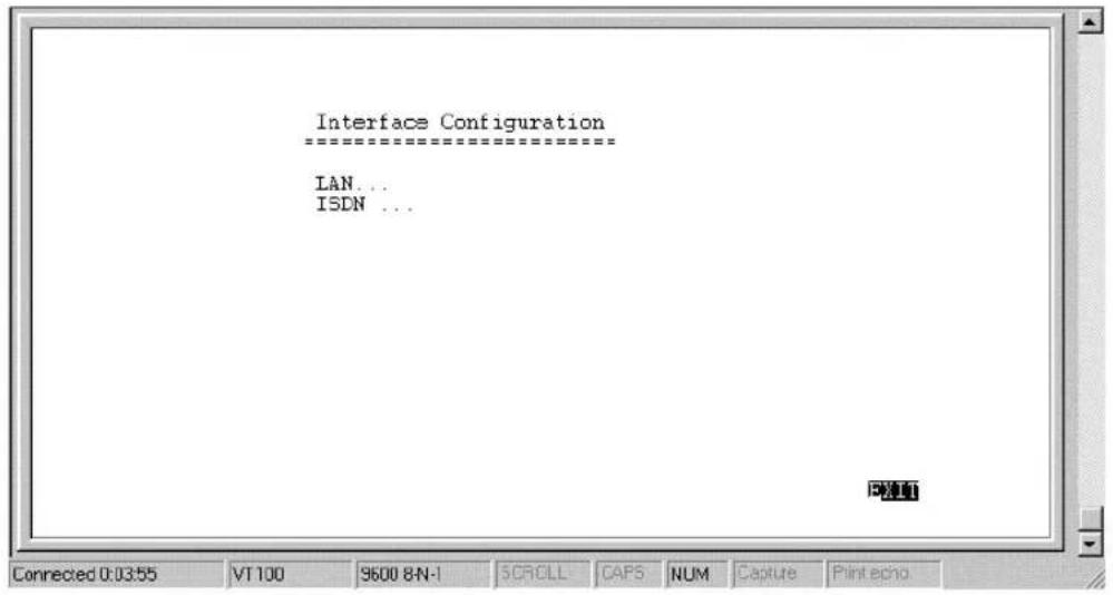
Interface Configuration
Under Interface Configuration in the main menu is the following interface configuration screen, used to configure the LAN and ISDN interfaces:
LAN Sub-menu
![LAN ===== Description [Branch Office ] Operation Mode 10TX HD State SAVE EXIT Connected 0:04:15 VT100 9600 8N-1 SCROLL CAPS NUM Capture Print echo](/content/2026/06/1189103/images/0e130d2844b7e3970b8139550c54dd5455ff89cde7e17dc4f4fa9df24e597296.jpg)
The parameters are described below:
?? Description – this is a user-defined, 32-character identifier used to name the LAN.
?? Operation Mode – The LAN port is 10BASE-T only.
?? State – this is a toggle, to disable or enable the LAN interface.
ISDN Sub-menu
![ISDN ===== Description [Branch Office ISDN ] Switch Type DSS-1 B1 Channel Usage Country ID [5 ] ISDN Data [ ] A/B Adapter 1 [ ] A/B Adapter 2 [ ] Phone 1 Call Waiting Phone 2 Call Waiting POTS Lines Global Reception Block Outgoing CLID Auth Type Call Bumping State E2 Channel Usage SAVE EXIT Connected 0:05:11 VT100 96008-N-1 SCROLL CAPS NUM Capture Print echo](/content/2026/06/1189103/images/1a12ee5c5b3842a4ed3567ad7cf3077e7814b0a1e19974050838f7b703019496.jpg)
The parameters are described below:
?? Description – this is a user-defined, 32-character identifier used to name the ISDN.
?? Switch Type – this parameter defines the type of ISDN service used. Currently, the TW-H6W1IR only supports DSS-1 type ISDN lines.
?? B1 and B2 Channel Usage – this defines whether the ISDN line is a leased line or a normal switched line. If you are not using a leased line connection, set this item to Switch.
?? Country ID – this field needs to contain the country parameter. Without this information, the router cannot establish a connection. A list of country ID numbers is located in Appendix E – Country ID Numbers.
?? ISDN Data – this field must contain the incoming telephone number for data calls. In other words, it is your ISDN line’s data phone number.
?? A/B Adapter 1 and 2 – enter the telephone numbers for your voice/analog lines.
?? Phone 1 and 2 Call Waiting – If you have applied for and received call waiting capabilities for your ISDN voice lines, you must enable these settings in order for the call waiting feature to function.
There are 4 special operations for using call waiting (flash means a very brief hanging up of the phone. In other words, for the first option below, flash 0, click the hang up button on your phone very quickly and then press the number 0 on your telephone's keypad):
Flash 0 - disconnect the first phone call established.
Flash 1 - disconnect the second phone call established.
Flash 2 - switch between the two phone calls.
Flash 3 – speak to both parties simultaneously (if conference calling is enabled by your phone company).
?? POTS Lines – [Plain Old Telephone Service]. Enables or disables phone calls on the Phone 1 and Phone 2 jacks on the rear of the router.
?? Global Reception – When this is enabled, the Phone 1 and Phone 2 jacks will receive all phone calls directed to them by the telephone company's switch. When disabled, the router will check incoming calls to the Phone 1 and 2 jacks against the telephone numbers specified in the A/B Adapter 1 and 2 fields above.
?? Block Outgoing CLID – When this is enabled, your ISDN data phone number and voice phone numbers will never be sent out when trying to establish a connection. Thus, even if sites being called have Caller ID, they still won’t be able to know your phone number.
?? Auth[entication] Type – this defines the authorization protocol that will be used when accepting a dial-in connection. The choices are Password Authentication Protocol [PAP], Challenge Handshake Authentication Protocol [CHAP] or None. PAP and CHAP do not provide a screen for users to manually enter their Username and Password – instead, this data must be entered into the dialing software before placing the call. Make sure the device dialing in is using the same protocol as defined here. The None setting may be used when you do not wish dial-in users or networks to identify themselves or be subject to security.
?? Call Bumping – This setting only takes effect when both B channels are connected and using multi-link PPP. If this is the case and call bumping is enabled, when you receive and incoming voice call, the second B channel will be dropped (with all traffic being moved to the first B channel) and the voice call will be received. If disabled, both B channels will continue their data transmissions uninterrupted and the voice call will be ignored.
?? State –enables/disables the ISDN port.
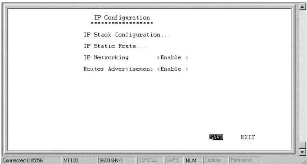
Network Configuration
IP protocol configuration and static routes are configured in the Network Configuration sub-menu. This menu is shown below:
IP Stack Configuration
The network interface IP address, mask and protocols are specified in the IP Stack Configuration submenus. Below, the submenus for both the LAN and ISDN interfaces are shown.
![IAN --------> IP Address [10.2.77.80 ] Netmask [255.0.0.0 ] Forwarding Routing Protocol Routing Mode IF Multicasting Multicast Protocol ICMP Version DHCP Client SAVE EXIT Connected 0:06:21 VT 100 9600 8N-1 SCROLL CAFS NUM Capture Print echo](/content/2026/06/1189103/images/e1a3e01d58ad0f4a270789535d20f87f55d3433eec7d409b8fb88cb08a49a66e.jpg)
![ISDN Link 1 ==================== IP Address [20.20.20.1 ] Netmask [255.0.0.0 ] State Routing Protocol Routing Mode IF Multicasting Multicast Protocol ICMP Version RIP Spoofing SAVE EXIT Connected 0:06:41 VT100 9600 8N-1 5CROLL CAFS NUM Capture Print echo](/content/2026/06/1189103/images/b6c1a10fca77281ab2f80123d94f7c39557836954762b8af8f7b7fc23b3cfee1.jpg)
The parameters are described below:
?? IP Address – this is the IP address for the router on the network to which this interface is connected.
?? Netmask – this is a 32-bit bit mask that shows how the IP address is to be divided into network, subnet and host parts. The netmask
has ones in the bit positions in the 32-bit address which are to be used for the network and subnet parts, and zeros for the host part. The mask should contain at least the standard network portion (as determined by the address's class), and the subnet field should be contiguous with the network portion.
?? Forwarding (LAN) – this enables or disables communications between this router and other router(s) on the LAN.
?? State (ISDN) – this is a link method between this interface and adjacent router(s). The methods are described:
- AUTO – this obtains and utilizes the IP address assignment from your ISP (Internet Service Provider).
- DISABLE – this disables this interface.
- IP STACK - this enables this interface, and the IP address used will be the value of the parameter, IP Address.
- UNNUMBER – this utilizes a method of connecting this router with adjacent routers, without having to define an IP network prefix between them. The adjacent routers must have UNNUMBER capability too.
?? Routing Protocol – this is a distance vector routing protocol. RIP is an Internet standard Interior Gateway Protocol defined in RFC 1058 and RFC 1723. Routing information is sent periodically (each 30 seconds, or triggered by topology change) to an adjacent router. The adjacent router must be using the same protocol. Setting this to RIPv1&V2 will give the router the ability to make routing information exchanges with any adjacent router.
?? Routing Mode – this parameter allows the router to specify the extent to which it partakes in the RIP on this port. The options are described below:
- None – the router will not participate in any RIP exchange with adjacent routers.
- Listen – the router will incorporate routing information from adjacent routers, but will not send its own routing table.
- Talk – the router will send adjacent routers its own routing table, but will not incorporate routing information from them.
- Both – the router will incorporate routing information from adjacent routers, and will send adjacent routers it's own routing table.
?? IP Multicasting – this feature enables or disables the router’s ability to route IP Multicast packets from one interface to another (for example, from the LAN ports to the ISDN port). IP Multicasting is a bandwidth-saving method for transmitting data to more than one host. IP Multicasting is often used when sending/receiving audio or video data. When IP Multicasting is enabled, the router will search its multicast forwarding table and depending on the result of the search will either forward the packet or add the group to the table.. If IP Multicasting is disabled, all multicast packets received by the router will be dropped, effectively limiting multicasting to the LAN. The router can also perform DVMRP if this feature is enabled (see Multicast Protocol below), which allows the TW-H6W1IR to share multicast information with other routers, enabling IP multicasting over the ISDN port.
?? Multicast Protocol – if this parameter is set to None, the router will only use the Internet Group Management Protocol (IGMP), if IP Multicasting is enabled above. This effectively limits multicast data to the local network. If set to DVMRP (Distance Vector Multicast Routing Protocol), the router will also use this protocol to share its multicast information with other routers (much like RIP), in effect, enabling multicasting on the WAN (ISDN) port.
?? IGMP Version – configures the router to use either IGMP version 1 or 2. A major difference between the two is that version 2 allows the router to communicate multicast information with other routers (via the ISDN port), even if the other router isn’t using DVMRP.
?? DHCP Client (LAN) – this feature allows the LAN port to be assigned an IP address from a DHCP server other than the one in the router. This feature should be enabled only for special configurations (such as the presence of a cable modem on the LAN) where you wish the router to work with a device on the network that must act as a DHCP server. Otherwise, this feature should be kept disabled.
?? RIP Spoofing (ISDN) – this feature should only be enabled if you have more than one router on your network and this router is providing your WAN connection. In this case, if the WAN connection is dropped due to inactivity and this feature is enabled, RIP packets will be sent to the other routers on the network telling them that data can still be sent to the WAN via this router. Otherwise, the other routers will learn that the WAN link has been disconnected and will no longer forward packets destined for the WAN to this router, causing the packets to be dropped before Bandwidth on Demand has a chance to reestablish the WAN connection.
IP Static Route
A static route is a permanent entry in the routing table. Static routing provides a means of explicitly defining the next hop router for a particular destination network IP address. Each static route entry also allows for a metric (a.k.a. hop count) to be specified.
![IP Static Route IP Address Netmask Gateway Hops Intf State 1. [0.0.0.0] [0.0.0.0] [172.22.3.1] [1] 2. [202.12.125.0] [255.255.255.0] [210.172.23.1] [1] 3. [202.12.124.0] [255.255.255.0] [202.12.129.1] [1] 4. [0.0.0.0] [0.0.0.0] [0.0.0.0] [0] 5. [0.0.0.0] [0.0.0.0] [0.0.0.0] [0] 6. [0.0.0.0] [0.0.0.0] [0.0.0.0] [0] 7. [0.0.0.0] [0.0.0.0] [0.0.0.0] [0] 8. [0.0.0.0] [0.0.0.0] [0.0.0.0] [0] 9. [0.0.0.0] [0.0.0.0] [0.0.0.0] [0] 10. [0.0.0.0] [0.0.0.0] [0.0.0.0] [0] 11. [0.0.0.0] [0.0.0.0] [0.0.0.0] [0] 12. [0.0.0.0] [0.0.0.0] [0.0.0.0] [0]](/content/2026/06/1189103/images/4cb67bfd45d1dd565fd4d998cc538f2fce67965c794a2c4af3e80b7cdc669ac4.jpg)
The parameters are described below:
?? IP Address – this specifies the destination network IP address (or a host, depending on the netmask) and pairs it with a gateway.
?? Netmask – this mask shows how the destination IP address is to be divided into network, subnet and host parts. The netmask has ones in the bit positions in the 32-bit address which are to be used for the network and subnet parts, and zeros for the host part.
?? Gateway – this is the adjacent next hop router, for which the packets, arriving to this router with this destination IP address, will be forwarded.
?? Hops - this is an associated RIP metric that may have its value set between 1 and 15, inclusive. A metric value higher than 15 (such as 16) means that the network is unreachable.
?? Intf [Interface] – this is the network interface containing the gateway that the packets will be forwarded through.
?? State – this enables/disables a particular entry.
IP Static Route Examples
The IP Static Route Table shown in the example IP Static Route screen above has the first three entries configured for common implementations of static routing.
The first entry assumes that ISDN1 has a connection to the Internet and defines the default next hop router. If you use this router to connect to the Internet it is very important that you create an entry here that defines the default next hop router as your ISP. This configuration is also commonly used when RIP exchanges with other Internet routers (on ISDN1) are disabled.
The second entry shows how to configure static routes when there is another router on the LAN. The IP Address shown (202.12.125.0) is the network address for a branch office, for example. The Gateway Address (210.172.23.1) is the IP address to the LAN port on another router on the LAN that maintains an ISDN connection to the branch office.
The third entry is an example of an enterprise ISDN connection (through telephone lines) to another router, at a branch office for example. The IP Address is the network address of the branch office. The Gateway Address is the IP Address of the ISDN port on the
branch office router. This configuration assumes there is a modem on ISDN2 maintaining a dial-up connection to the branch office.
IP Networking
Under the IP Configuration sub-menu, the IP Networking function can toggle to connect/disconnect this router from the entire IP network.
When IP Networking is disabled, all routing functions are stopped. The only IP Address the router will act on is its own, via Telnet for example.
Router Advertisement
When this option is enabled, the router will periodically send out ICMP packets that announce itself on the network. These ICMP packets are utilized by the Windows 98 or later operating system, which will automatically update the default gateway setting on the computer in which it is installed.
SNMP Agent Configuration
The Simple Network Management Protocol (SNMP), defined in STD 15, RFC 1157, is a protocol governing the management and the monitoring of IP network devices and their functions. The TW-H6W1IR supports the use of SNMP to acknowledge communication between management stations and itself. Basically, the TW-H6W1IR, when connected to the network, acts as an SNMP agent, a software process that responds to queries using SNMP to provide status and statistics about the router.
Following is a description of how to configure the TW-H6W1IR for SNMP management.
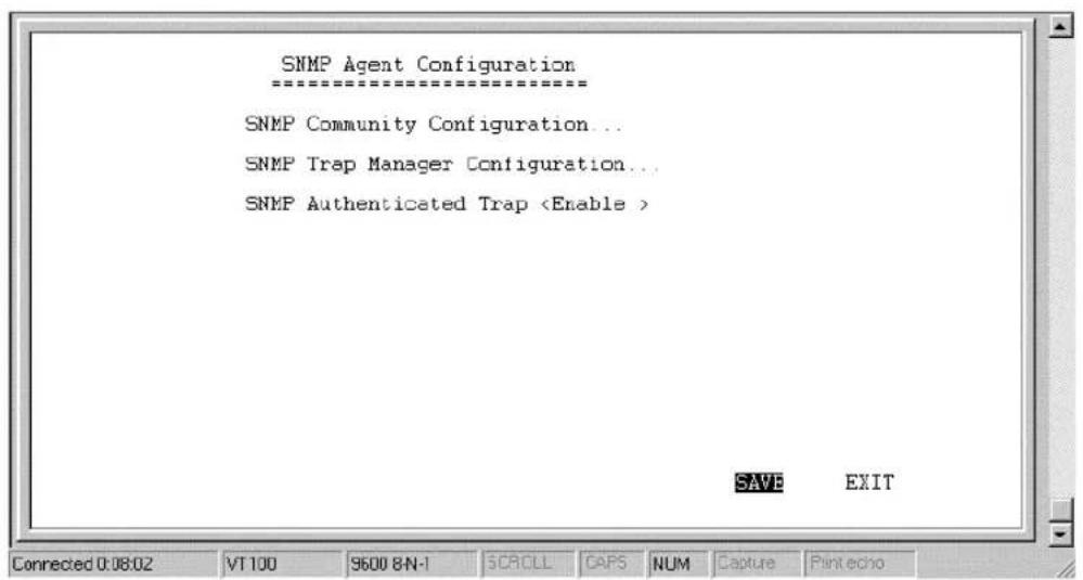
From the main menu, select SNMP Agent Configuration. This will bring you to the SNMP Agent Configuration Menu, shown above.
SNMP Community Configuration
Select and Enter the SNMP Community Configuration sub-menu. You will see the following configuration screen:
![SNMP Community Configuration ==================== SNMP Community String Access Right Status [public] [private] [ ] [ ] SAVE EXIT Connected 0:08:54 VT100 9600 8N-1 SCROLL CAPS NUM Capture Print echo](/content/2026/06/1189103/images/7d6753c949082b7d6c5ff2f235bb5175727a05e4b056e2f52ec90db6fdce08c1.jpg)
The parameters are described below:
?? SNMP Community String – this community string is a user-defined identifying name used to group together some arbitrary set of SNMP application entities managed by the network manager.
?? Access Right – this element of the set {READ ONLY, READ/WRITE} is called the SNMP access mode. If the SNMP Community String has an Access Right of READ/WRITE, then that Community String is available as an operand for the get, set, and trap operations. Otherwise, if the Community String's corresponding Access Right is READ ONLY, then it is available as an operand for the get and trap operations only.
?? Status – this validates or invalidates the use SNMP Community String, by setting the string to 'Valid' or 'Invalid'. Note that setting
the use of the string to ‘Invalid’ is the same as removing the string, however, the string remains so as to be validated at an appropriate time.
SNMP Trap Manager
From the SNMP Agent Configuration menu, select and enter the SNMP Trap Manager sub-menu. You will see the following configuration screen:
![SNMP Trap Manager IP Address SNMP Community String(State [0.0.0.0] [ ] [0.0.0.0] [ ] [0.0.0.0] [ ] [0.0.0.0] [ ] [0.0.0.0] [ ] SAVE BND1 Connected 0:09:30 VT 100 9600 8-N-1 SCROLL CAFS NUM Capture Print echo](/content/2026/06/1189103/images/8779f82500d87d0eeca67e113f082a358deca92957b3226e5fd82127f05491e1.jpg)
The parameters are described below:
?? IP Address – enter the IP address of the host who will act as an SNMP Management Station. The TW-H6W1IR router will send SNMP traps to these addresses.
?? SNMP Community String – the community string is a user-defined identifying name used to group together some arbitrary set of SNMP application entities managed by the network manager. Traps will be sent to the IP Address (previous parameter) as long
as the corresponding Community String, in the Management Station's trap manager software, is the same.
?? State – this validates or invalidates the use of the SNMP Community String, by setting the use of the string to Valid or Invalid. Note that setting the string to Invalid is the same as removing the string, however, the string remains so as to be validated again at an appropriate time.
SNMP Authenticated Trap
Returning to the SNMP Agent Configuration menu, you can 'Enable' or 'Disable' an authentication failure trap message being sent to the Management Station by the router. When an SNMP packet with an invalid community name is received, it will be dropped. If this parameter is enabled, a trap will be sent to the network manager; if this parameter is disabled, no trap will be sent.
Advanced Functions
The Advanced Functions menu contains most of the more complex configuration settings and is shown below:
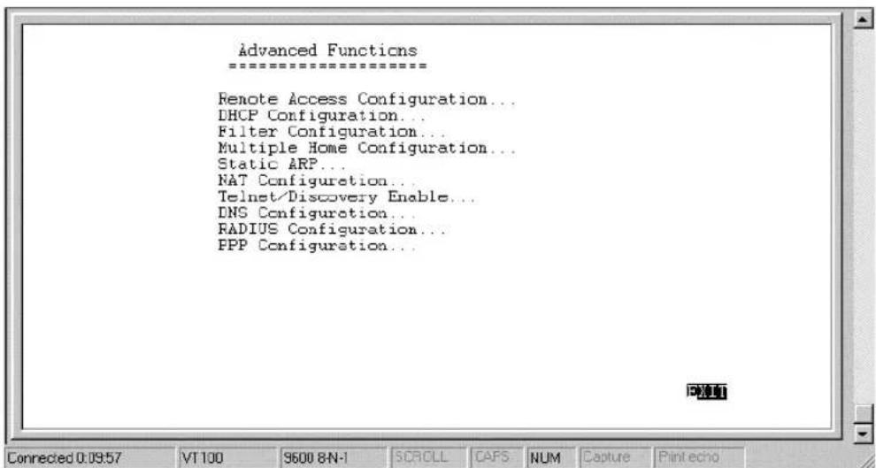
Remote Access Configuration
The Remote Access Configuration menu is used to set up the router for dial-in and dial-out connections over the ISDN line. An ISDN line has a D channel for establishing connections and two B (Bearer) channels, which transmit and receive the actual signals, whether voice or data. The two B channels can support two independent remote connections or be banded together using Multi-link PPP to implement Bandwidth on Demand (configured separately in the PPP Configuration menu, the last item in the Advanced Functions window).
The B-Channels can also carry voice and fax calls, which are routed to the telephone jacks located on the rear of the router. Please note,
however, that the TW-H6W1IR can maintain only two connections at a time via the two B channels, whether the connections are voice, data, dial-in users, remote networks or a combination thereof.
Remote Operation Overview
The TW-H6W1IR is very flexible and can be configured for a variety of remote connections. Since configuring the router can be quite complex - depending on the number and type of remote connection(s) you wish to implement – we have described some of the basic functions and procedures below.
Dial-In User Connections
Dial-in users are defined as a single user on a computer, such as a person working at home, who dials into the office to use network resources. In almost all cases, a Dial-In User Profile needs to be set up for each user who will dial in to the router so the router can tailor the connection for each user. Once this is done, the remote user will be able to use network resources as if he were connected locally. When the user dials into the TW-H6W1IR, the call comes into the D-channel and after answering the phone, the TW-H6W1IR:
-
Identifies the Username and Password using the authentication protocol defined in the Interface Configuration, ISDN submenu. The dial-in user is not prompted for this information, but must enter it into his dialing software before dialing.
-
Checks the Username and Password against those defined in the Dial-In User Profiles and Remote Network Profiles.
-
Assuming a matching Dial-In User Profile is found, the router may configure the IP address of the remote station (as defined in the Dial-In User Profile).
- Configures a dial-in Interface (a virtual circuit) to handle the connection.
- Establishes the connection on whichever B-channel (physical port) is open by mapping the dial-in interface to that port.
- In the case where the Dial-In User does not need to supply a Username and Password (Auth Type is set to None in the Interface Configuration submenu) the remote computer must have its own IP address.
Remote Network Connections
Remote networks are defined as other networks (LANs) that have WAN connections using a router, Internet server, network modem or similar device (in this document however, we will assume the remote device is a router). In almost all cases, a Remote Network Profile needs to be set up for each network that will connect to the TW-H6W1IR via the ISDN lines. The Remote Network Profiles are necessary for the router to identify and tailor the connection to the remote network's router. Once this is done, a connection between the two routers can be made and computers on each network can communicate with each other.
Dial-In Network Connections
A dial-in network connection is very similar to a dial-in user connection. When the remote router dials into the TW-H6W1IR, the call comes into the D-channel and after answering the phone, the TW-H6W1IR:
- Identifies the Username and Password using the authentication protocol defined in the Interface Configuration, ISDN submenu.
-
Checks the Username and Password against those defined in the Dial-In User Profiles and Remote Network Profiles.
-
Assuming a matching Remote Network Profile is found, the router may configure the IP address of the remote station (as defined in the Remote Network Profile).
- Configures the specified ISDN Interface (a virtual circuit) using the configuration parameters defined in the Interface Configuration menu and the Remote Network Profile to handle the connection.
- Establishes the connection on whichever B-channel (physical port) is open by mapping the dial-in interface to that port.
Dial-Out Network Connections
Dial-out network connections are much different than dial-in connections.
When a packet on the LAN reaches the router, the TW-H6W1IR will:
- Check its routing table to try to identify where this packet should go. It looks for two variables in the routing table, Gateway address and Interface. There are four possible results:
I. In the case where the destination resides in the same IP network on the LAN, the routing engine never acts on the packet and it is sent directly to the destination through the built-in hub.
II. In the case where the destination resides on a different IP network on the LAN (which can happen when Multiple Home Configuration is set up), the router will send out an ARP request to obtain the MAC address of the destination computer (or router) and deliver the packet. Note that defining Static ARPs can speed up delivery since the router won't need to send out an ARP request.
III. In the case where the router finds a match in the routing table (which includes IP Static Routes), it uses the Gateway address and Interface numbers to identify the correct Remote Network Profile to use to dial out. From the Remote Network Profile, the router gets the telephone number and other information and dials out, establishes a connection and delivers the packet. If you have a connection to the Internet, it is very important that you define the default next hop router in the IP Static Routes submenu of the console program as your ISP (see the IP Static Routes section of this manual for more detailed configuration
information). This is because if a user on your LAN makes a request to download a web page for the first time, for instance, since it is the first time, the TW-H6W1IR will not have any record of the web page's IP address. If no default next hop router is defined, the request will be dropped and the user will get a 'Destination Unreachable' error message. However, if a default next hop router is defined in the IP Static Routes, the TW-H6W1IR will pass this request on to the ISP (the request will go through) and the user will receive the web page.
IV. In the case where there is no match for the destination IP address in the routing table, and no default next hop router is defined, the packet will be dropped and no action will be taken.
The Remote Access Configuration submenu is shown below. All items in the submenu are described as follows.
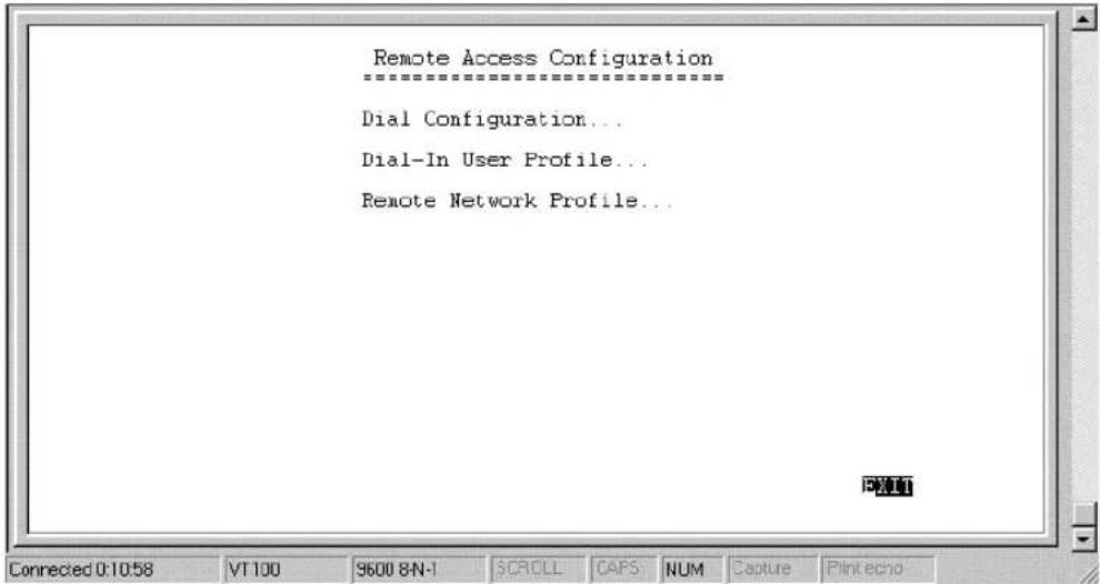
Dial Configuration
You can configure the two ISDN interfaces on your TW-H6W1IR to dial-out only when a packet is forwarded to that interface, and hang up after all data has been transferred and the link is idle. This can be used to lower the cost of an unpopular link or used as a backup link to your
ISP. This feature is commonly called “Dial on Demand”. ISDN interfaces can also be configured here to receive calls from dial in users and other networks, called “Remote Access”. Please note however, that in all cases, after configuring the ISDN Links in the Dial Configuration submenu, they must be further configured in the Dial-In User Profile submenu or Remote Network Profile submenu.
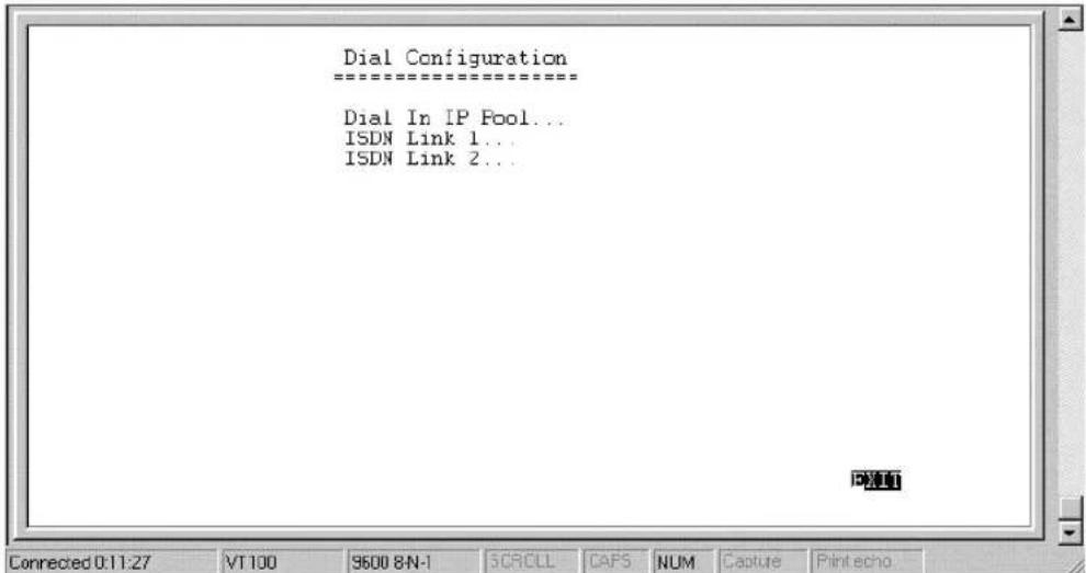
Dial In IP Pool
The dial in IP pool allows you to define a range of IP addresses that will be reserved for and assigned to dial-in users.
![Dial In IP Pool =================== IP Address [170.100.200.1 ] Range [2 ] SAVE EXIT Connected 0:12:21 VT 100 9600 8N-1 SCROLL CAPS NUM Capture Print echo](/content/2026/06/1189103/images/7362d1490963711aac107b5511f846d9fa3b619f618f482b42a899b05f7a5766.jpg)
The items are described as follows:
? ? IP Address – is the first IP Address that will be assigned to a dial-in user.
? ? Range – is the number of IP Addresses that can be assigned. In the window shown above, dial-in users will be assigned the IP Addresses 170.100.200.1 or 170.100.200.2 (only two are necessary since the router used in the examples has only two ISDN ports).
ISDN Link 1
This submenu contains a number of settings (shown below) which allow you to configure the router to dial out.
![Idle Time [30 ] Diel-Out Retry Time [5 ] Diel-Out Retry Count [3 ] Diel on Demand Set Peer IP as Default Gateway SAVE EXIT Connected 0:36:09 VT100 9600 8N-1 SCROLL CAPS NUM Capture Print echo](/content/2026/06/1189103/images/8f362e2f97b2587570c024d2b40effe320c49dffbe0d8f07ed2e7edca28dd62e.jpg)
The parameters are described below:
?? Idle Time – this is the elapsed time (in seconds), of inactivity, that will trigger the router to disconnect this interface.
?? Dial-Out Retry Time – this is the time (in seconds) the router will wait before the next dial attempt.
?? Dial-Out Retry Count – this is the specified maximum number of dial attempts the router will make when trying to establish a connection on this interface.
?? Dial on Demand – this disables or enables dial on demand on this interface. If enabled, when a packet arrives at this port, the router will search for a Remote Network Profile that further configures this ISDN port for dialing-out.
?? Set Peer IP as Default Gateway – when enabled, this feature sets the IP address of the remote device as the default gateway (default next hop router) for all packets not found in the routing table. This option should be enabled for the ISDN circuit (ISDN1
or ISDN2) that is used to connect to the Internet. Also, if the Peer IP is set as the default gateway here, you still need to define a static default route in the Network Configuration, IP Static Route submenu, but you don't need to designate a gateway IP address for the static route (the routers will automatically negotiate and adjust the gateway IP setting accordingly). And also make sure that the Remote IP Address in the Remote Networks Profile is set to 0.0.0.0. Note that only one ISDN circuit should be connected to the Internet, and only one ISDN circuit (the same one) should be the default gateway.
Dial-In User Profile
The Dial-In User Profile is used to configure the TW-H6W1IR for single users (for example a person working at home) to dial in to the router and gain access to the network. At least one User Profile must be configured for each user who will dial in (in conjunction with Dial Configuration settings). Please note that WAN connections to computers on other networks must be defined in the Remote Network Profile submenu.
Up to eight users can be set up to dial in to the router. However, more dial-in users can be accommodated by using a Radius server as described in the Radius Configuration section of this manual. Please note that when a Radius server is being used, the Dial-in User Profiles will be disabled.
The Dial-In User Profile submenu appears below:
![Name [Charlie ] Password [ ] Ren CLID [5550069 ] Default IP [10.201.22.5 ] IP Address Supply State SAVE EXIT Connected 0:07:56 VT100 9600 8N-1 SCROLL CAPS NUM Capture Print echo](/content/2026/06/1189103/images/d33e70647b5cee683c29f4f84e1d2024fdd1a12ea82e4c2662e574515f29f7a6.jpg)
The parameters in the above window are described as follows:
?? Name – the maximum length is 64 characters. This username is for password challenges (authentication). The user dialing in must supply this username in order to be allowed access to the router.
?? Password – this is the password associated with the above Name field.
?? Rem CLID – Remote Caller ID. This is the telephone number of the Remote User and is used for security. When a phone number is entered in this field, the router will make sure that the incoming call is coming from the same phone number as the one defined here. In other words, the remote user can only be calling from the telephone number defined here, otherwise the call will not be accepted. This function is disabled if the field is left blank.
?? Default IP – this is the IP address that will be assigned to the dial-in user when the IP Address Supply setting below is set to Default.
Assigning an IP address to the remote computer ensures that the IP address does not clash with other IP addresses on your network.
?? IP Address Supply – this field defines how the remote user will obtain an IP address. The choices include:
Default – uses the Default IP address defined above,
Dynamic - taken from the Dial In IP pool, or
None - the remote user supplies his own IP Address.
?? State – enables/disables this User Profile.
Remote Network Profile
The Remote Network Profile is used to configure the router for ISDN connections to other networks. In practice, the TW-H6W1IR will either dial-out to or receive incoming calls from another router, the 'gateway' to the other network.
![Remote Name [Branch 2 ] Direction Interface Incoming : Name [Branch 2 ] Password [ ] Rem CLID [5556969 ] Outgoing : Name [Branch 2 ] Password [ ] Phone Number [5556969 ] Remote IP Address [10.23.66.1 ] IP Address Supply State Connected 0:06:43 VT100 9600 8N-1 SCROLL CAFS NUM Capture Print echo SAVE EXIT](/content/2026/06/1189103/images/3867a0563aab1a32f664af70de8cbdbb732c95a21e03481e719e334f0680ad29.jpg)
?? Remote Name – Name for the remote network that the TW-H6W1IR is being set up to connect with.
?? Direction – dial-[In], dial-[Out], or [Both]. This field defines whether the router on the other network will dial-[In] to the TW-H6W1IR to establish a connection, the TW-H6W1IR will dial-[Out] to the other network, or a connection can be established [Both] ways.
When this is set to In, the TW-H6W1IR will only establish a connection with the other network by receiving calls on the ISDN port specified in the Interface field below. Also, the incoming calls will be subject to the Name, Password and Rem CLID fields in the Incoming section below.
When this is set to Out, the router will only make calls on the ISDN interface specified in the Interface field below. Also, the outgoing calls will be subject to the Name, Password and Phone Number fields in the Outgoing section below.
When set to Both, the dial in and dial out conditions described above will both be observed.
?? Interface – ISDN Link 1 [ISDN L1] or ISDN Link 2 [ISDN L2]. This field is used to assign a remote network to a logical (virtual) interface called a virtual circuit. More than one remote network can be configured to use the same interface, but they cannot be connected at the same time. Thus, if you wish to have two WAN connections operate simultaneously, make sure they are configured on different interfaces. On the other hand, if you have two dial-out remote network profiles but wish to keep one line always open for dial-in users, make sure the two dial-out profiles use the same interface. In this case, the two profiles will share the same interface;
the second one using it after the first one's idle time has expired and it has relinquished it.
?? Incoming
?? Name – the maximum length is 64 characters. This username is for password challenges (authentication). The user dialing in must supply this username in order to be allowed access to the router.
?? Password – this is the password associated with the above Name field.
?? Rem CLID – Remote Caller ID. This is the telephone number of the Remote User and is used for security. When a phone number is entered in this field, the router will make sure that the incoming call is coming from the same phone number as the one defined here. In other words, the remote user can only be calling from the telephone number defined here, otherwise the call will not be accepted. This function is disabled if the field is left blank.
??Outgoing
?? Name – the maximum length is 64 characters. Spaces and punctuation are not usually accepted. This username is for password challenges (authentication) which are automatically handled by the router when dialing out. The TW-H6W1IR will use PAP and CHAP (whichever works) to make the connection.
?? Password – this is the password associated with the above Name field.
?? Phone Number – this is the telephone number that will be dialed to make the outgoing connection.
?? Remote IP Address – this is the IP address that will be assigned to the dial-in network when the IP Address Supply setting below is set to Default. Assigning an IP address to the router dialing in ensures that the IP address does not clash with other IP addresses on your network. For dial out connections utilizing dial on demand, the IP address of the remote router needs to be entered here so the router knows which remote network to establish a connection with to deliver the packet.
?? IP Address Supply – this field defines how the router will assign an IP address to a device dialing in. The choices include:
Default - uses the Remote IP address defined above,
Dynamic - taken from the Dial In IP pool, or
None - the remote user supplies his own IP Address.
?? State – enables/disables this Remote Network Profile
DHCP Configuration
The TW-H6W1IR Router implements the Dynamic Host Configuration Protocol (DHCP), which allows the entire IP network to be centrally managed by the router. It does this by assigning IP addresses and configuration parameters to hosts as they are powered on and come onto the network. This can be a great help for network administration since many administrative tasks such as keeping track of each computer's IP address are handled by the router. The TW-H6W1IR can implement DHCP in one of the two ways shown below:
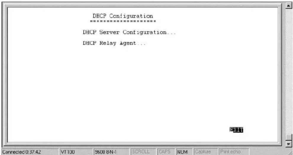
DHCP Server Configuration
When acting as a DHCP server, the TW-H6W1IR will manage many of the IP network parameters. The TW-H6W1IR will never assign a broadcast or network IP addresses to hosts, even if such an address is included in the specified range.
Dynamic IP Pool
The dynamic IP pool screen shown below contains the parameters that the router can set on the hosts. Please note that the Dynamic IP Pool cannot be enabled when the DHCP Agent feature is enabled.
![Dynamic IP Pool IP Address [202.93.47.1 ] Range [100 ] Netmask [255.255.255.0 ] Gateway [202.93.47.254 ] Lease Time [72 ] DNS IP [140.113.1.1 ] WINS IP [0.0.0.0 ] Domain Name [ALL ] &state BAVE EXIT Connected 3:40:31 VT100 9600 8-N-1 CDROLL CAPE NUM Copina FINANCER](/content/2026/06/1189103/images/ea192c546ae7e158bc1eb653a481d3ae674ee15c6a257084d44a400c52c6c8ef.jpg)
The parameters are described below:
?? IP Address – this is the base (starting) address for the IP pool of IP addresses to be assigned.
?? Range – this is the range of contiguous, IP addresses, above the base IP Address above. In the above example, the IP addresses assigned host computers as they come onto the network would be 202.93.47.1, 202.93.47.2 ... 202.93.47.100.
?? Netmask – this mask informs the client, how the destination IP address is to be divided into network, subnet and host parts. The netmask has ones in the bit positions in the 32-bit address which
are to be used for the network and subnet parts, and zeros for the host part.
?? Gateway – this specifies the Gateway IP Address that will be assigned to and used by the DHCP clients.
?? Lease Time – this specifies the number of hours a client can lease an IP address, from the dynamically allocated IP pool. The maximum value is 65535 and a value of 0 means the lease is permanent.
?? DNS IP – this specifies the Domain Name System server, used by the DHCP clients using leased IP addresses, to translate hostnames into IP addresses or vice-versa.
?? WINS IP – this specifies the IP address of the Windows Internet Naming Service server. This server has software that resolves NetBIOS names to IP addresses.
?? Domain Name – this is the common suffix, shared by networked hosts, used to represent a common network domain.
?? State - this enables/disables the dynamic IP Pool function.
Static IP Pool
The Static IP Pool configuration functions in much the same way as the Dynamic IP Pool configuration. The only difference is that a particular IP address can be assigned to a particular host. This is used for hosts such as servers that need to have static IP addresses to function properly or to make them accessible to remote users. The host is identified by the MAC address of its NIC, which must be entered on this screen.
![IP Address [202.93.47.150] Netmask [255.255.255.0] Gateway [202.93.47.254] DUB IP [140.113.20.1] WIN8 IP [0,0,0,0] State MAC Address 0x[0000P4999924] Domain Name [ALL ] SAVE EXIT Connected 3:50:35 VT100 9600 8-N-1 PCROLL CAPS NULL Capture Final echo](/content/2026/06/1189103/images/b007201e3777691e992d9086f08a1464c3def664e4d01d09cf860db150cc4d1e.jpg)
The parameters are described below:
?? IP Address – this is the static IP address to be assigned.
?? MAC Address – this specifies the physical address of the particular host that will receive the above IP address.
All other parameters (Netmask, Gateway, DNS IP, WINS IP, State, & Domain Name) are identical to those in the Dynamic IP Pool configuration, in the previous section.
DHCP Relay Agent
The DHCP Relay Agent feature allows the TW-H6W1IR to act as a go-between for a remote DHCP server assigning IP addresses to local clients. This can be useful if you wish to have all IP addresses in your company, including those in branch offices, assigned from a DHCP server centrally located at your headquarters, for example.
![DHCP Relay Agent ==================== DHCP Server IP Address [10.69.69.3 ] Time Threshold [5 ] State SAVE EXIT Connected 0:43:28 VT 100 9600 8N-1 SCROLL CAFS NUM Capture Print echo](/content/2026/06/1189103/images/05ea9ae59072fcee5b49e8d5d17ddf36b73b3b06264b65b07f7f31e8a2cf9deb.jpg)
Items are described as follows:
?? DHCP Server IP Address – this is the IP address of the remote DHCP server. When a local computer powers up and sends a DHCP request for an IP address, the TW-H6W1IR will forward the request to the address specified here.
?? Time Threshold – this specifies the maximum amount of time (in seconds) since the host began requesting an IP address. If the value define here is exceeded, the relay agent will not pass along the request from the host.
?? State – enables/disables the DHCP Relay Agent function.
Filter Configuration
Your TW-H6W1IR uses filters (configurable at two layers) to screen packet data, and apply a routing decision. There are two methods for configuring filters: you can configure a filter at the network layer (IP filter) to restrict access between networks and reduce unnecessary
internetwork traffic; and you can configure a filter at the data-link layer (a general filter) to provide a protocol independent filter.
Good knowledge of network protocols is required to configure a specific filter appropriately. It is important for the router to operate correctly, therefore, necessary packets must be allowed to pass through the filters. In other words, do not attempt to configure filters on a utilized router unless you understand what you are doing.
The following section describes how to configure the router filter parameters.
Configuring a Filter Set
Under the Advanced Functions menu, select and enter Filter Configuration. You will see the following screen:
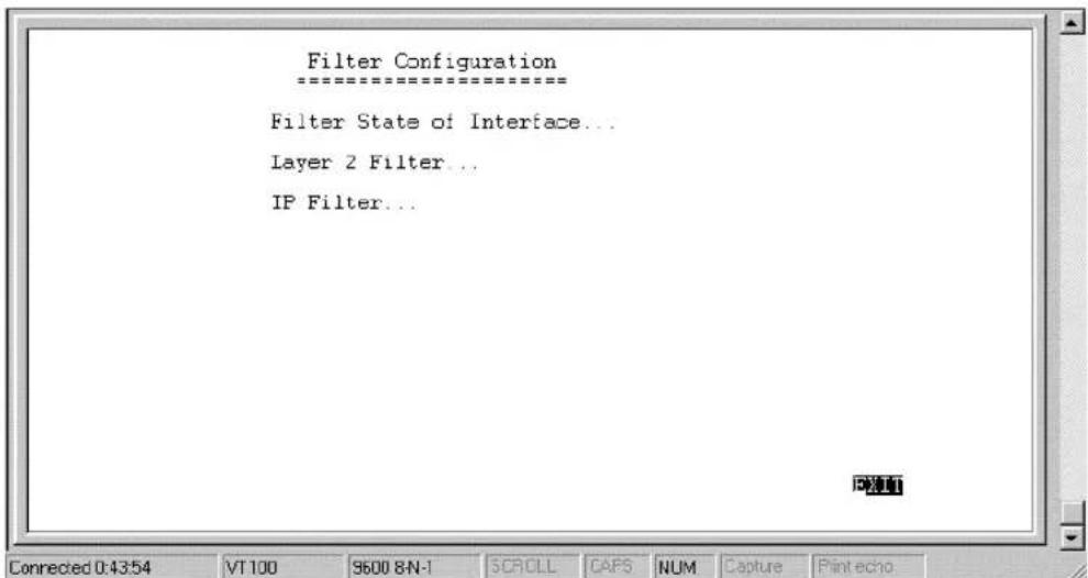
The three sub-menus are described as follows:
? ? Filter State of Interface – this is used to choose the default, routing decisions for packets, not meeting the criteria for specific filters.
? ? Layer 2 Filter – this is a data-link layer (protocol independent) filter. Foreknowledge of the specific protocol, used on the interface (LAN or WANs), is needed to make effective use of this filter.
? ? IP Filter – this is an IP protocol specific filter, allowing you to, among other things, prohibit specific packets from entering the LAN. Alternatively, you can set up filters that allow certain types of IP packets to enter the LAN.
Filter State of Interface
The Filter State of Interface sub-menu lets you toggle default, routing decisions, if the packets are not subjected to a filter, routing decision. In other words, a packet, having not met the criteria for a specific filter that was applied to a specific interface, will be subjected to this default, routing decision.
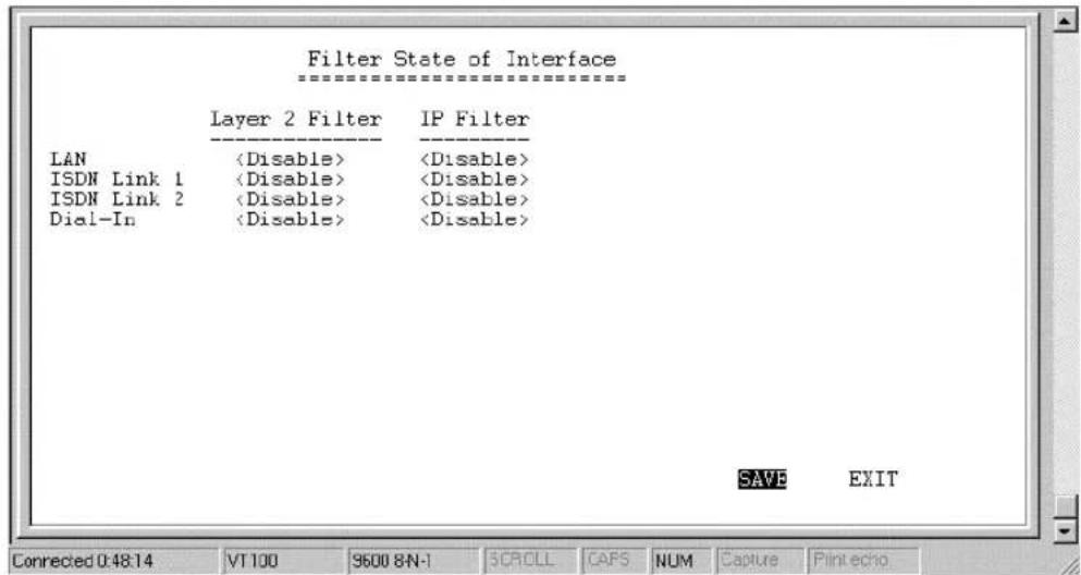
Each decision on handling packets is described below:
- Disable – will not apply a filter.
- Forward – this allows the routing of a packet, even though it has not met the criteria of the corresponding filter.
- Drop – this drops (doesn't allow routing for) a packet that has not met the criteria for the corresponding filter.
Layer 2 Filter
The Layer 2 Filter sub-menu contains a protocol independent (data-link layer) filter. Foreknowledge of the specific protocol used on the interface (LAN or WANs) is needed to make effective use of this filter.
![Name [ ] Direction State Interface Offset [0 ] Length [0 ] Value 0x[0000000000000000] Mask 0x[0000000000000000] SAVE Connected 0:49:14 VT100 9600 8N-1 SCROLL CAFS NUM Capture Print echo](/content/2026/06/1189103/images/83f9b3ad8e5e0b49790052f3a70b20cda5516da0cf05a9fd04579b5928671409.jpg)
The parameters of a filter are described below:
?? Name – this is a 12 character (maximum), alphanumeric, user-defined name, used to identify the filter.
?? Direction - this defines the direction of the frame relative to the Interface parameter below.
?? State – this is used to choose the routing decision applied to the frame. The three decisions are described:
- forward - this allows the routing of the frame, if it has met the criteria of the corresponding filter.
- drop - this drops (doesn't allow routing for) a specific frame that has met the criteria of the corresponding filter.
- disable - this does not apply the protocol independent filter.
?? Interface – this applies the filter to a specific interface, either LAN or one of the ISDN interfaces.
?? Offset – this defines the reference byte for the Length parameter (described below). The Offset is the number of bytes (octets) from the beginning of the first byte of the frame header, immediately after the preamble. The range of the offset parameter is from 0 to 255 octets. The first byte in a packet has an offset 0.
?? Length – this is the number of bytes (octets) from 0 to 8 to compare from the offset value (the Offset reference byte).
?? Value - this is a 16 digit, hexadecimal field, defining the actual bit values used to compare with the frame data, at the specified (Offset) position.
?? Mask – this is a 16 digit, hexadecimal bit mask, used as an operand in the bit-wise AND operation that will be applied to the Value parameter.
IP Filter
The IP Filter is specifically an IP protocols filter, allowing you to, among other things, firewall your network, prohibiting specific packets from entering or going out from your network. It is necessary to have good knowledge of IP protocol before effectively configuring this filter.
![Name [ ] Direction State Interface Protocol Type [6 ] Src IP [0.0.0.0 ] Src Netmask [0.0.0.0 ] Dst IP [0.0.0.0 ] Dst Netmask [0.0.0.0 ] Dst Port [0 ] Operation ICMP Type [1 ] ICMP Code [0 ] TCP Flag 0*[1 ] SAVE EXIT Connected 0:52:05 VT 100 S600 8-N-1 SCROLL CAPS NUM Capture Print echo](/content/2026/06/1189103/images/837a4ce619541a5664dd03bc6983ad6fe3f4b23e3d00d4e850f3706d0f6d01a6.jpg)
The IP Filter parameters are described below:
?? Name – this is a 12 character (maximum), alphanumeric, user-defined name, used to identify the filter.
?? Direction - this defines the direction of the packet relative to the Interface parameter below.
?? State – this is used to define the routing decision applied to the packet. The three routing decisions are described:
-
forward - this allows the routing of the packet, if it has met the criteria of the corresponding filter.
-
drop - this drops (doesn't allow routing for) a specific packet that has met the criteria of the corresponding filter.
-
disable - this does not apply the IP filter.
?? Interface – this applies the filter to a specific interface, LAN or one of the ISDN interfaces.
?? Protocol Type – this is a protocol identifier, as assigned by the Internet Assigned Numbers Authority (IANA). The values of this identifier are described in RFC-1700. This router supports the following:
-
protocol type = 1, this is Internet Control Message (ICMP), defined in RFC 792.
-
protocol type = 6, this is Transmission Control (TCP), defined in RFC 793.
-
protocol type = 17, this is User Datagram (UDP), defined in RFC 798.
?? Src IP – this is the source address in the IP header of this packet.
?? Src Netmask – this mask is bit-wise AND'd with the source IP address and bit-wise AND'd with the IP address of the incoming interface. The two results are then compared.
?? Dst IP – this is the destination address in the IP header of the packet.
?? Dst Netmask – this mask is bit-wise AND'd with the destination IP address and bit-wise AND'd with the IP address of the incoming interface. The two results are then compared.
?? Dst Port – this is the destination port, in the TCP or UDP header, of the packet.
?? Operation – this comparison operation is applied to the destination port (the Dst Port parameter) value, of the TCP or UDP header.
?? ICMP Type – this is the type field, in the ICMP header, used to identify a particular ICMP message.
?? ICMP Code – this is the code field, in the ICMP header, used to further specify the ICMP type.
?? TCP Flag – this is a hex number, representing the six flag bits in the TCP header. The value range is from 0 to 3F.
Multiple Home Configuration
Besides the IP address assigned to the LAN interface in the Network Configuration menu, the LAN may have up to 3 additional IP interfaces. These additional IP interfaces are referred to as MIP1 to MIP3. This type of configuration is known as a multiple home configuration.
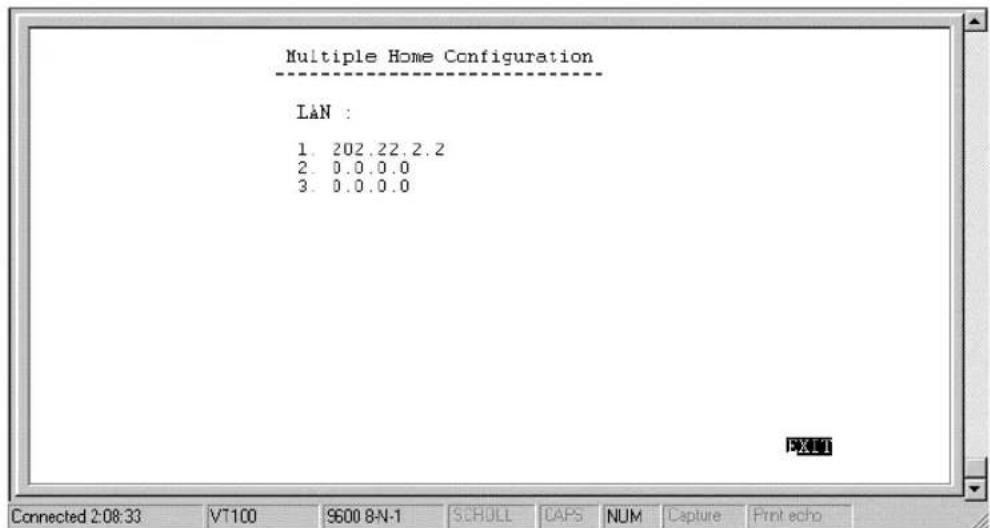
Multiple Home can be demonstrated by this example:
A company has 625 users (computers) all connected to one physical network using Ethernet. However, the company only has one Class C IP network address, 202.100.160.0. This network address will only support 254 users. To solve the shortage of IP address problem and to plan for future growth, the company applies for and receives two more Class C IP network addresses, 203.101.161.0 and 204.102.162.0. This gives the company a total of 254 × 3 = 762 IP Addresses, which it assigns to the computer users, with a few left over for future needs. Due to the nature of IP networks, however, the users in one IP network domain (202.100.160.0, for example) cannot communicate with users on a different IP domain (203.101.161.0). Multiple home solves this problem. When you register the additional IP network addresses in the Multiple Home Configuration menu on the router, the router will route data between the three IP networks using the single LAN.
In this router, multiple home configurations only apply to the LAN interface.
![IP Address [202.22.2.2] Netmask [255.255.255.0] Routing Protocol Routing Mode IF Multicasting Multicast Protocol IGMP Version SAVE Connected 0:46:31 VT 100 9600 8N-1 SCROLL CAPS NUM Capture Print echo](/content/2026/06/1189103/images/e7b8c8866b474a5bd7304963d2f7d4cc911d46ba23f4551973d3cedc7c50e44a.jpg)
The parameters are described below:
?? IP Address – this is a network IP address of a separate IP network on the LAN.
?? Routing Protocol – this is the same as in the Network Configuration section. Keep in mind that these exchanges are made with adjacent routers on the LAN, if present.
?? IP Multicasting – this enables/disables IP multicasting on the IP network you are defining.
All other parameters (Netmask, Routing Mode, Multicast Protocol and IGMP Version) are identical to those in the Network Configuration, IP Stack Configuration, ISDN section.
Static ARP
This special function is intended to speed up the process of finding a host's Ethernet (MAC) address from its network address, and provides a special condition – any other host acting as an impostor by using the same IP address as the legitimate host, will be ignored by this router.
Basically, when a packet comes into the router from the ISDN line and is destined for a host on the LAN, the router will use information defined here to immediately send the packet to the host rather than send out an ARP request to find the host's MAC address.
![IP Address [0.0.0.0] MAC Address 0x[000000000000] State SAVE EXIT Connected 0:47:15 VT100 9600 8N-1 SCROLL CAPS NUM Capture Print echo](/content/2026/06/1189103/images/1a6ee0a283755426291703944f10e0ed6127299e4440afeecbf637443df40a1d.jpg)
The parameters are described as follows:
?? IP Address – this is the IP address of the host you wish to define a static ARP for.
?? MAC Address – this is the physical address of the host that is the authorized owner of the IP address.
?? State – this toggles enable, disable.
NAT Configuration
Network Address Translation (NAT) is a routing protocol that allows your network to become a private network that is isolated from, yet connected to the Internet. It does this by changing the IP address of packets from a global IP address usable on the Internet to a local IP address usable on your private network (but not on the Internet) and vice-versa.
NAT has two major benefits. First, NAT allows many users to access the Internet using a small number or even a single global IP address. This can greatly reduce the costs associated with Internet access and also helps alleviate the current shortage of Internet IP addresses. Secondly, the NAT process provides some security found in a firewall, hiding your local network from Internet users, providing a degree of security to your Internet connection.
To be successfully implemented, NAT should be used only when the majority of network traffic remains on the local network. In cases where a large percentage of network traffic is destined for the Internet, NAT can adversely affect the speed and performance of your Internet connection. Also, your network servers such as ftp servers, web servers or mail servers will probably need to be assigned static NAT IP addresses so their IP addresses remain consistent. This issue will be further discussed later.
Network Address Port Translation (NAPT) is a subset of NAT where many local IP addresses and their TCP/UDP port numbers are translated to a single global IP address and it's TCP/UDP port number. In this document, the term NAT will refer to both NAT and NAPT unless otherwise stated.
NAT can work in conjunction with DHCP. Thus, if both are enabled and properly configured, the DHCP server in the TW-H6W1IR will assign local IP addresses to computers on your network.
How NAT Works
In the most common NAT configuration, your network uses local IP addresses that are not valid on the Internet. Internet (global) IP addresses are unique, with no two devices have the same IP address. The local IP addresses can be freely assigned to computers on your network by your network administrator (within guidelines defined later in this chapter and in Appendix B, IP Concepts). This can be done manually or by using DHCP. The ISDN port on the router is assigned a globally unique IP Address that is valid on the Internet, since it will be sending and receiving data directly to the Internet and is therefore part of it. Please study the example diagram below carefully.
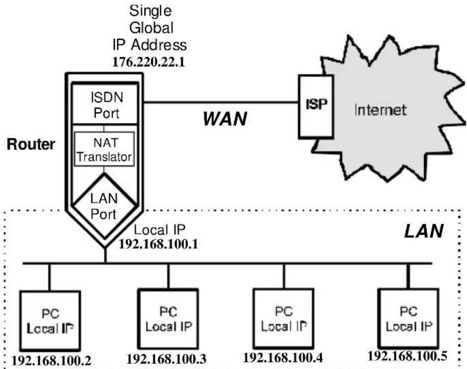
flowchart
graph TD
    A["Router"] --> B["ISDN Port"]
    A --> C["NAT Translator"]
    A --> D["LAN Port"]
    B --> E["ISP"]
    C --> E
    D --> E
    E --> F["Internet"]
    G["LAN"] --> H["PC Local IP 192.168.100.2"]
    G --> I["PC Local IP 192.168.100.3"]
    G --> J["PC Local IP 192.168.100.4"]
    G --> K["PC Local IP 192.168.100.5"]
    L["Single Global IP Address 176.220.22.1"] --> A
    M["Local IP 192.168.100.1"] --> A
Please note that in the above diagram, the Gateway IP address settings for the local PC's needs to be set to 192.168.100.1, the LAN IP address of the router.
NAT manipulates the IP addresses in packet headers on a one-to-one basis. An outgoing data packet (a packet originating from a computer on the local LAN and destined for a computer outside the private network) will have its IP address translated as shown below.
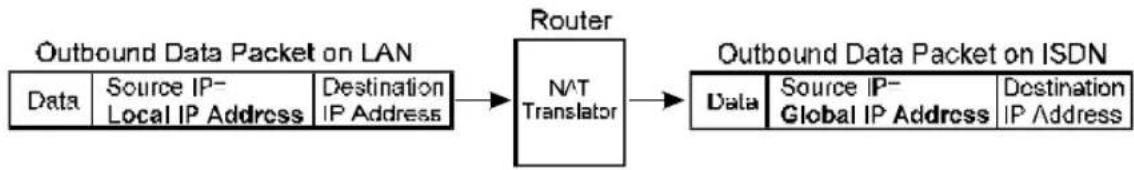
flowchart
graph LR
    A["Outbound Data Packet on LAN"] --> B["Router"]
    B --> C["Outbound Data Packet on ISDN"]
    subgraph Data
        A1["Data"] --> A2["Source IP-Local IP Address"]
        A3["Destination IP Address"]
    end
    subgraph Router
        B1["NAT Translator"]
    end
    subgraph ISDN
        C1["Data"] --> C2["Source IP-Global IP Address"]
        C3["Destination IP Address"]
    end
In the Outgoing Data Packet above, the Source IP address is the IP address that is translated by NAT. The Destination IP Address is the IP address of a computer outside the private network, on the Internet for example. And the Data portion of the packet is the information payload borne by the packet, for instance a request to view a web page.
The router logs the changes made to the IP header in its NAT table. The NAT table enables the router to send replies back to the local computer as shown below.
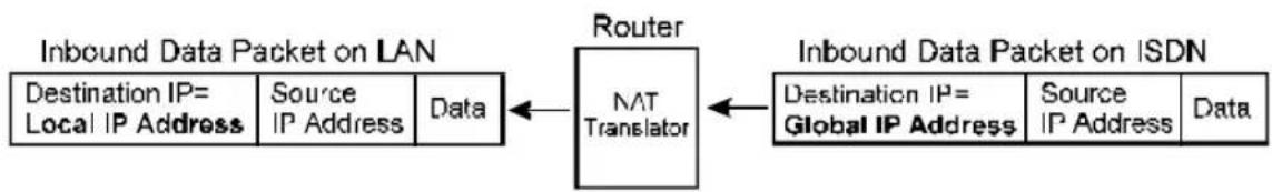
flowchart
graph LR
    A["Destination IP= Local IP Address"] --> B["Source IP Address"]
    B --> C["Data"]
    C --> D["Router NAT Translator"]
    D --> E["Destination IP= Global IP Address"]
    E --> F["Source IP Address"]
    F --> G["Data"]
    style A fill:#f9f,stroke:#333
    style G fill:#f9f,stroke:#333
In the Inbound Data Packet above, the Destination IP Address is the IP address that is translated by NAT. The Source IP Address is the IP address of a computer outside the private network. And the Data portion of the packet is the information payload borne by the packet, for example, the contents of a web page.
The actual information in the NAT table depends whether the router is implementing NAT or NAPT.
It is also of interest to note that this translation process provides a level of security to your network found in a firewall. If you examine the outbound and inbound packets above closely, you can see that the computer outside of the network that is receiving the packet and sending the response only knows about the global IP address used by the router, and actually sends the response to that address. The outside
computer has no knowledge of the internal local network. In fact, the local network is invisible to all computers outside of it, all information about it being stored in the router's NAT table. And this NAT table can only be affected by computers from inside the local network. The router will only add new entries or mappings to the NAT table when it translates addresses on outbound packets. Thus, all traffic must originate from inside the local network. If the router receives a packet from the outside (from an intruder attempting to gain access to your network, for example), the router will examine the source address of the packet and look for a match in the NAT table in it's attempt to deliver it to the correct local computer. Since no entry for this address exists in the NAT table, the router will drop this packet, denying the potential intruder of any access.
If you wish, however, to give access to one of your computers to people on the Internet (your company's web server, for example), then you must use a static NAT or NAPT assignment for them. When using static NAT, you would choose one of the global IP addresses at your disposal and map it directly to the local IP address of the web server. Thus, any packets coming from the Internet to that specific global IP address will always be routed to the web server. For static NAPT, you map specific global IP port numbers to the local IP address and port number. In both cases, the statically assigned IP address or port number is taken out of the pool that the router uses in the normal dynamic translation process, and the computer no longer benefits from the security provided by the address translation process.
NAT
This section discusses the NAT protocol as opposed to NAPT which is discussed in the next section.
NAT is the initial protocol set forth by RFC 1631 and provides a means in which private networks can communicate with the Internet by using a small number of IP addresses. In our discussion, we will use the example IP addresses listed in the table below and the network diagram shown on page 78.
| Global IP Addresses (for use with NAT) | Local IP Addresses (assigned to computers on the local network) |
| 200.100.50.1 192.168 | .100.2 |
| 200.100.50.2 192.168 | .100.3 |
| 200.100.50.3 192.168 | .100.4 |
| 200.100.50.4 192.168 | .100.5 |
| 200.100.50.5 192.168 | .100.6 |
| 192.168.100.7 | |
| 192.168.100.8 | |
| 192.168.100.9 | |
| 192.168.100.10 |
Please note that in the above table there are 9 users on the local network using 5 global IP addresses to access the Internet.
When a packet on the local network arrives at the router and needs to be sent to the Internet, NAT will change the source IP address (for example 192.168.100.2) to a global address (200.100.50.1, for example). If this packet generates a reply (as for example, a request to view a web page will), NAT will change the destination IP address on the reply packet back to the local IP address for delivery to the machine on the local (stub) network.
The difference between static and dynamic NAT is that once the five global addresses are manually assigned when using static NAT, they will never change. The only way to change them is by using the console program to manually reassign them. When using dynamic NAT, the router will map a local IP address to a global IP address whenever a request is made. Since there are only 5 global IP addresses in the example above, there can only be 5 mappings at any one time. In other words, much like static NAT, only 5 local machines can access the Internet at any one time. However, contrary to static NAT, the router will discard the mapping between the global and local IP addresses after a certain length of time (which is quite long so rarely happens), or after the session is finished (an example of a session is when requesting a web page, the entire page has completed downloading). The most common implementation of NAT is to define a range of dynamic addresses to be used by hosts, but assign static addresses to your servers if you wish for them to be accessible from outside your network.
NAPT
NAPT is an advanced version of NAT that uses IP port numbers in the network address translation process. It is much more widely implemented on networks today due to the fact that it uses only a single global IP address (as opposed to NAT which uses a range of global addresses), thus providing greater cost savings. For Internet access for everyone on the network through a single IP address (a single user account), NAPT is the right choice.
When a packet on the local network arrives at the router and needs to be sent to the Internet, it already has a (local) source IP address and a (local) source port number that was generated when the packet was
made. The router translates the IP port number to a unique (global) IP port number that the router generates itself (outside the range of Well-Known IP Port Numbers that are used for other network protocols such as html, telnet, etc.). The global port number and the global IP address are transcribed onto the packet (replacing the local numbers), and the packet is sent. The router then adds these values to it's NAPT table as shown in the example entry below.
| Source Port (local) | Source Port (global) | Source IP (local) |
| 80 6000 19 | 2.168.100.2 | |
The reply packet received by the router will be addressed to the global IP address and the global port number. The router then searches the NAPT table to match the IP port number from which it learns the local destination IP address and port number for the packet. It then translates the IP address and port number of the packet to their local equivalents and delivers it to the local host. Since all reply packets received by the router from the Internet are addressed to the single global IP address being used, the port number is the decisive parameter telling the router which local computer to route the packet to.
The above process describes dynamic NAPT. Static NAPT allows you to map specific global IP port numbers to local IP addresses and port numbers for certain applications that need to use specific port numbers, such as web servers (port 80), telnet servers (port 23), etc. Some Well-Known IP Port Numbers are provided in Appendix C – IP Protocol and Port Numbers, and a complete list can be found in RFC 1700. Some software applications (such as Microsoft NetMeeting,
CUSeeMe and Diablo) require specific port number translations, access to a range of port numbers, or no port number translation at all. The router can be configured for these types of applications using the Configure NAPT for Special Ap[lication]s submenu which is further described below.
As with NAT, defining static NAPT entries negates the security inherent in the NAPT process. However, only the specific port on the computer associated with the Static NAPT entry is accessible to users outside your network. In any case, whenever Static assignments are used, we highly recommend using alternative security measures such as filters and/or security features in the application software.
Setting Local IP Addresses
When implementing NAT and thus creating a private network that is isolated from the Internet, you can assign any IP addresses to host computers without problems. However, the Internet Assigned Numbers Authority (IANA) has reserved the following three blocks of IP Addresses specifically for private networks:
| Class | Beginning Address | Ending Address |
| A | 10.0.0.0 | 10.255.255.255 |
| B | 172.16.0.0 | 172.31.255.255 |
| C | 192.168.0.0 | 192.168.255.255 |
It is recommended that you choose local IP addresses for use with NAT from the private network IP addresses in the above list. For more information on address assignment, refer to RFC 1597, Address Allocation for Private Internets and RFC 1466, Guidelines for Management of IP Address Space.
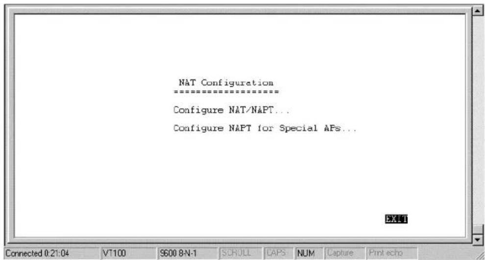
Configure NAT/NAPT
The first screen shows the complete NAT table that is defined by the network manager:
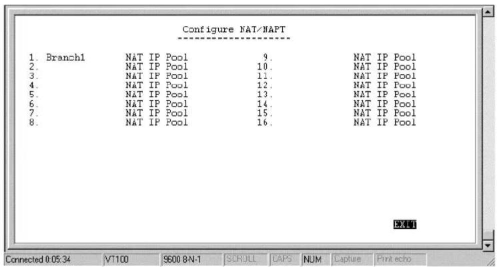
For any NAT entry, you must configure two different screens. The first one is accessible by positioning the cursor over the name field and
hitting ENTER (in the window shown above, this corresponds to the field ‘Branch1’). After configuring the NAT options in the Name field, you must save the changes, EXIT, and position the cursor over the NAT IP Pool to configure variables there.
Name Field Configuration Screen
The configuration screen for the name field appears as follows:
![Name [Branch1 ] Global Interface Local Interface Translation Mode State SAVE EXIT Connected 0:06:06 VT100 S600 8N-1 SCROLL CAPS NUM Capture Print echo](/content/2026/06/1189103/images/dbe77d34e4cf7158b531a1ea684fd43add3caaa30b74e31e3b26af75fddf559d.jpg)
The parameters are described as follows:
?? Name – this is a 12 character, alphanumeric, user-defined name, used to identify the network address translation.
?? Global Interface – this is the interface corresponding to the Global IP and Range parameters, in the NAT table, to form unique IP address[es], known to the outside (regional or Internet) routers, on this interface.
?? Local Interface – this is the interface corresponding to the Local IP and Range parameters, in the NAT table, to form local IP address[es], known only to this interface and the network within.
?? Translation Mode – this toggles choices of four types of NATs.
Static NAT – Maps one global IP address to one local IP address. After all global IP addresses are assigned, they will remain static. This option may be necessary for email, web, ftp servers, etc. where static IP addresses are essential for operation.
Dynamic NAT – Maps one global IP address to one local IP address. Global IP addresses will be dynamically reassigned to different local IP addresses if not currently being used. This allows a larger number of users to use a small number of IP addresses.
Static NAPT – One to one mapping of UDP/TCP port numbers to let packets with specific UDP/TCP port numbers enter the local IP domain. The NAPT map table will not age. This option may be necessary for email, web, ftp servers, etc. where static port numbers are essential for operation. Setting the global port number to 0 opens port numbers 1024 to 65535 for the designated local IP address, creating a visible computer. This allows a computer to be freely accessed by other computers on the Internet, which is necessary for some applications to function correctly when using NAPT, including Microsoft NetMeeting, CUSeeMe, etc.
Dynamic NAPT - One to one mapping of UDP/TCP port numbers. The NAPT map table will age. This option allows many hosts to use a single, globally unique IP address.
?? State – enables/disables this NAT configuration.
NAT IP Pool Configuration Screen
Now you must select, enter, and configure the NAT IP Pool from the NAT Configuration sub-menu, shown below.
Dynamic NAT
This screen (below) is how the NAT IP Pool appears, if Dynamic NAT was chosen for the Translation Mode parameter. Each entry, in this configuration, can be used to map multiple, contiguous global addresses and local addresses to each other.
![Dynamic NAT Global IP Range Local IP Range State 1. [210.11.22.50] {10} [11.2.2.2] [100] 2. [0.0.0.0] [0] [0.0.0.0] [0] 3. [0.0.0.0] [0] [0.0.0.0] [0] 4. [0.0.0.0] [0] [0.0.0.0] [0] 5. [0.0.0.0] [0] [0.0.0.0] [0] SAVE EXIT7](/content/2026/06/1189103/images/2c5e36524980da7647d56d30f8bf8ded608a231fb2b93d79c361a1cf2f17c1b1.jpg)
The parameters are described below:
?? Global IP – an IP Address that is globally unique and valid on the Internet. It is the base, global address for the global addresses that
will be recognized by the interface in the Global Interface parameter.
?? Range – this is the range of contiguous, global addresses above (and including) the base Global IP.
?? Local IP – an IP Address that is only used in the stub domain since it is not unique. It is the base, local address for the local addresses that will be recognized by the interface in the Local Interface parameter.
?? Range – this is the range of contiguous local addresses above (and including) the base Local IP.
?? State – this toggles the enable, disable, for this NAT entry.
Dynamic NAPT
This screen (below) is how the NAT IP Pool appears, if Dynamic NAPT was chosen for the Translation Mode parameter. Each entry, in this configuration, can be used to map a single global address and multiple, contiguous local addresses to each other.
![Dynamic NAPT Global IP Local IP Range State 1. 210.11.22.3 [11.1.1.1] [10] 2. 210.11.22.3 [0.0.0.0] [0] 3. 210.11.22.3 [0.0.0.0] [0] 4. 210.11.22.3 [0.0.0.0] [0] 5. 210.11.22.3 [0.0.0.0] [0] SAVE BXITZ Connected 4:17:36 VT100 SEDE BN-1 HORU GFS NUM Capex Passafe](/content/2026/06/1189103/images/af82860740af8fd6d0147a8da5ce299067386a75abb7580bb991bd285d7c3d08.jpg)
All of the parameters are the same as in Dynamic NAT, except the Global IP is a solitary, global address.
?? Global IP – this is a single, globally unique IP Address of the global interface (the interface to which it is assigned, in this case, one of the ISDN interfaces) that is valid on the Internet.
Static NAT
This screen (below) is how the NAT IP Pool appears, if Static NAT was chosen for the Translation Mode parameter. Each entry in this configuration is used to map a single global IP address a single local IP address.
![Static NAT Global IP Local IP State 1. [210.11.22.4] [11.1.1.11] 2. [210.11.22.5] [11.1.1.12] 3. [210.11.22.6] [11.1.1.13] 4. [210.11.22.7] [11.1.1.14] 5. [210.11.22.8] [11.1.1.15] SAVE EXIT Connected 4:20:45 VT:100 SEDE BN-1 EBITI CIPS NUM Close Next](/content/2026/06/1189103/images/0bf61ffa4ad32eba0be017d9b0620d659ab8ad063653001b3bf32632154248cb.jpg)
The parameters are described as follows:
?? Global IP – this is a single, global IP Address that is valid on the Internet, or on the same subnet of the global interface.
?? Local IP – this is a single, local IP Address that is not valid on the Internet.
Static NAPT
This screen (below) is how the NAT IP Pool appears, if Static NAPT was chosen for the Translation Mode parameter. Each entry in this configuration can be used to map a global address and port to a local address and port. Notice that the global address will be the external IP address of the global interface.
![Static NAPT Global IP Port Local IP Port State 1. 210.11.22.3 [21] [1.1.1.5] [21] 2. 210.11.22.3 [0] [0.0.0.0] [0] 3. 210.11.22.3 [0] [0.0.0.0] [0] 4. 210.11.22.3 [0] [0.0.0.0] [0] 5. 210.11.22.3 [0] [0.0.0.0] [0] SAVE EXIT Connected 0:04:41 VT 100 S600 8-N-1 SCROLL CAFS NUM Capture Print echo](/content/2026/06/1189103/images/479fa1063abd24ed28d8946669b6e3c9117cd8d1a4059d2e69a05544b49f4246.jpg)
?? Port – this is a destination port number used by TCP and UDP to de-multiplex incoming IP packets.
In the above example, incoming packets with the global destination IP Address (211.11.22.3) and global destination TCP/UDP port (21) will be translated to a packet with the local destination IP Address (1.1.1.5) and local TCP/UDP port (21).
Port 21 is assigned to FTP servers. Please see Appendix C - IP Protocol and Port Numbers for more commonly assigned port numbers, or RFC 1700 for a more complete list.
Configure NAPT for Special Ap[plication]s
Some applications programs that are used over the Internet such as Microsoft NetMeeting, Diablo, CU See Me and Xwindows send information to a certain port number or within a specified range of port numbers. The exact port number used is specific to the application. However, if you find that you are having trouble using an application
over the Internet and you are using NAPT, you may need to exempt certain port numbers from the NAPT port translation process. Please refer to the user guide for the program to find out whether it transmits and receives data only through specified IP port numbers. In order for these programs to work with NAPT, the IP port numbers required by these applications must be entered in the Configure NAPT for Special APs screen shown below.
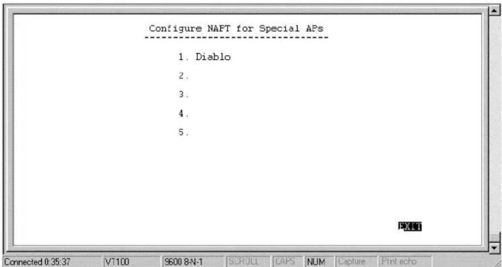
In the above window, position the cursor on any of the numbered name fields and press Enter. This will take you to the NAPT configuration screen for special applications shown below.
![Application Name [Diablo ] State Protocol Start Port End Port Connection Type 1. [6112] [6112] 2. [6112] [6112] > 3. [0] [0] > 4. [0] [0] > 5. [0] [0] > 6. [0] [0] > 7. [0] [0] > 8. [0] [0] >](/content/2026/06/1189103/images/337fd2f7494f975919ab9150342717cc77bde4a33b13330915fc43b3bef36336.jpg)
The fields in the above window are described as follows:
?? Protocol – [UDP] or [TCP]. This field designates the type of packets that will be acted on.
?? Start Port – Some applications can only send data over a certain range of port numbers. Thus, all port numbers in the specified range must be exempt from the NAPT port translation process. This field defines the beginning range of the port numbers to be exempted from the NAPT port translation process.
?? End Port - This field defines the last port number in the range of numbers excluded from the NAPT process (see Start Port above).
?? Connection Type – [Outgoing Control] or [Incoming Data]. The user must initially run the special application and send a request to the application server on the Internet. This outgoing request to join a Diablo server, for example, is used to trigger the exemption process for the incoming data.
In the example for the game Diablo shown in the above screen, if a packet is sent out on the TCP port number 6112 (a request by a local user to a Diablo server on the Internet to join a group game), all incoming packets on the UDP port 6112 (game data) will not be translated by NAPT.
Please keep in mind that the user will always initiate use of the special application. Thus, the first entry should always have the Connection Type of Outgoing Control. Also, since the defined port number or range of port numbers will be mapped to the user who triggered the outgoing control, all incoming data will be sent to that user.
Consequently, only one user can use the special application at a time.
Telnet/Discovery Enable
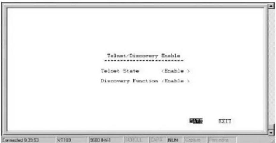
Telnet State - This feature enables or disables the router's ability to be configured over the LAN using telnet.
Discovery Function – Enabling this feature allows the router to be auto-discovered by TRENDNET SNMP management software and the included Windows-based configuration software called RouteMan.
DNS Configuration
The TW-H6W1IR router has a built in recursive DNS server. The maximum amount of memory that will be used by the router's Domain Name Server is 64Kb which averages out to be about 800 entries. In other words, up to 800 domain names and their associated IP Addresses can be stored, which can significantly speed up access to those domains. The routers DNS table will age out about every 24 hours, ensuring that the most frequently accessed domains consistently benefit from the improved access times provided by using the routers own DNS.
The IP Addresses for domain names not stored in the router must be acquired from a DNS server on the Internet. Thus, if you are using DNS, make sure you also specify an IP Address to a DNS server in the Forward DNS queries to field.
![DNS Configuration DNS Server State Lookup Host Table DNS Domain Name [ALL ] Forward DNS queries to [144.13.12.1 ] DNS Cache State Host Table... SAYT EXIT Connected 4:48:43 VT100 9500 8-1-1 SCROLL CAPS HMO CACCA PAPC00](/content/2026/06/1189103/images/5e1f28e9259af10ed26bfa016b29c0bb9bd478f59525549c612f32c2adf2ff05.jpg)
The items in the above submenu are described as follows:
? ?DNS Server State – enable/disables recursive DNS on this router.
? ?Lookup Host Table – enable/disables DNS to reference up to eight host names defined in the Host Table shown below.
? ?DNS Domain Name – the domain name suffix in which the router resides, to be appended to the host name defined in the host table.
? ?Forward DNS queries to – a large server dedicated to resolving domain names on the Internet. This field should contain the IP Address for the DNS closest to you.
? ?DNS Cache State – When this item is enabled, the router will add the domain names and IP Addresses it retrieves from DNS replies to its DNS cache.
Host Table
The host table allows the router to recognize host names on the network. Up to eight host names can be entered in the table. Your network servers, especially your mail server should be defined here. Leftover places in the table can be assigned to individual hosts to speed up routing.
In the example below, the host name ALL1 is combined with the domain name defined in the DNS Configuration submenu above (in this case, trendware.com) to produce ALL1.trendware.com. The mapping in the example of ALL1.trendware.com to the IP Address of 11.1.1.3 is only valid for computers which set the TW-H6W1IR router as their DNS server.
![Host Table IP Host Name State 1. [11.1.1.3] [ALLI] [] 2. [0.0.0.0] [] [] 3. [0.0.0.0] [] [] 4. [0.0.0.0] [] [] 5. [0.0.0.0] [] [] 6. [0.0.0.0] [] [] 7. [0.0.0.0] [] [] 8. [0.0.0.0] [] [] SAY2 EXIT Connected 4:55:54 VT100 96:00 8-N-1 BUPULL(GAP) NLM Capture FlowEcho](/content/2026/06/1189103/images/167c47a0922fcf0971b17fcc189bd7311a96f8ed56a2da6bba879f15c75c6f14.jpg)
Items are described as follows:
? ?IP – The IP address for the host.
? ?Host Name – the host name used by the host.
? ?State – Enables/disables entry.
Radius Configuration
Radius is an authentication protocol where passwords are stored on a Radius server. Radius allows large numbers of passwords to be stored in a centralized location. Before instituting Radius, please setup and install a Radius server on the LAN.
![RADIUS Configuration RADIUS State Type RADIUS Server IP Address [133.66.3.23 ] Port Number [1812 ] Key [ALL_customer ] SAVE EXIT Connected 45924 VT100 9600 B-N-1 SCROLL CAPS NUM Capture Rivercro](/content/2026/06/1189103/images/7ee32e155eda2ab3eb2750fa17ced9eaefaf177613a3830aabcad142a6df4962.jpg)
Items in the above submenu are described as follows:
? ?RADIUS State – enables/disables Radius. When enabled, all settings in the Dial-in User Profile are disabled.
? ?Type – refers to the type of external password protocol. Currently, only Radius is supported.
? ?Server IP Address – this is the IP Address of your UNIX or NT-based Radius server.
? ?Port – the port number for the Radius server. The standard port number specified by RFC 1700 is 1812 (shown above).
? ?Key – this is a shared secret used to identify the router as a valid Radius client.
The Radius authentication service works for dial-in users only. Thus, when Radius is enabled, passwords for dial-in users will no longer be checked in the dial-in user profile. Instead, the authentication request
will be passed on to the Radius server. Remote networks (routers) dialing into the router will still be authenticated using the remote network profile.
PPP Configuration
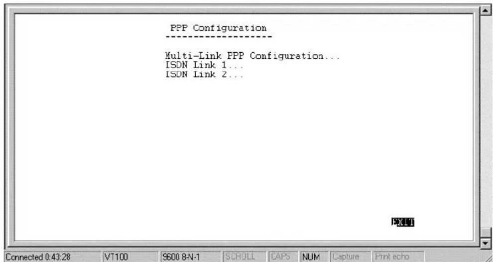
Multi-Link PPP (MLPPP)
Multi-link PPP (MLPPP) is a standard (RFC 1990 and RFC 1717) for inverse multiplexing, a method of combining individually dialed channels into a single, higher speed data stream. MLPPP is an extension of PPP that supports the ordering of data packets across multiple channels. Although MLPPP can be implemented on any WAN device, it was the rapid emergence of ISDN BRI as a cost efficient higher bandwidth alternative to modems which has driven the evolution and acceptance of MLPPP. Typically MLPPP is used to combine the speed of two ISDN BRI B-Channels to get 128Kbps of virtual capacity.
Before implementing MLPPP on the TW-H6W1IR, please ensure that your ISP or the device to which you are connecting supports, and is configured for MLPPP.
MLPPP can be implemented in two ways, dynamically through the use of the Bandwidth on Demand (BOD), and statically. BOD causes the second ISDN port to place a call and add bandwidth to the ISDN connection when the BOD High Threshold is exceeded for the Add Bandwidth Delay period. Bandwidth can also be subtracted when ISDN throughput falls below the BOD Low Threshold and Subtract Bandwidth Delay parameters. Thus, BOD economizes MLPPP by maintaining only the bandwidth needed.
A static implementation of MLPPP is achieved when BOD is disabled but the ISDN ports have Multi-Link enabled. In this case, when the two ISDN ports have established a connection, the router will check to see if they are connected to the same source and whether the source supports MLPPP. If both conditions are met, the router will automatically bundle the two links together as an MLPPP connection.
Choosing Multi-Link PPP Configuration displays the following screen:
![Multi-Link PPP Configuration Bandwidth On Demand BCD Criteria BCD High Threshold (#) [80 ] BCD Low Threshold (#) [20 ] Add Bandwidth Delay (sec) [5 ] Subtract Bandwidth Delay (sec) [10 ] BAVE EXIT? Connected 6:15:40 VT100 9600 8-N-1 SROLL CAPS HUM Capture PORTBON](/content/2026/06/1189103/images/709b3125945b703aa40762769645b0c5d9846edea41e5414b4d4e9c5c1e3a9a5.jpg)
Items in the Multi-Link PPP Configuration window are described as follows:
? ? Bandwidth on Demand – Enables/disables BOD. When enabled, BOD will manage the implementation of MLPPP using the parameters defined in this window.
? ? BOD Criteria – Either [TX], [RX] or [TX+RX], where TX is Transmit and RX is Receive. The parameter defined here is used when monitoring the BOD High Threshold and BOD Low Threshold.
? ? BOD High Threshold (%) – (0 to 100) The throughput value as a percentage of total bandwidth which will cause the next ISDN port having Multi-Link PPP enabled to dial up and add bandwidth to the connection. This value, however, must be constantly exceeded for the time designated in the Add Bandwidth Delay field before the next ISDN port dials out.
? ? BOD Low Threshold (%) – (0 to 100) The throughput value as a percentage of total bandwidth which will cause the highest numbered ISDN port in the MLPPP bundle to hang up, thus subtracting bandwidth from the connection. Before actually hanging up however, the throughput must be below this value for the time designated in the Subtract Bandwidth Delay field.
? ? Add Bandwidth Delay (sec) – (0 to 300) The amount of time in seconds the router will wait and sample the BOD Criteria before adding bandwidth once the throughput exceeds the BOD High Threshold. This prevents costly bandwidth from being unnecessarily added due to temporary bursts in traffic.
? ? Subtract Bandwidth Delay (sec) – (0 to 300) The amount of time in seconds the router will wait and sample the BOD Criteria before subtracting bandwidth once the throughput falls below the BOD Low Threshold. This prevents bandwidth from being unnecessarily subtracted due to temporary lulls in traffic.
The example Multi-link PPP settings shown in the Multi-Link PPP Configuration window above assumes that ISDN 1 and ISDN 2 each have a 64kbps connection configured to dial up to the Internet. When ISDN 1 receives a packet destined for the Internet it will dial the ISP and establish a connection. If the total throughput on ISDN 1 (TX + RX) ever exceeds 80% of the 64kps (51.2kps), the router will sample the line for an additional 5 seconds. If the traffic continuously exceeds 80% for the 5 second delay time, ISDN 2 will dial up and add bandwidth to the connection. Assuming sustained traffic of 70kps, MLPPP will balance the traffic on the two ISDN ports so they are handling roughly 35kps each. If the traffic on ISDN 1 + ISDN 2 falls below 20% of the 128kps connection (25.6kps) for more than 10
seconds, ISDN 2 will hang up and all traffic will be handled by ISDN 1.
For the above configuration to work, both ISDN ports need to have been properly setup to establish dial-out PPP connections, and have Multi-Link enabled. Also note that ISDN 1, being the B-channel that initiated the call in the MLPPP bundle and thus the primary link, is not subject to the BOD Low Threshold parameter and will never hang up due to BOD considerations. The primary link can, however, be subject to Dial on Demand (DOD) settings, and could thus disconnect if Dial on Demand is enabled and the Idle Time parameter is met. Dial on Demand settings are located in the Advanced Functions, Dial Configuration submenu.
ISDN Link 1 and 2
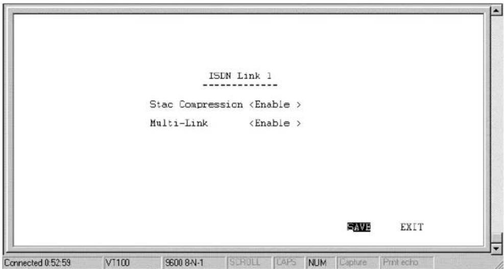
Stac Compression – this is an industry standard 4:1 compression scheme. When enabled, the router will try to use Stac compression on the designated ISDN port whenever possible. If the destination device
is not capable of using Stac compression, the two devices will still communicate, albeit without using Stac compression. When disabled, Stac compression will never be used on this port.
Multi-Link PPP – Enables/disables multi-link PPP on this port. Individual ISDN ports can be set to join the MLPPP bundle by enabling Multi-Link on each port. When enabled, the port will join the MLPPP bundle. Please note that the TW-H6W1IR contains only one MLPPP bundle. All ports taking part in MLPPP, even the first or primary port which initially establishes the connection, must have Multi-Link enabled. The ISDN port that first established the connection is the Primary ISDN Port and will not disconnect due to a BOD Low Threshold event, but is subject to Dial on Demand (DOD) settings.
Admin[istration] Configuration
This feature allows you to define two names and passwords used to login to the router for configuration and management, and is shown below:
![Admin Configuration Name Password Admin [Admin ] [ ] Guest [Guest ] [ ] SAVE EXIT7 Connected 1:41:53 VT100 960E 8N-1 CROLL CFF NUM Draw Passafe](/content/2026/06/1189103/images/7ed9ef1d2a6adfdbd43baf49d98b019eae3f1035ec333c1628cb3b50fa241fd2.jpg)
Please note any changes made here as they are necessary for logging into the console program.
System Maintenance
Your console program includes many useful tools for maintaining your device. These tools include updates on system status, upgrades to the system software, analysis, diagnostic tools and more. This section will describe how to use these tools in greater detail.
The System Maintenance sub-menu appears as follows:
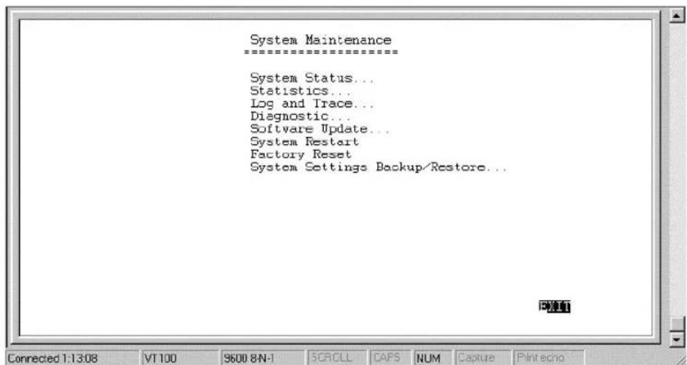
System Status
The System Status submenu displays key information about the router and appears as follows:
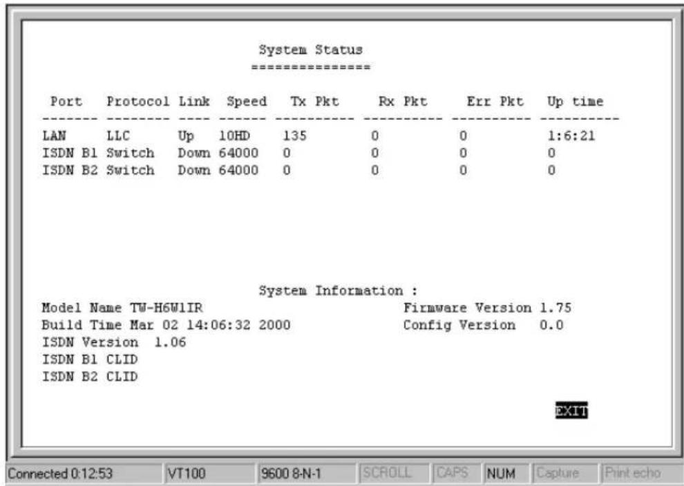
Statistics
Under the Statistics submenu, the routing table and routing statistics for each interface are displayed.
Routing Table
The Routing Table gives you a snapshot of the IP routing table. Table entries will expire after the Age value in the table counts down to zero seconds (except for entries for the router itself which have an age value of zero but will never expire).
| IP Address | Netmask | Gateway | If | Hops | Age |
| 0.0.0.0 | 0.0.0.0 | 172.22 3.1 | ISDN L1 | 1 | 0 |
| 10.0.0.0 | 255.0 0.0 | 10.2.77.80 | IAN | 1 | 0 |
| 100.0.0.0 | 255.0 0.0 | 10.16.79.1 | IAN | 3 | 31 |
| 202.12.124.0 | 255.255.255.0 | 202.12 129.1 | ISDN L2 | 1 | 0 |
| 202.12.125.0 | 255.255.255.0 | 210.172.23.1 | IAN | 1 | 0 |
| 202.22.2.0 | 255.255.255.0 | 202.22 2.2 | MIP1 | 1 | 0 |
| 202.39.74.0 | 255.255.255.0 | 10.16.79.1 | IAN | 2 | 31 |
| 210.68.85.0 | 255.255.255.0 | 10.16.79.1 | IAN | 2 | 31 |
?? IP Address – this is the destination, network IP address from an incoming packet.
?? Netmask – this mask is received from RIP exchanges and internal calculations, as the router learns.
?? Gateway – this is the next-hop router for which the packet, with destination IP Address and qualifying Netmask, will be forwarded.
?? If – this is the outgoing interface for which the acceptable, routing packet will be forwarded.
?? Hops – this is the remaining hop-count.
?? Age – this is the time-to-live (TTL) value.
Counter
This feature displays some of the counters contained in MIBII and the proprietary MIB. The table is updated every 5 seconds, and the counter table can be reset by performing a system reset on the router. Note that performing a system reset clears ALL tables in the router, including the routing table.
LAN Counter Table
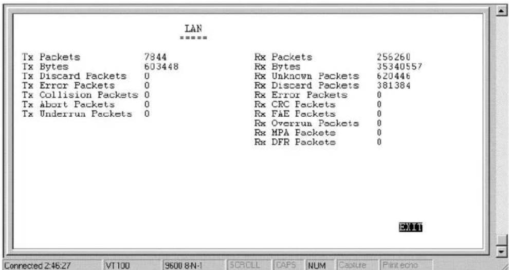
Tx Packets – the total number of valid packets transmitted by the router since the last reset.
Tx Bytes – the total number of bytes transmitted by the router.
Tx Discard Packets – the number of packets dropped by the router.
Tx Error packets – the number of invalid packets transmitted by the router. This hardware counter shows the sum of Collisions, Abort and Underrun packets.
Tx Collision Packets – the number of packets sent out of the router that collided on the line. Some collisions are inevitable due to the shared nature of Ethernet. Excessive collisions show excessive utilization of the network.
Tx Abort Packets – When the router transmits a packet and a collision occurs, the router will wait a random period and try to retransmit the packet. If a collision occurs 16 times in a row, the transmission will be aborted and be logged by this counter. An aborted packet shows extremely heavy utilization of the network.
Tx Underrun Packets – Runt packets. The number of packets transmitted by the router that are less than the allowed 64 octets minimum length. Underrun packets occur due to jam signals generated by collisions, backpressure, etc.
Rx Packets – the number of valid packets received by the router.
Rx Bytes – the total number of bytes contained in the valid packets received by the router.
Rx Unknown Packets – the number of packets received by the router that were of an unsupported protocol.
Rx Discard Packets – the number of packets dropped by the router.
Rx Error Packets – the number of invalid packets received by the router. This hardware counter shows the sum of CRC, FAE, Overrun, MPA and DFR error packets.
Rx CRC Packets – the number of packets received that failed the CRC checksum test.
Rx FAE Packets – Frame Alignment Error. The number of packets received that does not end on a byte boundary and the CRC does not match.
Rx Overrun Packets – the number of packets received that exceed the 1518 octet maximum length imposed on Ethernet packets. Overrun packets are generated by some proprietary software applications.
Rx MPA Packets – Missed Packet. This is a count of packets intended for the router, but at the time, the router could not receive the packet (usually due to the temporary lack of receive buffers).
Rx DFR Packets – Deferred Packets. This is a count of incidents where CRS (carrier signal lost) and COL both occur at the same time. These two events happen simultaneously as a result of jabber (produced by faulty networking equipment, usually NIC's).
ISDN Counter Table
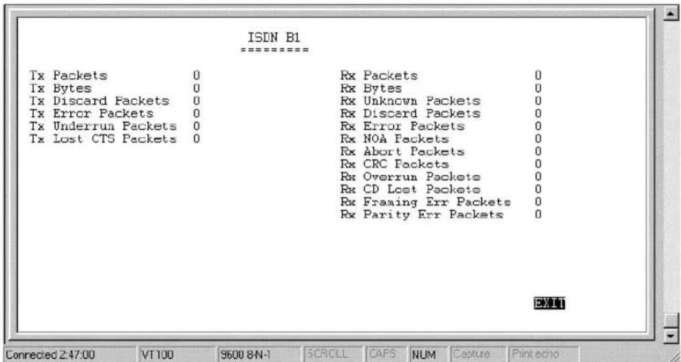
Tx Packets – the total number of valid packets transmitted by the router since the last reset.
Tx Bytes – the total number of bytes transmitted by the router.
Tx Discard Packets – the number of packets dropped by the router.
Tx Error packets – the number of invalid packets transmitted by the router. This hardware counter shows the sum of Collisions, Abort and Underrun packets.
Tx Underrun Packets – Runt packets. This counter shows the number of packets transmitted by the router that are less than the allowed 64 octets minimum length. Underrun packets occur due to jam signals generated by collisions, backpressure, etc.
Tx Lost CTS Packets – the number of Clear To Send packets that were lost by the router.
Rx Packets – the total number of packets received by the router.
Rx Bytes – the total number of bytes contained in packets received by the router.
Rx Unknown Packets – the number of packets received by the router that were of an unsupported protocol.
Rx Discard Packets – the number of packets dropped by the router.
Rx Error Packets - number of invalid packets received by the router. This hardware counter shows the sum of NOA, Abort, CRC, Overrun, CD Lost, Framing and Parity error packets.
Rx NOA Packets – Non-Octet Alignment. This counts the number of packets received by the router that did not end on a byte
boundary. The receipt of a misaligned packet will generate a single NOA event regardless of the number of misaligned octets in the packet.
Rx Abort Packet – the number of packets that were dropped due to user generated breaks in the transmission that occurred while a packet is being received.
Rx CRC Packets – the number of packets received that failed the CRC checksum test.
Rx Overrun Packets – the number of packets received that exceed the 1518 octet maximum length imposed on Ethernet packets. Overrun packets are generated by some proprietary software applications.
Rx CD Lost Packets – Carrier Detect Lost. This counts the number of Carrier Detect packets that were lost by the router.
Rx Framing Error Packets – Packets with framing errors can occur on the ISDN port only when using HDLC in sync mode. This parameter counts the number of lost start/stop flags.
Rx Parity Error - the number of times parity errors occurred on the line.
Log and Trace
This feature files events and errors that occurred and allows individual packets to be captured in a buffer. These items are to help TRENDNET technical support personnel identify problems that may be affecting your router. If problems occur with your router, TRENDNET technical support personnel will guide you through the use of these features.
Event/Error Log
Log Configuration
This option allows you to enable/disable the Event/Error log and begin recording events.
View Log File
This displays the Event/Error Log file shown below:
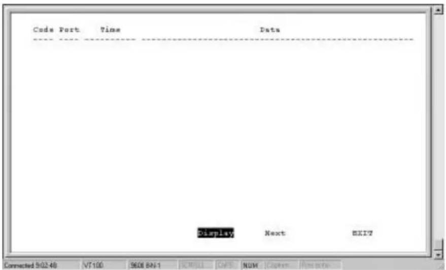
The parameters are described as follows:
? ?Code – A special code for categorizing events. Some codes include:
0 Cold Start
1 Link Change
2 Tx Abort
3 Rx Abort
4 Connect/Disconnect
5 NAT Request
6 DHCP Request
? ?Port – The interface on which an event occurs.
? ?Time - Tick-times denoting when events occurred.
? ?Data – Data that helps technical support personnel evaluate the event.
Trace Buffer
This feature captures packets in a buffer to help TRENDNET technical support personnel identify problems with your router.
Trace Buffer Configuration
Enables/disables the Trace buffer feature.
View Trace Buffer
Displays the header of packets captured in the buffer.
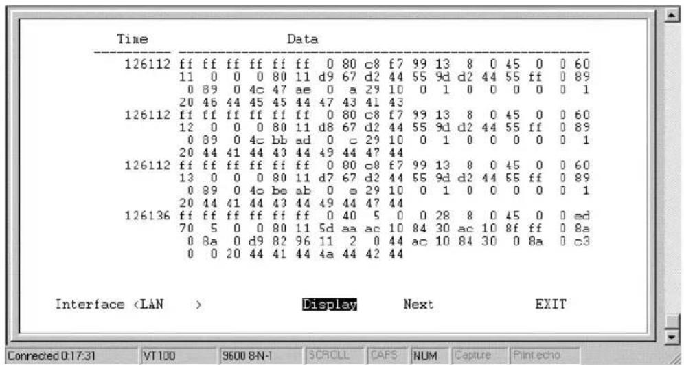
The contents are described as follows:
? ? Interface – This is the interface from which the packets were captured.
? ? Time – in clock ticks. The time the packet was captured.
? ? Data – the contents of the header of the packet.
Diagnostic
This feature tests the connection between the router and connected peripherals on a given interface.
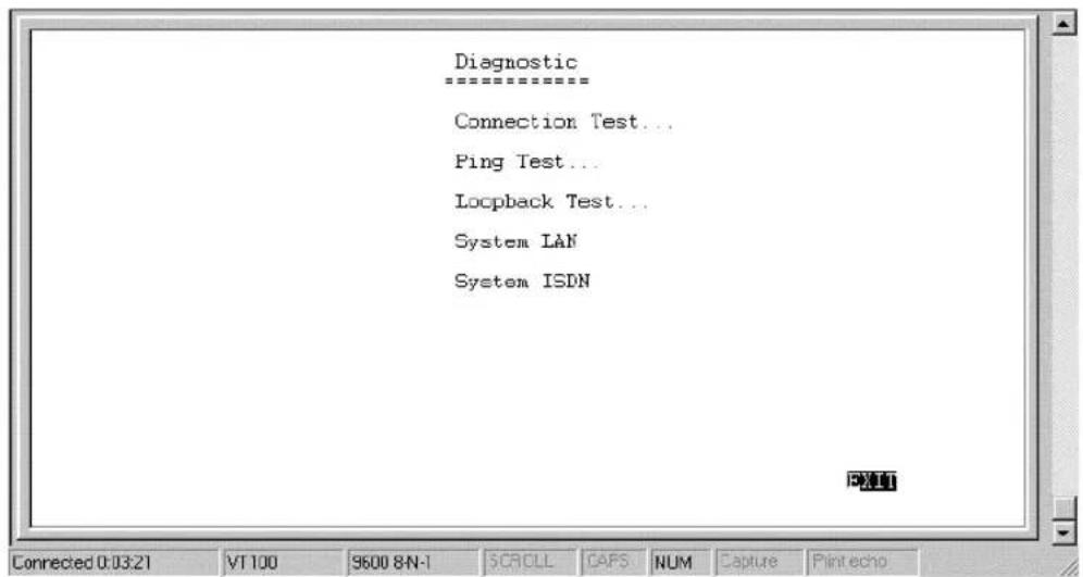
Connection Test
This feature tests a dial-out ISDN connection.
![Connection Test ==================== Interface Phone Number [5556969 ] Connection Test Dial Out Hang Up EXIT Connected 0:19:10 VT100 9600 8N-1 SCROLL CAFS NUM Capture Print echo](/content/2026/06/1189103/images/38210479efcaf752ee07b1fa17c8cdbc9f9a2b772935b4b71236c9aa6f280e86.jpg)
? ? Interface – The ISDN B-channel to be tested.
? ? Phone Number – The phone number that will be dialed by the ISDN Interface. Please ensure that a modem answers the phone on the other end.
? ? Connection Test – Position the cursor over this item and press
? ? Dial Out – Press
? ? Hang up – Press
Ping Test
This test makes sure there is an IP network connection to a particular IP address.
![Ping Test IP Address [172.45.200.2 ] Count [10 ] Delay (10ms) [2 ] Start Ping Test Connected 014 39 VT100 SEOE BN-1 IORLL GPS NUM Open New echo EXIT](/content/2026/06/1189103/images/1610a7f402b222a6c70b386f38f3828efb2d167da425cf45ca824c970462d492.jpg)
? ? IP Address – This is the IP Address of the device that the router will attempt to reach. The router will check it routing table and try to locate the IP Address.
? ? Count – The number of pings (packets) that will be sent. A value of 0 will cause pings to be sent continuously.
? ? Delay (10ms) – The amount of time in 10 millisecond intervals between each ping in the Count.
? ? Start Ping Test - Press
Loopback Test
The loopback test is used to test the path ISDN network between your phone company's switch and the router.
![Phone Number [5550069 ] Packet Length [64 ] Start Test EXIT Connected 2:51:21 VT100 9600 8N-1 SCROLL CAFS NUM Capture Print echo](/content/2026/06/1189103/images/37a3e02d2c9126982d765f611617dd5f91b09bf0cbbe473f3da814b9f481e6e8.jpg)
? ? Phone Number – Enter your own phone number here to establish a connection between your ISDN B1 and B2 channels.
? ? Packet Length – [1 to 1500 bytes]. This field allows you to define different sized data packets to test the ISDN line.
? ? Start Test - Press
System LAN Test
The System LAN test is used to diagnose the LAN port. It can only be run if the LAN port is disabled in the Interface Configuration submenu.
System ISDN Test
This test diagnoses the ISDN ports. It can only be run if the ISDN port is disabled in the Interface Configuration submenu.
Software Update
New routing software can be downloaded from a TFTP server. All configuration settings will be retained through the software update process.
If you do not have a TFTP server on your LAN, you can use RouteMan, the included Router Configuration Utility. This Web-based utility has a built-in TFTP emulator, which allows you to use the computer (connected to the LAN and running RouteMan) to upload the new software to the router.
![Software Update Menu Software Update Software Update Mode Network Boot Protocol Boot Server IP Address [10.2.77.2 ] Boot File Name [D:\ALL\runtime\image\ALLrun.sys ] Last Boot Server IP Address: 0.0.0.0 Update Software from Configuration File SAVE EXIT Connected 523.35 VT100 9600 BHH SCRILL CAPS NLM Capture Protects](/content/2026/06/1189103/images/f8133ef3c3f320d4761a823231d9b195766ed71720ae40b7ef579275290ae2bf.jpg)
This is the same Software Update configuration screen as in the PROM System Configuration, Software Update section. The parameters are described in that section.
Perform a System Restart after configuring these settings to begin the software update procedure.
System Restart
The system restart function enables you to reset the TW-H6W1IR without powering off. Some settings changes require a system restart in order for them to take effect.
A system restart will not affect the router's settings, but will clear all tables including the routing table and all SNMP counters and tables. It is also used to initiate a software update.
Factory Reset
Performing a factory reset erases all settings and tables. All configuration changes ever made to the router will be deleted. The router will be set to the factory defaults it was shipped with and will no longer have an IP address.
Please make sure you wish to wipe out all settings and configure the router from scratch before you perform a factory reset.
System Settings Backup/Restore
The backup and restore system settings function is used to backup the router settings. The file created by this process is different than a configuration file or the software update file that are used in the Software Update submenu. The file defined here can be used as a backup for all the router settings and can be used to configure another TW-H6W1IR with exactly the same settings, or as a backup before you make major changes to the configuration.
![Backup System Settings ==================== Remote IP Address [10.69.3.69 ] TPTP Time Interval [5 ] File Name [D:\SETTING8.BAR Start Backup BETT Connected 5:26:53 VT100 90:00 8-N-1 SCH(5) CAPS HUM Capture Print echo](/content/2026/06/1189103/images/bb3ac5850bc2139b6def8aa21d91a289200fc8418d655a1e635808f1505fbc8c.jpg)
Items in the window are described below:
?? Remote IP Address – this is the IP address of the TFTP server on which you wish to store the settings file.
?? TFTP Time Interval – the time between requests to occupy TFTP server time. If the router doesn't receive a response (ACK) from the TFTP server within the time interval defined here, it will assume the request has been dropped and send another.
?? File Name – specifies the complete path and filename on the TFTP server for the settings file.
PROM System Configuration
The PROM program is run before the normal console (runtime) configuration program in the router's Flash Memory. Thus, the PROM System Configuration can be used if there are problems with the router's console program.
Specifically, the PROM Configuration program has procedures to initialize the administration parameters and the LAN IP address of the router in order to allow the console software in the router's flash memory to be replaced if it has been damaged or deleted.
To enter the PROM System Menu, press Ctrl+C during the Router's POST procedure. The following menu will appear:
TW-H6W1IR Router - PROM System Menu
System Configuration
TCP/IP Parameters Configuration
System Reset
Software Update
Eeprom Factory Reset
Execute Bootload
System Configuration
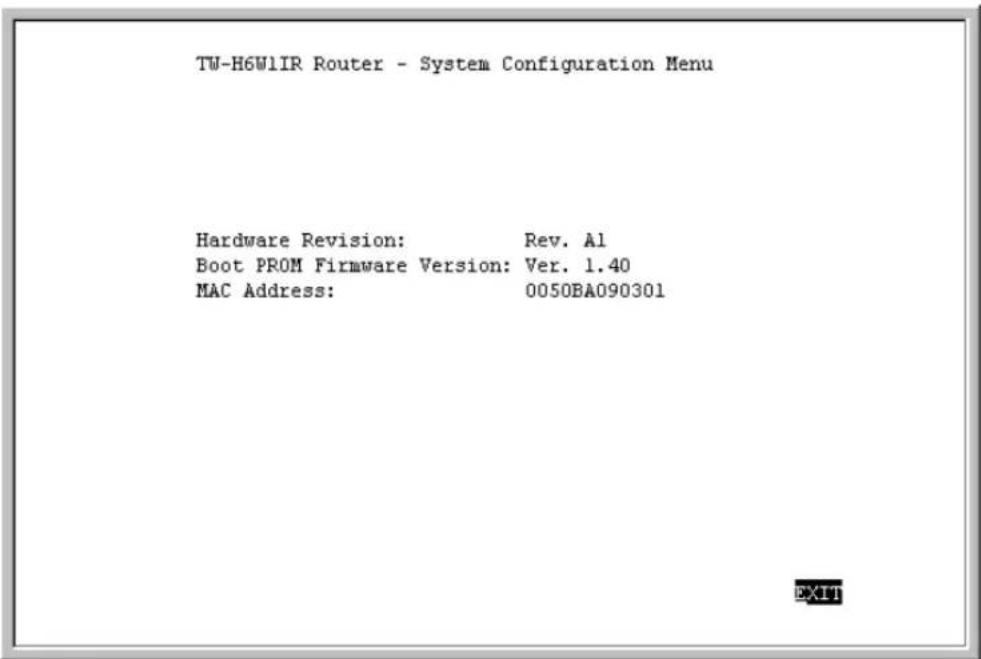
The parameters are described as follows:
Hardware Revision – this is the version ID of hardware used in this router.
Boot PROM Firmware Version – this is the version ID of firmware used in this router.
MAC Address – this is the physical address for this router.
TCP/IP Parameters Configuration
![TW-H6W1IR Router - TCP/IP Parameters Configuration Menu Interface # 1 Media Type: Ethernet IP Address [192.168.120.253] Subnet Mask [255.255.255.0 ] Default Gateway [0.0.0.0 ] Send BootP request upon power up HELP SAVE EXIT](/content/2026/06/1189103/images/c537533b179fdc36a102aabc02163c5b78049afcddd38204f1226190e011f23e.jpg)
The parameters are described as follows:
?? Interface – the LAN interface must use Ethernet/Fast Ethernet and is displayed here. This setting cannot be adjusted.
?? IP Address – this is the router's IP Address for the LAN interface.
?? Subnet Mask – this mask shows how the LAN is to be divided into network, subnet and host parts.
?? Default Gateway – this is the default gateway for the LAN. If this router will be the default gateway for the LAN, then the address should be 0.0.0.0.
?? Send BootP request upon power up – if set to YES, when the router boots up, it will attempt to acquire the path to the image file, the TFTP server IP Address and the routers own IP Address.
System Reset
The system reset function enables you to reset the TW-H6W1IR without powering off. Some settings changes require a system reset in order for them to take effect.
A system reset will not affect the router's settings, but will clear all tables including the routing table and all SNMP counters and tables. It is also used to initiate a software update.
Software Update
The routing/runtime software should only be updated if you are encountering problems with your current runtime software or you are certain your runtime software is lacking functionality contained in a more recent version.
Downloading new software will only replace the runtime software and will not affect any configuration settings you have made. Upon running the new software, the router will be configured exactly as you had it before downloading the new software.
The runtime software (image file) must be downloaded from a TFTP server on the LAN. If you do not have a TFTP server on your LAN, you can use RouteMan, the included Router Configuration Utility. This Web-based utility has a built-in TFTP emulator, which allows you to use the computer (connected to the LAN and running RouteMan) to upload the new software to the router.
![TW-H6W1IR Router - Software Update Menu Software Update Control Software Update Mode Network Boot Protocol Boot Server IP Address [192.168.120.2 ] Boot File Name [d:\work\Trend.sys ] Last Boot Server IP Address: 0.0.0.0 Last IP Address: 0.0.0.0 Update Software from Configuration file HELP SAVE EXIT](/content/2026/06/1189103/images/9a54cab6fe677c16549d83e547284e85ce2fa5aa07e8f8cd2d815eb018bd4afc.jpg)
Items listed in the above menu are described as follows:
?? Software Update Control – this enables/disables the software update process.
?? Software Update Mode – this specifies downloading the image file from a Network server on the local LAN.
?? Boot Protocol – this setting is for a local network download and has two options TFTP and BootP&TFTP.
?? TFTP – a File Transfer Protocol. Using this setting assumes all other items on this screen have been filled out.
?? BootP&TFTP – BootP is run first and sends your router IP Addresses for the TFTP server and the router, and tells the router the path to the software update (image file). Then TFTP will be used to download the image file.
?? Boot Server IP Address – this specifies the IP address of the server to be used to download the image file.
?? Boot File Name – this specifies a complete path and filename on the TFTP server. If you choose to use a configuration file, this setting must show the path and filename to the configuration file. If you are not using a configuration file, this must show the path and filename to the software update image file.
?? Last Boot Server IP Address – this shows the last boot server used to download an image file. This is for reference only.
?? Last IP Address – this shows the last IP address used for the LAN interface. Again, this is for reference only. The LAN port must have an IP address in order to access the TFTP server via the LAN network.
?? Update Software from Configuration File – Either YES or NO. If YES, the software update procedure will try to access a configuration file located at the path defined in the above Boot File Name. Please ensure that the path and file name of the software image file is listed in the configuration file. If set to NO, the update procedure will try to find an image file at the Boot File Name path. Please see Appendix F – Configuration File for more information about configuration files.
After the parameters are set in the Software Update screen, SAVE the changes, EXIT, and perform a System Reset or Execute Bootload to begin the software download process.
After the new runtime software has been downloaded, the router will automatically start up using the new software with the Software Update Control setting DISABLED to avoid a downloading loop.
EEPROM Factory Reset
Performing a factory reset erases all settings and tables. All configuration changes ever made to the router will be deleted. The router will be set to the factory defaults it was shipped with and will no longer have an IP address.
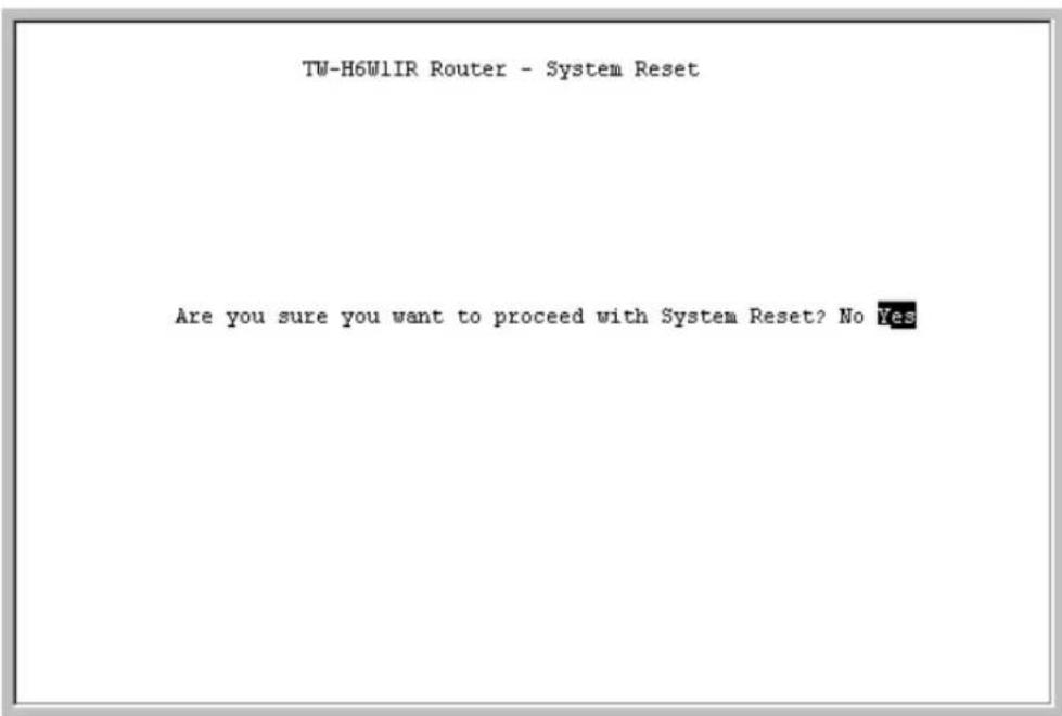
Please make sure you wish to wipe out all settings and configure the router from scratch before you perform a factory reset.
Execute Bootload
Choosing this option accepts the changes made in the PROM program and begins the router's startup sequence.
Executing a bootload can also begin the Software Update procedure, if enabled.
Using Telnet
The TW-H6W1IR router can be configured and managed using telnet. Telnet accesses the same built-in configuration program as the RS-232 Diagnostic port console connection. As such, all settings that can be adjusted through the console can also be configured using Telnet.
Telnet Configuration
In order to use telnet, the TW-H6W1IR router must first be configured using a console connected to the RS-232 Diagnostic port. Depending on the placement of the management station using telnet, the initial configuration requirements for the router are as follows:
Using Telnet via LAN
Preparing the router for management by telnet over the LAN only requires enabling the LAN port, enabling telnet, and assigning the LAN port an IP address. To do this:
-
Connect a console to the RS-232 Diagnostic port on the front panel of the router and run a terminal emulation program (for more information, see Connecting the Console to the Router and Setting Up the Console sections of this manual).
-
Enable the LAN port in the Interface Configuration sub-menu.
-
Assign an IP address to the LAN port in the Network Configuration sub-menu.
- Enable Telnet in the Advanced Functions submenu.
- Connect the router to the LAN.
The router can now be accessed via the LAN by the included Windows-based Configuration program, Telnet and SNMP management applications. For more detailed information regarding these procedures, please refer to the Connecting the Router section of this manual. For more information about the submenus, please refer to the Configuration and Management section of this manual.
Using Telnet via ISDN
Preparing the router for management by telnet over ISDN lines requires more initial configuring of the router via the console.
To do this, you must configure an ISDN port for dial-in users. Please refer to the Interface Configuration – ISDN Sub-menu section of this manual.
System Timeout
When you are connected to your TW-H6W1IR via Telnet, there is a system timeout (in the System Information sub-menu), adjustable to a maximum of 90 minutes. If you are logged onto the device and leave it inactive for this timeout period, the router will automatically disconnect you.
Using RADIUS Authentication
In addition to the dial-in user list, which can hold up to eight users, this model also supports an external authentication server which may provide password storage and usage accounting for thousands of users.
Installing a RADIUS Server
To use RADIUS authentication, you will need to have a UNIX or Windows NT-based machine on your network to act as a radiusd server, as well as a copy of the radiusd server program itself. You can obtain a copy of the RADIUS software, along with documentation for the server, at
http://www.livingston.com/marketing/products/radius.html
or at:
ftp://ftp.livingston.com/pub/le/radius/
Configuring the TW-H6W1IR for RADIUS Authentication
To configure the TW-H6W1IR to use the RADIUS server set up in the previous section, go to the Main Menu in the console program and choose Advanced Functions and then RADIUS Configuration.
![RADIUS Configuration RADIUS State Type RADIUS Server IP Address [133.66.3.23 ] Port Number [1812 ] Key [ALL_customer ] SAVE EXIT Connected 60314 VT100 9600 BN-1 CRDL CAPS PAL Capture Protect](/content/2026/06/1189103/images/53e44724d9c65d1abd4971962cf78a6c76925d5d768fd18236f274a0894227f2.jpg)
Items in the above submenu are described as follows:
? ?RADIUS State – enables/disables Radius.
? ?Type – refers to the type of external password protocol. Currently, only Radius is supported.
? ?Server IP Address – this is the IP Address of your UNIX or NT-based Radius server.
? ?Port – the port number for the Radius server. The standard port number specified by RFC 1700 is 1812 (shown above).
? ?Key – this is a shared secret used to identify the TW-H6W1IR as a valid Radius client.
The Key password should be stored in the client file in the RADIUS server's /etc/raddb directory. Lines of the form
# Client Name
Key
#----
192.168.0.1 ALL_customer
should be added to the client file. The Client Name field in the file gives the IP address of the TW-H6W1IR, and the Key field should be the same as the Key field in the Radius Configuration submenu.
After a RADIUS server has been configured, the TW-H6W1IR will use it to authenticate all users instead of checking it's internal Dial-Up User Profile.
Adding Users to the RADIUS Database
The TW-H6W1IR only uses the RADIUS database for user authentication. Except for the User Name, Password and Framed_IP_Address fields, most standard RADIUS attribute fields are ignored by the TW-H6W1IR.
To add a user to the RADIUS database, edit the users file in the RADIUS server's /etc/raddb directory, and add a line similar to the following:
joeuser Password = "joepassword"
Each user should have a user name/password record in the Users database. It is also possible to configure an IP address for each user by adding a line in the Users database similar to the following:
Ip user Password = "iusespecificip", Framed_IP_Address = 192.168.0.117
Appendix A - Troubleshooting
This chapter contains some problems you may run into when using your router. After each problem description, we have provided some instructions to help you diagnose and solve the problem.
Some Common Problems With the TW-H6W1IR
None of the LEDs are on when you power up the router
? ?Check the power cord and the power supply and make sure it is properly connected to your TW-H6W1IR. If the error persists you may have a hardware problem. In this case you should contact technical support.
Connecting the RS-232 cable, cannot access the console program
? ?Check to see if the TW-H6W1IR is connected to your computer's serial port.
? ?Check to see if the communications program is configured correctly. The communications software should be configured as follows:
?? VT100 terminal emulation.
?? 9600 Baud rate.
?? No parity, 8 Data bits, 1 Stop bit.
Problems With the ISDN Line
If you are having problems making a connection through the ISDN line, try performing a Loopback Test (in the console program choose System Maintenance, Diagnostic, Loopback Test). If the loopback test succeeds then your physical connection to your phone company is ok and the problem probably lies in your ISDN settings (located in the console program under Interface Configuration, ISDN). Alternatively, the problem could be with the router or computer you are trying to call.
Problems with the LAN Interface
Can't PING any station on the LAN
- Check the LAN LED on the front panel of your router. If it is on, then the link is up. If it is off, then check the cables connecting the router to your LAN.
- Make sure the LAN is enabled in the Interface Configuration, LAN submenu of the console program.
- Verify with your network administrator that the IP address and the IP subnet mask configured in the Network Configuration, IP Configuration, IP Stack Configuration, LAN submenu of the console program are valid for that LAN.
- Check the physical Ethernet cable, and make sure the connections on the router and the hub or station are secure.
-
Check to make sure an end station IS NOT connected to the Uplink port or that a hub IS connected to the Uplink port using straight-through cables.
-
Check to make sure the wires in the cable are attached to the appropriate pins in the RJ-45 connector
Appendix B - IP Concepts
This appendix describes some basic IP concepts, the TCP/IP addressing scheme and show how to assign IP Addresses.
When setting up the router, you must make sure all ports to be utilized on the router have valid IP addresses. Even if you will not use the ISDN or WAN ports, you should, at the very least, make sure the LAN port is assigned a valid IP address. This is required for telnet, in-band SNMP management, and related functions such as “trap” handling and TFTP firmware download.
IP Addresses
The Internet Protocol (IP) was designed for routing data between network sites all over the world, and was later adapted to allow routing between networks (often referred to as “subnets”) within any site. IP includes a system by which a unique number can be assigned to each of the millions of networks and each of the computers on those networks. Such a number is called an IP address.
To make IP addresses easy to understand, the originators of IP adopted a system of representation called “dotted decimal” or “dotted quad” notation. Below are examples of IP addresses written in this format:
201.202.203.204
189.21.241.56
125.87.0.1
Each of the four values in an IP address is the ordinary decimal (base 10) representation of a value that a computer can handle using eight “bits” (binary digits — 1s and 0s). The dots are simply convenient visual separators.
Zeros are often used as placeholders in dotted decimal notation; 189.21.241.56 can therefore also appear as 189.021.241.056.
IP networks are divided into three classes on the basis of size. A full IP address contains a network portion and a “host” (device) portion. The network and host portions of the address are different lengths for different classes of networks, as shown in the table below.
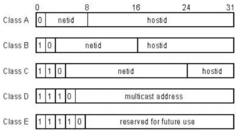
Networks attached to the Internet are assigned class types that determine the maximum number of possible hosts per network. The previous figure illustrates how the net and host portions of the IP address differ among the three classes. Class A is assigned to networks that have more than 65,535 hosts; Class B is for networks that have 256 to 65534 hosts; Class C is for networks with less than 256 hosts.
| IP Network Classes | |||
| Class | Maximum Number of Networks in Class | Network Addresses (Host Portion in Parenthesis) | Maximum Number of Hosts per Network |
| A | 126 | 1(.0.0.0) to 126(.0.0.0) | 16,777,214 |
| B | 16,382 | 128.1(.0.0) to 191.254(.0.0) | 65,534 |
| C | 2,097,150 | 192.0.1(.0) to 223.255.254(.0) | 254 |
Note: All network addresses outside of these ranges (Class D and E) are either reserved or set aside for experimental networks or multicasting.
When an IP address's host portion contains only zero(s), the address identifies a network and not a host. No physical device may be given such an address.
The network portion must start with a value from 1 to 126 or from 128 to 223. Any other value(s) in the network portion may be from 0 to 255, except that in class B the network addresses 128.0.0.0 and 191.255.0.0 are reserved, and in class C the network addresses 192.0.0.0 and 223.255.255.0 are reserved.
The value(s) in the host portion of a physical device's IP address can be in the range of 0 through 255 as long as this portion is not all-0 or all-255. Values outside the range of 0 to 255 can never appear in an IP address (0 to 255 is the full range of integer values that can be expressed with eight bits).
The network portion must be the same for all the IP devices on a discrete physical network (a single Ethernet LAN, for example, or a WAN link). The host portion must be different for each IP device — or, to be more precise, each IP-capable port or interface — connected directly to that network.
The network portion of an IP address will be referred to in this manual as a network number; the host portion will be referred to as a host number.
To connect to the Internet or to any private IP network that uses an Internet-assigned network number, you must obtain a registered IP network number from an Internet-authorized network information center. In many countries you must apply through a government agency, however they can usually be obtained from your Internet Service Provider (ISP).
If your organization's networks are, and will always remain, a closed system with no connection to the Internet or to any other IP network, you can choose your own network numbers as long as they conform to the above rules.
If your networks are isolated from the Internet, e.g. only between your two branch offices, you can assign any IP Addresses to hosts without problems. However, the Internet Assigned Numbers Authority (IANA) has reserved the following three blocks of IP Addresses specifically for private (stub) networks:
| Class | Beginning Address | Ending Address |
| A | 10.0.0.0 | 10.255.255.255 |
| B | 172.16.0.0 | 172.31.255.255 |
| C | 192.168.0.0 | 192.168.255.255 |
It is recommended that you choose private network IP Addresses from the above list. For more information on address assignment, refer to RFC 1597, Address Allocation for Private Internets and RFC 1466, Guidelines for Management of IP Address Space.
Subnet Mask
In the absence of subnetworks, standard TCP/IP addressing may be used by specifying subnet masks as shown below.
| IP Class | Subnet | Mask |
| Class A | 255.0.0 | 0 |
| Class B | 255.255 | 0.0 |
| Class C | 255.255 | 255.0 |
Subnet mask settings other than those listed above add significance to the interpretation of bits in the IP address. The bits of the subnet mask correspond directly to the bits of the IP address. Any bit an a subnet mask that is to correspond to a net ID bit in the IP address must be set to 1.
Appendix C – IP Protocol and Port Numbers
Common Internet service protocols and IP port numbers.
IP Protocol Numbers
| Protocol # | Protocol Name | Description |
| 1 | ICMP | Internet Control Message [RFC792] |
| 2 | IGMP | Internet Group Management [RFC1112] |
| 6 | TCP | Transmission Control [RFC793] |
| 8 | EGP | Exterior Gateway Protocol [RFC888,DLM1] |
| 9 | IGP | any private interior gateway [IANA](used by Cisco for their IGRP) |
| 17 | UDP | User Datagram [RFC768,JBP] |
| 46 | RSVP | Reservation Protocol [Bob Braden] |
| 88 | EIGRP | EIGRP [CISCO,GXS] |
| 115 | L2TP | Layer Two Tunneling Protocol [Aboba] |
IP Port Numbers
| Service | TCP | UDP | Notes |
| FTP | 21 | File Transfer | |
| Telnet | 23 | ||
| SMTP | 25 | Simple Mail Transfer | |
| DNS | 53 | 53 | Domain Name Server |
| Finger | 79 | ||
| WWWHTTP | 80 | World Wide Web HTTP | |
| POP3 | 110 | Post Office Protocol – Version 3 | |
| 137 | 137 | NetBios Name Service | |
| 138 | 138 | NetBios Datagram Service | |
| 139 | 139 | NetBios Session Service | |
| SNMP | 161 | ||
| SNMP Trap | 162 |
Appendix D - Technical Specifications
| General | |
| Ports | |
| Number of Ports:6 Ethernet ports2 Analog phone ports1 Console port | RJ-45RJ-11DB-9 RS-232 DCE |
| LED Readout | |
| Power | |
| Test | |
| ISDN Link, B1, B2 | |
| Ethernet | Col, Link/Act - Uplink, 1,2,3,4,5, |
| Phone 1,2 | |
| LAN | |
| Standard | IEEE 802.3 10BASE-T Ethernet |
| LAN Protocol CSMA/CD | |
| Data Transfer Rates | 10Mbps (half duplex) |
| Network Cables | |
| 10BASE-T:2-pair UTP Cat.3, 4, 5(100m max. length) | EIA/TIA-568 100-ohm screened twisted-pair |
| ISDN | |
| Standard PPP/Multi-linkPPP | |
| ISDN Protocols | |
| ISDN speeds | ISDN BRI: up to 128,000bps |
| ISDN Interface | Standard BRI S/T |
| 1 ISDN BRI port: 64Kbps B channel x 216Kbps D channel x 1 | |
| ISDN network Compatibility | |
| Europe and Asia: SupportsDSS1, EuroISDN and Taiwan | DGT switches, and Siemens EWSD switches |
| Data Compression | Hi/fn? LZS (Stac) |
| Compression Ratio: 4 to 1 | |
| Routing | |
| IP Packet Routing | TCP/IP with RIP-1 and RIP-2, static routes |
| IPX Packet Routing (TW-H6W1IRM) | Novell IPX with RIP, SAP, Spoofing |
| Bridging | |
| Transparent MAC-layerbridging (TW-H6W1IRM) | 802.1d Spanning Tree (TW-H6W1IRM) |
| Other Protocols | UDP, TCP, NAT, DHCP, BAP/BACP, ICMP |
| Management | |
| SNMP | MIB-II |
| Security | PAP, CHAPAdministrative passwordFirewall filteringRADIUS |
| Physical & Environmental | |
| DC Input:External DC power adapter | 18V 750mA unregulated or regulated |
| Power Consumption 8.5W max. | |
| Ventilation Fanless | |
| Operating Temperature | 0 - 50 C (32 - 122 F) |
| Storage Temperature | -25 - 55 C (-13 - 131 F) |
| Humidity | 5% - 95% non-condensing |
| Dimensions | 220mm x 166mm x 45mm(8 3/5" x 6 1/2" x 1 3/4") |
| Emissions (EMI) | FCC Class B, VCCI Class B, CE Mark |
| Safety | UL (UL1950), CSA (CSA950) |
Appendix E – Country ID Numbers
Please refer to the list below for country ID numbers used to configure the ISDN interface of the router.
The router can be configured when performing a Software Update through a configuration file.
The configuration file can hold many settings for the router including IP Addresses for all ports, path to the boot server, and various port settings.
The configuration file is very useful if you wish to update your software and keep all or most of your settings the same.
The configuration file should be saved with the extension .SYS in the same directory as the runtime image file (software update file).
An example configuration file is shown below. Please note that:
: Comment. This line describes the actual configuration in the next line. You can also use this feature to mask items you don't need to be configured (rather than deleting them).
Format: Keyword
ip-stat disable
ip-stat is the keyword as explained in the # (comment) line above it as meaning IP routing statistics.
disable is the parameter you set.
Configuration File Example
<h1 id="the-system-configuration-file-for-trendnet-tw-h6w1ir">The system configuration file for TRENDNET TW-H6W1IR</h1>
ISDN Remote Access Router

<h1 id="tw-h6w1ir-runtime-image-file-name-software-update">TW-H6W1IR runtime image file name (software update</h1>
path and file name)
h6w1r-image
d:\project\twh6w\runtime\image\h6wrun\h6wrun.hdr

<h1 id="sysname-string-name">sysname (string name)</h1>
sysname TW-H6W1IR ISDN Router
<h1 id="syscontact-string-name">syscontact (string name)</h1>
syscontact Engineering Administrator, Pongo
<h1 id="syslocation-string-name">syslocation (string name)</h1>
syslocation Myson Building 6th floor
<h1 id="systimeout-setting-in-minutes-0-means-no-timeout">systimeout setting in minutes (0 means no timeout)</h1>
systimeout 15
<h1 id="telnet-stat-enabledisable">telnet stat (enable/disable)</h1>
telnet disable
<h1 id="discovery-stat-enabledisable">discovery stat (enable/disable)</h1>
discovery enable
<h1 id="ip-routing-stack-enabledisable">ip routing stack (enable/disable)</h1>
ip-routing enable

<h1 id="interface-decription-string-name">interface decription (string name)</h1>
lan-port System 10BaseT Lan Interface
<h1 id="port-stat-enabledisable">port stat (enable/disable)</h1>
port-stat enable
<h1 id="ip-address">ip address</h1>
ip-address 202.39.74.115
<h1 id="subnet-mask-2">subnet mask</h1>
ip-netmask 255.255.255.0
<h1 id="routing-protocol-type-0ripv1-1ripv2-2ripv12">routing protocol type (0:RIPv1, 1:RIPv2, 2:RIPv1&2)</h1>
routing-type 2
<h1 id="routing-operating-mode-0none-1listen-2talk-3both">routing operating mode (0:None, 1:Listen, 2:Talk, 3:Both)</h1>
operating-mode 1
<h1 id="ip-routing-stat-enabledisable">ip routing stat (enable/disable)</h1>
ip-stat enable

<h1 id="interface-description-string-name">interface description (string name)</h1>
isdn-port ISDN DSS1 Interface
<h1 id="interface-switch-type-0dss1">interface switch type (0:DSS1)</h1>
switch-type 0
<h1 id="interface-country-code-0-255">interface country code (0-255)</h1>
country-code 0
<h1 id="b-channel-usage-0none-1leased-2switch">B channel usage (0:None, 1:Leased, 2:Switch)</h1>
b1-usage 2
b2-usage 2
<h1 id="isdn-data-call-phone-number-string">ISDN data call phone number string</h1>
isdn-data 5779110-6403
<h1 id="ab-adapter-phone-number-string">AB adapter phone number string</h1>
ab1-adapter 8358661
ab2-adapter 8358662
<h1 id="voice-call-waiting-state-enabledisable">voice call waiting state (enable/disable)</h1>
call-waiting disable
<h1 id="voice-call-routing-state-0none-1ab1-2ab2">voice call routing state (0:None, 1:AB1, 2:AB2)</h1>
call-routing 0
<h1 id="voice-call-global-reception-state-enabledisable">voice call global reception state (enable/disable)</h1>
global-recept disable
<h1 id="block-clid-state-enabledisable">block CLID state (enable/disable)</h1>
block-clid disable
<h1 id="port-stat-enabledisable-2">port stat (enable/disable)</h1>
port-stat enable
<h1 id="ip-address-2">ip address</h1>
ip-address 20.19.88.1
<h1 id="subnet-mask-3">subnet mask</h1>
ip-netmask 255.255.255.0
<h1 id="routing-protocol-type-0ripv1-1ripv2-2ripv12-2">routing protocol type (0:RIPv1, 1:RIPv2, 2:RIPv1&2)</h1>
routing-type 1
# routing operating mode (0:None, 1:Listen, 2:Talk, 3:Both) operating-mode 2
ip routing stat (enable/disable)
ip-stat disable
Index
A
A/B Adapter.... 1
Access Right 44
Admin[istration] Configuration..105
Advanced Functions....47
Age 108
ARP request....50
Auth Type 49
automatic timeout....27
B
B (Bearer) channels 47
Bandwidth Allocation Control Protocol....3
Bandwidth Allocation Protocol.....3
Bandwidth on Demand......47
Bandwidth On Demand ..... See BOD
BAPSee Bandwidth Allocation Protocol
B-channel....49,50
BOD....3
Boot File Name 129
Boot Protocol....128
Boot Server IP Address ...... 128
BootP&TFTP 128
Bridging....1,3
C
Caller ID....56, 59
Challenge Handshake Authentication Protocol See CHAP
CHAP....4,34
Code 114
Configuration 26
Configuration File 147
Configuration File Example......148
Connection Test....116
connections......48
Console 15, 16
Console program....26
Console Program....16, 27
Counter......109
CUSeeMe....83
D
D channel....47
Data 116
default gateway 55
default login 26
default next hop router......50
DHCP....61
Diablo 83
Diagnostic 116
Diagnostic port 15, 16
Dial on Demand 51, 54
Dial On Demand....3
dial-in....47,55
dial-in network connection ..... 49
Dial-In User Connections...... 48
Dial-in User Profile 98
Dial-In User Profile 48,52
Dial-in users 48
dial-out connections 47
Dial-Out Network Connections....50
Direction 58
DNS 95
DNS Cache State 96
DNS Configuration....95
DNS Domain Name......96
DNS IP 63
Domain Name 63
Dynamic Host Configuration Protocol....4
Dynamic IP Pool 62
Dynamic NAPT....83, 89
Dynamic NAT......88
E
EEPROM 26
Event/Error Log 113
Execute Bootload ...... 129, 130
F
Factory Reset...... 122, 130
fax calls 47
Filter Configuration ......65
Filter State of Interface......67
filters 84
firewall 76, 79
Flash memory 26
Forward DNS queries to......95, 96
Forwarding (LAN)......37
Front panel LED's....11
FTP servers....91
G
Gateway....41, 63
Gateway address....50
Gateway IP address....78
Global Interface......86
global IP address 76
H
Hops 41
Host Name 97
I
ICMP 72
Idle Time 54
IGMP 39
image file 127
impostor....74
Initial Configuration....21, 27
Interface 50, 58
Interface Configuration......30, 48
Internet....5, 50, 80
IP Address......36, 45, 75, 126
IP Address Supply 57
IP Addresses 139
IP Concepts ...... 139
IP Filter....67, 70
IP Multicasting....38
IP Network Classes 140
IP Networking 42
IP Port Numbers....83, 143
IP Protocol....143
IP Protocol Numbers 143
IP STACK 37
IP Stack Configuration...... 35
IP Static Route 40
IP Static Route Table 41
IP Static Routes 50
IPX....3
ISDN....11,32,35
ISDN Counter Table...... 111
ISDN Interface 50
ISDN L1....58
ISDN line....47
ISDN submenu......48
ISP....50
K
Key....98,134
L
Lan....3
LAN..3,5,6,7,10,31,35,43,73,137
LAN Counter Table.... 109
LAN Port....22
Layer 2 Filter 67, 68
Lease Time....63
Listen....38
Local Area Network ...... See LAN
Local Interface 86
local IP address....76
Log and Trace.... 113
Lookup Host Table....96
M
MAC address....50
MAC Address 64,75
Main Menu....27
Management......26
Mask....69
Menus
1 (General Setup)......28
Main 27
Microsoft NetMeeting......83, 87
MIP 72
MLPPP....99
Multicast Protocol ......39
Multi-Link PPP 99
Multiple Home Configuration......72
N
NAPT....76
Dynamic NAPT 87
Static NAPT....87
NAT....76
Dynamic NAT......87
Static NAT......87
NAT Configuration 76
NAT IP Pool......86, 88, 89, 90, 91
Netmask....36, 62
Network Configuration 35
next hop router....51
o
Offset......69
Operation....72
P
PAP....4,34
Password......48
Password Authentication ProtocolSee PAP
physical port......49
Ping Test....118
Plain Old Telephone ServiceSee POTS
Point-to-Point Protocol/Multilink
Protocol.....See PPP/MP
Port....91, 98, 115, 134
port numbers 83
Port Numbers 143
Interface....116
POST 26,124
POTS 1
PPP Configuration....99
PPP/MP 3
private network....76
private networks 84
PROM System Configuration.....124
PROM System Menu....124
Protocol Type....71
R
Radius 97
Radius Configuration....97
Radius server....55, 97
Range....53,62
Rem CLID 56
Remote Access....51
Remote Access Configuration.....47
remote connections......47
Remote Dial-in Users 1,5
Remote Network Connections.....49
Remote Network Profile......49, 50
Remote Network Profiles ...... 48
Remote networks 49
Remote Node....1,3
Remote Operation Overview......48
Retry Count 54
Retry Time 54
RouteMan.... 121, 127
Router Configuration Utility22, 121, 127
Routing Mode 38
Routing Protocol....37
routing table 50
Routing Table....107
RS-232....3, 15, 20, 131, 136
S
SAVE....129
security....76, 79, 84
Send BootP request....126
Set Peer IP as Default Gateway...54
Simple Network Management Protocol......See SNMP
single user account 82
Single User Account....1, 5
SMT....136
SNMP....3,43
SNMP Agent Configuration......43
SNMP Authenticated Trap......46
SNMP Community 44
SNMP Community String .....44, 45
SNMP Trap Manager......45
Software Update ...... 121, 127
Software Update Control ..... 128, 129
Static ARP....74
Static ARPs....50
Static IP Pool....63
static NAPT....80
Static NAPT....83, 91
static NAT....80
Static NAT....90 50
Statistics....107
stub network....81
SUA ......See Single User Account
Subnet Mask....141
System Contact....28
System Description ......28
System Information ......28
System ISDN Test....120
System LAN Test....119
System Location......28
System MAC Address....29
System Maintenance .... 106
System Name 28
System Object ID 28
System Reset...... 127, 129
System Restart 121, 122
System Status 106
System Up Time 28
T
Talk 38
TCP/IP....1,3,5
TCP/IP Parameters Configuration126
Telecommuting 5
telephone jacks 47
telephone number....50
Telnet ...... 3, 9, 15, 27, 42, 131, 132
Using Telnet via ISDN...... 132
Using Telnet via LAN...... 131
Telnet Configuration.... 131
Telnet Enable 94
TFTP 128
TFTP server....121, 127
Time....115
Timeout....29
Trace Buffer....115
Translation Mode 87
Transparent Bridging .. See Bridging
U
UNNUMBER 37
Update Software from
Configuration File......129
User Profile 55
Username 48
V
virtual circuit......49, 58
visible computer....87
voice 47
W
14
web server....80
WINS IP....63