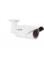
OB-300NE STAR - Security Camera Brickcom - Free user manual and instructions
Find the device manual for free OB-300NE STAR Brickcom in PDF.


| Product Type | Network Security Camera |
| Model | OB-300NE STAR |
| Brand | Brickcom |
| Resolution | Up to 1920x1080 (Full HD) |
| Video Compression | H.264, MPEG-4, MJPEG |
| Frame Rate | Up to 30 fps at 1080p |
| Lens | Vari-focal (manual) with FocusEasy™ |
| Night Vision | IR cut filter, IR LEDs (intensity adjustable) |
| Audio | Built-in microphone and speaker, two-way audio |
| Network Interface | 10/100 Ethernet, IEEE 802.1X, PoE |
| Wireless | Optional (WCB/WOB/WMB models only) |
| Storage | MicroSD/SDHC/SDXC card slot (local), NAS, FTP, Samba |
| Power Supply | PoE (802.3af) or 12V DC |
| Power Consumption | < 12W |
| Dimensions (W x H x D) | Approx. 70 x 60 x 50 mm |
| Weight | Approx. 300 g |
| Operating Temperature | -10°C to 50°C |
| Humidity | Up to 90% non-condensing |
| Mounting | Ceiling, wall, or table mount |
| Security | IP filter, HTTPS, OpenVPN, user management |
| Video Analytics | Motion detection, intrusion, tampering, people counting |
| Protocols | TCP/IP, UDP, HTTP, HTTPS, RTSP, RTCP, DDNS, UPnP, EasyLink™, ONVIF |
| Compliance | ONVIF Profile S |
Frequently Asked Questions - OB-300NE STAR Brickcom
User questions about OB-300NE STAR Brickcom
0 question about this device. Answer the ones you know or ask your own.
Ask a new question about this device
Download the instructions for your Security Camera in PDF format for free! Find your manual OB-300NE STAR - Brickcom and take your electronic device back in hand. On this page are published all the documents necessary for the use of your device. OB-300NE STAR by Brickcom.
USER MANUAL OB-300NE STAR Brickcom
Brickcom Software User's Manual
For Firmware Release V3.7.0.xx
Product name: Network Camera v3.7.0.xx
Firmware
Release Date: 2016/04
Manual Revision: V6.0.
Web site: www.brickcom.com
Email: support@brickcom.com
info@brickcom.com
© 2016 Brickcom Corporation. All Rights Reserved
| High Resolution & Performance Series | Universal Series | Budgetary Series | Elite Series | |
| Camera/Vedio/Audio | ||||
| Camera | ● | ● | ● | ● |
| video | ● | ● | ● | ● |
| Audio (*) | ●(Built - in Mic) | ●(Built - in Mic) | ||
| FocusEasy (*) | ●All (VariFocal Lens) | |||
| Multicast | ● | ● | ● | ● |
| Privacy Mask Control | ● | ● | ● | ● |
| Camera Control * | ||||
| Preset Point | ● | |||
| Patrol Settings | ● | |||
| PTZ Configuration | ● | |||
| Network | ||||
| Network Settings | ● | ● | ● | ● |
| UPnP | ● | ● | ● | ● |
| DDNS | ● | ● | ● | ● |
| EasyLinkTM | ● | ● | ● | ● |
| Wireless(*)Unique Series | ||||
| HTTP/HTTPS | ● | ● | ● | ● |
| OpenVPN | ● | ● | ● | ● |
| Event | ||||
| Event Settings | ● | ● | ● | ● |
| Motion Detection | ● | ● | ● | ● |
| Intelligent Video Analysis | ● | ● | ● | |
| Digital Input | ● | ● | ● | |
| Audio Detection | ● | ● | ● | |
| Temperature | ● | ● | ● | |
| PIR(*) Professional CB Series | ||||
| Notification | ||||
| FTP Settings | ● | ● | ● | |
| E-mail Settings | ● | ● | ● | ● |
| Samba Settings | ● | ● | ● | |
| HTTP Settings | ● | ● | ● | |
| Digital Output (DO) | ● | ●(Except for MD Series) | ● | |
| Video Clip / Snapshot | ● | ● | ● | ● |
| Audio Clip (*) | ●(Built - in Mic) | ●(Built - in Mic) | ||
| System | ||||
| System Log | ● | ● | ● | ● |
| Date and Time | ● | ● | ● | ● |
| Device Information | ● | ● | ● | ● |
| Storage Management | ● | ● | ● | |
| LED Indicators | ● | ● | ● | |
| VMS Compatibility | ● | ● | ● | ● |
| Maintenance | ||||
| User Management | ● | ● | ● | ● |
| Language | ● | ● | ● | ● |
| IP Filter | ● | ● | ● | |
| Firmware Upgrade | ● | ● | ● | ● |
| Configuration | ● | ● | ● | ● |
| Reset to Default | ● | ● | ● | ● |
| Reboot | ● | ● | ● | ● |
Table of Contents
Log in the Camera 4
Installing the Plug-In ....4
Live View 6
Configuration 13
Camera/Video/Audio 13
Camera — Scene Selector .... 13
Camera — Profile 19
Video 23
Audio 28
FocusEasy (*) 30
Multicast....30
ROI (Region of Interest) 31
Privacy Mask Control 32
Camera Control 32
Preset Point 32
Patrol Settings 34
PTZ Configuration 35
Network 35
Network Settings 35
UPnP 38
DDNS (dynamic domain name service) 38
EasyLink™ 40
Wireless....41
LTE/3G 47
HTTP/HTTPS 48
OpenVPN 50
Event....52
Event Settings....52
Motion Detection....56
Intelligent Video Analysis ( IVA ) 58
Digital Input....64
Audio Detection....64
Temperature Detection 65
PIR (Professional Cube Only) 65
Notifications....66
FTP Settings 66
Brickcom
E-mail Settings....66
Samba Settings 67
HTTP Settings 67
Digital Output (DO) 68
Video Clip/Snapshot 68
Audio Clip....70
System....71
System Log 71
Date and Time 72
Device Information 74
Storage Management....75
LED Indicators 77
VMS Compatibility....77
Maintenance....77
User Management....77
Language 78
IP Filter 79
Firmware Upgrade 79
Configuration 80
Reset to Default....80
Reboot....81
Log in the Camera
To access the camera's live view, open a web browser and enter the IP address of the camera. The log-in window will pop requesting a username and password. As stated on the previous page, for the default username and password are "admin" and "admin". For accounts other than the administrator's account, the user can choose to remember the password for future convenience. It is not recommended to check this box when viewing the camera feed from a public computer.

Installing the Plug-In
For the initial access to the camera in Windows, the web browser may prompt the administrator for permission to install the plug-in for Internet Explorer. Permission request depends on the Internet security settings of the user's PC or notebook. If the highest security level is set, the computer may prohibit any installation and execution attempt. This plug-in has been registered for certificate and is used to display the video in the browser. Click to proceed. If the web browser does not allow the
administrator to continue the installation, check the Internet security option and lower the security levels or contact the networking supervisor or IT for help.

NOTE – If an error occurred or the plug-in fails to install, it is because the version of the Electronic Signature is newly released and the VeriSign has not been submitted to Microsoft Windows update for validation. Therefore, plug-in will not have its root certificate. If IE discovers that there is no root certificate after the user's PC connects to the camera, it will automatically redirect to VeriSign Web site to download and install the latest root certificate to make the installation successfully. If the user's computer is able to connect to camera but unable to access the internet, then the installation will fail since the computer will not be able to download the latest root certificate. This problem can be resolved if computer can be connect to the internet and the camera at the same time and will not recur when Windows update patches become available.
Live View
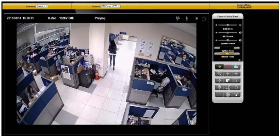
NOTE - (*) These are optional features. Please refer to the Product List for the full list of optional features available for the product.
Live View is the default page that opened when accessing the camera. Live video is displayed directly in the browser window.
- Channels
The network camera offers simultaneous multiple streams. This drop-down list allows the user to switch between different video channels. For further detail, please go to
- Protocol
RTSP over HTTP – This unicast method can be used to traverse firewalls. Firewalls are commonly configured to allow the HTTP protocol, thus allowing RTP to be tunneled.
TCP - This protocol guarantees the complete delivery of streaming data and provides better video quality. The downside of using this protocol is that the quality of its real-time effect is less than that of the UDP protocol.
UDP - This protocol allows for more real-time audio and video streams. However, network packets may be lost due to network burst traffic and images may be broken. Activate UDP connection time-sensitive responses are more important than video quality.
● LED Control (CB-series Professional only)
Use the drop-down menu to adjust the brightness of the camera's LED.
● Image Dewarping (MD-500Ap-360P, MD-300Np-360P, and CB-500Ap-360P Only)
The image dewarping function is only provided for these cameras on the Live View page with the Internet Explorer.
Camera Position: Ceiling, Ground, Wall
The Camera Position list box offers 3 modes which reflect where the camera is installed: Ceiling, Ground, and Wall. Please make sure you select the correct Camera Position for the best user experience.
Ceiling – When the camera is fixed on the ceiling, or is installed to shoot in the top-down direction, please choose this mode.

Ground – When the camera is fixed on the ground or table, or is installed to shoot in the bottom-up direction, please choose this mode.
Brickcom

Wall – When the camera is fixed on the wall, or is installed to shoot in the horizontal direction, please choose this mode.
- Panorama: OFF, PTZ, Quad, Perimeter

The Panorama list box offers 4 display modes: OFF, PTZ, Quad, and Perimeter. Please select the display mode that best meets your needs.
OFF - This is the default display mode, and shows the original elliptical image of the camera.

PTZ – This display mode can operate the pan, tilt, and zoom functions via the mouse. Drag the mouse when you want to view in different directions. Scroll the mouse wheel when you want to zoom in and zoom out the view. PTZ is typically used when the camera is installed on the ceiling or ground.

Quad – This display mode shows four separate PTZ windows. Each window can operate the pan, tilt, and zoom functions. Quad is typically used when the camera is installed on the ceiling or ground.
Brickcom
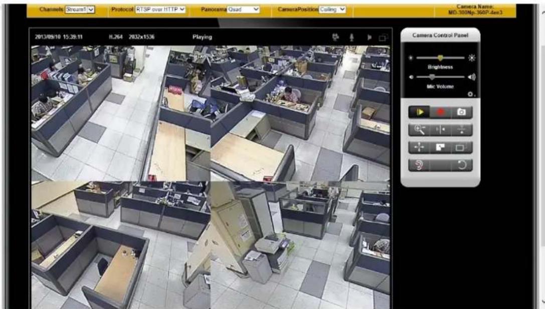
Perimeter – This display mode can dewarp the elliptical image and show the 180-degree view. Perimeter is typically used when the camera is installed on the wall.

Status Icons


cording on/off - Displays the status of recording video


C on/off - Displays the status of the MIC volume


Speaker on/off - Displays the status of the Speaker


) on/off - Displays the status of Motion Detection
Brickcom
● Brightness - Drag the slider bar to adjust the image brightness level.
● Mic volume - Drag the slider bar to adjust the microphone volume.
- Speaker volume - The built-in speaker will play sound from an audio clip from the computer microphone when it is enabled.
For more Audio settings, please refer to the Audio configuration page.

Play or Stop - Play or stop the video.
Recording - Record video to a computer.

Snapshot - Capture and save still images.
Digital Zoom - Enable the digital zoom operation.

Mirror - Horizontally reflect the display of the live video.

Flip - Vertically reflect the display of the live video.

Real Size - View the object in real size. Press it again to switch back to node.

Full Screen - Switch to full screen mode. Press the "Esc" key to return to mode.

Motion Detection Alert - Enable the motion detection alert function. (Please Motion Detection on P.49)
Mute – Turn off the sound.
Talk (*) – To send the voice from the user side to the camera

Set Default – Reset to default settings.
PTZ Control (OSD series and PZ-040 series only)
NOTE - Commanding the OSD to do Pan-tilt too frequent (by following ways) within 1\~3 seconds might result in "Submit failed" error message with abnormal pan-tilt behavior.

Patrol - Enable the patrol function. If a designated patrol has not been set for that time period, the first patrol group on the patrol list will be enabled.
Pan/Tilt Control - Click on the arrows to pan and tilt the camera. Click the center of icon to return to the home position.

Joystick Mode – Scroll over the live view window to move the camera view in the direction of the mouse pointer.

Center Mode - Click on a point in the live view window to center the camera view on that point.

Edit the live view snapshot and video clip saved file folders.

Recording folder path: Click [Browse] to specify the full path of the folder for saving the recorded video files.
Snapshot folder path: Select the format from the drop-down menu. Click [Browse] to specify the full path of the folder for saving the snapshot files.

NOTE The
Configuration
Click

NOTE - Only Administrators can access the Configuration page.
Camera/Video/Audio
Camera — Scene Selector (For all camera except for OSD Series, OB-LR Series and MD-300Np-360 star)

Scene List
Smart Auto - Camera controls itself fully automatically
- Indoor 60Hz - Indoor, lighting 24 hours a day, power frequency 60Hz
- Indoor 50Hz - Indoor, lighting 24 hours a day, power frequency 50Hz
Outdoor - Outdoor, lighting condition changes by nature
✿ Car License Plate - Optimized view modes for capturing the moving car license plate clearly. Additional lighting may be necessary.
✿ Schedule - A pre-defined weekly schedule determines when camera shall switch to which view mode.
Digital Input - An external device triggers the camera to Day mode or Night mode, via the camera's Digital Input.
✿ Entrances/Elevators - Optimized view modes for the entrances or areas which may have strong backlight, such as the main gates, elevators, etc.
Always – Full time.
Click [Activate] button to activate or click [Edit] for detailed settings.
Reset to default : Reset the Scene mode to the original default settings.
Export Setting / Import Setting: User can export the camera settings to a configure file, and import the settings to other cameras
Scene Setting - Indoor 60Hz / Indoor 50Hz / Outdoor / Car License Plate

Brickcom
After user select the
Scene Name: Depends on the user activate preferred scene mode
Scene Description: Detail description about the Scene.
Day Profile : Click the button for further [Day Profile] setting.(Please refer to P.17)
Night Profile : Click the button for further [Night Profile] setting. (Please refer to P.17)
Profile Management: User can set up preferred detected value and lasting second according to the lighting environments.

User can adjust the detected values for Day & Night profile switching. Red line shows "Current detected value", Orange-yellowed line shows "Day Profile detected value" and blue line shows "Night Profile detected value".
Scene Setting-Schedule

Brickcom
After user select the
Schedule – Select Schedule to schedule specific time periods for different profiles.
Click the button for further [Profile X] setting.(Please refer to P.17)
Scene Setting - Digital Input
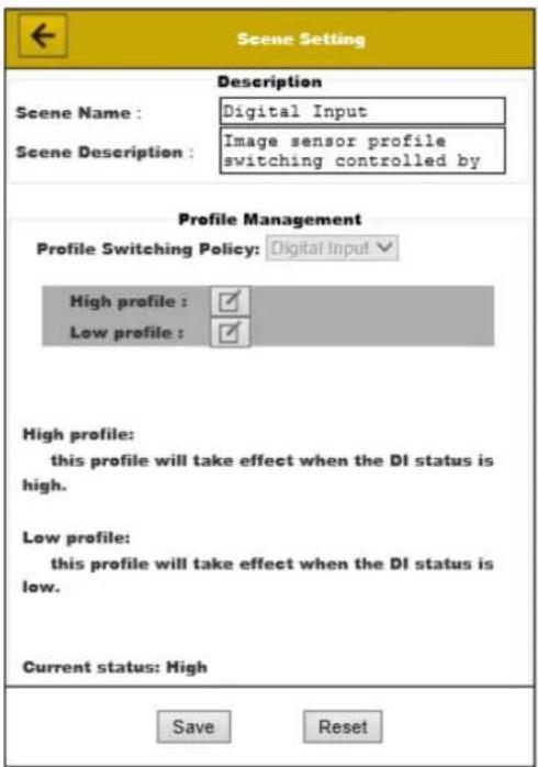
Digital Inputs (*) (Only available for models with the Digital Input interface) - Select Digital Input to have the profile management controlled by an external sensor. Click the
button for further High/Low profile setting. (Please refer to P.17)
Scene Setting – Entrances / Elevators

Entrances / Elevators - click the button for further profile setting (Please refer to P.17)
Profile Setting
In [Scene Setting] window, user can click the button for further profile setting as below:


Brickcom
◆ Brightness - Drag the bar to adjust the image brightness level.
- Contrast - Drag the bar to adjust the image contrast level.
◆ Sharpness - Drag the bar to adjust the image sharpness level.
✿ Saturation - Drag the bar to adjust the image saturation level.
Exposure Control
User can adjust the value of Dynamic Shutter and Dynamic Gain for the best user experience or simply choose Fixed Shutter and Fixed Gain.
✿ Shutter Speed - User can choose
Gain - User can choose
✿ Metering Option - Center-weighted average metering.
❖ Flicker-Free - Eliminates the problem of flicker.
✿ EV Compensation - Drag the bar to adjust the EV (exposure value) compensation level.
✿ AE Speed - Automatically control exposure speed from 1 to 3.
High Light Suppression – Highlight Suppression cuts off strong lighting such as a car's headlights. According to user's requirement, user can
De-Noise - De-Noise can be set to auto, or between 1 and 10, with 10 giving the best de-noise effect.
✿ IR Cut (*) (Only available for models with the IR Cut) - Deactivate or activate the IR cut filter
Color Effect - Select to display color or black and white video streams.
- White Balance - White Balance can be simply set to auto, or enter the desired level in
✿ WDR (*) - Check "Enable" to see things clearly even if the objects are in strong backlight.
Click [Save] to save the changes or click [Reset] to back to the original settings.
Camera — Multi Profile (For OSD 200Np 30x, OB-LR Series and MD-300Np-360 star)

Profile – Up to five profiles can be used for different lighting environments. Day and night are default profiles and users can create additional profiles. Select a profile from the drop-down menu or select different icons to change profile settings.
Name – Name of the Profile
◆ Brightness - Drag the bar to adjust the image brightness level.
✿ Contrast - Drag the bar to adjust the image contrast level.
◆ Sharpness - Drag the bar to adjust the image sharpness level.
✿ Saturation - Drag the bar to adjust the image saturation level.
- Exposure Control – Five presets are available (General, Indoor, Car Plate, Extremely Low Light, and Shutter Priority) for users to select for different situations. Users can adjust the value of Dynamic Shutter and Dynamic Gain for the best user
experience or simply choose Fixed Shutter and Fixed Gain.
✿ Metering Option – Center-weighted average metering.
❖ Flicker-Free – Eliminates the problem of flicker.
✿ EV Compensation –Drag the bar to adjust the EV (exposure value) compensation level.
✿ AE Speed – Automatically control exposure speed from 1 to 3.
- Auto Iris – Enable this function if the auto iris lens is used with camera.
De-Noise – De-Noise can be set to auto, or between 1 and 10, with 10 giving the best de-noise effect.
Mirror and Flip
Mirror - Enable to horizontally reflect the display of the live video.
Flip - Enable to vertically reflect the display of the live video.
✿ IR Cut (*) (Only available for models with the IR Cut) - Deactivate or activate the IR cut filter
✿ IR LED (*) (Only available for models with the IR LED) – Enable to turn on the IR LED. The intensity of the IR can be fixed to a certain level from 1 to 10, or Auto.
Color Effect
Color: Select to display color or black and white video streams.
White Balance: White balance is a camera setting that adjusts for lighting in order to make Black & white. White Balance can be simply set to auto, or select the desired level from the drop-down menu.
✿ WDR (*): Check "Enable" to see things clearly even if the objects are in strong backlight.
Test in Full Screen: Click to access full screen mode.
Click [Apply] to apply settings or [Cancel] to cancel changes.
Profile Management: Profiles can be scheduled to change at scheduled times or under different lightening changes.

Always- Select Always to use a single profile. Select the profile from the drop down menu.
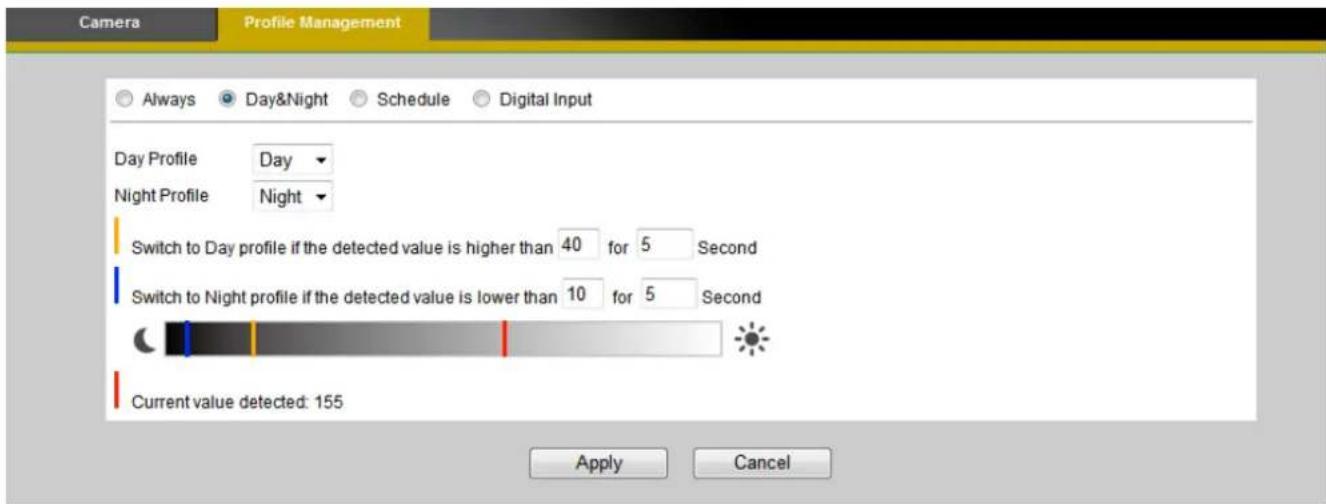
Day & Night (*) (Only available for models with the light sensor) - Select Day & Night to schedule two profiles for day and night. Select profiles from the drop down menu for the Day and Night Profiles.
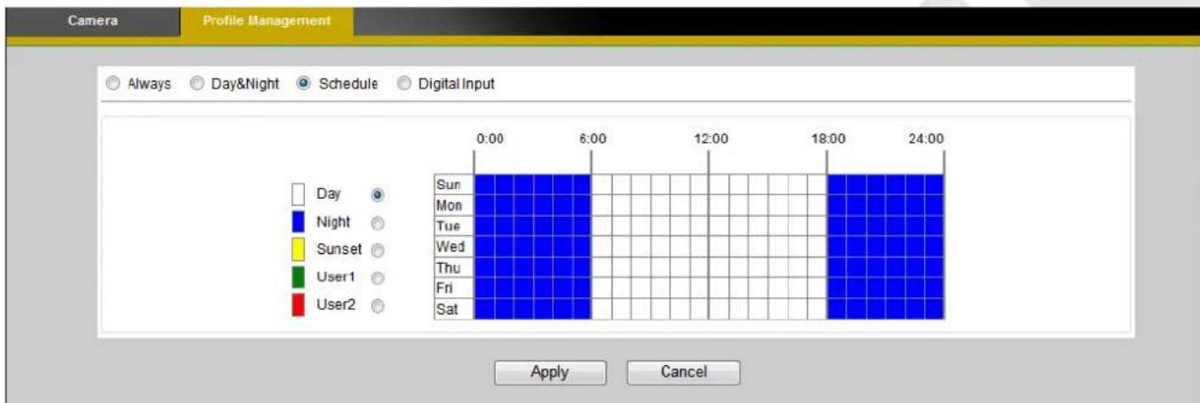
Schedule – Select Schedule to schedule specific time periods for different profiles.

Digital Inputs (*) (Only available for models with the DI interface) - Select Digital Input to have the profile management controlled by an external sensor. Select profiles from the drop down menu. Profiles will be changed depending on the status of DI (Digital Input). Click Apply to apply settings or Cancel to cancel changes.
Video
The Network Camera offers multiple streams for different viewing options.

◆ Display: orientation: Mirror / Flip
Mirror - Enable to horizontally reflect the display of the live video.
Flip - Enable to vertically reflect the display of the live video.
For each stream, the following settings are available:
Video Codec - The Network Camera offers three choices of video codec standards for real-time viewing: H.264, MPEG-4 and MJPEG.
✿ Video Resolution - Select from the drop-down menu to choose the best resolution recording settings.
Frame Rate - Select the frame rate from the drop-down menu. Set a higher frame rate for the smoother video.
Bitrate Mode – Select the bitrate mode from the dropdown menu.
Select Variable Bitrate to manually configure the video quality.
Select Constant Bitrate to manually configure the bitrate.
Set the higher bitrate/ quality for the better video.
Max Bitrate – Enter the value between 64\~12000 Kbps.
Brickcom EVBR
In order to improve VBR encoding capability, Brickcom latest EVBR technology provides better encoding capability with predictable bandwidth consumption. The camera default
Brickcom
will set up the limitation of the bandwidth which can guarantee that the maximum bandwidth can meet the high resolution image quality requirement but not exceed the preset limit. Therefore, user is able to manage both the bandwidth and surveillance system quality effectively than before.
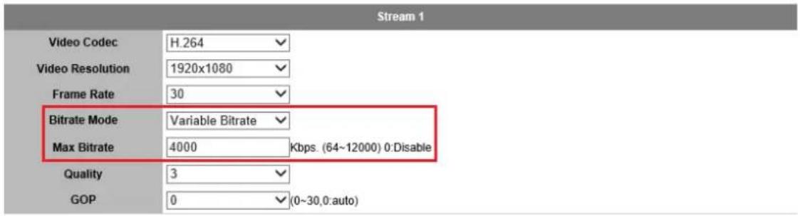
Quality – Select MJPEG video codec to configure the video streaming using Quality. The video quality can be set between Level 1 to Level 6, with Level 6 producing the best image quality.
✿ GOP – Set a higher GOP (group of picture) value for the smoother video transmission on the network. Select 0 to have the camera produce one i-frame per second regardless of the frame rate.
NOTE - A higher bitrate will use higher network bandwidth.
NOTE – HTTP Transport is for non-IE browser used only.
Click [Apply] to apply settings or [Cancel] to cancel changes.
i-Stream
i-Stream technology aims to reduce the bandwidth consumption when transmitting data but still keep the important details for the user. The experiments show that i-Stream can save at least 30% of bandwidth in various scenarios.
Check "Enable" for further i-stream detail settings
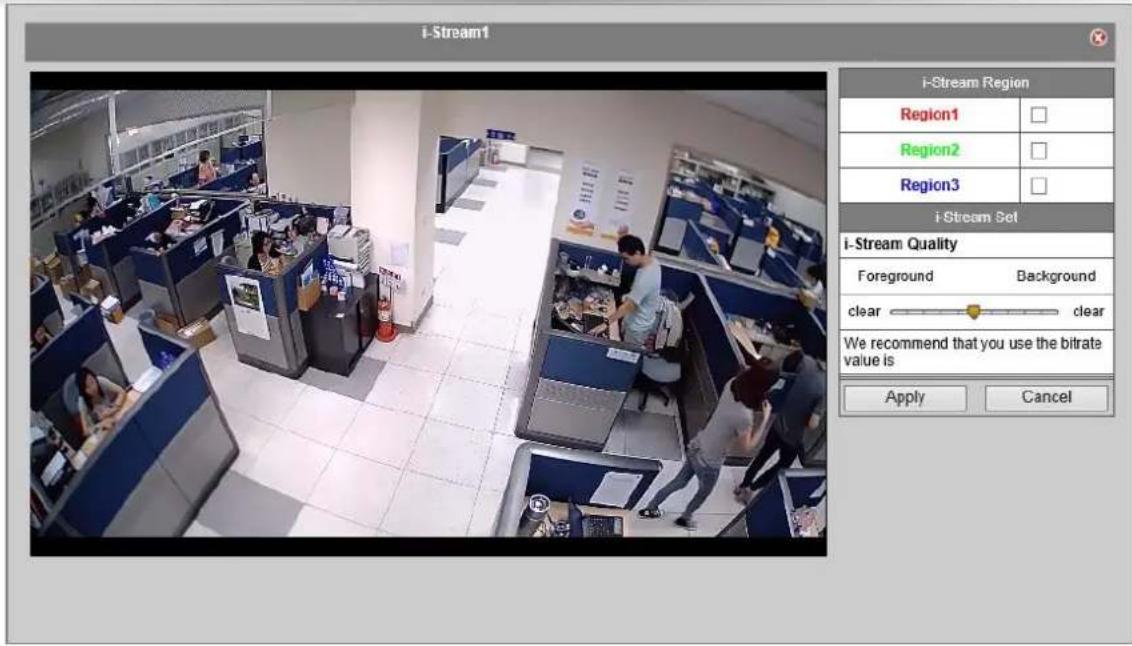
- Check Region item and resize the window.
- Drag the bar to adjust i-stream quality.
- Click [Apply] to apply settings or [Cancel] to cancel changes.
Video Overlay

Timestamp
To display the date and time on the screen during live view, check "Enable" to enable the timestamp function and select the display position from the drop-down menu.
Text
To make a note about the camera, check "Enable" and select the display position from the drop-down menu. Enter a video description in the text box.
Click [Apply] to apply settings or [Cancel] to cancel changes.

NOTE – For the 1 megapixel models, the video overlay will only takes effect on
stream 1.
RTSP Server
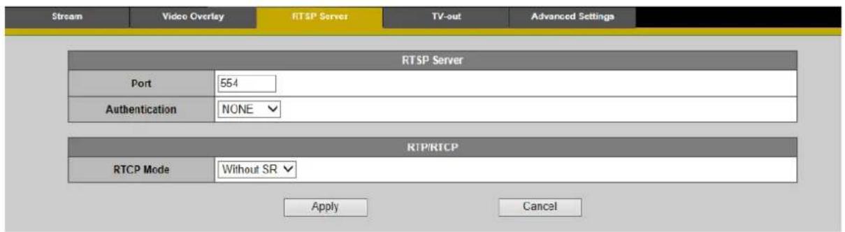
To utilize RTSP authentication, the user must first set a password for the camera. RTSP (Real-Time Streaming Protocol) controls the delivery of streaming media. By default the port number is set to 554.
Authentication - Depending on the network security requirements, the camera provides two types of security settings for streaming via RTSP protocol: NONE, BASIC and DIGEST.
If DIGEST authentication is selected, user credentials are encrypted using MD5 algorithm, thus providing better protection against unauthorized access.
RTP/RTCP
RTCP without SR - RTCP without SR (Sender Report) is the default option. Under this option, audio and video received from the IP camera are played immediately and independent of each other.
RTCP with SR - RTCP with SR option allows synchronization between video and audio on live viewing. Choose this option if audio and video become unsynchronized.
Click [Apply] to apply settings or [Cancel] to cancel changes.
TV Out

Enable the TV-out option. Use dropdown list to choose Standard option (Hardware control/ NTSC/PAL). Click [Apply] to apply settings or [Cancel] to cancel changes.
Advanced Setting

The setting mainly addresses the compatibility issues, and the default setting works fine in most cases. Click [Apply] to apply settings or [Cancel] to cancel changes.
Audio
The administrator can set up multiple separate streams for the camera for different viewing devices. The administrator can enable or disable the audio function for each stream. If audio is enabled, select the desirable audio codec from the drop-down menu. Click [Apply] to apply new settings or [Cancel] to cancel changes.
Brickcom

Advanced Settings
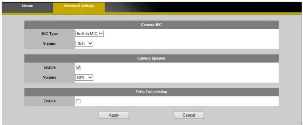
The Network Camera supports two-way audio communication so that operators can transmit and receive audio simultaneously and communicate with people over there.
Camera MIC - Select the desirable type of camera microphone and adjust the volume for the user applications.
Camera Speaker - Check
Echo Cancellation - Check
Click [Apply] to apply settings or [Cancel] to cancel changes
FocusEasy (*)
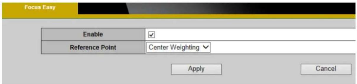
FocusEasy™ is Brickcom's patented technology that makes focusing the camera easy and fast without the help of a monitor. This function is available for the V5 professional manual vari-focal cameras, including the FB-300Np V5, OB-502Ap V5, OB-302Np V5, VD-502Ap V5, VD-302Np V5, etc. This function can be enabled or disabled. When this function is enabled, the user can select either Full Screen or Center Weighting to meet the needs.

NOTE – For the FocusEasy™ supported models, please release the push button
immediately after hearing the activation/de-activation sound.
Click [Apply] to apply new settings or [Cancel] to cancel changes.
Multicast

Multicast sends a video stream to the multicast group address and allows multiple clients to acquire the stream at the same time by requesting the video stream from the multicast group address. Therefore, multicast can effectively save Internet bandwidth.
The RTSP (Real-Time Streaming Protocol) controls the delivery of streaming media.
Click [Enable] to enable the stream needed. Use different port numbers for different
Brickcom
streams. It is recommended to use the default values. Click [Apply] to apply settings or [Cancel] to cancel changes.

NOTE - Using the IP address of the Network Camera enables access to the video.
Example: rtsp://192.168.1.1/channel1
ROI (Region of Interest)
User is able to make the most of its storage capacity, meanwhile keep the important details on specific regions of interest.

a. Enable the window. Adjust the window size.
b. Click [Apply] to apply settings or [Cancel] to cancel changes.
Privacy Mask Control
The camera supports the privacy mask function, which allows user to mask the camera's live view. The user can cover certain areas on the camera image with black to keep privacy in specific circumstances.

Privacy Mask Control –Region Settings allows the user to select specific area(s) to eliminate from the live view and recording to meet the particular needs. Click [Apply] to apply settings or [Cancel] to cancel changes.
Camera Control
(User who use IE11 Brower need to access to the tool menu, then select the compatibility view settings item in the drop-down menu to enable the camera control functions.)
Preset Point

NOTE – Commanding the OSD to do Pan-tilt too frequent (by following ways) within 1\~3 seconds might result in “Submit failed” error message with abnormal pan-tilt behavior.

A preset position is a pre-defined camera view that can be used to quickly move the camera view to a specific location. To create a preset position:
a. Use the Pan, Tilt and Zoom (PTZ) controls to steer the camera view to the required position.
b. Enter a descriptive name under Current Position and click [Add].
c. The camera position and focus settings will be saved as a preset position.

NOTE - A total of sixteen preset points can be set.
d. Preset Positions can be assumed at any time by selecting the preset position's name from the available positions drop-down list. One position can be set as the

NOTE - The name of the preset point set as
e. The camera can be configured to return to the
Patrol Settings
![Patrol Settings Description Running Morning Stop Description Night Preset Positions Patrol Positions Viewing Duration Delete 123 123 0 Second [1..100] Delete 456 456 0 Second [1..100] Delete Add Cancel](/content/2026/06/1187715/images/af4ccc73e18a773e86e07c30781448e4c123ad2a952feba5f549a480e7fbb3df.jpg)
The camera can be set to patrol a group of preset points. For each patrol group, the user can configure the preset point order, movement speed, and viewing duration.
To create a patrol group:
a. Click on [Add] and enter a descriptive name in
b. Add preset points to the patrol group by clicking the next to the desired preset point.
c. Use the arrow buttons to change the order of the preset positions by using the Adjust the sequence of positions, and enter
d. Click on [Apply] to save the patrol group.
e. Enable a patrol set by clicking on [Start/Stop].

NOTE: 1. A total of sixteen preset points can be assigned to a patrol group.
- A total of four patrol groups can be assigned to a network camera.
PTZ Configuration
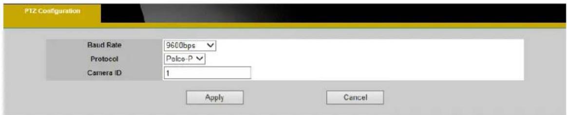
PTZ allows user to change the shooting direction and zoom level of the network camera. The panning, tilting, and zooming functions can be controlled remotely so operators can follow activity and focus in on specific details.
Baud Rate – Select the Baud Rate from the drop-down menu to match the user's needs.
Protocol – Select the Protocol from the drop-down menu (Pelco -P / Pelco-D).
Camera ID – Enter the Camera ID
Click [Apply] to apply settings or [Cancel] to cancel changes.
Network
Network Settings
This section explains how to configure a wired network connection for the camera. There are several ways to setup the camera over the Internet: (1) obtain an available dynamic IP address assigned by a DHCP server, (2) use a static IP, or use PPPoE (Point-to-point over Ethernet). Select the desire setup mode from the IP settings drop-down menu.

LTE/3G(*) ⚠️ NOTE - This function is only available for the GOB models.

- DHCP –If this option is selected, the camera will automatically obtain an available dynamic IP address from the DHCP server each time it connects to the LAN.

- Static IP - Select this option to manually assign a static IP address to the camera. Enter the static IP address, Subnet mask, Default Gateway, Primary and Secondary DNS provided by the ISP.
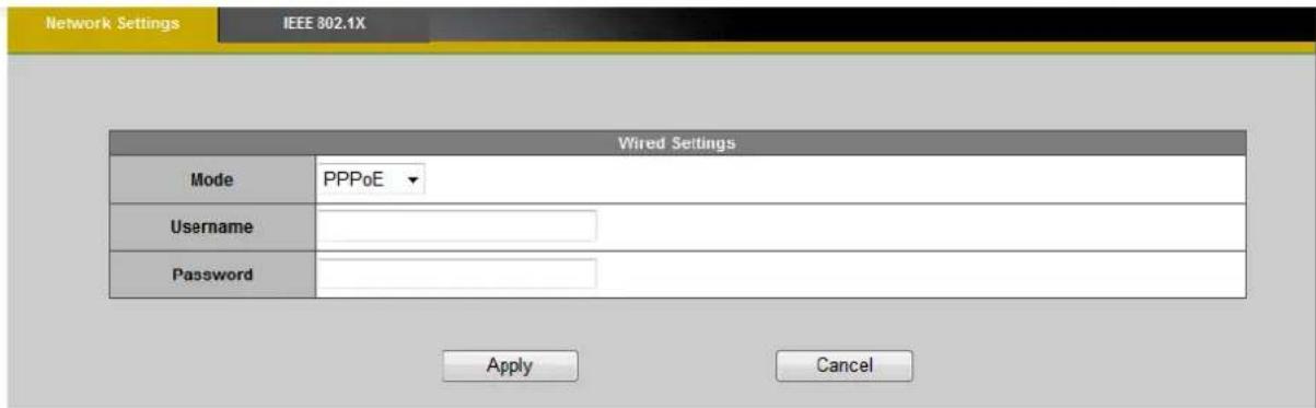
- PPPoE (Point-to-point over Ethernet): Use this mode if connecting to the Internet through a DSL Line.

NOTE - To utilize this feature, it requires an account provided by an
Internet Service Provider. Enter the user name and password provided by the ISP.Click [Apply] to apply settings or [Cancel] to cancel changes.
IEEE 802.1X
IEEE 802.1X is an IEEE Standard for Port-based Network Access Control (PNAC). It provides an authentication mechanism to devices wishing to attach to a LAN or WLAN.
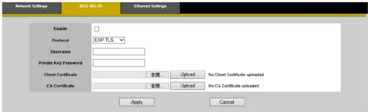
a. Check "Enable" and select the desired Protocol from the drop-down menu.
b. Enter the Username and Private Key Password.
c. Upload the client certificate and CA Certificate for use with the authentication.
d. Click [Apply] to apply settings or [Cancel] to cancel changes.
Ethernet Settings: Auto / Manual

Auto Negotiation: The list box offers 2 choices: [Auto] and [Manual]
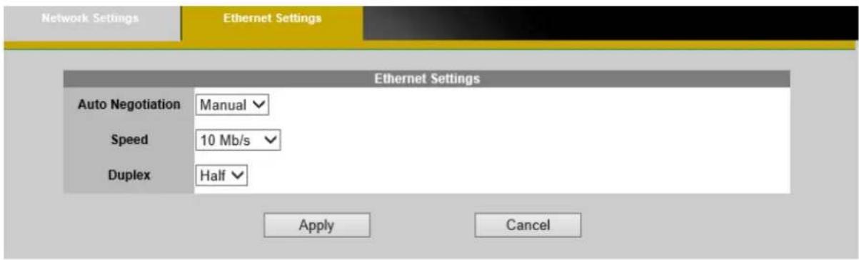
Manual Mode allows user to choose preferable speed and Duplex.
Click [Apply] to apply settings or [Cancel] to cancel changes.
UPnP
Universal Plug and Play (UPnP) simplifies the process of adding a camera to a local area network. Once connected to a LAN, the camera will automatically appear on the intranet.
a. Click "Enable" to enable this function and enter an UPnP name which the camera will appear under on the intranet.

b. Click [Apply] to apply settings or [Cancel] to cancel changes.
DDNS (dynamic domain name service)
DDNS links a domain name to an IP address, allowing user to easily access their
camera even with a changing IP address. Brickcom network cameras are compatible with three DDNS service providers (1) DynDNS, (2) No-IP.

NOTE - Before utilizing this function; please apply for a dynamic domain account from a DDNS
provider.

DynDNS – Enable the DynDNS to allow the camera to have a fixed host and domain name. Refer to the DynDNS website (www.dyndns.com) to apply for a dynamic domain account. When an account has been created, enter the username, password and hostname.
Click [Apply] to apply settings or [Cancel] to cancel changes.
No-IP

No-IP is a DDNS provider which offers DNS services, email, network monitoring and SSL certificates. Email services include POP3 email, outbound SMTP email, backup mail services and mail reflection and filtering. Refer to the No-IP website (www.no-ip.com) to apply for a dynamic domain account. When an account has been created, enter the e-mail address, password and domain name.
Click [Apply] to apply settings or [Cancel] to cancel changes.
EasyLink™

EasyLink™ is a unique Brickcom function which allows user to assign a unique EasyLink name to their network camera's IP address. There is no need to configure the router to open up ports or remember hard-to-memorize IP addresses. When this function is enabled, user can log onto [uniqueEasyLinkname].mybrickcom.com to view the camera's web GUI and live view.
- Check the box to enable EasyLink TM .
- If Auto mode is selected, the following page will be displayed.

NOTE - This mode is recommended.
- Enter a unique EasyLink name whose length must be between 5-32 characters. Click Verify to test if the EasyLink name is available.
- Click START to do the Self-Diagnostic.
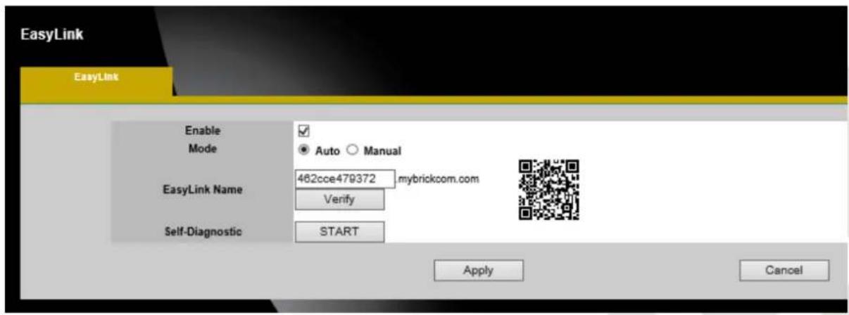
- If Manual mode is selected, the following page will be displayed.

- Enter a unique EasyLink name whose length must be between 5-32 characters. Click Verify to test if the EasyLink name is available.
- Manually enter the Public HTTP Port and RTSP Port or leave the default values.
Click [Apply] to apply settings or [Cancel] to cancel changes.

NOTE - The following conditions may cause EasyLink fail to work:
- The camera is behind more than 1 router.
- The camera's IP address and port setting has a conflict with the router's port forwarding setting.
- EasyLink uses UPnP to exchange port information with the router. The camera must connect to the internet through a router which supports UPnP.
Wireless
These settings control how a Network Camera interacts with a wireless network. User can identify the wireless network and enable wireless encryption.

NOTE – This function is only available for WCB, WOB and WMB models.
Basic Settings

Network Name (SSID) - The Service Set Identifier (SSID) is the network name used to identify the wireless signal emitted from a wireless camera. It is case-sensitive and can be up to 32 characters long.
Wireless devices have a default SSID set by the factory. Brickcom wireless products use Brickcom as the default name. User has to ensure that the SSID setting matches the home network setting to enable the wireless devices.

NOTE - Be careful when including personal information when naming the
SSID as it is viewable by anyone browsing for wireless networks.
Site Survey – Survey the local area for available wireless networks. The user should select their Local Area Network (LAN) from the Site Survey List.
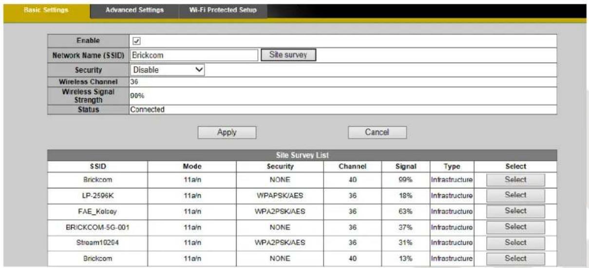
Security - Encryption protects data transmitted over a wireless network. WEP (Wired Equivalent Privacy), WPA-Personal (Wi-Fi Protected Access Personal) and WPA2-Personal offer different security levels for the wireless communication.
Brickcom
A network encrypted with WPA2-Personal is more secure than WPA-Personal and WEP. To protect the information as it passes through the airwaves, it is recommended to enable the highest level of encryption supported by the network equipment. The WPA-RADIUS and WPA2-Enterprise are for the advanced user.
WEP- Wired Equivalent Privacy (WEP) is a basic encryption method which transmits network broadcast messages by using radio signals.

TX Key - Select a key from the drop-down menu.
WEP Encryption - Select the level of WEP encryption that matches the user's wireless network setting.
Key 1-4 - Enter the WEP key(s) manually.
Authentication – User can select the way of authentication from the drop-down menu that matches the user's application. Click [Apply] to apply settings or [Cancel] to cancel changes.
WPA-Personal

Encryption - Supports two encryption methods with dynamic encryption keys:
Temporal Key Integrity Protocol (TKIP) and Advanced Encryption Standard (AES).
Select the algorithm type that matches user's wireless network setting.
Shared Key - Enter a password of 8-63 characters.
Click [Apply] to apply settings or [Cancel] to cancel changes.
WPA2-Persona I

Encryption - WPA2 supports AES encryption method with dynamic encryption keys.
Shared Key - Enter a password of 8-63 characters.

NOTE - If using WPA or WPA2, each device in the wireless network must
use the same WPA or WPA2 method and shared key or else the network will not function properly.
WPA-RADIUS
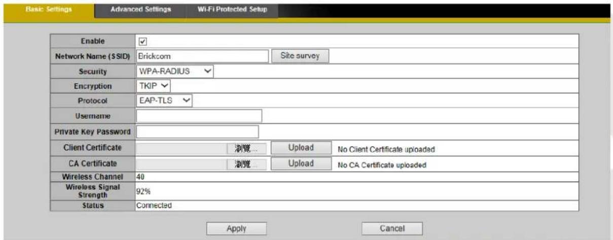
Encryption - Supports two encryption methods with dynamic encryption keys:
Temporal Key Integrity Protocol (TKIP) and Advanced Encryption Standard (AES).
Select the algorithm type that matches user's wireless network setting.
Protocol – Select the type of protocol from the drop-down menu that matches the user's application. While the user select "EAP-PEAP" for protocol, the default inner EAP protocol will set up MS-CHAP v2 automatically.
Username – Enter the username.
Private Key Password – Enter the private key password.
Client certificate - Upload the client certificate for use with the authentication.
CA Certificate - Upload the CA Certificate for use with the authentication.
While the user select “EAP-PEAP” for protocol, the user can check “Validate Server Certificate” to enable the function and upload the CA Certificate for use with the authentication.
Advanced Settings

Network Mode - From the drop-down menu, select the wireless standards running on the network
If there are Wireless-B, Wireless-G and Wireless-N (2.4GHz) devices on the network, select
If there are Wireless-B and Wireless-G devices on the network, select
If there are only Wireless-B devices on the network, select
If there are only Wireless-G devices on the network, select
If there are only Wireless-N (2.4GHz) devices on the network, select
✿ (*)If there are Wireless-A and Wireless-N devices on the network, select
✿ (*)If there are Wireless-A, Wireless-B, Wireless-G and Wireless-N (2.4GHz)
devices on the network, select
✿ (*)If there are only Wireless-A devices on the network, select
✿ (*)If there are Wireless-A, and Wireless-N (5GHz) devices on the network, select
NOTE - (*) These are optional features. Please refer to the Product List for the full list of optional features available for the product.
Radio Band - The settings are available for the Auto-20/40MHz channel and Standard-20 MHz channel.
Enable WMM (802.1e QoS) - WMM is a wireless Quality of Service feature that improves quality for audio, video, and voice applications by prioritizing wireless traffic. To use this feature, the wireless client devices on the network must support Wireless WMM. The default setting is [Enabled]. To disable this feature, select [Disable].
Click [Apply] to apply settings or [Cancel] to cancel changes
Wi-Fi Protected Setup

Use this method if the client device has a Wi-Fi Protected Setup PIN number.
- Enter the AP's SSID from the device in the field.
- Click
to start WPS. - Click to start WPS.
-
Click "Enable" to enable the WPS Button. If this feature is not enabled, the user will not be able to use the WPS button.
-
Click [Apply] to apply settings or [Cancel] to cancel changes.
LTE/3G
Use this option if using a 3G SIM card to set up the wireless connection to transmit the video/audio.

Enable the function:
a. Enter the APN (Access Point Number), Dial Number, PIN Code, PUK Code, User Name and Password provided by the ISP.
b. Click [Apply] to apply the settings. The message below will be displayed if the 3G settings were successfully applied.

c. Before disconnecting the network cable of the network camera, please obtain the IP Address by using EasyConfig. The LTE/3G connection IP Address will be displayed in the IP Address column.
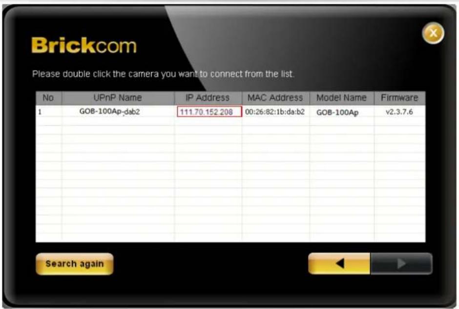
d. The network camera can now be accessed over the LTE/3G network.
To access the video feed through the internet, please open the IE browser and enter the network camera's IP address. A dialog window will pop up requesting the username and password. The default username is

HTTP/HTTPS

HTTP – (HyperText Transfer Protocol) - This protocol allows for TCP protocol quality without having to open specific ports for streaming. User inside a firewall can utilize this protocol to allow streaming data through.
HTTPS - (Hypertext Transfer Protocol over SSL) - This protocol allows authentication and encrypted communication over SSL (Secure Socket Layer). It helps protect streaming data transmission over the Internet on a higher security level than HTTP.
For HTTPS to work properly, user have to create and install a certificate of their own.
1. Click "Continue to this website" to install.

There is a problem with this website's security certificate.
The security certificate presented by this website was issued for a different website's address.
Security certificate problems may indicate an attempt to fool you or intercept any data you send to the server.
We recommend that you close this webpage and do not continue to this website.
√ Click here to close this webpage.
Continue to this website (not recommended).
More information
- Enter the User name and Password of the camera.

- Click "Certificate Error" on the top right corner of the window to view the certificate.

- Click "Install Certificate" and follow the steps to finish the installation.

OpenVPN
When user and IP camera in the different networks, OpenVPN allows camera preform in a virtual network, and User can access to the IP camera through OpenVPN.
- Click [Browse] and select
document, then click [Upload] to install. - Click [Browse] and select
document, then click [Upload] to install. - Click [Browse] and select
document, then click [Upload] to install. - In advanced Settings column, Click [Browse] and select
document, then click [Upload] to install. - Back to Basic Settings column; check the
option. - Enter
、 , Choose type. - Enter
and . - Check the
option. - Click [Apply] to apply settings.
- Check
to ensure connected situation
Event
Event Settings
When an event (such as unauthorized movement) occurs, the camera can be scheduled to perform certain actions. An Event Type is a set of parameters that defines these actions. This section describes how to configure the camera to perform certain actions when events occur.

Click [Add Event] on the Event Settings page. The Event Setup page will appear.
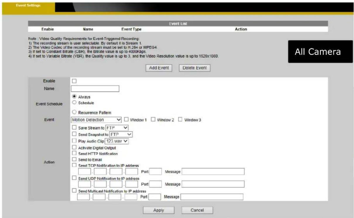

How to Set Up an Event Schedule
Event Schedule describes how and when the camera performs certain actions.
- Check
and enter a descriptive name for the event schedule. - Set Event Schedule to define when the event is activated by selecting from Always (24 hours), Schedule or Recurrence pattern.
a. If Schedule is selected from the Event Schedule, the following page will be displayed:

A Scheduled Event can be programmed for certain times and day. Click individual boxes to schedule specific times for the camera to detect events.
b. If Recurrence Pattern is selected, the following page will be displayed.


c. An event schedule can be programmed to recur at different times according to the user's needs. Select the days for the event schedule to occur. Select a start time and specify the duration.
d. Define what will trigger an event to occur by selecting an option from the Event drop-down list.
e. Select the Actions that will occur when the event is triggered.
When


- Sender - Enter the email address of the sender.
- Recipient - Enter the email address of the recipient. To enter multiple recipients, separate each by using a comma.
- Sender's Name – Enter the sender's name that will appear in the recipient's inbox.
- Subject - Enter the title of the email.
When complete, click [Apply] to save new event or [Cancel] to delete the event.
Brickcom
The new event will appear on the event list. To edit an event setting, please select the event from the list. To remove an event setting from the list, select an event name from the list and then click [Delete Event]. Click [Add Event] to add more events.

NOTE - Refer to the Audio Clip section for more details about the "Play Audio Clip" action.
Motion Detection
Motion can be detected by measuring changes in the speed or vector of objects in the monitored area. This section explains how to configure the Network Camera to enable motion detection.

Detection Setting – Use this setting to enable and define the motion detection windows. The user can defined up to three areas on the live view window for motion detection.
Select
- Check the box to enable the window.
- Use the mouse to resize or move the motion detection window.
- Adjust the "Sensitivity" level. Lower sensitivity levels will result in more activity
Brickcom
needed to trigger an event.
-
Adjust the "Threshold" level. The higher the threshold is, the more proportion of the region is needed to trigger an event.
-
The chart below the Live View window indicates the activity in the Motion Detection window. When motion in the motion detection window is detected by the camera, a vertical bar will be displayed in the chart; when the motion is detected and the motion activity level is over the defined threshold, the color of the bar will change. User can use this feature as a trigger source to send photos or videos to a remote server via email or FTP.
Click [Apply] to apply settings or [Cancel] to cancel changes.
Intelligent Video Analysis ( IVA )
Detect and trace the object in view, alert to objects intrude or across into the security line
Intrusion Detection
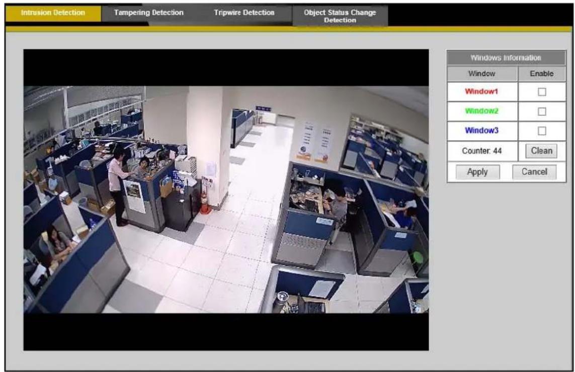
Intrusion Detection
User is able to set numerous intrusion windows and the device can monitor those regions. The device will send a real-time alerting to the user while the suspicious object appears in secured zone.
- Enable the window option and adjust dimension of the window.
- To activate settings, please click [Apply] to apply settings or [Cancel] to cancel changes.

NOTE – Environment Setting Restriction for Intrusion Detection
To ensure better user experience, please follow the installing instructions below:
- Camera should be installed at depression angle, which helps device detection much clearer and more effective.
- Set cameras with adequate and even illumination; either avoid backlighting environment or enable WDR Feature to ensure clear observation.
- Make sure the Intrusion Windows not too close to the edge for more precise detection.
- It needs at least 2 seconds to verify effective objects. If the moving objects appear on the screen less
than 2 seconds, it would be defined as a noise.
-
Too Big or too small objects might cause misjudgment. The Suitable size of object should be 1/140\~1/10 of screen.
-
Low contrast environment might cause system misjudgment. Enlarge the Intrusion Windows can enhance accuracy of detection in such case.
Tampering Detection
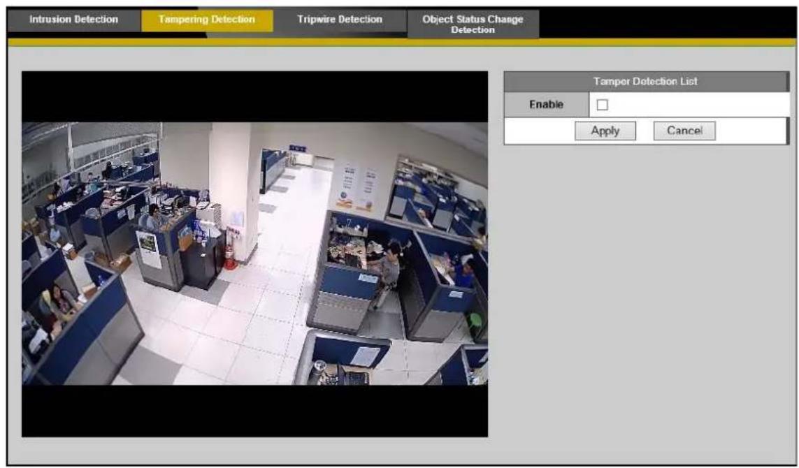
Tampering Detection
Tampering alarm technology will automatically alert to security staffs while the device have been damaged purposely or being interfered, which allows staffs to protect camera and against the violence. Active tampering alarm detects incidents include Out of Focus, Scene too Dark, Scene too Bright and Interference Sensitivity.
1. Enable the option for further settings:
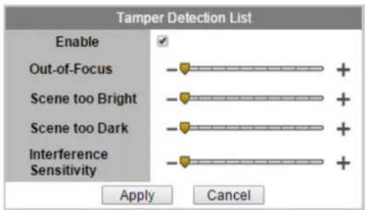
Out-of-Focus: Drag the slider bar to adjust Focus clarity
Scene too Bright: Drag the slider bar to adjust Brightness.
Scene too Dark: Drag the slider bar to adjust Darkness.
Interference Sensitivity: Drag the slider bar to adjust Interference Sensitivity.
- Click [Apply] to apply settings or [Cancel] to cancel changes.
Cordon Detection

Cordon Detection:
User can set a cordon to secure specific area away from dangers. While people or other moving objects cross the cordon, the camera will automatically send the alarm to the user with several actions (video clip, snapshot, and store to SD) to help the user to understand the situation and prepare the reaction.
Enable the
• [Cordon mode] window
| Mode | Direction | |
| Set Cancel |
- Activate the button, click and draw the cordon.

- Click to set pass-through direction.
- Click [Set] to apply settings or [Cancel] to cancel changes.
• [Cordon Information] window
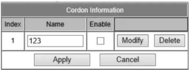
In
![Brickcom OB-300NE STAR - • [Cordon Information] window - 2](/content/2026/06/1187715/images/304bf4b646b82dc79d1532674018b3a2091f20d0f87585e86544e25bcebf38d9.jpg)
NOTE – Environment Setting Restriction for cordon Detection
- Camera should be installed at depression angle, which helps device detection much clearer and more effective.
- Set cameras with adequate and even illumination; either avoids backlighting environment or enable WDR Feature to ensure clear observation.
- It needs at least 2 seconds to verify effective objects. If the moving objects appear on the screen less than 2 seconds, it would be defined as a noise.
- Too Big or too small objects might cause misjudgment. The Suitable size of object should be 1/140\~1/10 of screen.
- Low contrast environment might cause system misjudgment. Enlarge the Intrusion Windows can enhance accuracy of detection in such case.
Object Status Change Detection

Object Status Change Detection
User can focus on several objects and set up the alert area to protect the important properties. While the object status has changed, the camera will send the alarm to inform the user that the property may have been stolen by burglars.
- User can enable the detection window and adjust dimension of the windows.
- To activate settings, please click [Apply] to apply settings or [Cancel] to cancel changes.
records the total number of people who have passed through the setting windows. Click [Clean] to erase counting number and start a new counting.

NOTE – Environment Setting Restriction
- Camera should be installed at depression angle, which helps device detection much clearer and more effective.
- Set cameras with adequate and even illumination; either avoid backlighting environment or enable WDR Feature to ensure clear observation.
- It will need about 1 \~ 2 minutes to start up OSC function
- Too Big or too small objects might cause misjudgment. The Suitable size of object should be 1/140\~1/3 of screen.
Brickcom
- Low contrast environment might cause system misjudgment. Narrow the detection windows can enhance sensitivity of detection.
People Counting
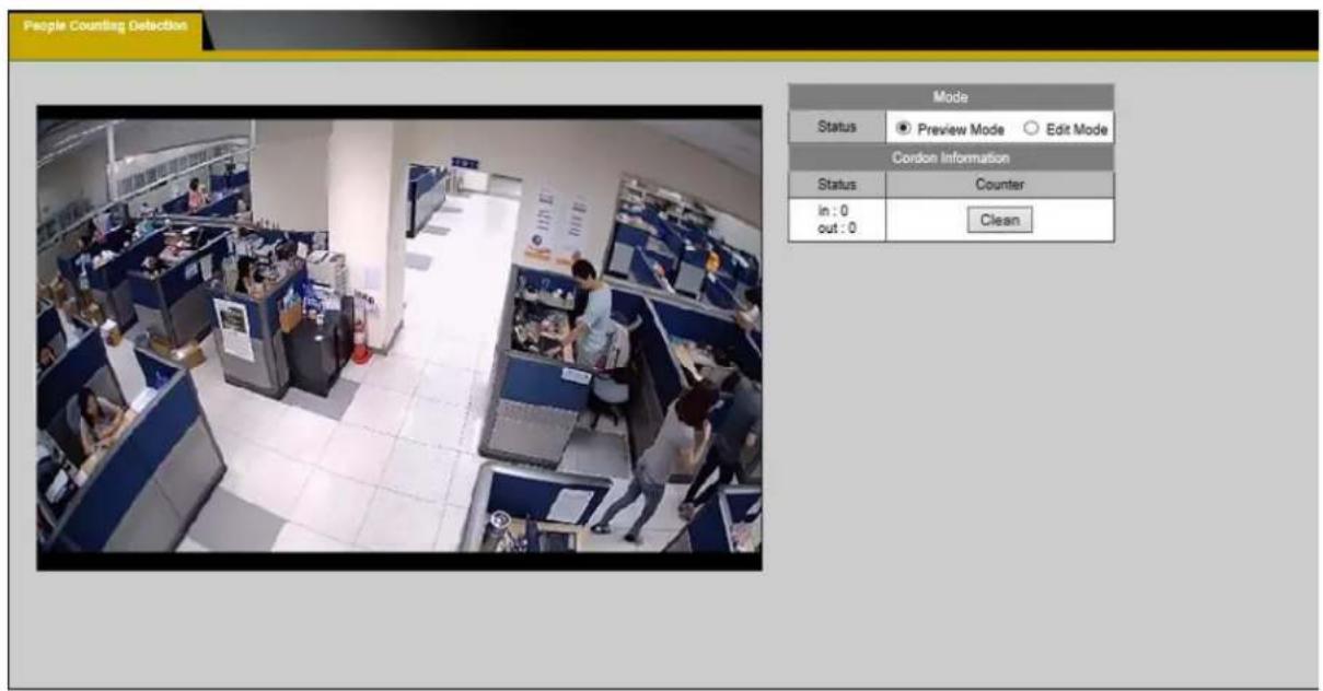
People counting is Independent from other IVA function

NOTE – Environment Setting Restriction for People Counting
- Set cameras with adequate and even illumination
- Background scene is recommended to be light color than dark color for better result
- The people movement direction should approximately parallel the
.
The offset angle (angle a in picture) should not bigger than 20°
The tilt angle (angle b in picture) recommended between 30°\~60°
Please referred to picture (1)

Picture (1)
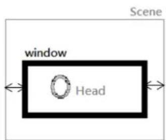
Picture (2)
- Width of people counting window is about the detected aisle width.
Make detected aisle occupied about 2/3\~3/4, in the middle of scene; two side of window preserve some space to the edge of scene for detection accuracy. Please referred to picture (2): - Recommended height of people counting window is 1.5\~2 head height. The Suitable size of head should be 1/45\~1/16 of window.
Digital Input

User can select the desired DI status from the drop-down menu. When the DI status meets the specified condition, the camera will be triggered to take the corresponding actions. Click [Apply] to apply settings or [Cancel] to cancel changes.
Digital Input
A Digital Input will detect a voltage or no voltage condition, and generates a logical 0 or 1, high or low. It could be used to trigger an alarm or other events.

Five mode (High/Low/Rising/Falling/Rising&Falling) can be selected from drop-down menu .Click [Apply] to apply settings or [Cancel] to cancel changes.
Audio Detection

User can schedule an event to be triggered if there is a change in the sound level
of a monitored area. Audio detection can be used to measure change in the ambient voice. Select the sensitivity from the drop-down menu.


Display the current sound level.
Click [Apply] to apply settings or [Cancel] to cancel changes.
Temperature Detection

The temperature detection function is used to report the current chamber temperature of the camera. The camera can also be programmed to trigger an event if the current chamber temperature of the camera is higher than the upper bound or lower than the lower bound.
Unit - Set the unit of measurement to Fahrenheit (°F) or Celsius (°C).
Upper bound & Lower bound – Set the temperature boundaries. The applicable values range from 0 °C to 100 °C (32 °F to 212 °F).
Click [Apply] to apply settings or [Cancel] to cancel changes.
PIR (Professional Cube Only)

The PIR (Passive Infrared) sensor measures infrared light radiating from objects in its field of view. This can be used to detect a moving object, such as a person, in dimly lit areas.
Sensitivity – Adjust the sensitivity of the PIR Sensor from the drop-down menu. Higher sensitivity levels will increase the range of the PIR Sensor.
Notifications
Use the tools in this section to specify what type of notification will be sent when an event occurs. The camera can send buffered images to an FTP server, Samba, Email, or HTTP.
FTP Settings
File Transfer Protocol (FTP) is used as an application component to automatically transfer files for program internal functions. Select "Primary FTP Server" from the Server Selection drop down menu to send media files to a FTP server when an event is triggered. Enter the FTP IP address or hostname. By default, the FTP port server is set to 21. Enter the account name, password and FTP Path to configure the settings.
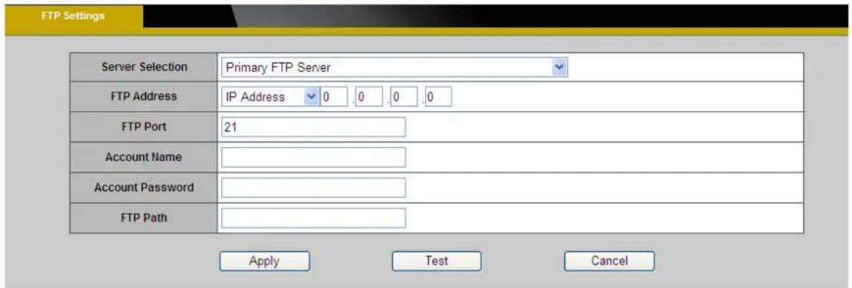
Click [Apply] to apply settings or [Cancel] to cancel changes.
E-mail Settings
Select "Primary Email Server" option from the Server Selection drop down menu to send media files to an email server when an event is triggered.
SMTP Server - Enter the server host name of the email server.
SMTP Port - Enter the port number of the email server; by default, the SMTP port is set to 25.
Authentication - Select the authentication type from the drop-down menu.
Email Account - Enter the user name of the email account if necessary.
Email Password - Enter the password of the email account if necessary.
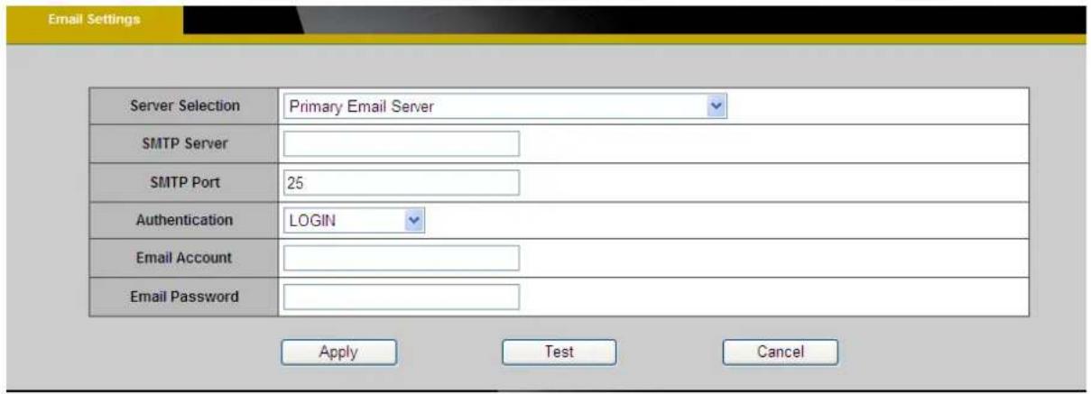
Click [Apply] to apply settings or [Cancel] to cancel changes.
Samba Settings
Select this option to send the media files via a network neighborhood when an event is triggered.
Server Address - Enter the IP address of the Samba server.
User Name - Enter the user name of the Samba server.
Password - Enter the password of the Samba server.
Work Group - Enter the workgroup of the Samba server.
Shared Folder - Enter the share folder of the Samba server.

Click [Apply] to apply settings or [Cancel] to cancel changes.
HTTP Settings
Select this option to send the notification message via an HTTP connection when an event is triggered.

URL –Specify the URL to send HTTP requests. The URL is normally written as:
http://ip_address/ notification.cgi?parameter
ip_address – IP address or host name of the HTTP host.
Parameter – the notification parameter(s) to send to the HTTP host, if necessary.
(Example: http://192.168.1.1/notification.cgi?event=MD&camera=FB-100A)
Message - Enter the message notification that will be sent when an event is triggered. Enter the user name and password if necessary.
Click [Apply] to apply settings or [Cancel] to cancel changes.
Digital Output (DO)

The DO socket allows the IP camera to send output to an external device. While executing the DO notification action, the status of the camera's DO interface will be changed to the specified setting (OPEN or GROUNDED) for the specified number of seconds to activate the connected external device.

NOTE –User should select the option according to the specification of their external device.
Video Clip/Snapshot

This function is used to determine when video clips or snapshots will be recorded and stored after an event is triggered.
NOTE – the value showed in (*) is for Elite series
Pre-Alarm Buffer – Up to 10 (2*) seconds of video before the event is triggered can be stored in the local storage or uploaded to the server. Enter the desired length of time.
Post-Alarm Buffer – Up to 30 (2*) seconds of video after the event is triggered can be stored in the local storage or uploaded to the server. Enter the desired length of time.
Maximum Buffer Size –Specify the maximum file size allowed.
Click [Apply] to apply settings or [Cancel] to cancel changes.
Pre-Alarm Snapshot – Up to 5 (2*)Snapshot before the event is triggered can be stored in the local storage or uploaded to the server. Enter the desired number of frame.
Post-Alarm Snapshot - Up 5 (2*)Snapshot after the event is triggered can be
stored in the local storage or uploaded to the server. Enter the desired number of frame.
Audio Clip
Audio Recording – Audio clips can be recording and played when an event occurs.

Click [Browse] to import a file from a local hard drive or network disk. Select the file and click [Import].

NOTE – The camera can only play audio clips which are saved as .wav files
with G.711 u-law encoding in 8000 Hz sampling rate.
To record a new clip using the camera's microphone:
- File Name-Enter a file name.
- Duration – Drag the drop-down List to choose the number of seconds to record.
- Click [Record] to record the new audio clip.
- The new audio clip will appear on the audio clip list.
- Select an audio clip file from the Audio Clip List.
a. Play- Select to hear the audio clip
b. Stop- Select to stop playing the audio clip.
c. Delete- Select to delete an audio clip.
d. Export- Select to export the audio clip to a local hard drive or network disk.
LED Light (Professional Cube Only)

Mode – Select "Keep active during event" or "Keep active for" a specific amount of time when an event is triggered.
LED Control - The LED on the front of the camera can be set to flash at a configurable interval when an event is triggered. From the Activate drop-down menu, select a percentage which the LED will brighten to. When the LED reaches the selected percentage, it can be configured to fade to off or turn off.
Select the option from the Inactive menu.
Click [Apply] to apply settings or [Cancel] to cancel changes.
System
System Log
Log – Set up the camera to record a system log when an event is triggered.
![LOG_WARNING-Wireless :Wireless connection for SSID [Brickcom] is down, Thu Jan 1 00:00:12 2009 LOG_NOTICE-WebServer :User [admin] logged in to [web server]. Thu Jan 1 00:02:35 2009 LOG_NOTICE-WebServer :User [admin] logged in to [web server]. Thu Jan 1 00:02:52 2009 LOG_INFO-stream :Channel [1] star…](/content/2026/06/1187715/images/35a126dd88dde423ca6d85c43dde64752af04f819a1daf4155bb59d767f692f0.jpg)
This page displays the system's log in chronological order. The system log is stored in the camera's buffer area and will be overwritten when the buffer area is full.Click [Retrieve] to retrieve the log or click [Save to file] to save the system log.
Remote Logging
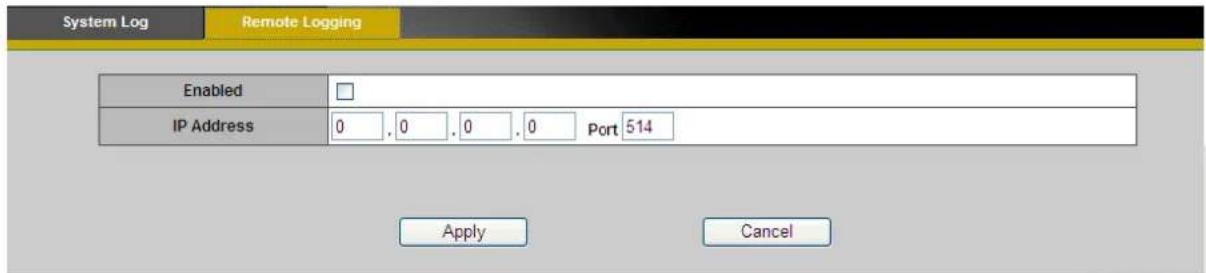
The user can configure the camera to send the system log file to a remote server as a log backup.
a. Click to enable remote log and enter the IP address of the remote server.
b. Enter the port number of the remote server.
Click [Apply] to apply settings or [Cancel] to cancel changes.
Date and Time
Time Synchronization : Mode
- Set Manually – The user can enter the desired date and time, or check "Clone"
to copy the date and time of the computer to the camera.
| Time Synchronization | |
| Mode | ● Set Manually ○ Synchronize with NTP server |
| Date | 2014 / 9 / 26 (yyyy/mm/dd) |
| Time | 13 : 23 : 28 (hh:mm:ss) |
| Clone from PC | □ Clone (Current Time: 2014/9/26 14:19:49) |
- Synchronize with NTP server – NTP is a protocol for synchronizing the clock of a computer system. Enter the address of the desired NTP servers in NTP Server 1 and Server 2.
| Time Synchronization | |
| Mode | ○ Set Manually ● Synchronize with NTP server |
| NTP Server1 | tick.stdtime.gov.tw |
| NTP Server2 | clock.stdtime.gov.tw |
Time Zone - Select the local time zone from drop-down menu, or choose the "User Defined" from drop-down menu and enter the country name and adjust the offset (Hours and Minutes).
| TimeZone | |
| TimeZone | (GMT+08:00)Taipei |
| Country | |
| Offset | Hours: +0 Minutes: 00 |
Daylight Saving Time - Enable this option to update for Daylight Saving Time.
| Daylight Saving Time | ||
| Daylight Saving | ○ Disable ● Enable Manual √ | |
| Type | Date √ | |
| Start Date | Month: 1 √ Day: 1 √ | |
| End Date | Month: 1 √ Day: 1 √ | |
Click [Apply] to apply settings or [Cancel] to cancel changes.
Device Information
System Information – Displays the complete system information of the camera.
| LAN MAC Address | 98.3B:16.4B:C5.42 |
| Firmware Version | v3.2.3.5.6 |
| Product Name | FB-300Np |
| UPnP Name | FB-300Np-c542 |
Network Settings – Displays the complete network settings information of the camera.
| System Information | Network Settings | Video/Audio Settings | Client Information |
| IP Information | |||
| IP Setting Type | DHCP | ||
| IPv4 | |||
| IP Address | 192.168.1.115 | ||
| Subnet Mask | 255.255.255.0 | ||
| Default Gateway | 192.168.1.1 | ||
| Primary DNS | 192.168.1.1 | ||
| Secondary DNS | |||
| IPv6 | |||
| IP Address | fe80::442c:ceff.fe47:9372/64 | ||
| IPv6 Subnet Prefix Length | 64 | ||
| Default Gateway | |||
| Primary DNS | |||
| Secondary DNS | |||
| Network Services | |||
| UPnP | Enable | ||
Video/Audio Settings – Displays the complete video/audio settings information of the camera.
| System Information | Network Settings | Vidoc/Audio Settings | Client Information | |
| Stream 1 | ||||
| Video Codec | H 264 | |||
| Video Resolution | 1920x1080 | |||
| Video Frame Rate | 30 fps | |||
| Video Bitrate | 8000 Kbps | |||
| Audio Codec | N/A | |||
| Multicast IP | N/A | |||
| Stream 2 | ||||
| Video Codec | MJPEG | |||
| Video Resolution | 640x480 | |||
| Video Frame Rate | 25 fps | |||
| Video Quality | 3 | |||
| Audio Codec | N/A | |||
| Multicast IP | N/A | |||
| Stream 3 | ||||
| Video Codec | H.264 | |||
| Video Resolution | 320x180 | |||
| Video Frame Rate | 30 fps | |||
| Video Bitrate | 256 Kbps | |||
| Audio Codec | N/A | |||
| Multicast IP | N/A | |||
Wireless (*)
| System Information | Network Settings | Video/Audio Settings | Wireless |
| Wireless MAC Address | 00:26:82:1B:DB:92 | ||
| Radio Band | Auto-20/40MHz Channel | ||
| Network Mode | BGN-Mixed | ||
| Security | Disabled | ||
| Network Name (SSID) | Brickcom_MARS | ||
| Wireless Channel | 6 | ||
| Wireless Signal Strength | 85% | ||
| Status | Connected | ||
Client Information- Displays the RTSP Client. You will see a list of RTSP clients with the following information: IP Address and channel.

Storage Management
Storage Management is used to view all the recorded files in the inserted memory card. Depending on the model used, the SD/SDHC/SDXC card or the micro-SD/SDHC/SDXC card may be used.

❖ Click [Reload] to refresh the list of recorded files.
❖ Click [Remove] to safely remove the memory card.
❖ Click [Format] to format the memory card.
Left click on the folder to list the recorded files. The user can either play the snapshot of the recorded files by moving the mouse pointer over the file or double click on a file to play it. Right click on the folder to download, play or delete the recorded files.

NOTE – The user may need to install QuickTime multimedia framework to play the video clips.
Advanced Settings
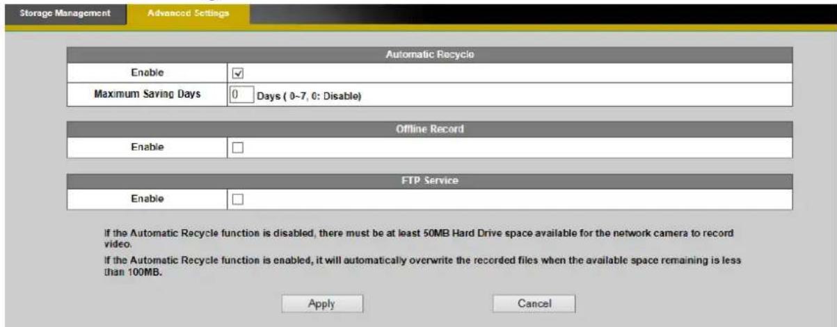
Automatic Recycle (*) – Enable to automatically overwrite older files when the available space remaining on the memory card is less than 100MB. If the Automatic Recycle function is disabled, there must be at least 50MB hard drive space available for the camera to be able to record video files. Enter the maximum saving days to fit your needs.
Offline Record – Enable to keep recording if the Network Camera is offline.
FTP Service – Click “Enable” to activate the FTP service of the camera for the user to download the video/snapshot files with an FTP client.
LED Indicators
The LED on the front of the camera can be configured to remain unlit. Check "OFF" to enable this function.

Click [Apply] to apply settings or [Cancel] to cancel changes.
VMS Compatibility

ONVIF
The parameters are used to address the compatibility issues. In most cases, the user can use the default values.
Maintenance
User Management
This section explains how to enable password protection and create multiple accounts.
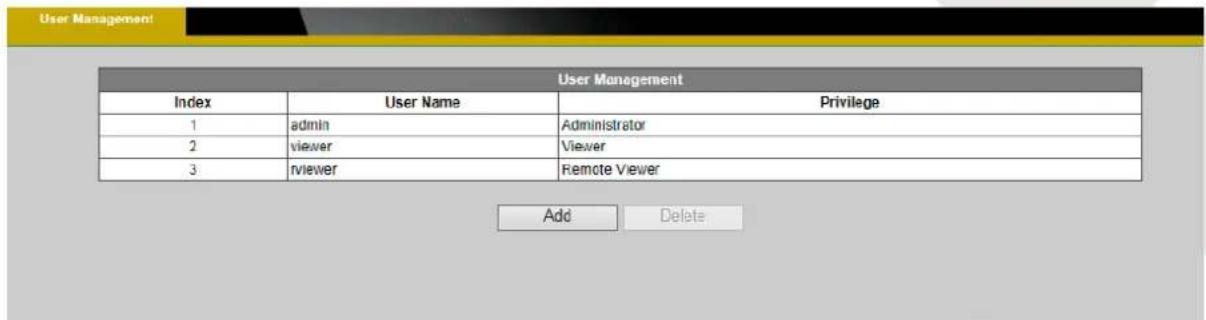
The administrator account name is "admin", which is permanent and cannot be deleted.
Click [Add] to create an account.

- Enter the new user's name, password and confirm password. Administrators can add up to 10 user accounts.
- Select the privilege level for the new user account from the drop-down list. Privilege levels can be assigned as:
- Administrator - user has access to view and change the Configuration page. User with administrator privilege can change other user's access rights and delete user's accounts. Click [Delete] or [Update] to delete or modify a user's account.
✿ Viewer - user can only access the main page for live viewing.
Remote Viewer - user can only access the main page for live viewing by using TCP protocol.
Language

Select the desired language from the radio button. Click [Apply] to apply settings
or [Cancel] to cancel changes.
IP Filter
The IP Filter is used to filter the IP addresses which are able to access the network camera. Enable the IP Filter and select to allow or deny a range of IP addresses access to the server. Click [Add to list] to add the IP range to the IP filter list.

Click [Apply] to apply settings or [Cancel] to cancel changes.
Firmware Upgrade
This feature allows the user to upgrade the camera firmware. It will take a few minutes to complete the process.
NOTE - Do not power off the camera or interrupt the camera during the upgrade.
Click [Browse] and specify the firmware file, then click [Upgrade]. The camera will be upgraded and reboot automatically when the upgrade is finished.

The following message will show during the firmware upgrading process.
WARNING: DO NOT UNPLUG THE ETHERNET CABLE OR THE POWER CORD DURING THE FIRMWARE UPGRADE!
8%
Uploading the firmware image file...
Configuration
This feature allows the user to export/import the configuration files of the network camera.
Import/Export - Click [export] to pop up a dialog to indicate the location and file to export. Click [browse] to indicate the location and file of the camera configuration and click [import] to import the configuration file back into the network camera.
Import / Export
| Export | Export | |
| Import | Please select a file to import | Browse... |
| Import | ||
Reset to Default
This section is used to restore the camera to default factory settings. Check the boxes to preserve the Network settings, Date and Time settings, EasyLink settings, Language settings and HTTP/HTTPS settings. Click [Apply] to restore the camera to default factory settings.
Reset to Default
Press the Apply button to restore the Network Camera settings to factory default values, except for the following:
□ Network settings
□ Date and Time settings
□ EasyLink settings
□ Language settings
□ HTTP/HTTPS settings
Apply
Cancel
Reboot

This feature will reboot the camera. Click Apply to begin. A message will pop up asking "The device will reboot. Are you sure?" Click "OK" to continue. The camera will take about one minute to reboot.

The following message will show during the rebooting process.

When completed, the live video page will be displayed in the web browser.
- BRICKCOM SOFTWARE USER'S MANUAL
- TABLE OF CONTENTS
- LOG IN THE CAMERA 4
- INSTALLING THE PLUG-IN ....4
- LIVE VIEW 6
- CONFIGURATION 13
- CAMERA/VIDEO/AUDIO 13
- CAMERA CONTROL 32
- NETWORK 35
- EVENT....52
- NOTIFICATIONS....66
- BRICKCOM
- SYSTEM....71
- MAINTENANCE....77
- LOG IN THE CAMERA
- INSTALLING THE PLUG-IN
- LIVE VIEW
- CHANNELS
- PROTOCOL
- CAMERA POSITION: CEILING, GROUND, WALL
- STATUS ICONS
- PTZ CONTROL (OSD SERIES AND PZ-040 SERIES ONLY)
- CONFIGURATION
- CAMERA/VIDEO/AUDIO
- SCENE LIST
- SCENE SETTING-SCHEDULE
- SCENE SETTING - DIGITAL INPUT
- SCENE SETTING – ENTRANCES / ELEVATORS
- PROFILE SETTING
- EXPOSURE CONTROL
- VIDEO
- FOR EACH STREAM, THE FOLLOWING SETTINGS ARE AVAILABLE
- BRICKCOM EVBR
- I-STREAM
- VIDEO OVERLAY
- TIMESTAMP
- TEXT
- RTSP SERVER
- RTP/RTCP
- AUDIO
- ADVANCED SETTINGS
- FOCUSEASY (*)
- MULTICAST
- ROI (REGION OF INTEREST)
- PRIVACY MASK CONTROL
- CAMERA CONTROL
- PRESET POINT
- PATROL SETTINGS
- PTZ CONFIGURATION
- NETWORK
- NETWORK SETTINGS
- IEEE 802.1X
- UPNP
- DDNS (DYNAMIC DOMAIN NAME SERVICE)
- NO-IP
- EASYLINK™
- WIRELESS
- BASIC SETTINGS
- WPA-PERSONAL
- WI-FI PROTECTED SETUP
- LTE/3G
- CLICK "CONTINUE TO THIS WEBSITE" TO INSTALL
- EVENT
- EVENT SETTINGS
- HOW TO SET UP AN EVENT SCHEDULE
- MOTION DETECTION
- INTELLIGENT VIDEO ANALYSIS ( IVA )
- INTRUSION DETECTION
- NOTE – ENVIRONMENT SETTING RESTRICTION FOR INTRUSION DETECTION
- TAMPERING DETECTION
- ENABLE THE OPTION FOR FURTHER SETTINGS
- CORDON DETECTION
- [CORDON INFORMATION] WINDOW
- NOTE – ENVIRONMENT SETTING RESTRICTION FOR CORDON DETECTION
- OBJECT STATUS CHANGE DETECTION
- NOTE – ENVIRONMENT SETTING RESTRICTION
- PEOPLE COUNTING
- NOTE – ENVIRONMENT SETTING RESTRICTION FOR PEOPLE COUNTING
- DIGITAL INPUT
- AUDIO DETECTION
- TEMPERATURE DETECTION
- PIR (PROFESSIONAL CUBE ONLY)
- NOTIFICATIONS
- FTP SETTINGS
- E-MAIL SETTINGS
- SAMBA SETTINGS
- HTTP SETTINGS
- DIGITAL OUTPUT (DO)
- VIDEO CLIP/SNAPSHOT
- NOTE – THE VALUE SHOWED IN (*) IS FOR ELITE SERIES
- AUDIO CLIP
- LED LIGHT (PROFESSIONAL CUBE ONLY)
- SYSTEM
- SYSTEM LOG
- REMOTE LOGGING
- DATE AND TIME
- TIME SYNCHRONIZATION : MODE
- DEVICE INFORMATION
- WIRELESS (*)
- STORAGE MANAGEMENT
- LED INDICATORS
- VMS COMPATIBILITY
- ONVIF
- MAINTENANCE
- USER MANAGEMENT
- LANGUAGE
- IP FILTER
- FIRMWARE UPGRADE
- RESET TO DEFAULT
- REBOOT
Brand : Brickcom
Model : OB-300NE STAR
Category : Security Camera