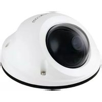
MD-300NP STAR - Security Camera Brickcom - Free user manual and instructions
Find the device manual for free MD-300NP STAR Brickcom in PDF.


| Product Type | Mini Dome Network Camera |
| Brand | Brickcom |
| Model | MD-300NP STAR |
| Image Sensor | Megapixel CMOS |
| Resolution | 1080p (1920x1080) @ 30fps |
| Lens | Exchangeable, 360° panoramic lens option (360P) |
| Day/Night | Yes, with IR cut filter |
| Video Compression | H.264 / MPEG-4 / M-JPEG |
| Network Interface | 10/100 Base-T, RJ-45 |
| Power Supply | PoE (802.3af) or DC 12V |
| Power Consumption | Approx. 5W |
| Local Storage | MicroSD/SDHC/SDXC up to 128GB |
| Ingress Protection | IP67 |
| Vandal Resistance | IK10 |
| Dimensions (Diameter x Height) | Approx. 120 mm x 80 mm |
| Weight | Approx. 500 g |
| Operating Temperature | -10°C to 50°C |
| Operating Humidity | Up to 90% non-condensing |
| Included Accessories | CD, lens tool, Allen key, mounting adapter, screws, dry bag, alignment sticker |
| Compliance | FCC Class B, CE |
| Web Browser Support | Internet Explorer 6.0 SP2 or higher |
Frequently Asked Questions - MD-300NP STAR Brickcom
User questions about MD-300NP STAR Brickcom
0 question about this device. Answer the ones you know or ask your own.
Ask a new question about this device
Download the instructions for your Security Camera in PDF format for free! Find your manual MD-300NP STAR - Brickcom and take your electronic device back in hand. On this page are published all the documents necessary for the use of your device. MD-300NP STAR by Brickcom.
USER MANUAL MD-300NP STAR Brickcom
Hardware User's Manual
Megapixel Day & Night Mini Dome Network Camera Quality Service Group
Brickcom
Table of Contents
Before You Use This Product ....1
Regulatory Information 2
Chapter 1 - Package Contents ....3
Chapter 2 - Mini Dome Network Camera Overview ......4
Chapter 3 - Device Appearance Description....5
Chapter 4 - LED Behavior ....7
Chapter 5 - Installation....8
5.1 Hardware Installation ....8
5.2 Camera Connection....11
5.3 How to Adjust 360P Lens (MD-500Ap/300Np-360P-AL only) ....14
5.4 System Requirements....16
5.5 Software Installation....17
5.5.1 EasyConfig 25
Before You Use This Product
In many countries, there are laws prohibiting or restricting the use of surveillance devices. This Network Camera is a high-performance, web-ready camera which can be part of a flexible surveillance system. It is the user's responsibility to ensure that the operation of this camera is legal before installing this unit for its intended use.
Upon opening the product's package, verify that all the accessories listed on the "Package Contents" are included. Before installing the Network Camera, read the warnings in the "Quick Installation Guide" to avoid misuse. When installing the Network Camera, carefully read and follow the instructions in the "Installation" chapters to avoid damages due to faulty assembly or installation.
Brickcom
Regulatory Information
Federal Communication Commission Interference Statement
This equipment has been tested and found to comply with the limits for a Class B digital device, pursuant to Part 15 of the FCC Rules. These limits are designed to provide reasonable protection against harmful interference in a residential installation. This equipment generates uses and can radiate radio frequency energy and, if not installed and used in accordance with the instructions, may cause harmful interference to radio communications. However, there is no guarantee that interference will not occur in a particular installation. If this equipment does cause harmful interference to radio or television reception, which can be determined by turning the equipment off and on, the user is encouraged to try to correct the interference by one of the following measures:
- Reorient or relocate the receiving antenna.
- Increase the separation between the equipment and receiver.
- Connect the equipment into an outlet on a circuit different from that to which the receiver is connected.
- Consult the dealer or an experienced radio/TV technician for help.
FCC Caution: Any changes or modifications not expressly approved by the party responsible for compliance could void the user's authority to operate this equipment.
This device complies with Part 15 of the FCC Rules. Operation is subject to the following two conditions: (1) This device may not cause harmful interference, and (2) this device must accept any interference received, including interference that may cause undesired operation.

IMPORTANT NOTE:
FCC Radiation Exposure Statement:
This equipment complies with FCC radiation exposure limits set forth for an uncontrolled environment. This equipment should be installed and operated with minimum distance 20cm between the radiator & your body.
This transmitter must not be co-located or operating in conjunction with any other antenna or transmitter.
The availability of some specific channels and/or operational frequency bands are country dependent and are firmware programmed at the factory to match the intended destination. The firmware setting is not accessible by the end user.
Brickcom
Chapter 1 - Package Contents
Please check to make sure that the product package contains all the accessories listed below.
a. MD Series/ MD-300Np-360 Series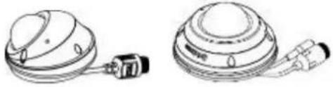 | b. Product CD | |
c. Adjusting Lens Tool (MD Series only)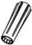 | d. Allen Key | |
e. Warranty Card | f. Screw Bags(2pcs)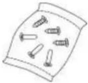 | |
g. Dry Bag / Double-Sided Tape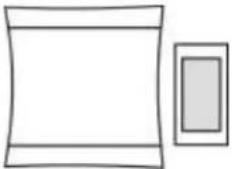 | h. Alignment Sticker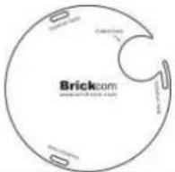 | |
i. Easy Installation Guide | j. Mounting Adapter | |
k. TV out Connector Cable (Optional)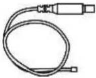 | I. RJ45 Waterproof Connector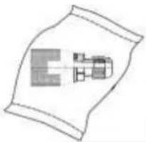 | M12(Optional)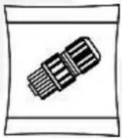 |
Brickcom
Chapter 2 - Mini Dome Network Camera Overview
The Brickcom Mini Dome Network Camera designed for outdoor use. MD series has a compact and stylish design, also provides Full HDTV video (1080p @ 30fps). IP67 certified, IK10 vandal-proof and EN50155 Anti Vibration and Shock, it is perfect for outdoor surveillance, and surveillance in buses, trains, subway cars and emergency vehicles.
The Mini Dome Network Camera series is designed to provide end users with high quality video feed for an easily accessible security system. By offering H.264/M-JPEG/MPEG-4 triple codec compression, it is able to offer a flexible system which does not require high bandwidth and storage capabilities. The internal micro SD/SDHC/SDXC memory card slot allows for local storage, which prevents data loss if the data connection is lost. The Mini Dome Network Camera 360 Series comes with a wide-angle lens and 360° Immervision Panoramic Lens and Pan 35° / Tilt 0 - 90° / Rotation 180° wide angle adjustment, allowing a wide open view for maximum coverage.
Different from other dome cameras, Mini Dome Network Camera Series supports exchangeable lenses for different conditions.
The Mini Dome Network Camera series is designed for easy installation. With the BNC TV-Out Connector, the camera can be connected to a monitor which makes it easier for installers to adjust the picture focus while setting up the camera. The MD-500A series/MD-300N series is equipped with a special designed mounting adapter and can be installed on a curved surface. The camera supports different power inputs such as PoE 802.3af, M12
and DC12Vs
![graph TD A["PoE Injector"] --> B["Network Camera"] B --> C["Web Bus"] B --> D["NVR"] B --> E["CMS"] E --> F["Internet"] F --> G["3G Network"] G --> H["Phone"] F --> I["Network Camera"] I --> J["Train"] I --> K["Vandal-proof"] I --> L["Web Browser NB/PC"] style A fill:#f9f,stroke:#333 style B fill:#c…](/content/2026/06/1187714/images/c892c50bd98175499eb2dca8e2dddd3c3eeee4211e1a6cafb38ac8a13cf2688d.jpg)
Brickcom
Chapter 3 - Device Appearance Description

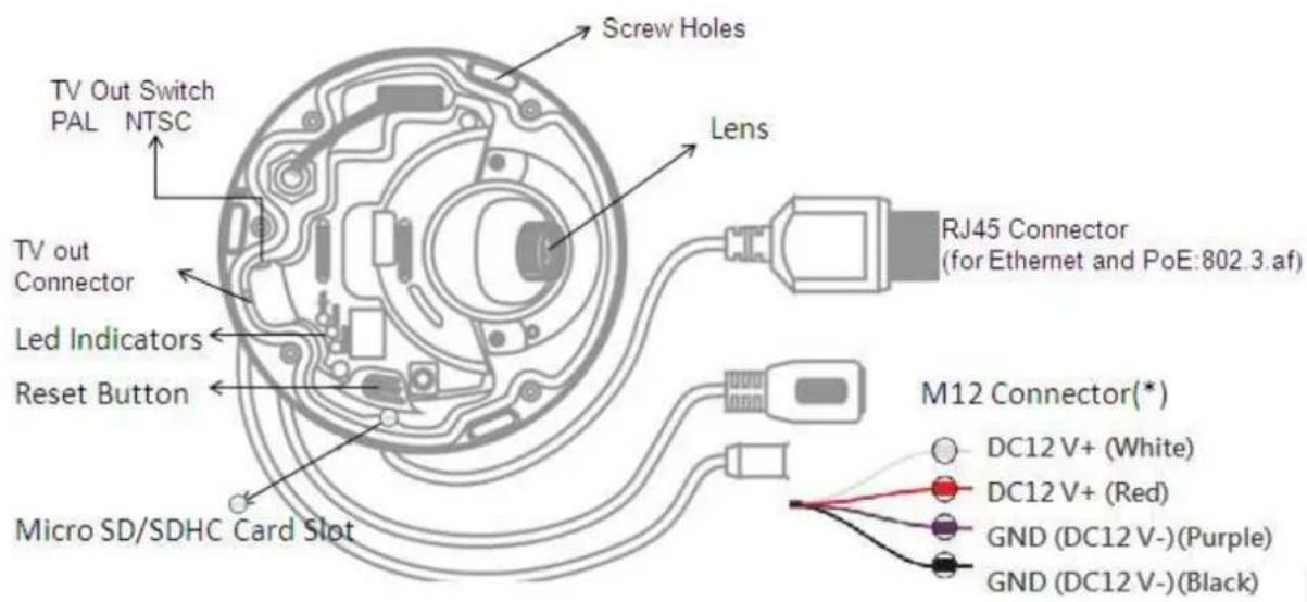

Brickcom
(*) These are optional features. Please refer to the Product List for the full list of optional features that are available for this product (About MD-500Ap-360P-AL/MD-300Np-360P-AL, please kindly refer to datasheet). Note: M12 only support POE Mode A.
Brickcom
Chapter 4 - LED Behavior
| Function | LED Behavior | Description | Remark |
| Status | Steady On | Normal Operation | Blue |
| Status | Unlit | 1. Power off2. Power on till System setup | Blue |
| Status |  | grading F/W | Blue |
| Internet | Blinking | Blinking while network connection in progress | Blue |
| Internet | Unlit | No connection | Blue |
| Power | Unlit | Power off | Blue |
Brickcom
Chapter 5 - Installation
5.1 Hardware Installation
WARNING: Do not mount the camera on a soft material. The camera may fall and be damaged.
- Use the enclosed Allen key to detach the dome cover from the camera device.

As remove the cover, please be aware of the Microphone Line.
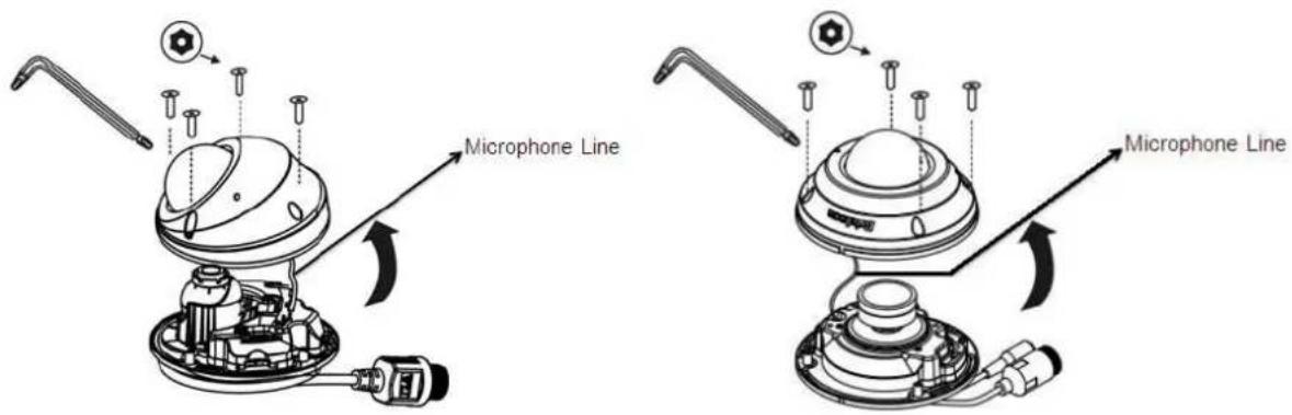
- Remove the dry bag from its package. Use the double-sided tape to stick the dry bag onto the designate position inside of the dome cover.
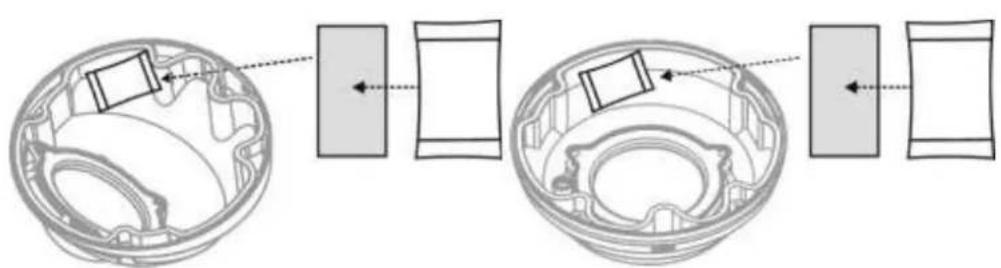
- Choose the location on the wall or ceiling to place the camera. Attach the location sticker to the desired spot. For ceiling installation, the best place to mount the camera is into a ceiling stud.
Brickcom

- Drill three holes through the center of the three location holes on the sticker.
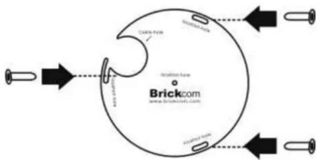
- Hammer the three plastic anchors which are provided in the product package into the three location holes.

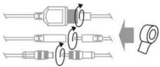
- Please use the "Waterproof Tape" to wrap around the RJ45 connector, DC12V connector, USB connector (*), in order to prevent water to seep in to the connectors. Please also see below for RJ45 waterproof connector installing instruction.
![graph TD A["Step A"] --> B["Step B"] B --> C["Step C"] C --> D["Step D"]](/content/2026/06/1187714/images/fe8351c9a11a05b2fa5042d326a57401a04e91972fe6fb331bb42a1111a5ef80.jpg)
Brickcom
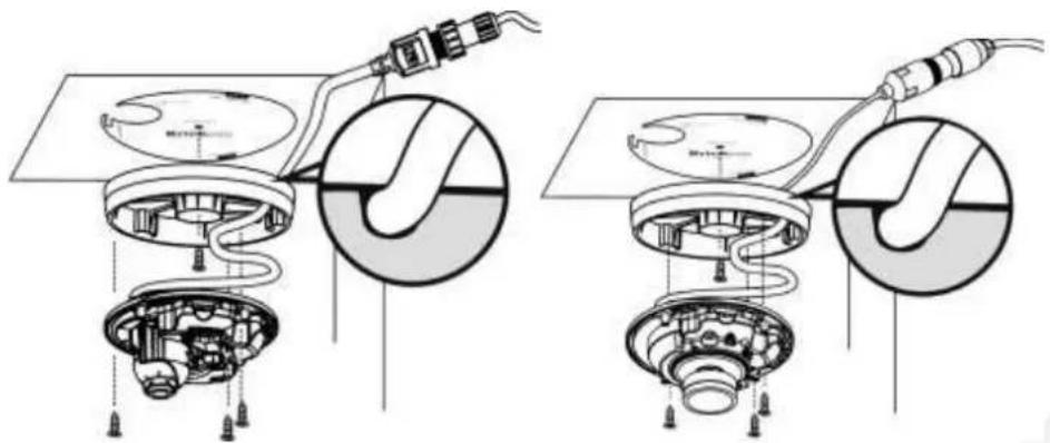
- The user needs the three screws which are included in the product package and a screwdriver. Mount the camera on the wall or ceiling and position the three screw slots over the plastic anchors. Insert the screws into the holes and use the screwdriver to tighten the screws clockwise until they are secure.

- If you use the Mounting Adapter, please use the three screws which are included in the product package and a screwdriver. Mount the camera on the wall or ceiling and position the three screw slots over the plastic anchors. Insert the screws into the holes and use the screwdriver to tighten the screws clockwise until they are secure.
Lens Adjustment
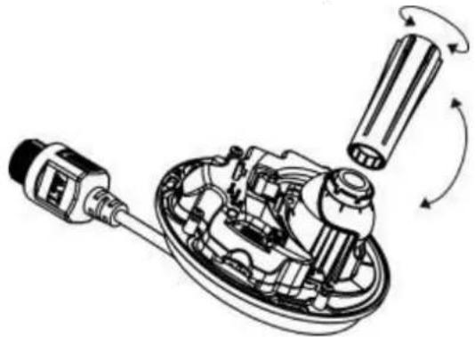
- Please use the "Adjusting Lens tool" to adjust the lens to the desired position.
Brickcom

- Focus
a. Rotate the lens until the image in the Live View page is focused.
b. Remove the tool directly.
5.2 Camera Connection
The New Mini Dome Series is DC12V and PoE compliant, so there are two options for connecting the camera to a power and Ethernet source. The camera can either be connected to a PoE-enabled switch or a non-PoE switch.
a. If using a PoE-enabled switch:
Use a single Ethernet cable to connect the camera to the PoE-enabled switch.

b. If using a non-PoE switch:
Brickcom
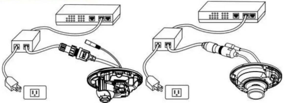
i. Use a standard RJ-45 cable to connect the camera to a PoE Injector.
ii. Use a standard RJ-45 cable to connect the PoE Injector to the non-PoE switch.
iii. Use a standard power cable to connect the PoE Injector to a power outlet.
c. If using the DC12V for the power Supply. The RJ45 cable will be data transmission.

Complete the Installation
Place the dome cover back on the camera device using the Allen Key.
Brickcom
< Hardware Reset >

The Reset Button can be used to reboot the camera or restore it to factory default settings. If the camera experiences a problem, rebooting the camera may correct the problem. If the problem remains, please restore the camera to factory default settings and reinstall the software.
To Reboot - Press and hold the Reset Button for one second using a paper clip or thin object.
Wait for the camera to reboot.
To Restore – Press and hold the Reset Button for ten seconds until the LED light turns off. When successful restored, the LED will be blue during normal operation.

NOTE: By restoring the camera, all settings will be restored to the factory default settings.
Micro-SD/SDHC/SDXC Card Capacity (*)
The network camera is compatible with Micro-SD/SDHC/SDXC (Maximum 128GB) cards.
Brickcom
5.3 How to Adjust 360P Lens (MD-500Ap/300Np-360P-AL only)
Based on the default setting, the camera is set to have a clear view for the objects at 3 meters (10 feet) away.
Step 1. Remove the Mini Dome Cover
This step applies to the 360P mini dome cameras only. Please use the enclosed Allen Key to detach the mini dome cover from the camera.


When removing the cover, please be aware of the microphone
Step 2. Unscrew the Lens
Please slowly unscrew Fixing screws of Direction & Elliptical image. Please be cautious to these tiny screws.
Step 3. Focus Adjustment
Please click "Real Size" on the control panel of Live View before focusing the image. Then, rotate the Focusing ring to get the image in focus.
Step 4. Shape Adjustment
Please click "Full Screen" on the control panel of Live View before adjusting the
Brickcom
shape of the image. Then, please hold the Focusing ring, and rotate the Aligning ring of Direction & Elliptical image to get the appropriate elliptical image.
Step 5. Position Adjustment
Please hold the Focusing ring. Then, push and pull the Aligning ring of Direction & Elliptical image to align the image position in the center of the view.
Step 6. Screw Down the Lens
Please do not screw all the way down to avoid changing the image position. First, select one of the screws, and push the Aligning ring of Direction & Elliptical image towards this screw. Then, slowly screw down until the image is in the center of the view. Please do the same thing to the second screw. Finally, please screw down the last screw.
Step 7. Put Back the Mini Dome Cover
This step applies to the 360P mini dome cameras only. Please put the mini dome cover back on the camera, and use the Allen Key to fix the cover.
Brickcom
5.4 System Requirements
Operating System:
Microsoft Windows 8.1/8/7/Vista/XP/2000
Computer:
IBM PC/AT Compatible
CPU:
Pentium 3GHz or faster
Memory:
1024 MB or more
Monitor:
1024 x 768 pixels or more, 24-bit True color or better
Network Interface:
10/100Mbps Network interface card must be installed
Web Browser:
Microsoft Internet Explorer 6.0 SP2 or higher
Adobe Reader:
Adobe Reader 8.0 or higher
Audio:
The audio function will not work if a sound card is not installed in the PC. Audio may be interrupted depending on network traffic.
Brickcom
5.5 Software Installation
In this manual, "User" refers to whoever has access to the Network Camera, and "Administrator" refers to the person who can configure the camera and grant user access to the camera.
After checking the hardware connection, run the Installation Wizard program included on the product's CDROM to automatically search the intranet for the camera. There may be many cameras on the local network. Differentiate the cameras using the serial number which is printed on the labels on the carton and the bottom of the camera.
A. Insert the Installation CD into the CD-ROM driver. Run Auto-Run Tool directly from the CD-ROM to start the installation. When installing the Brickcom software kit for the first time, select a desired language for the interface. The available languages are listed in the scroll box. Click

Brickcom
B. In the Install Shield Wizard dialog box, click

C. Read the End-User License Agreement and check the option "I accept the terms of the license agreement". Click

Brickcom
D. Select either "Complete" setup or "Custom" setup to install the system.
If COMPLETE SETUP is selected:
i. All program features will be installed into the default directory. Check the option "Complete" and then click
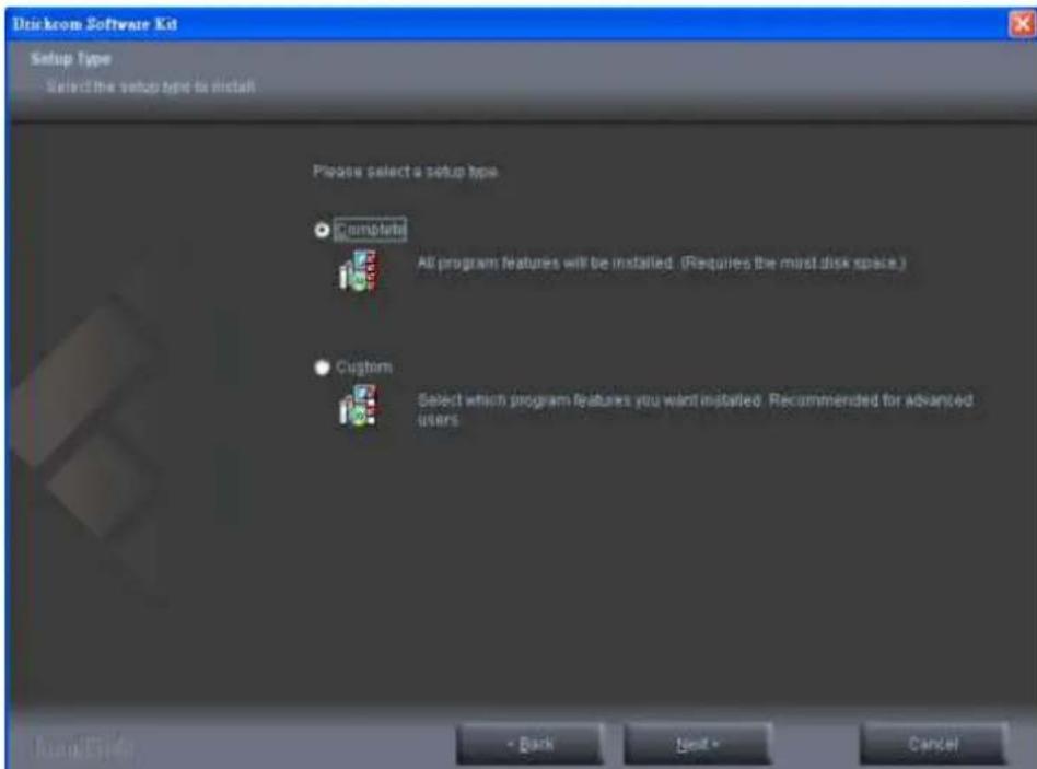
ii. Click

Brickcom
iii. Select to create shortcuts. Click
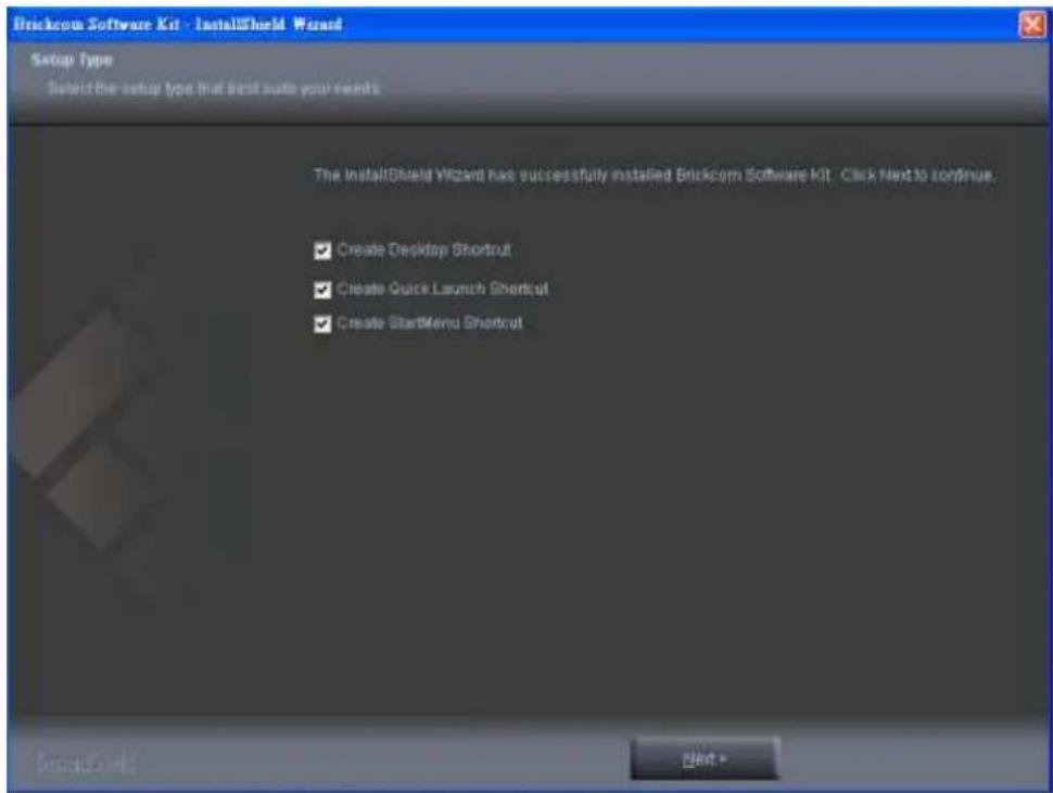
iv. The installation information will be displayed. Click
![Brickcom Software Kit - InstallShield Wizard Please read the following text. Current Settings [ Setup Type ] Complete [ Select Features ] EasyConfig PC-NVR Standard [ Choose Destination Location ] EasyConfig: C:\Program Files\Brickcom\EasyConfig PC-NVR Standard: C:\Program Files\Brickcom\PC-NVR Stan…](/content/2026/06/1187714/images/79bbadd91f6b77f8530afdb5017d0957d64de4d87acb1829a3ecb7a73f8d504a.jpg)
Brickcom
v. To launch EasyConfig or PC-NVR Standard, select the application and click
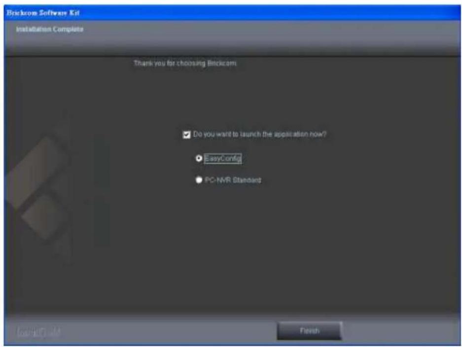
If CUSTOM SETUP is selected:
i. This option is recommended for advanced users. It can be used to install the system to a preferred directory or to select specific program feature(s).
i. Check the option "Custom", and then click

Brickcom
ii. Select the features to install. Click
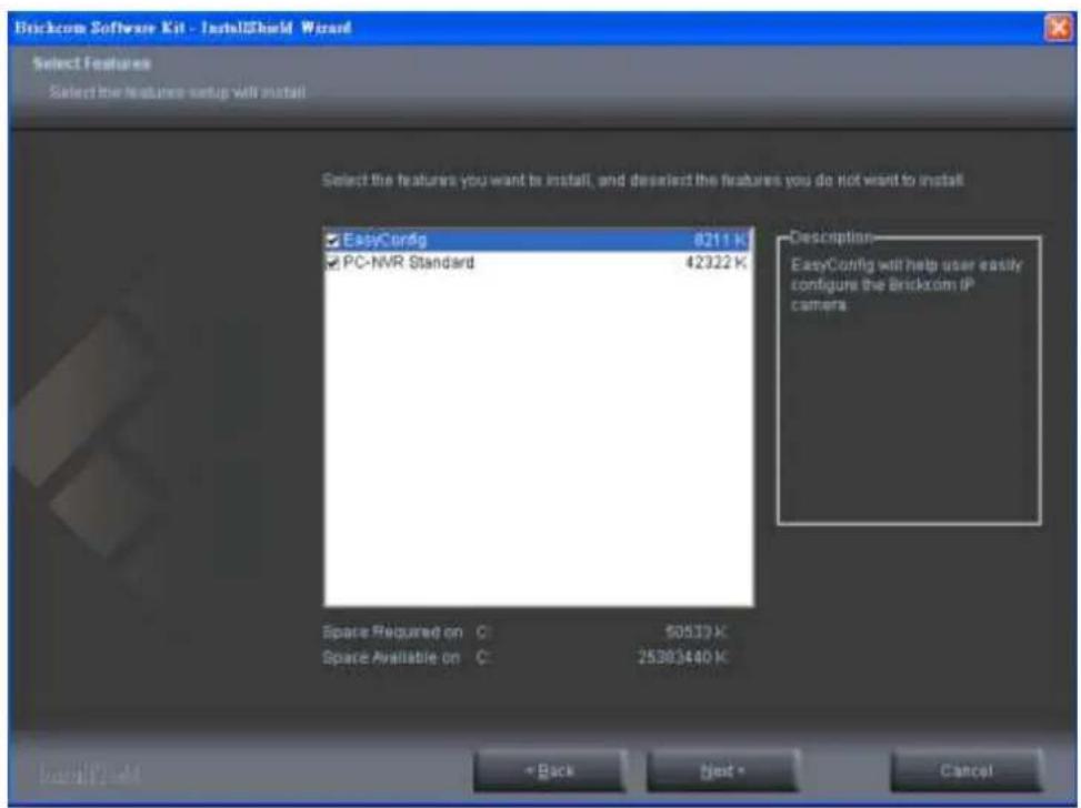
iii. Click
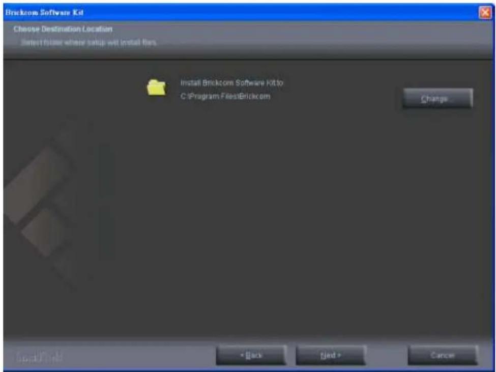
Brickcom
iv. Select programs to create shortcuts. Click
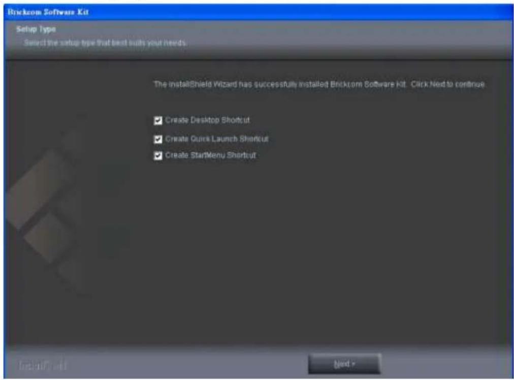
v. The installation information will be displayed. Click
![[Setup Type] Custom [Select Features] EasyConfig PC-NVR Standard [Choose Destination Location] EasyConfig: C:\Program Files\Brickcom\EasyConfig PC-NVR Standard: C:\Program Files\Brickcom\PC-NVR Standard.EXE [Creating shortcuts] EasyConfig Create Desktop Shortcut Create Quick Launch Shortcut Create S…](/content/2026/06/1187714/images/7f00bd394ba2e7cc0ee0df939546129cfba012c0f33b7b12f6f43004267005c4.jpg)
Brickcom
To launch EasyConfig or PC-NVR Standard, select the application and click

Brickcom
5.5.1 EasyConfig
To launch EasyConfig, select EasyConfig from the start menu. If Complete Setup type was used in the software installation, an EasyConfig icon was installed on the desktop. Double click to open the icon.

If Custom Setup type was used in the software installation and an EasyConfig icon was not installed on the desktop, the program will be installed under C:\Program Files\Brickcom\EasyConfig unless the program was saved to a preferred directory.
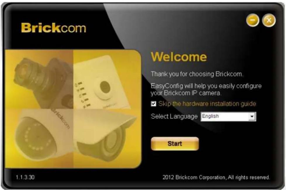
A. Click
NOTE - Check "Skip the hardware installation guide" to skip checking the hardware connection. To check the hardware installation settings, do not check the option box.
Brickcom

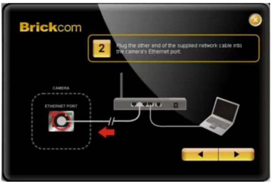
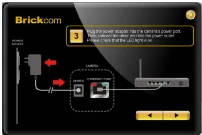
Brickcom
B. Select either "Simple Mode" or "Professional Mode" to obtain the camera's IP settings. If "Simple Mode" is selected, EasyConfig will set up the connection automatically. If "Professional Mode" is selected, the user will need to configure the IP settings manually.
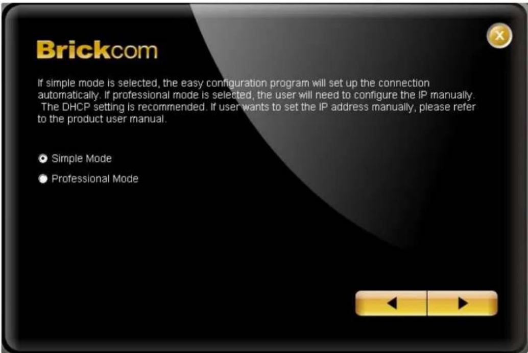
C. There may be many cameras in the local network. Differentiate the cameras using their UPnP name. Double click on the camera from the survey list to connect.
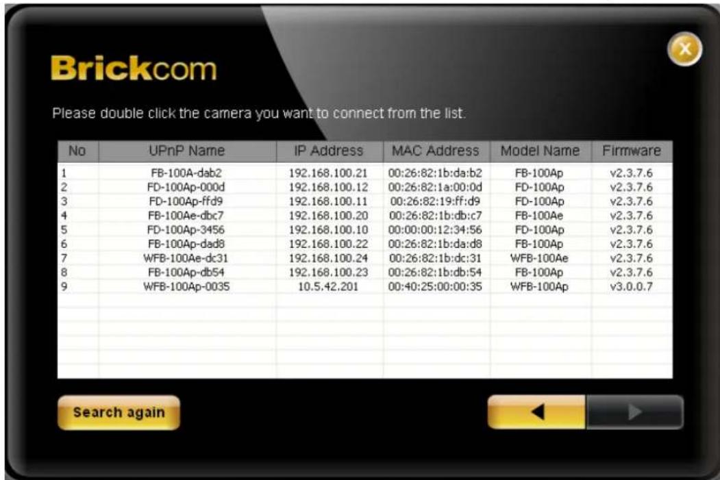
D. Enter the username and password of the camera. For first time use, the default
Brickcom
username and password are "admin/admin."
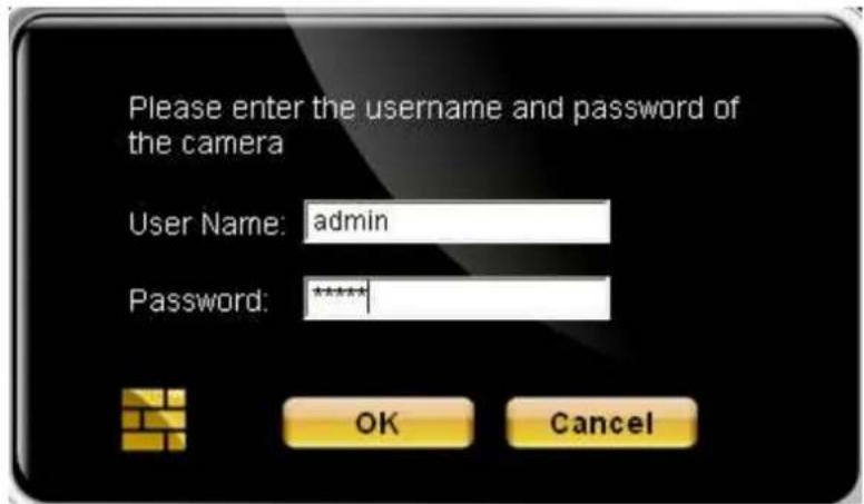
E. For configuring the IP address settings, select either

Brickcom
If
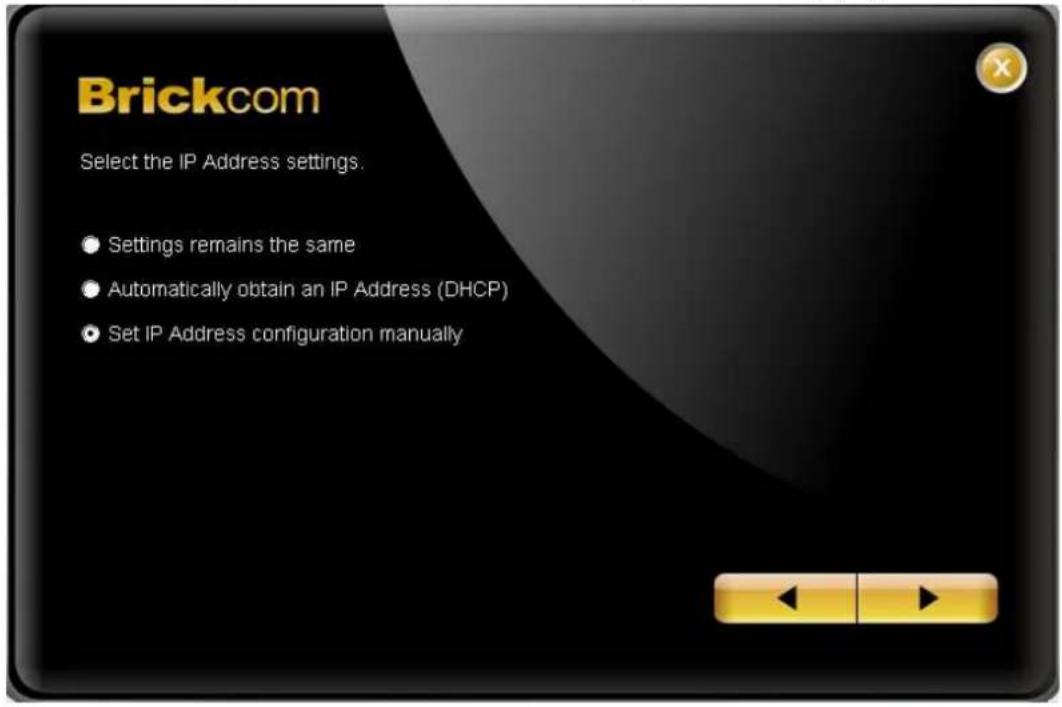
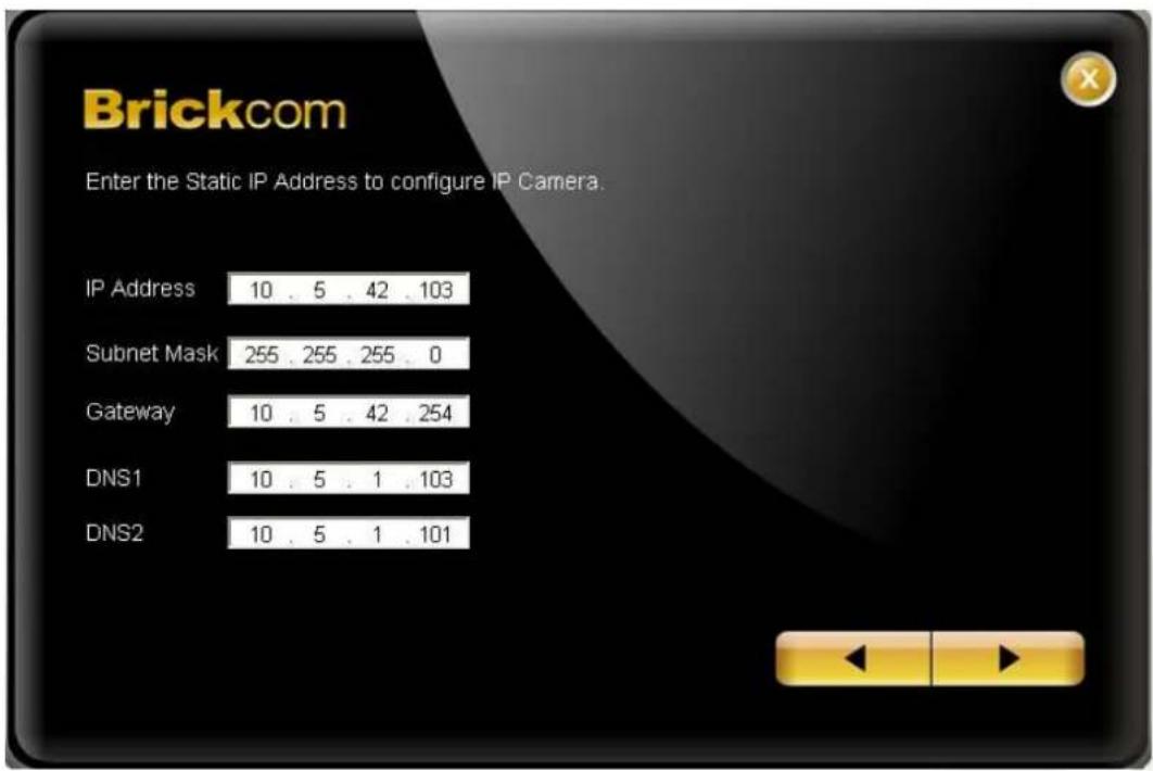
Brickcom
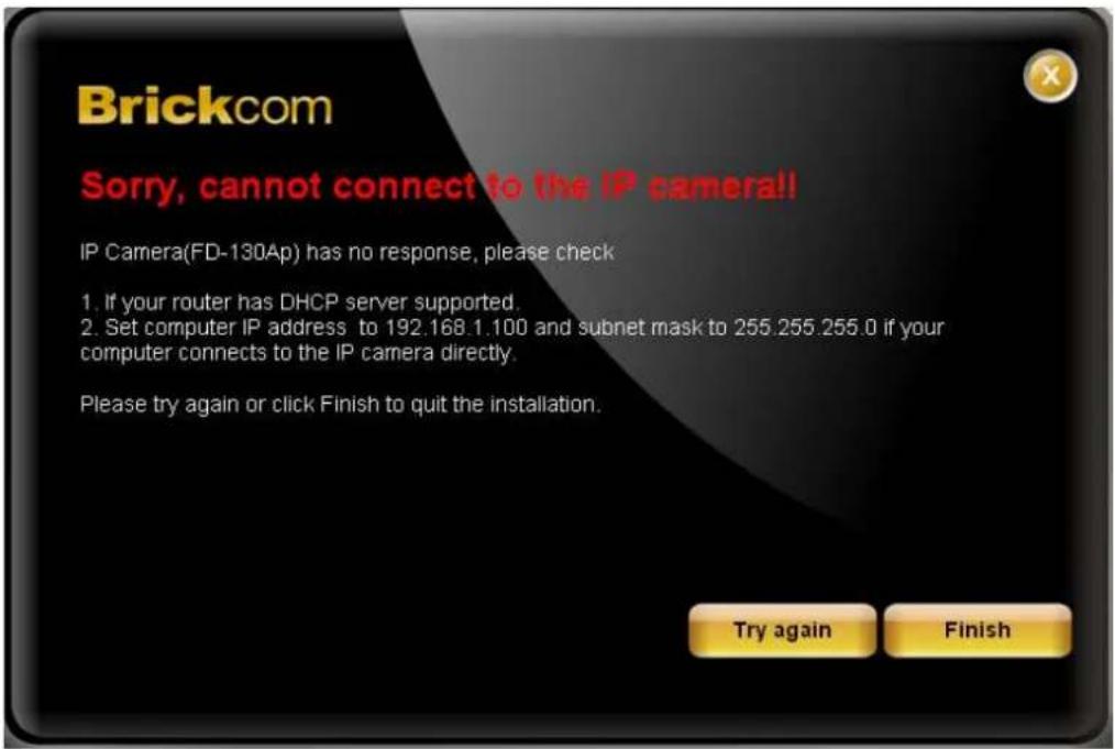
F. When the IP address settings have been configured, the screen will either display a successful or failed connection message. If the connection failed, either try again or quit the installation.
a. If "DHCP IP address settings" was selected, the failure page will be displayed as below:
b. If "Static IP address settings" was selected, the failure page will be displayed as below:

Brickcom
c. If the connection was successful, the user will see the message:
"Congratulations. The installation of the camera is complete."
When this window is displayed, click

Once installation is complete, the Administrator should proceed to the next section "Accessing the Network Camera" for necessary changes and configurations.
- HARDWARE USER'S MANUAL
- BRICKCOM
- TABLE OF CONTENTS
- BEFORE YOU USE THIS PRODUCT
- REGULATORY INFORMATION
- FEDERAL COMMUNICATION COMMISSION INTERFERENCE STATEMENT
- IMPORTANT NOTE
- FCC RADIATION EXPOSURE STATEMENT
- CHAPTER 1 - PACKAGE CONTENTS
- CHAPTER 2 - MINI DOME NETWORK CAMERA OVERVIEW
- CHAPTER 3 - DEVICE APPEARANCE DESCRIPTION
- CHAPTER 4 - LED BEHAVIOR
- CHAPTER 5 - INSTALLATION
- 5.1 HARDWARE INSTALLATION
- LENS ADJUSTMENT
- 5.2 CAMERA CONNECTION
- IF USING A POE-ENABLED SWITCH
- COMPLETE THE INSTALLATION
- MICRO-SD/SDHC/SDXC CARD CAPACITY (*)
- 5.3 HOW TO ADJUST 360P LENS (MD-500AP/300NP-360P-AL ONLY)
- STEP 1. REMOVE THE MINI DOME COVER
- STEP 2. UNSCREW THE LENS
- STEP 3. FOCUS ADJUSTMENT
- STEP 4. SHAPE ADJUSTMENT
- STEP 5. POSITION ADJUSTMENT
- STEP 6. SCREW DOWN THE LENS
- STEP 7. PUT BACK THE MINI DOME COVER
- 5.4 SYSTEM REQUIREMENTS
- OPERATING SYSTEM
- COMPUTER
- CPU
- MEMORY
- MONITOR
- NETWORK INTERFACE
- WEB BROWSER
- ADOBE READER
- AUDIO
- 5.5 SOFTWARE INSTALLATION
- IF COMPLETE SETUP IS SELECTED
- IF CUSTOM SETUP IS SELECTED
- 5.5.1 EASYCONFIG
Brand : Brickcom
Model : MD-300NP STAR
Category : Security Camera