
DS-PAN-214-2 - Computer accessory Havis - Free user manual and instructions
Find the device manual for free DS-PAN-214-2 Havis in PDF.

| Product Type | Weatherproof Docking Station for Panasonic CF-19 Toughbook |
| Brand | Havis |
| Model | DS-PAN-214-2 |
| Compatibility | Panasonic CF-19 Toughbook |
| IP Rating | IP65 |
| Port Replication | Supports VGA, USB, network, and other connections via cable routing |
| Maximum Cable Diameter | 0.315 in (8.00 mm) |
| Cable Cover Capacity | Up to 6 cables |
| Antenna Cable Routing | Yes (for DS-PAN-214-2 model) with push pin zip ties |
| Mounting Bracket | Included |
| Additional Parts Included | Cable cover, docking connector cover with thumb screws, 8-32 screws (7), grommets (7), grommet plugs (7), zip ties (7), foam tape |
| Hardware Kit | DS-PAN-210 Series Owner's Manual & Hardware Kit (zip ties, keys, 1/4-20 screws, M5 screws) |
| Maintenance | Regularly remove excess moisture and contaminants from external surfaces, especially lock, docking connector, and cable connectors |
| Safety Precautions | Read all instructions before installation; do not mate computer unless docking connector door is fully open; always use docking connector cover when not in use |
| Torque Specs | 8-32 screws tightened to 20 ± 10% in-lbs |
| Customer Support | Contact Havis at 1-800-524-9900 or www.havis.com |
Frequently Asked Questions - DS-PAN-214-2 Havis
User questions about DS-PAN-214-2 Havis
0 question about this device. Answer the ones you know or ask your own.
Ask a new question about this device
Download the instructions for your Computer accessory in PDF format for free! Find your manual DS-PAN-214-2 - Havis and take your electronic device back in hand. On this page are published all the documents necessary for the use of your device. DS-PAN-214-2 by Havis.
USER MANUAL DS-PAN-214-2 Havis
Installation Instructions Havis Weatherproof Docking Station For Panasonic CF-19 Toughbook
This document is a supplement to the supplied Owner's Manual, and applies only to installation and use of the IP65 compliant DS-PAN-214 & DS-PAN-214-2 Docking Stations for the Panasonic CF-19 laptop computer.
For questions regarding the set-up of your DS-PAN-214 or DS-PAN-214-2 Docking Station, please contact Havis at 1-800-524-9900 or visit www.havis.com for additional product support and information.
This Supplement applies to the following Part Numbers: DS-PAN-214DS-PAN-214-2
CAUTION
- READ ALL INSTRUCTIONS THOROUGHLY BEFORE BEGINNING INSTALLATION.
- DO NOT MATE COMPUTER TO DOCKING STATION UNLESS COMPUTER'S DOCKING CONNECTOR ACCESS DOOR IS FULLY OPEN OR DAMAGE MAY RESULT.
- ALWAYS USE DOCKING CONNECTOR COVER WHEN DOCKING STATION IS NOT IN USE.
• TO MAXIMIZE THE LIFE OF YOUR PRODUCT, IT MAY BE NECESSARY TO ROUTINELY REMOVE EXCESS MOISTURE OR CONTAMINANTS FROM THE DOCKING STATION EXTERNAL SURFACES, ESPECIALLY THE LOCK AND REGIONS SURROUNDING THE DOCKING CONNECTOR AND CABLE CONNECTORS.
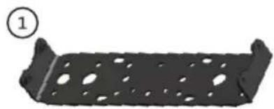
Additional Parts
- Mounting Bracket (1)
- Cable Cover (1)
- Docking Connector Cover (1) with Thumb Screws
-
8-32 Pan Head Phillips Screws (7)
- Grommets (7)
- Grommet Plugs (7)
- Zip Ties (7)
- Foam Tape
- DS-PAN-210 Series Owner's Manual & Hardware Kit (not shown)
Includes: Zip Ties (4), Keys (2), 1/4"-20 Screws (3), M5 Screws (4)
natural_image
Metallic rectangular component with perforated holes and a curved base (no text or symbols)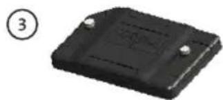
natural_image
Black rectangular electronic component with two small pins, labeled with number 3 (no text or symbols on the body)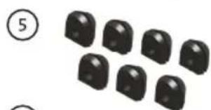
natural_image
Group of black rounded objects arranged in rows, no text or symbols visible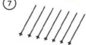
natural_image
Pure diagram of parallel lines with arrows, no text or symbols present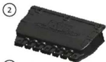
natural_image
Close-up of a black integrated circuit chip with pins, labeled with number 2 (no text or symbols on the chip itself)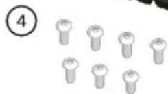

natural_image
Simple gray diagonal line with a circled number 8 in the top-left corner (no text or symbols on the line itself)Port Replication
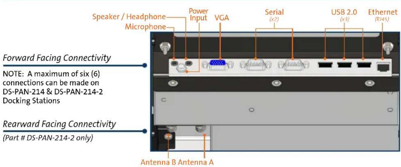
NOTICE
The following instructions are meant to take the place of the 'Installation' and 'Cable Management' sections of the Owner's Manual (Pages 4-6). Please read all included instructions thoroughly before beginning installation.
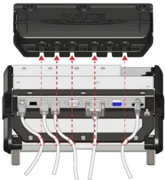
1). Place Docking Station top side down on a stable surface and connect all necessary cables needed for operation.
NOTE: Do not exceed a cable diameter of 0.315" (8.00 mm)
natural_image
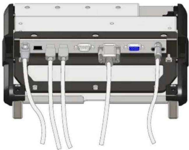
Back view of a computer chassis showing internal components including VGA, USB, and network cables (no text or labels visible)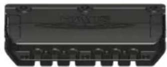
natural_image
Close-up of a black electronic component with multiple pins and a central display (no visible text or symbols)NOTE: Only six (6) total cables can be routed through the Cable Cover.
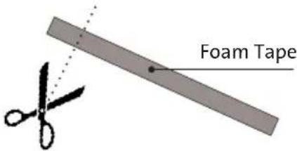
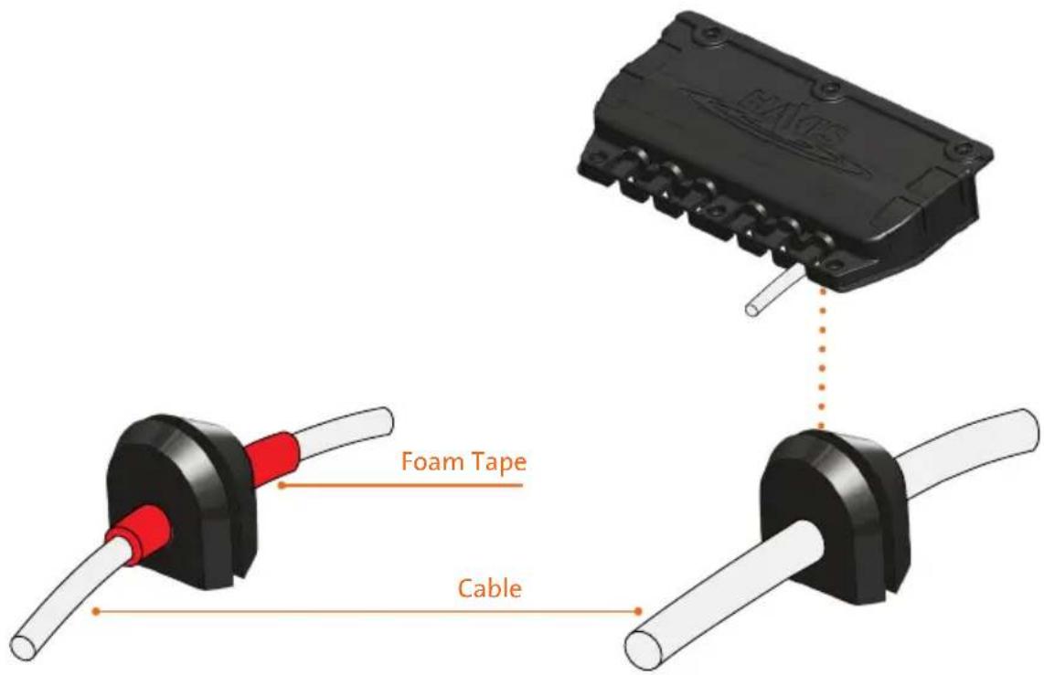
2). With all cables connected, determine the optimal routing of cables to the Cable Cover exits, taking care to avoid cable obstructions. For all cables with a diameter less than 0.25" (6.0 mm), cut small strips of supplied Foam Tape to wrap around cables to enlarge the diameter to the optimal 0.25". Ensure the Foam Tape is positioned at the determined exit point from Cable Cover.
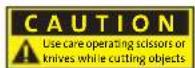

3). For each exiting cable, use a sharp knife or scissors to cut through the center of a rubber Grommet in order to insert the cable into Grommet hole. (Fig. A) DO NOT CUT GROMMETS FOR CABLE COVER EXITS WITHOUT EXITING CABLES. Instead, add a Grommet Plug and insert Grommet into the Cable Cover in the orientation shown. (Fig. B)
Fig. A: Cut Grommet to accept cable
Fig. B: Plug un-cut Grommet

4). Secure the cut Grommet around cable or Foam Tape in the position identified in Step 2. Insert Grommets with cables intact into the appropriate cable exits in the Cable Cover, taking care to not pinch cables. Use a Grommet with Grommet Plug for all exits not occupied with a Grommet and cable.
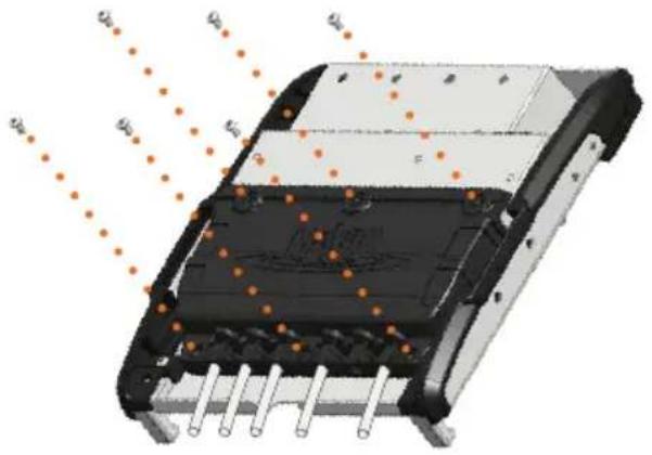
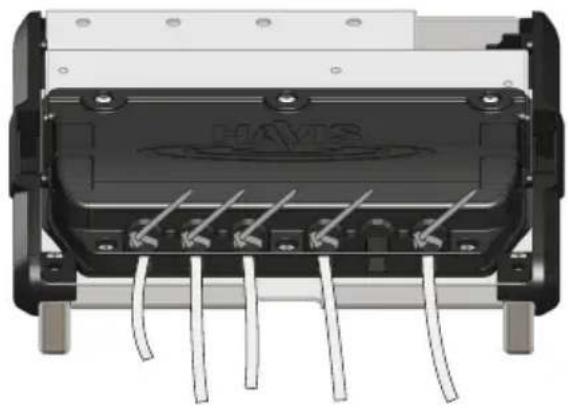
5). Lower Cable Cover into place on Docking Station, making sure all six cable exits have a Grommet with cable inserted, or a Grommet with Grommet Plug inserted. Fasten #8-32 Pan Head Phillips Screws in 6 places as shown. Torque all six #8-32 Pan Head Phillips Screws to 20 ± 10% in-lbs.
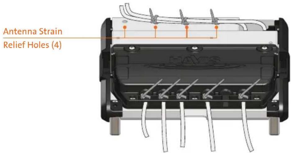
6). Insert Zip Ties into strain relief holes on the Cable Cover in order to secure exiting cables. Cut off excess from connected Zip Ties. Ensure that Zip Tie is routed beneath cable for adequate strain relief.
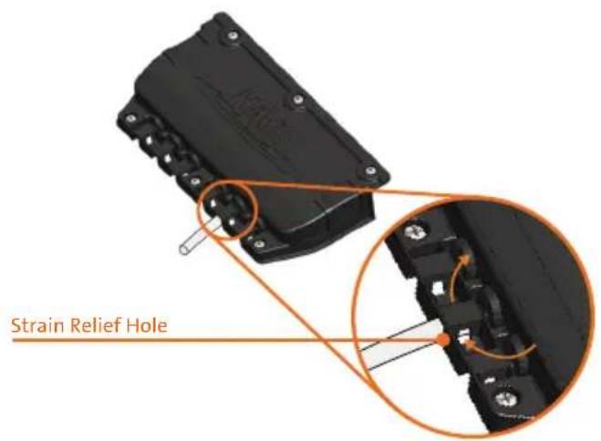
natural_image
Close-up of an electronic component with visible pins and wiring (no text or symbols)If you are routing Antenna cable(s) (Part # DS-PAN-214-2), use Push Pin Zip Ties supplied with the Docking Station Hardware Kit to secure the cable(s) to the Strain Relief Holes at the back of the Docking Station. Then route the cables to the cable bundle and secure as specified in the Owner's Manual (Page 6, Step 5).
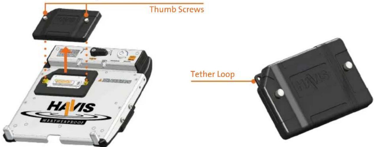
1). Taking care to remove any excess moisture which may be present, remove Docking Connector Cover by unscrewing the two thumb screws. Use the Tether Loop if desired to attach Docking Connector Cover to a fixed object. (Tether not included) If Tether option is not used, store Docking Connector Cover in a safe, dry location.
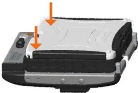
2). Follow Docking and Undocking instructions in the Owner's Manual (Pages 7-8), making sure to apply downward pressure to the computer while latching in order to sufficiently compress the Gasket surrounding the Docking Connector.
natural_image
Close-up of a mechanical device with orange arrows pointing to features, no visible text or symbols3). Taking care once again to remove any excess moisture from the computer and Docking Station, Undock the computer according to the Owner's Manual (Page 8) and lower the Docking Connector Cover on the Docking Station. Hand tighten the two thumb screws.


Havis, Inc.
75 Jacksonville Road, PO Box 2099
Warminster, PA 18974
47801 Anchor Court
Plymouth, MI 48170
www.havis.com 1-800-524-9900


Brand : Havis
Model : DS-PAN-214-2
Category : Computer accessory