
VE157 - AV Switch ATEN - Free user manual and instructions
Find the device manual for free VE157 ATEN in PDF.


| Product Type | VGA/DVI/HDMI Audio Cat 5 Extender with MK Wall Plate |
| Model | VE157 |
| Brand | ATEN |
| Video Input | 1 x HDB-15 Female (VGA) |
| Video Output | 1 x HDB-15 Female (VGA) |
| Audio Input | 1 x 3.5mm Stereo Jack (Green) |
| Audio Output | 1 x 3.5mm Stereo Jack (Green) |
| Connection Cable | Two Cat 5e cables (one for video/audio, one for power) |
| Maximum Distance | Up to 150 m (1280 x 1024 @ 60Hz) |
| Supported Resolutions | 1920 x 1200 @ 60Hz (30 m), 1280 x 1024 @ 60Hz (150 m) |
| Video Adjustment | Manual Gain Control knob (for distance compensation) |
| Power Supply | DC 9V, 3.2W via Terminal Block and included Power Adapter |
| Power Source | Remotely powered from either Transmitter or Receiver using second Cat 5e |
| LED Indicators | Power (Green), Link (Amber) |
| ESD Protection | Built-in 8KV/15KV |
| Hot-Plugging | Supported |
| Dimensions (L x W x H) | 10.41 x 4.40 x 4.40 cm |
| Weight | 0.17 kg (each unit) |
| Housing | Metal |
| Operating Temperature | 0–50°C |
| Storage Temperature | -20–60°C |
| Humidity | 0–80% RH, Non-condensing |
| Package Contents | Transmitter, Receiver, Terminal Block Connector, Power Adapter, 2 x Wall Plate Covers, 8 x Screw Covers, Screw Kit, User Instructions |
| Mounting | Wall plate mountable (fits standard 1-gang wall box, min depth 4.5 cm) |
| Compliance | FCC Class A, CE, RoHS |
| Cleaning | Unplug before cleaning; use a damp cloth. Do not use liquid or aerosol cleaners. |
| Spare Parts Availability | Power adapter available from ATEN or authorized dealers; Cat 5e cables and VGA/audio cables not included but standard. |
Frequently Asked Questions - VE157 ATEN
User questions about VE157 ATEN
0 question about this device. Answer the ones you know or ask your own.
Ask a new question about this device
Download the instructions for your AV Switch in PDF format for free! Find your manual VE157 - ATEN and take your electronic device back in hand. On this page are published all the documents necessary for the use of your device. VE157 by ATEN.
USER MANUAL VE157 ATEN
natural_image
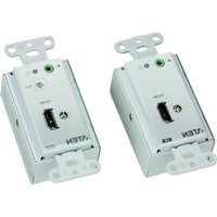
White ATEN device with HDMI port and ports (no readable text or symbols beyond branding)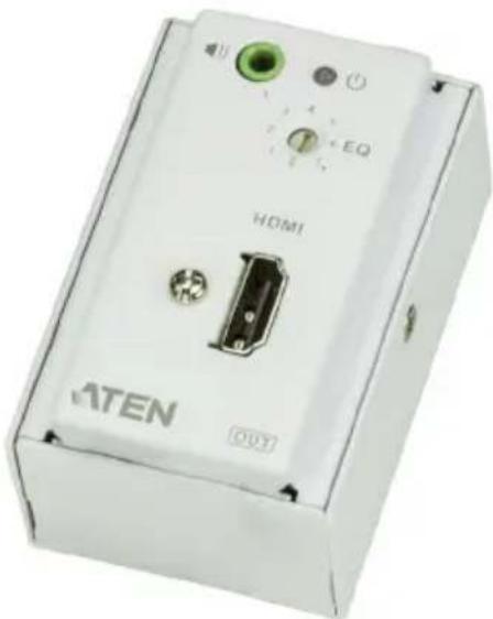
natural_image
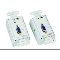
White electronic device labeled 'HDMI' with green and black ports, no visible text or symbols beyond brandingHDMI TM
HIGHDEFRITION MULTIMEDIA INTERFACE
EMC Information
FEDERAL COMMUNICATIONS COMMISSION INTERFERENCE STATEMENT: This equipment has been tested and found to comply with the limits for a Class A digital device, pursuant to Part 15 of the FCC Rules. These limits are designed to provide reasonable protection against harmful interference when the equipment is operated in a commercial environment. This equipment generates, uses, and can radiate radio frequency energy and, if not installed and used in accordance with the instruction manual, may cause harmful interference to radio communications. Operation of this equipment in a residential area is likely to cause harmful interference in which case the user will be required to correct the interference at his own expense.
This device complies with Part 15 of the FCC Rules. Operation is subject to the following two conditions: (1) this device may not cause harmful interference, and (2) this device must accept any interference received, including interference that may cause undesired operation.
FCC Caution: Any changes or modifications not expressly approved by the party responsible for compliance could void the user's authority to operate this equipment.
Warning: Operation of this equipment in a residential environment could cause radio interference.
Suggestion: Shielded twisted pair (STP) cables must be used with the unit to ensure compliance with FCC & CE standards.
This product is RoHS compliant.

© Copyright 2021 ATEN® International Co., Ltd. Released Date: 2021-01-14
ATEN and the ATEN logo are registered trademarks of ATEN International Co., Ltd. All rights reserved. All other brand names and trademarks are the registered property of their respective owners. The terms HDMI, HDMI High-Definition Multimedia Interface, and the HDMI Logo are trademarks or registered trademarks of HDMI Licensing Administrator, Inc.
User Information
Online Registration
Be sure to register your product at our online support center:
| International http://eservice.aten.com |
Telephone Support
For telephone support, call this number:
| International 886-2-8692-6959 |
| China 86-400-810-0-810 |
| Japan 81-3-5615-5811 |
| Korea 82-2-467-6789 |
| North America 1-888-999-ATEN ext 4988 |
| 1-949-428-1111 |
User Notice
All information, documentation, and specifications contained in this manual are subject to change without prior notification by the manufacturer. The manufacturer makes no representations or warranties, either expressed or implied, with respect to the contents hereof and specifically disclaims any warranties as to merchantability or fitness for any particular purpose. Any of the manufacturer's software described in this manual is sold or licensed as is. Should the programs prove defective following their purchase, the buyer (and not the manufacturer, its distributor, or its dealer), assumes the entire cost of all necessary servicing, repair and any incidental or consequential damages resulting from any defect in the software.
The manufacturer of this system is not responsible for any radio and/or TV interference caused by unauthorized modifications to this device. It is the responsibility of the user to correct such interference.
The manufacturer is not responsible for any damage incurred in the operation of this system if the correct operational voltage setting was not selected prior to operation. PLEASE VERIFY THAT THE VOLTAGE SETTING IS CORRECT BEFORE USE.
Package Contents
The VGA/DVI/HDMI Audio Cat 5 Extender with MK Wall Plate package contains the following items:
◆ 1 VE157T / VE607T / VE807T VGA/DVI/HDMI Audio Cat 5 Extender with MK Wall Plate
◆ 1 VE157R / VE607R / VE807R VGA/DVI/HDMI Audio Cat 5 Extender with MK Wall Plate
◆ 1 Terminal Block Connector
◆ 1 Power Adapter
◆ 2 MK type Wall Plate Covers
♦ 8 Screw Covers
◆ 1 Screw kit
◆ 1 User Instructions*
Check to make sure that all the components are present and that nothing got damaged in shipping. If you encounter a problem, contact your dealer.
Read this manual thoroughly and follow the installation and operation procedures carefully to prevent any damage to the unit, and/or any of the devices connected to it.
Contents
EMC Information....ii
RoHS.ii
User Information ....iii
Online Registration .....iii
Telephone Support .....iii
User Notice ....iii
Package Contents.... iv
About this Manual ...... vi
Conventions vii
Product Information....vii
1. Introduction
Overview 1
Features 2
Requirements 3
Console....3
Computer....3
Cables....3
Components 4
Front View (Transmitter) 4
Front View (Receiver) 4
Rear View (Transmitter / Receiver) 5
2. Hardware Setup
Overview 7
Wall Plate Dimensions....7
How to Supply Power 8
Wall Mounting 10
Hardware Installation 11
3. Basic Operation
Overview 13
Picture Adjustment ....13
Appendix
Safety Instructions....15
General 15
Technical Support....17
International....17
North America 17
Supported ATEN Products 18
Specifications 19
Limited Warranty....41
About this Manual
This User Manual is provided to help you get the most from your system. It covers all aspects of installation, configuration and operation. An overview of the information found in the manual is provided below.
Chapter 1, Introduction, introduces you to the VE157 / VE607 / VE807 system. Its purpose, features and benefits are presented, and its front and back panel components are described.
Chapter 2, Hardware Setup, describes how to set up your installation. All necessary steps to prepare for operation are provided.
Chapter 3, Basic Operation, describes how to adjust the picture quality.
An Appendix, provides specifications and other technical information regarding the VE157 / VE607 / VE807.
Conventions
This manual uses the following conventions:
Monospaced Indicates text that you should key in.
[] Indicates keys you should press. For example, [Enter] means to press the Enter key. If keys need to be chorded, they appear together in the same bracket with a plus sign between them: [Ctrl+Alt].
- Numbered lists represent procedures with sequential steps.
◆ Bullet lists provide information, but do not involve sequential steps.
→Indicates selecting the option (on a menu or dialog box, for example), that comes next. For example, Start → Run means to open the Start menu, and then select Run.

Indicates critical information.
Product Information
For information about all ATEN products and how they can help you connect without limits, visit ATEN on the Web or contact an ATEN Authorized Reseller. Visit ATEN on the Web for a list of locations and telephone numbers:
International http://www.aten.com
North America http://www.aten-usa.com
This Page Intentionally Left Blank
Overview
The VGA/DVI/HDMI Audio Cat 5 Extender with MK Wall Plate extends VGA/DVI/HDMI and audio signals up to 150 m (for VE157) / 60 m (for VE607/VE807) using Cat 5e cables. It supports popular wide screen formats and ensures excellent video quality over long distance transmissions. The VE157 / VE607 / VE807, in combination with other ATEN devices such as VGA/DVI/HDMI extenders and MDS solutions, can further extend the distance or multiply A/V sources/displays.
The VE157 / VE607 / VE807 can be powered at either the Transmitter or Receiver side, and uses a second Cat 5e cable to transmit the power signal to the other unit. The compact wall plate design does away with bulky cables and allows a neat and convenient installation. It is an ideal solution for function rooms, museums and any environment that requires equipment or cabling to be kept hidden from public view.
Features
- Uses two Cat 5e cables to connect the local and remote units – one to transmit video and audio; and another for power 1
♦ Remotely powered from either the Transmitter or Receiver side 2 - Extends the distance between VGA/DVI/HDMI source and VGA/DVI/HDMI display
- Superior video quality – VE157: up to 1920 x 1200 @60Hz (30 m), 1280 x 1024 @ 60Hz (150m); VE607 / VE807: 1080p @ 60Hz (40m), 1080i @ 60Hz (60m)
- Adjustable Video Compensation Control – manually adjusts signal strength to compensate for distance (VE157)
- 8-segment equalization adjustment switch optimizes display quality (VE607 / VE807)
- Compatible with existing ATEN VGA/DVI/HDMI extenders – see page 18 for more information
◆ Supports wide screen formats
◆ Supports hot-plugging
♦ HDMI (3D, Deep Color); HDCP compatible (VE807)
◆ LED indication of power sources / connection status
◆ Supports stereo audio
◆ Built-in 8KV/15KV ESD protection
◆ A neat and cleaner installation via easy wall-mounting
◆ Plug-and-play – no software installation required
Note: 1. The second Cat 5e cable connection is required to remotely power on either the Transmitter or Receiver.
- A power adapter is provided with this package, and can be used at either the Transmitter or Receiver side, which in turn remotely powers the other unit. See How to Supply Power, page 8.
Requirements
Console
◆ A display with an HDB-15 Male connector (for VE157)
◆ A display with an DVI Male connector (for VE607)
◆ A display with an HDMI Male connector (for VE807)
Speakers (optional)
Computer
◆ Video source with an HDB-15 Male connector (for VE157)
◆ Video source with an DVI Male connector (for VE607)
◆ Video source with an HDMI Male connector (for VE807)
◆ Audio port (optional)
Cables
- Cat 5e cables
♦ VGA / DVI / HDMI cable(s)
◆ Audio cable (optional)
Note: No cables are included in this package. It is strongly recommended that you purchase high-quality cables of the required lengths to ensure the quality of the audio and video display. Contact your dealer for more information about the correct cable sets.
Components
Front View (Transmitter)
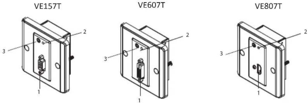
No. Component Description
| 1 Video IN Port The cable | from your VGA / DVI / HDMI source device is plugged in here. |
| 2 Power LED The Power L | LED lights green to indicate that the unit is receiving power. |
| 3 Audio IN Port | The cable from your audio source device is plugged in here. |
Front View (Receiver)

No. Component Description
| 1 Video OUT Port The cable | from your VGA / DVI / HDMI monitor plugs in here. |
| 2 Power/Link LED The Power | LED lights green to indicate that the unit is receiving power.The Link LED lights orange to indicate that the connection to the Transmitter unit has been established. |
| 3 Audio OUT Port The cable | from your speakers plugs in here. |
| 4 Manual Gain Control (VE157) / EQ Switch (VE607 / VE807) | Use this knob to adjust the video quality by turning to the right or left until you obtain the desired picture quality.See Picture Adjustment, page 13 for more details. |
Rear View (Transmitter / Receiver)

| No. | Component Description | |
| 1 Line | IN/OUT (VE157)TMDS Port (VE607 / VE807) | The Cat 5e cable that connects the Transmitter and Receiver units plugs in here. The Cat 5e connection between these ports transmits video and audio signals.For VE157:♦ Transmitter (Line OUT)♦ Receiver (Line IN) |
| 2 Power | (Terminal block) The power | adapter wires (+9V and GND) plug in here.See How to Supply Power, page 8 for the steps on how to connect the terminal block to a power source. |
| 3 Power | Port (VE157)DDC Port (VE607 / VE807) | Use a Cat 5e cable to connect the Transmitter and Receiver units through this port.The second Cat 5e cable connection transmits the power signal to either the Transmitter or Receiver when only one of the units is supplied power via the Terminal Block.For VE607 / VE807, in addition to transmitting the power signal, the second Cat 5e cable is used for real EDID Bypass and HDCP key authentication. |
| 4 Grounding | Terminal The grounding | wire is attached here.Note: The grounding wire is not included in this package. |
This Page Intentionally Left Blank
Chapter 2
Hardware Setup

-
Important safety information regarding the placement of this device is provided on page 15. Please review it before proceeding.
-
Make sure that the power to all devices connected to the installation is turned off. You must unplug the power cords of any computers that have the Keyboard Power On function.
Overview
For convenience and flexibility, the VE157 / VE607 / VE807 can be mounted on the wall, ceiling, floor or any surface of your preference.
The dimensions of the VE157 / VE607 / VE807 are made to fit an area equal to a standard wall plate.
For a neat finish, use the Wall Plate Covers that are included in the package contents. For more information on the dimensions of the VE157 / VE607 / VE807 fitted to a wall plate, see page 22.
Note: This chapter uses the VE807 panels for illustrating the installation steps.
Before Mounting
In order to mount the VE157 / VE607 / VE807, you first need to complete the following instructions:
Prepare two installation sites (for the Transmitter and Receiver units) with the proper dimensions (see image below) to accommodate the Wall Plate.
Make sure proper cabling (unit-to-unit via Cat 5e; unit-to-power) can be supplied to both sites.
Wall Plate Dimensions
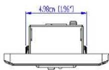
The installation site or wall plate should have a minimum depth measurement of 4.5 cm (1.77 in.). For more information, see page 22.
How to Supply Power
One pair of Power Adapter and Terminal Block Connector is provided in this package, and can be used on either the Transmitter or Receiver side. The second Cat 5e cable connection transmits the power signal.
Note: To supply power to each unit separately, you must purchase another set of power adapter (within a voltage range of +9V\~12V) and terminal block connector. In this case, there is no need to connect the second Cat 5e cable.
The provided Power Adapter and Terminal Block Connector must be combined. You can then use the modified power adapter to connect – first, to the terminal block on either the VE157T / VE607T / VE807T or VE157R / VE607R / VE807R rear panel; and then, to a power outlet to supply power to your VE157 / VE607 / VE807. Follow the steps described below:
- Cut off the connector end of the power adapter.
- Strip 5mm (0.5 cm) off the insulation cover of the Power Adapter cable to expose two wires: a +9V wire and a GND (grounding) wire.
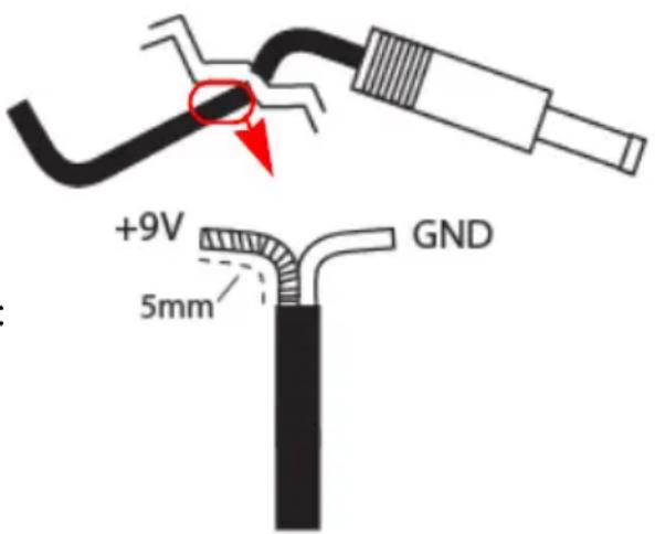

The exposed wires must constantly be separated from each other to prevent any unexpected damage (including short-circuits, electric shocks, and so on.)
- Insert the exposed +9V wire and GND wire tightly into the provided 2-pin Terminal Block Connector. The connector is properly labeled – the +9V and GND wires should be plugged into the correct holes.

(Continues on next page.)
Note: The device can be damaged if incorrectly paired wires are inserted into the terminal block. A voltmeter is one of the tools used to measure an exposed wire's polarity (i.e., +9V or GND).
-
Connect and snap the Terminal Block Connector into the 2-pin Terminal Block located on either the Transmitter or Receiver unit's rear panel.
-
Connect the other end of the power adapter to a power socket.
Note: If you wish to use another external power supply, ensure that it stays within a voltage range of +9V\~12V.

Wall Mounting
At this point, the site(s) for wall-mounting the VE157 / VE607 / VE807 should be ready. Note that there are cable connections to be made at the rear panel of the units – see Hardware Installation.
- Screw the VE157 / VE607 / VE807 to the wall plate.

- Screw the Wall Plate to the installation site (wall, ceiling, and so on).
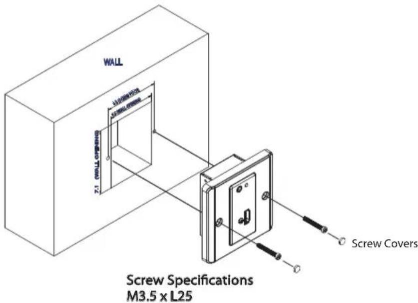
-
After making the necessary unit-to-unit Cat 5e cable connections, as well as the terminal block connection (optional), attach the Wall Plate Cover to secure and cover the VE157 / VE607 / VE807.
-
After mounting the VE157 / VE607 / VE807, you can proceed to Hardware Installation on page 11.
Hardware Installation
After mounting the VE157 / VE607 / VE807 Transmitter and Receiver units, you can conveniently connect the VE157 / VE607 / VE807 wall plate covers to your input/output equipment. Refer to the installation diagram on the following page (the numbers in the diagrams correspond to the steps below), and do the following:
- Connect the Video IN Port on the VE157T / VE607T / VE807T (Transmitter) to the Video OUT port on your video source device.
- Connect one end of the audio cable to the Audio IN port of the VE157T / VE607T / VE807T and connect the other end to the Audio OUT port of the source device.
- Connect the Video OUT port on the VE157R / VE607R / VE807R (Receiver) to the Video IN port on your video display device using the VGA/DVI/HDMI cable that came with your display device.
- Connect your speakers to the Audio OUT port on the VE157R / VE607R / VE807R.
- Connect the Transmitter or Receiver to a power outlet using the provided terminal block connector / power adapter – see How to Supply Power, page 8.
- Connect one end of the Cat 5e cable to the Line OUT port (VE157T) / TMDS port (VE607T / VE807T) on the Transmitter unit. Connect the other end of the Cat 5e cable to the Line IN port (VE157R) / TMDS port (VE607R / VE807R) on the Receiver unit.
- (Optional) Use a second Cat 5e cable to connect the Power ports (VE156T / VE156R) / DDC ports (VE607T / VE607R / VE807T / VE807R).
Note: 1. A second Cat 5e cable connection is required only if you need to transmit power to either Transmitter or Receiver.
-
For VE607 / VE807, in addition to the above, a second Cat 5e cable is only required if you need to use real EDID Bypass and HDCP key authentication.
-
Power on your source and display devices.

Overview
This chapter describes the Manual Gain Control / EQ switch located on the front panel of the Remote Unit that adjusts the VGA / DVI / HDMI display to obtain the best video quality.
Picture Adjustment
The quality of the video signal can decrease with distance. To adjust the video quality, do the following:
- VE157 – Use the Manual Gain Control switch by turning the knob clockwise to increase the video signal, or turning the knob counterclockwise to decrease the video signal – until you obtain the desired picture quality.
- VE607 / VE807 – Use the EQ switch to adjust the equalization strength and improve a blinking image.
The Equalization values range from 0-7 where:
◆ 7: strongest equalization
◆ 0: weakest equalization
This Page Intentionally Left Blank
Safety Instructions
General
- Read all of these instructions. Save them for future reference.
◆ Follow all warnings and instructions marked on the device. - This product is for indoor use only.
- Do not place the device on any unstable surface (cart, stand, table, etc.). If the device falls, serious damage will result.
♦ Do not use the device near water. - Do not place the device near, or over, radiators or heat registers.
- The device cabinet is provided with slots and openings to allow for adequate ventilation. To ensure reliable operation, and to protect against overheating, these openings must never be blocked or covered.
- The device should never be placed on a soft surface (bed, sofa, rug, etc.) as this will block its ventilation openings. Likewise, the device should not be placed in a built-in enclosure unless adequate ventilation has been provided.
- Never spill liquid of any kind on the device.
- Unplug the device from the wall outlet before cleaning. Do not use liquid or aerosol cleaners. Use a damp cloth for cleaning.
- The device should be operated from the type of power source indicated on the marking label. If you are not sure of the type of power available, consult your dealer or local power company.
- To prevent damage to your installation it is important that all devices are properly grounded.
- Do not allow anything to rest on the power cord or cables. Route the power cord and cables so that they cannot be stepped on or tripped over.
- Position system cables and power cables carefully; Be sure that nothing rests on any cables.
- Never push objects of any kind into or through cabinet slots. They may touch dangerous voltage points or short out parts resulting in a risk of fire or electrical shock.
- Do not attempt to service the device yourself. Refer all servicing to qualified service personnel.
- If the following conditions occur, unplug the device from the wall outlet and bring it to qualified service personnel for repair.
- The power cord or plug has become damaged or frayed.
- Liquid has been spilled into the device.
- The device has been exposed to rain or water.
- The device has been dropped, or the cabinet has been damaged.
- The device exhibits a distinct change in performance, indicating a need for service.
- The device does not operate normally when the operating instructions are followed.
- Avoid circuit overloads. Before connecting equipment to a circuit, know the power supply’s limit and never exceed it. Always review the electrical specifications of a circuit to ensure that you are not creating a dangerous condition or that one does not already exist. Circuit overloads can cause a fire and destroy equipment.
- Only adjust those controls that are covered in the operating instructions. Improper adjustment of other controls may result in damage that will require extensive work by a qualified technician to repair.
Technical Support
International
- For online technical support – including troubleshooting, documentation, and software updates: http://eservice.aten.com
◆ For telephone support, see Telephone Support, page iii:
North America
| Email Support support@aten-usa.com | ||
| Online Technical Support | Troubleshooting Documentation Software Updates | http://eservice.aten.com |
| Telephone Support 1-888-999-ATEN | ext 4988 | |
When you contact us, please have the following information ready beforehand:
◆ Product model number, serial number, and date of purchase.
- Your computer configuration, including operating system, revision level, expansion cards, and software.
◆ Any error messages displayed at the time the error occurred.
◆ The sequence of operations that led up to the error.
◆ Any other information you feel may be of help.
Supported ATEN Products
The VE157 / VE607 / VE807 Transmitter and Receiver can each be used separately with other VGA/DVI/HDMI extenders, as follows:
| VE157 VE022 VE170 VS1204T VS1208T | ||
| VE607 VE600A | ||
| VE807 VE800A VS1804T VS1808T | ||
| VE807R VB802 | ||
Specifications
| Function VE157T VE157R | |||
| Connectors Video In 1 x HDB-15 Female (Blue) | N/A | ||
| Video Out N/A 1 x HDB-15 Female (Blue) | |||
| Audio In 1 x 3.5mm Stereo Jack (Green) | N/A | ||
| Audio Out N/A 1 x 3.5mm Stereo Jack (Green) | |||
| Power 1 x RJ-45 Female (Silver) | |||
| Power 1 x Terminal Block (Green) | |||
| Line In N/A 1 x RJ-45 Female (Silver) | |||
| Line Out 1 x RJ-45 Female (Silver) | N/A | ||
| LED Power | 1 (Green) | ||
| Link | N/A | 1 (Amber) | |
| Switch | Manual Gain Control | N/A | 1 x Knob |
| Video | 1920 x 1200 @ 60 Hz (30 m)1280 x 1024 @ 60 Hz (150 m) | ||
| Power Consumption | DC 9V, 3.2W | ||
| Environment | Operating Temp. | 0–50°C | |
| Storage Temp. | -20–60°C | ||
| Humidity | 0–80% RH, Non-condensing | ||
| Physical Properties | Housing | Metal | |
| Weight | 0.17 kg | ||
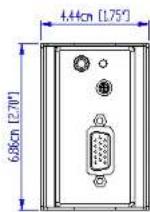
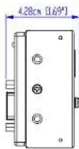
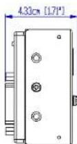
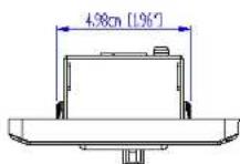
| Dimensions (L x W x H) | 10.41 x 4.40 x 4.40 cm | ||
| Function VE607T VE607R | |||
| Connectors Video In 1 x DVI-D Female | (White) | N/A | |
| Function VE807T VE807R | ||
| Connectors Video In | 1 x HDMI Type A Female (Black) | N/A |
| Video Out N/A | 1 x HDMI Type A | Female (Black) |
| Audio In 1 x 3.5mm Stereo | Jack (Green) | N/A |
| Audio Out N/A 1 x 3.5mm Stereo | Jack (Green) | |
| DDC 1 x RJ-45 Female (Silver) | ||
| Power 1 x Terminal Block (Green) | ||
| TMDS 1 x RJ-45 Female (Silver) | ||
| LED Power / Link 1 (Green / Amber) | ||
| Function VE807T | VE807R | ||
| Switch EQ Switch N/A 1 x Knob | |||
| Video 1080p @ 60 Hz (40m) | 1080i @ 60 Hz (60m) | ||
| Power Consumption DC 9V, 2.9W | |||
| Environment | Operating Temp. 0–50°C | ||
| Storage Temp. -20–60°C | |||
| Humidity 0–80% RH, Non-condensing | |||
| Physical Properties | Housing Metal | ||
| Weight 0.17 kg | |||
| Dimensions (L x W x H) | 10.41 x 4.40 x 4.00 cm | ||
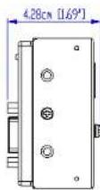
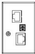
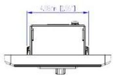
CAD Drawings

![1.6cm [0.63"] 0.95cm [0.37"]](/content/2026/06/1187558/images/cbabc33ab61e558ddccc45499b6125d3bda85b14aa847ac3678b1d1de8be5406.jpg)
ATEN
VE157T


ATEN
VE157T
![Outer [200V] Inner [200V]](/content/2026/06/1187558/images/cfefa7a72f78edf3dcd2badd41f9b5132c51a9cb7a27e0bad8fe4f325025ecd1.jpg)
![420 x [1.69] 250 x [2.35] 620 x [7.71]](/content/2026/06/1187558/images/306150364865c37a318f3f2ff2754db1931d1f683f9f5556a9e1f1161c9e6726.jpg)
![5r [28]](/content/2026/06/1187558/images/f60c58ba99737c38bdc47583808d4e5fc88701ac35754918e2dfcf76e40581c4.jpg)
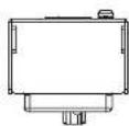
CAD Drawings

![1.6cm [0.63"] 0.95cm [0.37"]](/content/2026/06/1187558/images/b996e7efce6f4cb69e84822eaac65bbf70c2e0681e28c1d95e5348cdb9e59fcf.jpg)
ATEN
VE157R

ATEN
VE157R

![Rer [L2V] Rer [L3V]](/content/2026/06/1187558/images/253b7091d145a1ee5a1f430ac60f14a7b90d9728a9099e7733d67e9b76e56f4c.jpg)
![420 x [1.67] 250 x [1.35] 600 x [1.17]](/content/2026/06/1187558/images/55f15f15f4890621cf9c4a92d3b65b3f64f07243da79905c8548a43485ee829e.jpg)
![5r [2.8]](/content/2026/06/1187558/images/31f02ed10469373e0438f6f1b4ddb80c1e795fdb0c3c3aaa209fbd29fe7f39f2.jpg)
CAD Drawings

![1.6cm [0.63"] 0.95cm [0.37"]](/content/2026/06/1187558/images/6f5aa2a438d9521790816c4031217f94b9705dae302355df592f974076d30492.jpg)
ATEN
VE607T



ATEN
VE607T
![86cm [339°] 86cm [339°]](/content/2026/06/1187558/images/e5e217fd4492f2f04eb7c5b4b8dd2de7dce1e25be174cff37e1011652556b7af.jpg)
![4.33cm [1.7"x] 2.69cm [1.06"x] 6.86cm [2.7"x]](/content/2026/06/1187558/images/96608c9da491a8b2f0b3cca3bd6576d0cba4f0c170b551e4d73db6d7e0a02604.jpg)
![6cn [236°]](/content/2026/06/1187558/images/4e0bb2fec9e7ccb7b53a5b6528a5618835b3c46618e4e457845e8286f368998e.jpg)
ATEN
VE607T
CAD Drawings

![1.6cm [0.63"] 0.95cm [0.37"]](/content/2026/06/1187558/images/7f53aaac9d7a12cd7426f8a3befa144729036d0092c963100bf9432f1845bc95.jpg)
ATEN
VE607R

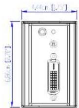

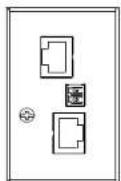
ATEN
VE607R
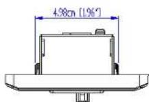
![86cm [339°] 86cm [339°]](/content/2026/06/1187558/images/5f10e2b94e1d5ab642829464a58e37e8197443739822f79084c7fc21791742f8.jpg)

![6cn [236°]](/content/2026/06/1187558/images/0801d3e1bd630a1eef0096d271bb1938a156c15b08c804b0d64177c5594c26ab.jpg)
ATEN
VE607R
CAD Drawings

![1.6cm [0.63°] 0.95cm [0.37°]](/content/2026/06/1187558/images/1a46cd917ef714d129e0482d0da1306de5e213a959b8d41fca269ef539dcb2b0.jpg)
ATEN
VE807T
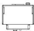


ATEN
VE807T
![86cm [339°] 86cm [339°]](/content/2026/06/1187558/images/8a81838b1b03509fc3dfd20cf98a9b4aea4f0c17e6056d28328665250e064971.jpg)
![4cm [1.57°] 2.69cm [1.06°] 6.8cm [2.70°]](/content/2026/06/1187558/images/ac420126d732d2ed6ba3a1ce701c44ffd184cb8b84955d6b9923f8410cdbc296.jpg)
![6cn [236°]](/content/2026/06/1187558/images/97c5c3e9d784d80b7627af754e724ac59e45ebcfedc152ae0a2342e396bdb561.jpg)
ATEN
VE807T
CAD Drawings

![1.6cm [0.63°] 0.95cm [0.37°]](/content/2026/06/1187558/images/a67ac86440dae612541a05db94f4843fbca6869a3e975c8ede802142678fa61f.jpg)
ATEN
VE807R


ATEN
VE807R

![86cm [339°] 86cm [339°]](/content/2026/06/1187558/images/87a2938fb3f0cc8b1686bb942078b4180f84f84dbc1f578c4857ee0faf79d1f8.jpg)
![4cm (1.57") 2.69cm (1.06") 6.8cm [2.70]](/content/2026/06/1187558/images/37c9bc1f60dec5ec6c8ca13b5aa0cf520c614fffe5e86df13725fa7b5e944d6d.jpg)
![6cm [2.36']](/content/2026/06/1187558/images/0d655ae8d01fa17d379dbf5794ff6d58e7b40623bd83e3bfa0c6ca5595eb76b0.jpg)
ATEN
VE807R
Panel Mount Cutout
![Width of faceplate = 8.6 cm [3.39"] Height of faceplate = 8.6 cm [3.39"] 5.2 cm [2.05"] 7.1 cm [2.80"] Cutout Area](/content/2026/06/1187558/images/377cf953958cf24a845ef03babd8075de92804a56a02e980cf3422d1bcc142d1.jpg)
Note: ATEN recommends a 1-gang wall box with a depth of at least 4.5 cm (1.77 inches) to accommodate the connectors and cables.
ATEN
VE157/607/807
Limited Warranty
ATEN warrants its hardware in the country of purchase against flaws in materials and workmanship for a Warranty Period of two [2] years (warranty period may vary in certain regions/countries) commencing on the date of original purchase. This warranty period includes the LCD panel of ATEN LCD KVM switches. Select products are warranted for an additional year (see A+ Warranty for further details). Cables and accessories are not covered by the Standard Warranty.
What is covered by the Limited Hardware Warranty
ATEN will provide a repair service, without charge, during the Warranty Period. If a product is detective, ATEN will, at its discretion, have the option to (1) repair said product with new or repaired components, or (2) replace the entire product with an identical product or with a similar product which fulfills the same function as the defective product. Replaced products assume the warranty of the original product for the remaining period or a period of 90 days, whichever is longer. When the products or components are replaced, the replacing articles shall become customer property and the replaced articles shall become the property of ATEN.
To learn more about our warranty policies, please visit our website: http://www.aten.com/global/en/legal/policies/warranty-policy/


- EMC Information
- User Information
- Online Registration
- Telephone Support
- User Notice
- Package Contents
- Contents
- Introduction
- Hardware Setup
- Basic Operation
- Appendix
- About this Manual
- Conventions
- Product Information
- Overview
- Features
- Requirements
- Console
- Computer
- Cables
- Components
- Front View (Transmitter)
- Front View (Receiver)
- Rear View (Transmitter / Receiver)
- Chapter 2
- Hardware Setup
- Before Mounting
- Wall Plate Dimensions
- How to Supply Power
- Wall Mounting
- Hardware Installation
- Picture Adjustment
- Safety Instructions
- General
- Technical Support
- International
- Supported ATEN Products
- CAD Drawings
- Panel Mount Cutout
- Limited Warranty
- What is covered by the Limited Hardware Warranty
Brand : ATEN
Model : VE157
Category : AV Switch