EXT-CAT5-4000 - Émetteur AV Gefen - Free user manual and instructions
Find the device manual for free EXT-CAT5-4000 Gefen in PDF.

User questions about EXT-CAT5-4000 Gefen
0 question about this device. Answer the ones you know or ask your own.
Ask a new question about this device
Download the instructions for your Émetteur AV in PDF format for free! Find your manual EXT-CAT5-4000 - Gefen and take your electronic device back in hand. On this page are published all the documents necessary for the use of your device. EXT-CAT5-4000 by Gefen.
USER MANUAL EXT-CAT5-4000 Gefen
Technical Support Hours:
8:00 AM to 5:00 PM Monday thru Friday.
Write To:
Gefen Inc.
c/o Customer Service
20600 Nordhoff St
Chatsworth, CA 91311
www.gefen.com
support@gefen.com
Notice
Gefen Inc. reserves the right to make changes in the hard ware, packaging and any accompanying doc u men ta tion without prior written notice.
CAT5·4000 Extender is a trademark of Gefen Inc.
1 Introduction
2 Operation Notes
3 Features
4 Sender Panel Layout
5 Sender Panel Descriptions
6 Sender Panel Descriptions
7 Notes (Intensionally Left Blank)
8 Receiver Panel Layout
9 Receiver Panel Descriptions
10 Connecting The CAT5·4000 Extender Analog (VGA)
11 Connecting/Adjusting The CAT5·4000 Analog (VGA)
12 Connecting The CAT5·4000 Extender Digital (DVI)
13 Connecting/Adjusting The CAT5·4000 Digital (DVI)
14 RS-232 Serial Communication Configuration
15 Specifications
16 Warranty
Congratulations on your purchase of the CAT5•4000 Extender. Your complete satisfaction is very important to us.
Gefen
Gefen delivers innovative, progressive computer and electronics add-on solutions that harness integration, extension, distribution and conversion technologies. Gefen's reliable, plug-and-play products supplement cross-platform computer systems, professional audio/video environments and HDTV systems of all sizes with hard-working solutions that are easy to implement and simple to operate.
The Gefen CAT5·4000 Extender
The Gefen CAT5•4000 Extender is an exceptional solution for extending up to three individual analog or digital sources to up to four remote locations. The first input is mirrored to two outputs. RS-232 serial communication (four individual inputs) and stereo analog audio (available for the mirrored outputs) are also provided for extension.
How It Works
The CAT5•4000 Extender employs DVI-I inputs which will support both an analog and digital signals. This will allow the user to connect VGA and DVI sources. Connect the source devices to the CAT5•4000 sender unit using DVI-A cables (analog) and DVI-D cables (digital). Connect up to four RS-232 sources and a single audio analog stereo to the CAT5•4000 sender unit. Then, using inexpensive and widely available CAT-5, CAT-5e or CAT-6 cables, connect up to four CAT5•4000 receiver units to the CAT5•4000 sender unit at the remote locations. Connect a display to the CAT5•4000 receiver at each location. If using the RS-232 or analog stereo extension, connect the corresponding equipment to each CAT5•4000 receiver. Once all devices are connected and are receiving power a perfectly reproduced video signal should appear on the displays at the remote locations.
READ THESE NOTES BEFORE INSTALLING OR OPERATING THE CAT5·4000 EXTENDER
• Maximum distance ratings:
• VGA 1920x1200 60Hz is 330 feet.
• DVI 1920x1200 60Hz is 130 feet.
• DVI 1280x1024 60Hz is 300 feet.
• VGA Supported resolutions: 640 x 480 through 1920 x 1200
• DVI Supported resolutions: 640 x 480 through 1920 x 1080
- The CAT5•4000 Extender can send only one video type, either analog or digital, from each input. While the DVI-I input can accept both types, please ensure that only one type of signal is being used by using either a DVI-A or DVI-D cable.
- The channel 1 video input will be mirrored to two separate outputs on the CAT5•4000 sender unit. However, two separate RS-232 inputs are provided and will accommodate an individual RS-232 device for each of the two mirrored video outputs.
- Analog stereo audio connected via the 3.5mm mini-stereo input jack will be transmitted through the mirrored outputs on channel 1 only.
- Channels two and three do not support audio extension.
- Channels two and three have individual RS-232 connections for use.
- When analog video is used on channels two and three, only a single CAT-5, CAT-5e or CAT-6 will be required for full video and RS-232 extension. When digital video is being used, two CAT-5, CAT-5e or CAT-6 cables will be required for full video and RS-232 support.
- When analog or digital video is used on channel one (this applies to either of the mirrored outputs), two CAT-5, CAT-5e or CAT-6 cables will be required for full video, audio, and RS-232 support.
- The CAT5•4000 receiver units need to be configured for use on either channel 1 (dual outputs) or for use on channels 2 and 3. There is a DIP (Dual In-line Package) switch bank located on the underside of the CAT5•4000 receiver that will set the unit for proper operation for either channel 1 (both outputs) or for channels 2 or 3. Please see page 14 for details on how to change these DIP switches.
Features
- Both analog and digital video signals are supported through the use of DVI-I inputs.
• DVI video is transmitted digitally for zero signal loss
• Supports resolutions up to 1080p, 2K, and 1920 x 1200
• Supports DDWG standard for DVI compliant monitors - Analog audio extension (For channel 1 only)
• RS-232 serial communications extension for all channels - Uses industry-standard CAT5/CAT6 cable
- Extends VGA up to 330 feet (100m) with RS-232
- Extends DVI up to 130 feet (40m) with RS-232
• DVI Video EQ enhancement controls (brightness, sharpness)
Package Includes
(1) CAT5·4000 Extender Sender Unit
(3) 6 Foot DVI-D Cable (M-M)
(3) 6 Foot VGA to DVI-A Cable (M-M)
(4) 6 Foot DB-9 RS-232 Cable (M-F)
(1) 6 Foot 3.5mm Stereo Mini-Jack Audio Cable (M-M)
(2) 5V DC Power Supply
(1) User's Manual
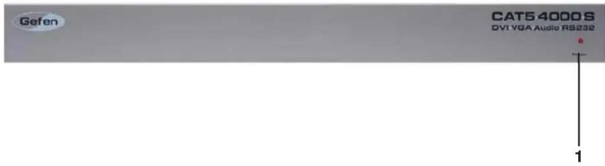
Front Panel
text_image
Gefen CAT54000S DVI VGA Audio RS232 1Back Panel

text_image
2 HCA-0123 A#N1# VCA-0123 A#N1# CYMB23# M#N1# CYMB23# M#N1# C#N1# 5 6 8 11 10 3 4 7 9 C#N1# C#N2# C#N3# C#N4# C#N5# C#N6# C#N7# C#N8# C#N9# C#N10# C#N11# C#N12# C#N13# C#N14# C#N15# C#N16# C#N17# C#N18# C#N19# C#N20# C#N21# C#N22# C#N23# C#N24# C#N25# C#N26# C#N27# C#N28# C#N29# C#N30# C#N31# C#N32# C#N33# C#N34# C#N35# C#N36# C#N37# C#N38# C#N39# C#N40# C#N41# C#N42# C#N43# C#N44# C#N45# C#N46# C#N47# C#N48# C#N49# C#N50# C#N51# C#N52# C#N53# C#N54# C#N55# C#N56# C#N57# C#N58# C#N59# C#N60# C#N61# C#N62# C#N63# C#N64# C#N65# C#N66# C#N67# C#N68# C#N69# C#N70# C#N71# C#N72# C#N73# C#N74# C#N75# C#N76# C#N77# C#N78# C#N79# C#N80# C#N81# C#N82# C#N83# C#N84# C#N85# C#N86# C#N87# C#N88# C#N89# C#N90# C#N91# C#N92# C#N93# C#N94# C#N95# C#N96# C#N97# C#N98# C#N99# ECE##1 Power LED Indicator
This LED will become active once the included 5V DC power supply is properly connected between the unit and an open wall power socket.
2 RS-232 Serial Communication Input 1-4
These inputs will support RS-232 serial communications devices. Only pins 2 (RX), 3 (TX), and ground (5) are supported. Four inputs are provided. The CAT5•4000 receiver units must be configured for RS-232 operation for either channel 1 (both outputs) or for channels 2 and 3. Please see page 14.
3 Channel 1 VGA and Audio RJ-45 Port 1-2
When the input video source is analog, these RJ-45 ports connect the CAT5•4000 sender to a CAT5•4000 receiver unit using CAT-5, CAT-5e or CAT-6 cabling. Analog video and audio are transmitted through this connector. Two ports are provided for mirrored video output of the channel 1 source to two separate locations. If RS-232 extension is required, a second CAT-5 cable must be connected using the channel 1 DVI/RS-232 RJ-45 port. Once a link between the sender and receiver unit has been established, the green LED indicator located on these ports will become active.
4 Channel 1 DVI and RS-232 RJ-45 Port 1-2
When the input video source is digital, these RJ-45 ports connect the CAT5•4000 sender to a CAT5•4000 receiver unit using CAT-5, CAT-5e or CAT-6 cabling. Digital video and RS-232 are transmitted through this connector. Two ports are provided for mirrored video output of the channel 1 source to two separate locations. If audio extension is required, a second CAT-5 cable must be connected using the channel 1 VGA/RS-232 RJ-45 port. Once a link between the sender and receiver unit has been established, the green LED indicator located on these ports will become active.
5 Channel 1 DVI Input
Connect an analog or digital source to this DVI-I input port. Depending on the input video signal type, analog or digital, a mirrored signal will be output to either the dual VGA or DVI RJ-45 ports.
6 3.5mm Analog Stereo Audio Mini-Jack Input
Connect an analog stereo audio source to this input port. The audio source connected to this input will be mirrored and output through both of the VGA/Audio RJ-45 ports. This audio source will not be output through any of the channel 2 and 3 RJ-45 output ports.
7 Channel 2 VGA/RS-232 and DVI/DDC RJ-45 Ports
These RJ-45 ports connect the CAT5•4000 sender to a CAT5•4000 receiver unit using CAT-5, CAT-5e or CAT-6 cabling. When the input source is analog, the VGA/RS-232 port is used. When the input source is digital, the DVI/DDC port is used. If RS-232 is required when using a digital input source, use both RJ-45 ports.
8 Channel 2 DVI Input
Connect an analog or digital source to this DVI-I input port.
9 Channel 3 VGA/RS-232 and DVI/DDC RJ-45 Ports
These RJ-45 ports connect the CAT5•4000 sender to a CAT5•4000 receiver unit using CAT-5, CAT-5e or CAT-6 cabling. When the input source is analog, the VGA/RS-232 port is used. When the input source is digital, the DVI/DDC port is used. If RS-232 is required when using a digital input source, use both RJ-45 ports.
10 Channel 3 DVI Input
Connect an analog or digital source to this DVI-I input port.
11 5V DC Power Receptacle
Connect the included 5V DC power supply between this input and an open wall power socket.
Front Panel

text_image
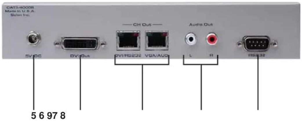
Gefen CAT5 4000 R DVI VGA Audio RS232 1 2 3 4Back Panel
text_image
CAT3-4000R Made in U.S.A. Galen Inc. 5V/DC DV1/Out CH Out DVI/RG222 VGA/AUD Audio Out L P DSA32 5 6 97 81 Brightness Trim Pot
When using an analog input video source, use this Trim Pot to brighten/darken the output video. Please see page 11 for detailed instructions on the usage.
2 Focus Trim Pot
When using an analog input video source, use this Trim Pot to blur/sharpen the output video. Please see page 11 for detailed instructions on the usage.
3 Equalization Dial
When using a digital input video source, use this equalization dial to tune the incoming video signal. Please see page 13 for detailed instructions on the usage.
4 Power LED Indicator
This LED will become active once the included 5V DC power supply is properly connected between the unit and an open wall power socket.
5 5V DC Power Receptacle
Connect the included 5V DC power supply between this input and an open wall power socket.
6 DVI-I Output
This DVI-I output port will support an analog or digital output display device. A DVI to VGA adapter will be required when using a VGA capable display with this output port.
7 DVI/RS-232 and VGA/Audio RJ-45 Ports
These RJ-45 ports connect the CAT5•4000 receiver to the CAT5•4000 sender unit using CAT-5, CAT-5e or CAT-6 cabling. When using an analog or digital video source on the channel 1 input, connect the CAT-5 cables according to the labels on both the sender and receiver units. When using an analog video source with the channel 2 or 3 inputs, connect a CAT-5 cable from the VGA/RS-232 RJ-45 port on the sender unit to the VGA/Audio RJ-45 port on the receiver unit. When using a digital video source with the channel 2 or 3 inputs, connect a CAT-5 cable from the DVI/DDC RJ-45 port on the sender unit to the DVI/RS-232 RJ-45 port on the receiver unit. Additionally, if RS-232 extension is required when using a digital video source on channel 2 or 3, a second CAT-5 cable must be used to connect the VGA/RS-232 RJ-45 port on the sender unit to the VGA/Audio RJ-45 port on the receiver unit.
8 Analog Stereo Audio RCA Outputs
When using the CAT5•4000 receiver unit with channel 1, audio will be transmitted to these RCA outputs. Connect an amplified audio output device to these RCA output connectors.
9 RS-232 Serial Communication Output
This output will support a RS-232 serial communications device. Only pins 2 (RX), 3 (TX), and ground (5) are supported. This output will only be available when the proper RJ-45 connections for RS-232 functionality are present. The CAT5•4000 receiver units must be configured for RS-232 operation for either channel 1 (both outputs) or for channels 2 and 3. Please see page 14.
How to Connect the CAT5·4000 Extender Using an Analog (VGA) Source
- Connect up to three analog (VGA) sources to the DVI-I inputs on the CAT5•4000 sender unit. VGA to DVI-A cables/adapters will be necessary to make these connections. 3 VGA to DVI-A cables are supplied.
- Connect an analog stereo audio source to the 3.5mm stereo audio mini-jack port on the CAT5•4000 sender unit.
- Connect up to four RS-232 source devices to the RS-232 input ports on the CAT5•4000 sender unit.
NOTE: Only pins 2 (RX), 3 (TX), and ground (5) are supported for RS-232 serial communication. Although there are two mirrored video outputs for channel 1, there are 2 separate RS-232 connectors available for individual extension. RS-232 1 corresponds to the Mon 1 output and RS-232 2 corresponds to the Mon 2 output. To enable the RS-232 on channel 1's dual RS-232 ports, the CAT5•4000 receiver must be configured properly. Please see page 14 for instructions on how to do this.
- Using CAT-5, CAT-5e or CAT-6 cables, connect the CAT5•4000 receiver units to the sender unit. Up to 4 receiver units can be used. Please use the specific instructions below for connecting channels 1 through 3.
• Channel (21mirrored outputs are available. These are labeled Mon 1 and Mon 2)
- Connect the port labeled VGA/Audio on the sender unit to the port labeled VGA/Audio on the receiver unit.
- Connect the port labeled DVI/RS-232 on the sender unit to the port labeled DVI/RS-232 on the receiver unit. (This cable connection will not be necessary if RS-232 extension is not needed)
NOTE: These outputs will mirror the single input on channel 1. When making connections from the sender to receiver, please ensure that both CAT-5 cables for the outputs labeled Mon 1 are sent to the same location and both CAT-5 cables for Mon 2 are sent to the same location.
- Channels 2 and 3
- Connect the port labeled VGA/RS-232 on the sender unit to the port labeled VGA/Audio on the receiver unit.
-
When using analog (VGA) sources, the RJ-45 port labeled DVI/DDC will not need to be connected.
-
Connect an analog (VGA) capable display to the DVI-I output on the CAT5•4000 receiver unit. A DVI to VGA cable/adapter will be necessary to make this connection.
How to Connect the CAT5·4000 Extender Using an Analog (VGA) Source (Continued from the previous page)
- For receivers connected to channel 1, connect a amplified stereo output device to the RCA analog stereo audio outputs on the receiver unit. Channels 2 and 3 do not support audio extension.
- Connect a RS-232 device to the RS-232 connector on the CAT5•4000 receiver unit.
- Connect the included 5V DC power supplies both the CAT5•4000 sender and receiver units.
- Power on all displays first and the source devices second. Once all connections have been properly made and power has been applied, the green LED indicators above the VGA RJ-45 ports should be lit on the sender unit and all receiver units.
NOTE: There are status indicators above each RJ-45 port. Green indicators will be active on "Sync Detect". Red indicators will be active when the "Analog Power" is detected.
Adjusting the CAT5·4000 Extender Using an Analog (VGA) Source
The CAT5•4000 was designed for plug-and-play installation. However, differences in CAT-5 cabling quality and skew rates may require the user to adjust the brightness and focus of the resulting video output. If the output video is too blurry/sharp or dark/bright please use the instructions below to adjust the output quality.
- Locate the Brightness (Br) and Focus (Fo) Trim Pots on the front panel of the CAT5·4000 receiver.
- Insert a small flat-head tool into the desired Trim Pot receptacle.
- Turn the Trim Pot in either a clockwise or counter-clockwise motion until the desired adjustment level is reached. The Trim Pot has a limited range in both directions. Please do not force the Trim Pot beyond the point at which it stops turning as this may break the Trim Pot.
- Remove the adjustment tool from the Trim Pot receptacle.
How to Connect the CAT5·4000 Extender Using an Digital (DVI) Source
- Connect up to three digital (DVI) sources to the DVI-I inputs on the CAT5•4000 sender unit. DVI-D cables should be used to ensure that digital video is being transmitted.
- Connect an analog stereo audio source to the 3.5mm stereo audio mini-jack port on the CAT5•4000 sender unit.
- Connect up to four RS-232 source devices to the RS-232 input ports on the CAT5•4000 sender unit.
NOTE: Only pins 2 (RX), 3 (TX), and ground (5) are supported for RS-232 serial communication. Although there are two mirrored video outputs for channel 1, there are 2 separate RS-232 connectors available for individual extension. RS-232 1 corresponds to the Mon 1 output and RS-232 2 corresponds to the Mon 2 output. To enable the RS-232 on channel 1's dual RS-232 ports, the CAT5•4000 receiver must be configured properly. Please see page 14 for instructions on how to do this.
- Using CAT-5, CAT-5e or CAT-6 cables, connect the CAT5•4000 receiver units to the sender unit. Up to 4 receiver units can be used. Please use the specific instructions below for connecting channels 1 through 3.
• Channel (21mirrored outputs are available. These are labeled Mon 1 and Mon 2)
- Connect the port labeled DVI/RS-232 on the sender unit to the port labeled DVI\RS-232 on the receiver unit.
- Connect the port labeled VGA/Audio on the sender unit to the port labeled VGA/Audio on the receiver unit. (This cable connection will not be necessary if audio extension is not needed)
NOTE: These outputs will mirror the single input on channel 1. When making connections from the sender to receiver, please ensure that both CAT-5 cables for the outputs labeled Mon 1 are sent to the same location and both CAT-5 cables for Mon 2 are sent to the same location.
- Channels 2 and 3
- Connect the port labeled DVI/DDC on the sender unit to the port labeled DVI/RS-232 on the receiver unit.
-
When using digital (DVI) sources, the RJ-45 port labeled VGA/RS-232 will need to be connected to the port labeled VGA/Audio on the receiver unit. This cable is not necessary if RS-232 extension is not required.
-
Connect an digital (DVI) capable display to the DVI-I output on the CAT5•4000 receiver unit. DVI-D cables should be used to ensure that digital video is being transmitted.
How to Connect the CAT5·4000 Extender Using an Analog (VGA) Source (Continued from the previous page)
- For receivers connected to channel 1, connect a amplified stereo output device to the RCA analog stereo audio outputs on the receiver unit.
Channels 2 and 3 do not support audio extension. Connect a RS-232 device to the RS-232 connector on the CAT5•4000 receiver unit. - Connect the included 5V DC power supplies both the CAT5•4000 sender and receiver units.
- Power on all displays first and the source devices second. Once all connections have been properly made and power has been applied, the green LED indicators above the DVI RJ-45 ports should be lit on the sender unit and all receiver units.
NOTE: There are status indicators above each RJ-45 port. Green indicators will be active when the “DVI Clock” is present. Red indicators will be active when the receiver detects a display or “Hot Plug Detect”. The receiver’s Red indicator will indicate the current position for DIP switch 1 on the receiver (please see page 14 for more information).
Adjusting the CAT5·4000 Extender Using an Digital (DVI) Source
The CAT5•4000 was designed for plug-and-play installation. However, differences in CAT-5 cabling quality and skew rates may require the user to adjust the equalization setting to obtain a video output. If there is no video output, or if the video output is not stable, please follow the instructions below to adjust the equalization.
- Locate the Equalization adjustment dial on the front panel of the CAT5•4000 receiver.
- Insert a small fl at-head tool into the Equalization dial.
- Turn the dial in either a clockwise or counter-clockwise direction until the desired adjustment level is reached. The Equalization has 16 positions (0-9 and then A-F) that can be set. The dial will "click" into each position. Please ensure that the dial is set to one of the positions and is not in-between two positions.
- Remove the adjustment tool from the Equalization dial.
RS-232 Serial Control
The RS-232 transmission from the CAT5•4000 receiver units must be configured for use on either channel 1 or on channels 2 and 3. By default, the CAT5•4000 units are configured to work on channels 2 and 3. To enable the RS-232 transmission for channel 1, a DIP (Dual In-line Package) switch must be enabled. This DIP switch is located on the underside of the CAT5•4000 receiver unit beneath a piece of metallic colored tape.
When using the CAT5•4000 receiver unit for the dual outputs on channel 1, please use the instructions below to enable the proper RS-232 transmission between the sender and receiver units.
Enable RS-232, DDC and HPD for channels 2 and 3: Default

natural_image
Two white squares on a black background, no text or symbols present.1 2
Enable RS-232 for both ports on channel 1:

natural_image
Two white squares on a black background, no text or symbols present1 2
- Locate the DIP switches on the underside of the CAT5•4000 sender unit. The DIP switches will be covered by a small piece of metallic tape.
- Using a small pointed tool, such as a pin, flip the switch to the desired position.
Analog Video Amplifier Bandwidth 350 MHz
Digital Video Amplifier Bandwidth 165 MHz
VGA Video Input / Output Connectors ...... DVI-I 29-pin female
VGA Video Frequency Ranges 15-70 KHz Horizontal, 30-75 Hz Vertical
VGA DDC signal 0.75V p-p TTL
DVI Video Input / Output Connectors .... DVI-I 29-pin female
DVI DDC signal 5V p-p TTL
Audio In 3.5mm female mini-phone jack, stereo
Audio Out 2 x RCA (L/R red/white)
Audio Frequency response 20 Hz to 20 kHz, +/-1 dB
THD 0.1%
Link Connector RJ-45
Serial Communication Protocol ......RS-232C
RS-232 .... Supports RX, TX, RTS protocols
Max. baud rate 115200kbps
Power Consumption (Each Unit) 20 Watts (max.)
Power Supply (Each Unit) 5V DC (Ex ter nal)
Dimensions Sender 17" W x 1.75" H x 5.5" D
Dimensions Receiver 8.375" W x 1.75" H x 4.25" D
Rack Mountable .... 1 Rack Spaces
Shipping Weight 8 Lbs