EXT-DVI-FO-141 - Émetteur AV Gefen - Free user manual and instructions
Find the device manual for free EXT-DVI-FO-141 Gefen in PDF.

User questions about EXT-DVI-FO-141 Gefen
0 question about this device. Answer the ones you know or ask your own.
Ask a new question about this device
Download the instructions for your Émetteur AV in PDF format for free! Find your manual EXT-DVI-FO-141 - Gefen and take your electronic device back in hand. On this page are published all the documents necessary for the use of your device. EXT-DVI-FO-141 by Gefen.
USER MANUAL EXT-DVI-FO-141 Gefen
Technical Support Hours:
8:00 AM to 5:00 PM Monday thru Friday.
Write To:
Gefen Inc.
c/o Customer Service
20600 Nordhoff St
Chatsworth, CA 91311
www.gefen.com
support@gefen.com
Notice
Gefen Inc. reserves the right to make changes in the hard ware, packaging and any accompanying doc u men ta tion without prior written notice.
DVI RS-232 over Fiber is a trademark of Gefen Inc.
1 Introduction
2 Operation Notes
3 Features
4 Sender Panel Layout
5 Sender Panel Descriptions
6 Receiver Panel Layout
7 Receiver Panel Descriptions
8 Connecting And Operating The DVI RS-232 Over Fiber
9 Network Cable Wiring Diagram
10 Specifications
11 Warranty
Congratulations on your purchase of the DVI RS-232 over Fiber. Your complete satisfaction is very important to us.
Gefen
Gefen delivers innovative, progressive computer and electronics add-on solutions that harness integration, extension, distribution and conversion technologies. Gefen's reliable, plug-and-play products supplement cross-platform computer systems, professional audio/video environments and HDTV systems of all sizes with hard-working solutions that are easy to implement and simple to operate.
The Gefen DVI RS-232 over Fiber
The Gefen DVI RS232 over Fiber is a perfect solution for extending and managing control systems, touchscreen or digital signage applications at great distances. The DVI RS232 sends DVI, RS232, and IR signals up to 1000 feet using a single CAT5 and single SC fiber. RS232 and IR signals are transmitted over a single CAT5 cable while the DVI signal is transmitted over a single SC fiber.
How It Works
The DVI RS232 over fiber system consists of a Sender and a Receiver unit. The Sender connects to the computer's DVI-compliant video card output, and RS-232 port. The DVI RS232 over fiber Receiver connects to the remote display and RS232 and IR devices. One strand of SC fiber optic cable and a CAT5 cable connects the Sender and Receiver together.
READ THESE NOTES BEFORE INSTALLING OR OPERATING THE DVI RS-232 OVER FIBER
- Use one SC terminated multi-mode fiber optic cable and one industry standard CAT-5, CAT-5e or CAT-6 cables to operate the DVI RS-232 over Fiber. Gefen recommends CAT-6 cabling for maximum performance.
- For 1080p video, maximum extension is 1000 feet (330 meters).
- IR repeater functionality is only from the receiving unit to the sending unit. IR data cannot be transmitted from the sending unit to the receiving unit.
Features
- Extends any DVI and RS-232 compliant device up to 1000 feet from the computer
• Perfect for digital signage applications
• Video is transmitted digitally over fiber optic cable for zero signal loss
• Supports resolutions up to 1080p, 2K, and 1920 x 1200
• This device is HDCP Compliant.
• Supports DDWG standard for DVI-compliant monitors
Package Includes
(1) DVI RS232 Sender
(1) DVI RS232 Receiver
(1) 6 ft. DVI Cable (M-M)
(1) 6 ft. RS232 Cable (M-F)
(2) 5V DC Power Supply
(1) User's Manual
Front Panel
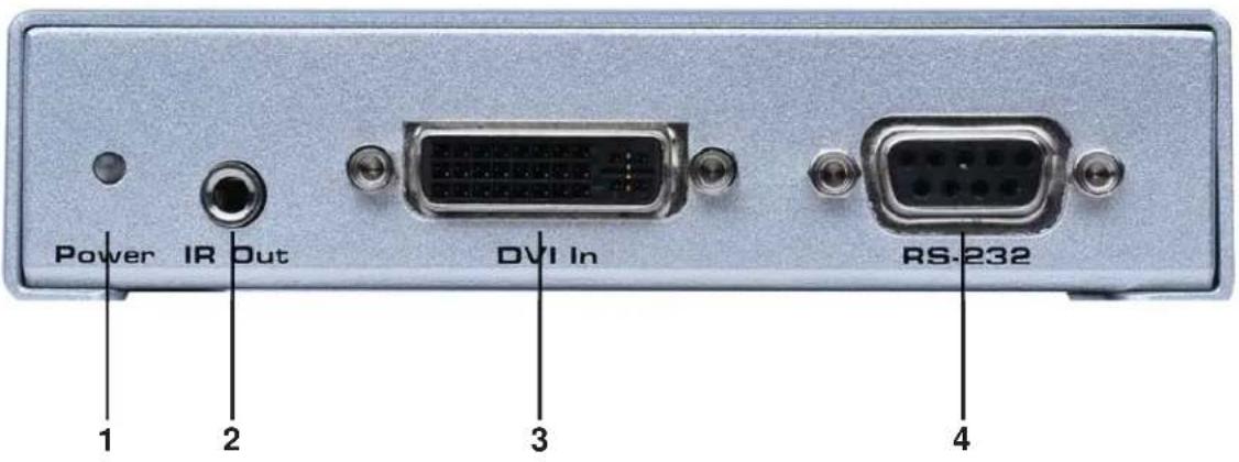
text_image
Power IR Out DVI In RS-232 1 2 3 4Back Panel

text_image
CAT-5 FIBER 5V DC 5 6 71 LED Power Indicator
This LED will become active once the included 5V DC power supply is properly connected between the sender and an open wall power socket.
2 IR Out (Blaster)
An optional IR transmitter/blaster (EXT-2IREMIT) connects to this output port. The IR blaster's IR emitter will need to be placed on or near the IR receiver of a device for proper relaying of commands from the receiver.
3 DVI-D Input
This receptacle will accept a DVI Single-Link source device.
4 RS-232 Serial Communications Input
This port is capable of 2-way serial communication between RS-232 devices connected to the sender and receiver. This port can be connected to a computer's serial communications port for interaction with a RS-232 serial communications device connected to the receiver.
5 RJ-45 Link Connector
This port is used to connect the sending and receiving units together for data traffic. Use a CAT-5, CAT-5e or CAT-6 cable. When field terminating cable please adhere to the TIA/EIA-568-B specification (page 9).
6 Fiber Optic Connector (Multi-Mode SC Type)
This connector accepts 1 strand of SC terminated fiber optic cable that will link the sending and receiving unit together. The DVI RS-232 over Fiber system will only accept multi-mode fiber optic cabling.
7 Locking 5V DC Power Input
Connect the included 5V DC power supply to this input. The Power LED will become active when the 5V DC power supply has been properly connected to the unit and an open wall power socket. This receptacle features a locking connector for a secure connection.
Front Panel
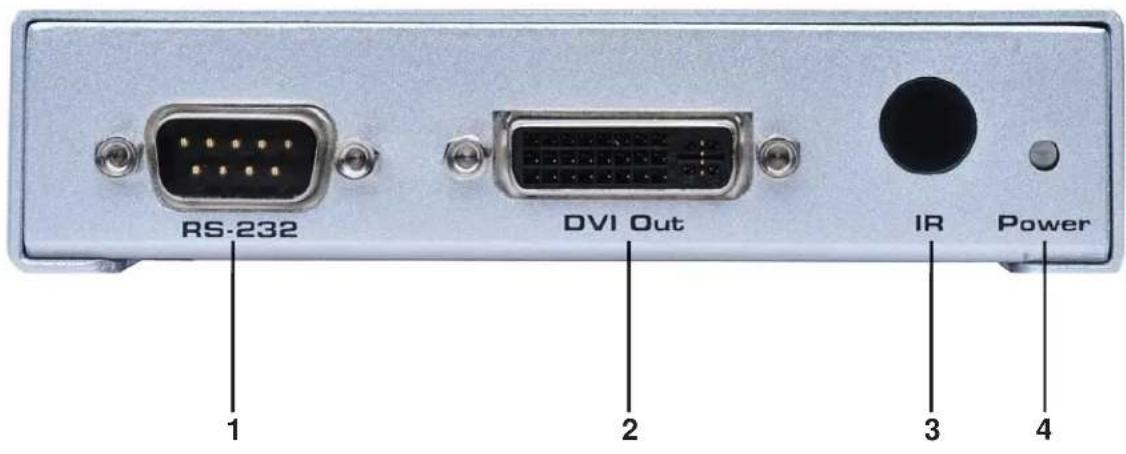
text_image
RS-232 DVI Out IR Power 1 2 3 4Back Panel

text_image
5V DC Ext-IR FIBER CAT-5 5 6 7 81 RS-232 Serial Communications Input
This port is capable of 2-way serial communication between RS-232 devices connected to the sender and receiver. This port can be connected to a computer's serial communications port for interaction with a RS-232 serial communications device connected to the receiver.
2 DVI-D Output
This receptacle will accept a DVI capable Single-Link output device.
3 Infrared (IR) Receiver
This IR receiver will relay IR commands from the receiving unit to the sending unit for output to a IR transmitter (blaster) on a IR controllable device.
4 LED Power Indicator
This LED will become active once the included 5V DC power supply is properly connected between the receiver and an open wall power socket.
5 Locking 5V DC Power Input
Connect the included 5V DC power supply to this input. The Power LED will become active when the 5V DC power supply has been properly connected to the unit and an open wall power socket. This receptacle features a locking connector for a secure connection.
6 Infrared (IR) Receiver Extension Port
This port will accept an optionally purchased IR extension cable (Gefen part#EXT-RMT-EXTIR). This is useful for installations where the IR receiver, located on the front panel (Item 2 on this page), is not in line-of-sight with the IR remote control used to relay commands to the device at the sender's location.
7 Fiber Optic Connector (Multi-Mode SC Type)
This connector accepts 1 strand of SC terminated fiber optic cable that will link the sending and receiving unit together. The DVI RS-232 over Fiber system will only accept multi-mode fiber optic cabling.
8 RJ-45 Link Connector
This port is used to connect the sending and receiving units together for data traffic. Use a CAT-5, CAT-5e or CAT-6 cable. When field terminating cable please adhere to the TIA/EIA-568-B specification (page 9).
How to Connect the DVI RS-232 over Fiber
- Connect the Single-Link DVI-D source to the DVI RS-232 over Fiber sending unit's DVI input port using the supplied DVI cable.
- Connect the RS-232 source to the DVI RS-232 over Fiber sending unit's RS-232 input port using the supplied DB-9 serial cable.
- For IR repeater functionality, please connect the IR emitter's mini-jack (sold separately, part # EXT-2IREMIT) into the DVI RS-232 over Fiber sending unit. Place the IR emitter directly on or above the IR receiver of the desired source device.
- Connect the DVI RS-232 over Fiber sending and receiving units together using one user supplied SC terminated multi-mode fiber optic cable and one CAT-5, CAT-5e or CAT-6 cable.
NOTE: If field terminating network cable, please adhere to the TIA/EIA568B specification. Please see page 9 for more information.
-
Connect the DVI-D capable output device to the DVI output port of the DVI RS-232 over Fiber receiving unit using a user supplied DVI-D cable.
-
Connect the RS-232 device to the RS-232 output port of the DVI RS-232 over Fiber receiving unit using a user supplied DB-9 serial cable.
-
Plug the included 5V DC power supplies into both the DVI RS-232 over Fiber sending and receiving units.
-
Power on the display first and the source second.

natural_image
3D cutaway illustration of an Ethernet cable connector showing internal components and casing (no text or symbols)Gefen has specifically engineered their products to work with the TIA/EIA-568-B specification. Please adhere to the table below when field terminating cable for use with Gefen products. Failure to do so may produce unexpected results and reduced performance.
| Pin Color |
| 1 Orange / White |
| 2 Orange |
| 3 Green / White |
| 4 Blue |
| 5 Blue / White |
| 6 Green |
| 7 Brown / White |
| 8 Brown |
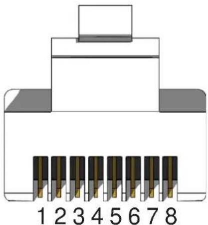
natural_image
Diagram of an 8-pin connector with pin numbering from 1 to 8 (no text or symbols on the diagram itself)CAT-5, CAT-5e, and CAT-6 cabling comes in stranded and solid core types. Gefen recommends using solid core cabling. CAT-6 cable is also recommended for best results.
Each cable run must be one continuous run from one end to the other. No splices or use of punch down blocks.
Video Amplifier Bandwidth 165 MHz
Input Video Signal 1.2 Volts p-p
Input DDC Signal 5 Volts p-p (TTL)
Single Link Range 1080p/1920 x 1200
DVI I/O Connectors ...... DVI-I (29 pin) female (digital only)
RS232 Input Connector ...... DB-9 female
RS232 Output Connector .... DB-9 male
Power Supply 5V DC
Power Consumption 20 Watts (max)
Link Connector RJ-45
Video Link Connector .... SC
Serial Communication Standard: RS-232 standards
HDCP...... Compliant
Dimensions 4.75"W x 1.125"H x 3.375"D
Shipping Weight 5 lbs.