N5200XXX - NAS Origin Storage - Free user manual and instructions
Find the device manual for free N5200XXX Origin Storage in PDF.

User questions about N5200XXX Origin Storage
0 question about this device. Answer the ones you know or ask your own.
Ask a new question about this device
Download the instructions for your NAS in PDF format for free! Find your manual N5200XXX - Origin Storage and take your electronic device back in hand. On this page are published all the documents necessary for the use of your device. N5200XXX by Origin Storage.
USER MANUAL N5200XXX Origin Storage
natural_image
Exterior view of a silver industrial electronic device with control panel and display (no visible text or symbols)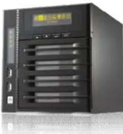
natural_image
Front view of a black server rack unit with multiple ventilation grilles and a digital display (no visible text or symbols)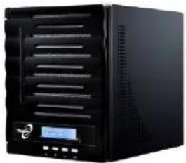
natural_image
Black desktop computer tower with ventilation slots and a digital display (no visible text or labels)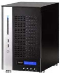
natural_image
Front view of a black server rack with ventilation grilles and a digital display (no visible text or labels)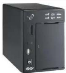
natural_image
Black desktop computer tower with ports and indicator lights (no visible text or labels)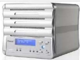
natural_image
Exterior view of a modern office building (no signage)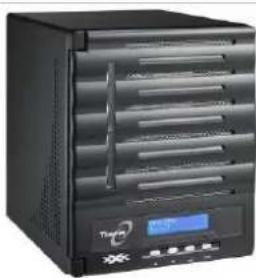
natural_image
Black TP5892 dual-chamber electronic device with ventilation slots and a digital display (no visible text or symbols on the device body)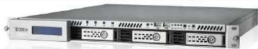
natural_image
Front view of a server rack unit with multiple ports and a digital display (no visible text or labels)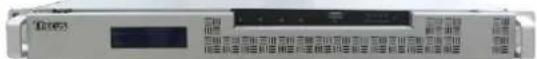
natural_image
Front view of a black Tacos rack unit with ventilation grilles and indicator lights (no readable text or symbols)
natural_image
Front view of a black server rack unit with ventilation fans and drive bays (no visible text or labels)Thecus
N3200XXX/N0503
N4200 series
N5200XXX/N5500
1U4200XXX/1U4600
N7700 series
N2200XXX
N8200XXX/N8800 series
User's Manual
Copyright and Trademark Notice
Thecus and other names of Thecus products are registered trademarks of Thecus Technology Corp. Microsoft, Windows, and the Windows logo are registered trademarks of Microsoft Corporation. Apple, iTunes and Apple OS X are registered trademarks of Apple Computers, Inc. All other trademarks and brand names are the property of their respective owners. Specifications are subject to change without notice.
Copyright © 2011 Thecus Technology Corporation. All rights reserved.
About This Manual
All information in this manual has been carefully verified to ensure its correctness. In case of an error, please provide us with your feedback. Thecus Technology Corporation reserves the right to modify the contents of this manual without notice.
Product name:
Thecus N2200XXX/N3200XXX/N0503/N4200 series
/N5200XXX/N5500/1U4200XXX/1U4600/N7700 series/N8800 series/N8200XXX
Manual Version: 6.2
Release Date: May 2011
Limited Warranty
Thecus Technology Corporation guarantees all components of Thecus NAS products are thoroughly tested before they leave the factory and should function normally under general usage. In case of any system malfunctions, Thecus Technology Corporation and its local representatives and dealers are responsible for repair without cost to the customer if the product fails within the warranty period and under normal usage. Thecus Technology Corporation is not responsible for any damage or loss of data deemed to be caused by its products. It is highly recommended that users conduct necessary back-up practices.
Safety Warnings
For your safety, please read and follow the following safety warnings:
Read this manual thoroughly before attempting to set up your Thecus IP storage.
Your Thecus IP storage is a complicated electronic device. DO NOT attempt to repair it under any circumstances. In the case of malfunction, turn off the power immediately and have it repaired at a qualified service center. Contact your vendor for details.
DO NOT allow anything to rest on the power cord and DO NOT place the power cord in an area where it can be stepped on. Carefully place connecting cables to avoid stepping or tripping on them.
Your Thecus IP storage can operate normally under temperatures between 5°C and 40°C, with relative humidity of 20% – 85%. Using Thecus IP storage under extreme environmental conditions could damage the unit.
Ensure that the Thecus IP storage is provided with the correct supply voltage (AC 100V \~ 240V, 50/60 Hz). Plugging the Thecus IP storage to an incorrect power source could damage the unit.
Do NOT expose Thecus IP storage to dampness, dust, or corrosive liquids.
Do NOT place Thecus IP storage on any uneven surfaces.
DO NOT place Thecus IP storage in direct sunlight or expose it to other heat sources.
DO NOT use chemicals or aerosols to clean Thecus IP storage. Unplug the power cord and all connected cables before cleaning.
DO NOT place any objects on the Thecus IP storage or obstruct its ventilation slots to avoid overheating the unit.
Keep packaging out of the reach of children.
If disposing of the device, please follow your local regulations for the safe disposal of electronic products to protect the environment.
Table of Contents
Copyright and Trademark Notice 2
About This Manual.... 2
Limited Warranty 2
Safety Warnings.... 3
Table of Contents...... 4
Chapter 1: Introduction......7
Overview 7
Product Highlights....7
Package Contents....9
Front Panel....10
Hard Disk Trays....19
Rear Panel....22
Chapter 2: Hardware Installation .... 31
Overview 31
Before You Begin....31
Cable Connections 31
Chapter 3: First Time Setup.... 38
Overview 38
Thecus Setup Wizard....38
LCD Operation (N5200XXX/N5500/1U4200XXX/1U4600/N7700 series/N8200XXX/N8800 series)....40
LCD Operation (N3200XXX/N0503)....42
OLED Operation (N4200 series) 43
Typical Setup Procedure 44
Chapter 4: System Administration 46
Overview 46
Web Administration Interface ....46
My Favorite....47
Menu Bar....49
Message Bar 50
System Information....51
General Information....51
System/Service Status 51
Logs....52
On-line Register 53
Syslog Management.... 54
System Management....55
Date and Time: System Date and settings 55
Notification configuration 56
Firmware Upgrade 57
Schedule Power On/Off.... 57
Administrator password.... 58
Config Mgmt 59
Factory default 60
Reboot & Shutdown 60
File System check....60
Wake-Up On LAN (WOL).... 62
SNMP Support 62
UI Login Configuration....63
System Network....63
WAN/LAN1....63
LAN2....65
DHCP Server Configuration 66
Storage Management....66
Disks Information 66
RAID Information....69
Space Allocation 79
iSCSI Thin-Provisioning 84
Advance Option 88
Stackable NAS....89
ISO Mount 95
Share Folder 98
Folder and sub-folders Access Control List (ACL)....103
User and Group Authentication....106
ADS/NT Support....106
Local User Configuration.... 108
Local Group Configuration.... 110
Batch Create Users and Groups 112
Quota.... 113
Network Service....114
Samba / CIFS.... 114
AFP (Apple Network Setup) 115
NFS Setup 116
FTP 116
TFTP 117
HTTP/ Web Disk.... 117
UPnP 118
Bonjour Setting 118
Application Server....119
iTunes® Server 119
Module Installation.... 119
Auto Module Installation 120
Backup 121
Nsync (Does not apply to the 3x series).... 121
Nsync Target (Does not apply to the 3X series).... 124
Dual DOM (Not available on N3200XXX/N0503/N4200Eco/N7700/N8800 NAS) ..... 124
Rsync Target(For the 3x series) 125
Rsync (For the 3x series)....126
Thecus Backup Utility 127
Windows XP Data Backup 128
Apple OS X Backup Utilities.... 129
External Device....129
Printer Information 129
UPS Setting 135
Chapter 5: Using Thecus IP Storage.... 136
Overview 136
Login Page....136
Using the Web Disk (Does not apply to the 3X series' Web Disk)....136
Photo Server (Does not apply to the 3X series' photo server)....139
Windows XP Publishing Wizard 139
Managing Albums and Photos.... 145
Creating Albums 146
Password Protecting Albums.... 146
Uploading Pictures to Albums 146
EXIF Information 146
Slide Shows 147
Mapping a Client PC to the Thecus IP Storage ....147
Windows.... 147
Apple OS X 148
Mapping Thecus IP storage as an iSCSI Drive....148
Windows 2000/XP....149
Windows Vista.... 153
Chapter 6: Tips and Tricks .... 153
USB and eSATA Storage Expansion....153
Adding a Spare Disk ....153
Remote Administration....153
Part I - Setup a DynDNS Account.... 154
Part II - Enable DDNS on the Router 154
Part III - Setting up Virtual Servers (HTTPS).... 154
Firewall Software Configuration....154
Replacing Damaged Hard Drives....155
Hard Drive Damage 155
Replacing a Hard Drive.... 155
RAID Auto-Rebuild 155
Chapter 7: Troubleshooting.... 156
Forgot My Network IP Address ....156
Can't Map a Network Drive in Windows XP....156
Restoring Factory Defaults....156
Problems with Time and Date Settings ....157
Dual DOM Supports for Dual Protection ....157
Appendix A: Customer Support.... 158
Appendix B: RAID Basics 159
Overview....159
Benefits....159
Improved Performance 159
Data Security 159
RAID Levels....159
Appendix C: Active Directory Basics.... 162
Overview....162
What is Active Directory? 162
ADS Benefits....162
Appendix D: Licensing Information.... 163
Overview....163
Source Code Availability 163
CGIC License Terms....164
GNU General Public License....164
Chapter 1: Introduction
Overview
Thank you for choosing the Thecus IP Storage Server. The Thecus IP storage is an easy-to-use storage server that allows a dedicated approach to storing and distributing data on a network. Data reliability is ensured with RAID features that provide data security and recovery—over multiple Terabyte of storage are available using RAID 5 and RAID 6 (depending on model). Gigabit Ethernet ports enhance network efficiency, allowing Thecus IP storage to take over file management functions, increase application and data sharing and provide faster data response. The Thecus IP storage offers data mobility with a disk roaming feature that lets you swap working hard drives for use in other Thecus IP storage, securing the continuity of data in the event of hardware failure. The Thecus IP storage allows data consolidation and sharing between Windows (SMB/CIFS), UNIX/Linux, and Apple OS X environments. The Thecus IP storage's user-friendly GUI supports multiple Languages.
Product Highlights
File Server
First and foremost, the Thecus IP storage allows you to store and share files over an IP network. With a Network Attached Storage (NAS) device, you can centralize your files and share them easily over your network. With the easy-to-use web-based interface, users on your network can access these files in a snap.
To learn about the Web User Interface, go to
Chapter 5: Using the Thecus IP Storage > Using WebDisk.
FTP Server
With the built-in FTP Server, friends, clients, and customers can upload and download files to your Thecus IP storage over the Internet with their favorite FTP programs. You can create user accounts so that only authorized users have access.
To set up the FTP Server, refer to
Chapter 4: System Administration>Network service> FTP .
iTunes Server
With the built-in iTunes server capability, the Thecus IP storage enables digital music to be shared and played anywhere on the network!
To set up the iTunes Server, refer to
Chapter 4: Application Server>iTunes Configuration.
Backup Server
Don't leave precious data to chance. With advanced backup capabilities, you can easily upload mission critical files to the Thecus IP storage, and even automate your backup tasks for true peace-of-mind.
To find out how to backup your files with the Thecus IP storage, refer to
Chapter 4: Backup > Nsync. (Does not apply to the 3x series)
Printer Server
With the Thecus IP storage's Printer Server, you can easily share an IPP printer with other PCs connected to your network.
To set up the Printer Server, refer to
Chapter 4: External Device>Printer Information.
Multiple RAID
Thecus IP storage supports multiple RAID volumes on one system. So, you can create RAID 0 for your non-critical data, and create RAID 1,5 or 6 (depend on model) for mission-critical data. Create the RAID levels depending on your needs.
To configure RAID modes on the Thecus IP storage, refer to
Chapter 4: Storage Management >RAID Information.
iSCSI Capability
Thecus IP storage is not only a file server, but it also supports iSCSI initiators. Your server can access Thecus IP storage as a direct-attached-storage over the LAN or Internet. There is no easier way to expand the capacity of your current application servers. All the storage needs can be centrally managed and deployed. This brings ultimate flexibility to users.
To set up an iSCSI volume, refer to
Chapter 4: Storage Management > Space Allocation > Allocating Space for iSCSI Volume.
Superior Power Management
Thecus IP storage supports schedule power on/off. With this feature, administrator can set at what time to turn on or off the system. This feature is a big plus for people who want to conserve energy. Wake-On-LAN enables administrator to remotely turn on the system without even leaving their own seat.
To schedule system on and off, refer to
Chapter 4: System Management> Scheduled Power On/Off
Package Contents
The Thecus IP storage should contain the following common items:
- System Unit x1
● QIG (Quick Installation Guide) x1
● CD-Title x3 (Acronics backup CD, Twonky media server CD & Universal CD) - Ethernet Cable x1
- Accessory bag x1
- HDD Compatibility list Card x1
● Multiple Languages Warranty Card x1 - Power cord x1
Your N3200XXX package should contain additional items:
- 3.5" HDD rail x6
● Power Adaptor + Power cord x1
Your N0503 package should contain additional items:
- 3 to 5 HDD cage x1 (Installed)
- 3.5" HDD rail x6
● Power Adaptor + Power cord x1
Your N4200 series package should contain additional items:
● Power adapter + Power cordx1
Your N5500 package should contain additional items:
- USB Cable (A-B Type) x1
Your 1U4200XXX package should contain additional items:
- Power Cord
■ 1U4200XXXRx1
Your 1U4600 package should contain additional items:
- Power Cord
■ 1U4600Rx1 - USB Cable (A-B Type) x1
Your N8800/N8200XXX series package should contain additional items:
- Power Cord x1
Please check to see if your package is complete. If you find that some items are missing, contact your dealer.
Front Panel
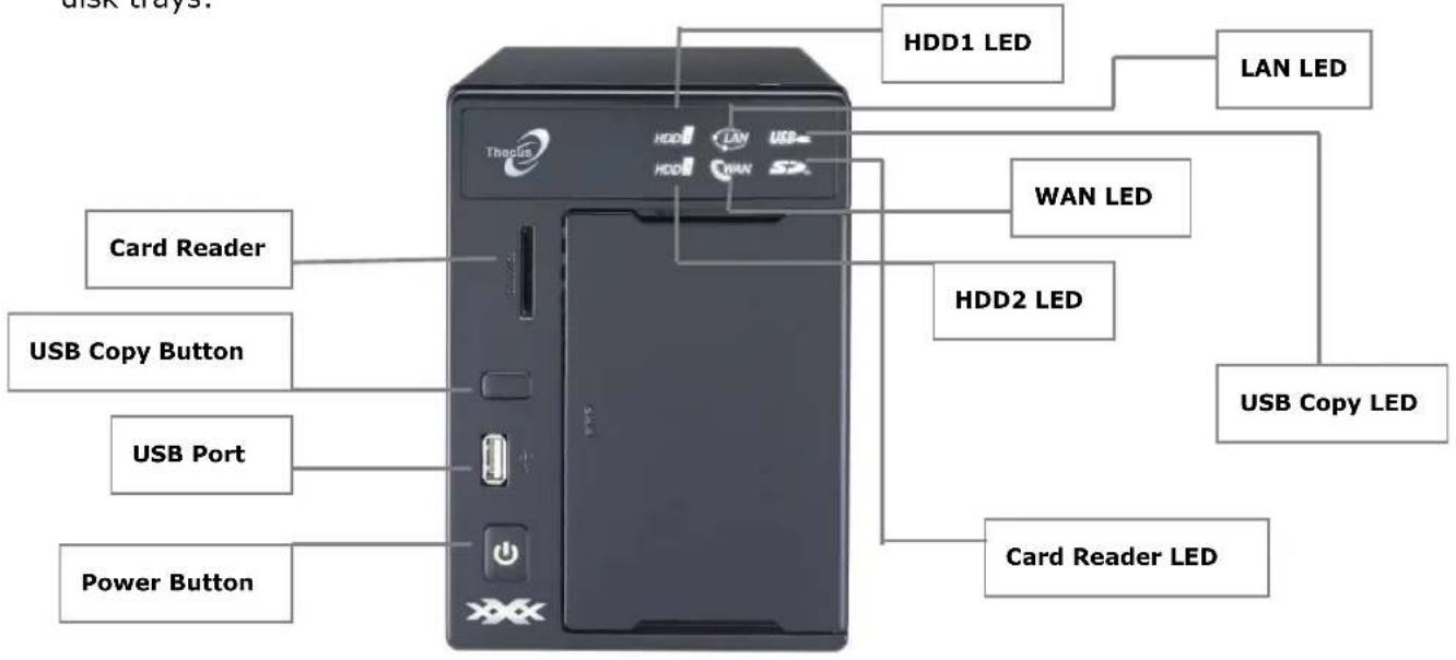
N2200XXX:
The Thecus N2200XXX's front panel has the device's controls, indicators, and hard disk trays:
| Front Panel | |
| Item Description | |
| Power Button • Powers the N2200XXX on/off. | |
| USB Port | • USB 2.0 port for compatible USB devices, such as digital cameras, USB disks, and USB printers. |
| USB Copy Button • Copies USB storage contents to N2200XXX. | |
| Card reader • Supports SD/SDHC/MMC cards via USB interface. | |
| HDD1 led | • Blinking white: HDD activity |
| HDD2 led | • Blinking white: HDD activity |
| WAN led | • Solid white: WAN Cable link• Blinking white: Network activity |
| LAN led | • Solid white: LAN Cable link• Blinking : Network activity |
| USB Copy led | • Blinking white: USB copy activity |
| Card reader led | • Blinking white: Card reader copy activity |
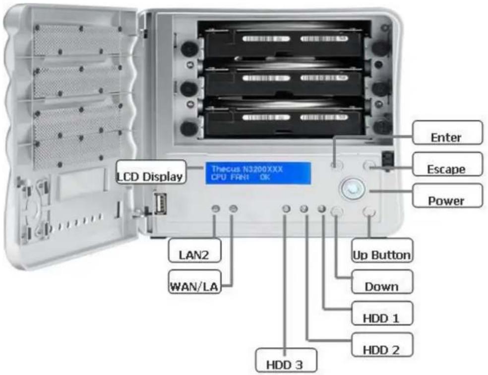
N3200XXX:
The Thecus N3200XXX's front panel has the device's controls, indicators, and hard disk trays:
| Front Panel | |
| Item Description | |
| Power LED | Solid blue: System is powered on |
| WAN/LAN1 LED | Solid green: Network linkBlinking orange: Network activity |
| LAN2 LED | Solid green: Network linkBlinking orange: Network activity |
| HDD 1 LED | Solid red: HDD failedBlinking orange: HDD activity |
| HDD 2 LED | Solid red: HDD failedBlinking orange: HDD activity |
| HDD 3 LED | Solid red: HDD failedBlinking orange: HDD activity |
| USB Port | USB 2.0 port for compatible USB devices, such as digital cameras, USB disks, and USB printers. |
| Power Button • Powers the N3200XXX on/off.Solid blue: Device is powered on | |
| LCD Display | Displays current system status and messages (Update time: 60 seconds). |
| Down Button ▼ | Push to scroll DOWN when using the LCD display. |
| Up Button ▲ | Push to scroll UP when using the LCD display. |
| Enter Button ↓ | Push to confirm information entered into the LCD display. |
| Escape Button ESC | Push to leave the current LCD menu. |
N0503:
The Thecus N0503's front panel has the device's controls, indicators, and hard disk trays:
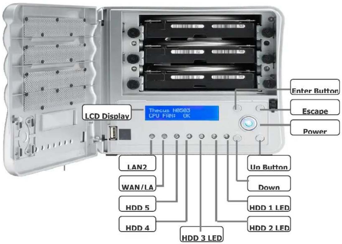
| Front Panel | |
| Item Description | |
| Power LED | Solid blue: System is powered on |
| WAN/LAN1 LED | Solid green: Network linkBlinking orange: Network activity |
| LAN2 LED | Solid green: Network linkBlinking orange: Network activity |
| HDD 1 LED | Solid red: HDD failedBlinking orange: HDD activity |
| HDD 2 LED | Solid red: HDD failedBlinking orange: HDD activity |
| HDD 3 LED | Solid red: HDD failedBlinking orange: HDD activity |
| HDD 4 LED | Solid red: HDD failedBlinking orange: HDD activity |
| HDD 5 LED | Solid red: HDD failedBlinking orange: HDD activity |
| USB Port | USB 2.0 port for compatible USB devices, such as digital cameras, USB disks, and USB printers. |
| Power Button • Powers the N0503 on/off.Solid blue: Device is powered on | |
| LCD Display | Displays current system status and messages (Update time: 60 seconds). |
| Down Button ▼ | Push to scroll DOWN when using the LCD display. |
| Up Button ▲ | • Push to scroll UP when using the LCD display. |
| Enter Button ↓ | • Push to confirm information entered into the LCD display. |
| Escape Button ESC | • Push to leave the current LCD menu. |
N4200 series:
The Thecus N4200 series front panel has the device's controls, indicators, and hard disk trays:
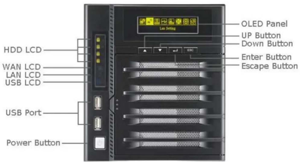
| Front Panel | ||
| Item Description | ||
| Power Button | • Power on/off N4200series | |
| OLED • Displays current system status and messages• OLED screen saver will be enabled after screen is left idle for more than 3 mins• OLED screen will be diabled after it is left idle for more than 6 mins | ||
| OLED | HDD 1 LED | • Yellow: HDD activity• Red: HDD failure |
| HDD 2 LED | • Yellow: HDD activity• Red: HDD failure | |
| HDD 3 LED | • Yellow: HDD activity• Red: HDD failure | |
| HDD 4 LED | • Yellow: HDD activity• Red: HDD failure | |
| WAN/LAN1 LED | • Blinking green: network activity | |
| LAN2 LED | • Blinking green: network activity | |
| USB Copy . Blue: USB Copy activity• Red: USB Copy failure | ||
| HDD Tray • Four HDD trays support 4x 3.5" or 4 x 2.5" HDDs | ||
| USB Copy Button | • Copies USB storage contents to the N4200 series. | |
| USB Port | • USB 2.0 port for compatible USB devices, such as USB disks. | |
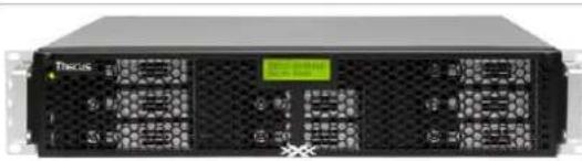
N5200XXX/N5500:
The Thecus N5500 front panel has the device's controls, indicators, and hard disk trays:
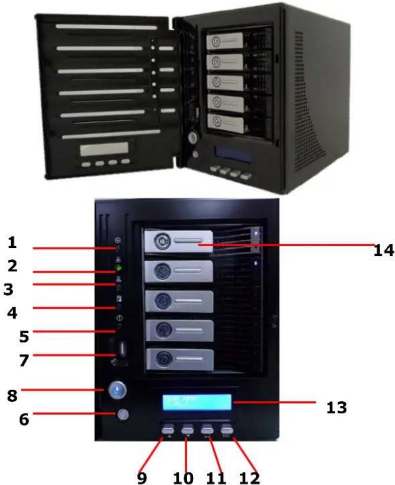
| Front Panel | |
| Item Description | |
| 1.System LED | Blinking orange: System is being upgraded or ;is starting up; data currently inaccessible |
| 2.WAN/LAN1 LED | Solid green: Network linkBlinking green: Network activity |
| 3.LAN2 LED | Solid green: Network linkBlinking green: Network activity |
| 4.USB Copy LED | Solid blue: Files are being copied from a USB storage device |
| 5.Syetem Warning LED | Solid RED: System error |
| 6.Reset Button • Resets | system configuration to default value. |
| 7.USB Port | USB 2.0 port for compatible USB devices, such as USB disks. |
| 8.Power Button/ Power LED | Power on/off N5200XXX/N5500 and Power LED.Solid blue: System is power on. |
| 9.Up Button ▲ | Push to scroll up when using the LCD display. |
| 10.Down Button ▼ | Push to enter the USB copy operation screen. |
| 11.Enter Button ↩ | Push to enter LCD administrator password to access basic system setting. |
| 12.Escape Button ESC | Push to leave the current LCD menu. |
| 13.LCD Display | Displays current system status and warning messages. |
| 14.HDD Trays • Five 3.5" | SATA HDD trays.Locks are provided for added security. |
N7700 Series:
The Thecus N7700 series front panel has the device's controls, indicators, and hard disk trays:

| Front Panel | |
| Item Description | |
| 1.Power LED | Solid blue: System is power on. |
| 2.System LED | Solid orange: system is being upgraded or system startup; data currently inaccessible |
| 3.WAN/LAN1 LED | Solid green: network linkBlinking green: network activity |
| 4.LAN2 LED | Solid green: network linkBlinking green: network activity |
| 5.USB Copy LED | Solid blue: files are being copied from a USB storage device |
| 6.eSATA link LED | Solid blue: external eSATA device has connected |
| 7.USB Port | USB 2.0 port for compatible USB devices, such as USB disks. |
| 8.Power Button | Power on/off N7700 |
| 9.Up Button ▲ | Push to scroll up when using the LCD display |
| 10.Down Button ▼ | Push to enter USB copy operation screen |
| 11.Enter Button ↓ | Push to enter LCD operate password for basic system setting |
| 12.Escape Button ESC | Push to leave the current LCD menu |
| 13.LCD Display • Displays current system status and warning messages | |
| 14.HDD Trays • Seven 3.5” SATA HDD traysLocks are provided for added security | |
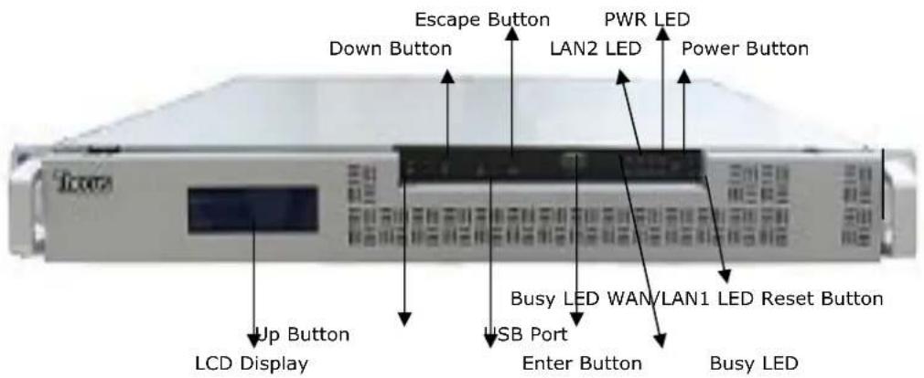
1U4200XXX:
The Thecus 1U4200XXX front panel has the device's controls, indicators, and hard disk trays:
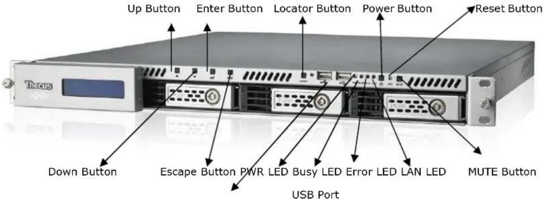
Front Panel
| Item Description | |
| LCD Display | Displays the current system status and warning messages.Displays hostname, WAN/LAN1/LAN2 IP addresses, RAID status, and current time. |
| Up Button ▲ | Push to scroll up when using the LCD display. |
| Down Button ▼ | Push to scroll down when using the LCD display. |
| Enter Button ↓ | Push to confirm information entered into the LCD display. |
| Escape Button ESC | Push to leave the current LCD menu. |
| Locator Button | Turns on the LED backlight. |
| USB Port | USB 2.0 port for compatible USB devices, such as digital cameras, USB disks, and USB printers. |
| PWR LED | Solid Blue: System is powered on. |
| Busy LED | Blinking orange: system startup or system maintenance; data currently inaccessible |
| Error LED | Solid Red: System alert: Redundant power or system fan failure |
| LAN LED | Solid green: network linkBlinking green: network activity |
| Power Button | Power the 1U4200XXX on/off. |
| Reset Button | Resets the 1U4200XXX. |
| Mute Button | Mutes the system fan alarm (Can also be managed through the UI) |
| HDD Trays | Four 3.5” SATA HDD trays.Locks are provided for added security. |
1U4600:
The Thecus 1U4600 front panel has the device's controls, indicators, and hard disk trays:
| Front Panel | |
| Item Description | |
| WAN/LAN1 LED | Solid green: network linkBlinking green: network activity |
| LAN2 LED | Solid green: network linkBlinking green: network activity |
| Busy LED | Blinking orange: system startup or system maintenance; data currently inaccessible |
| USB Port | USB 2.0 port for compatible USB devices, such as digital cameras, USB disks, and USB printers |
| Power Button • Power on/off 1U4600Solid blue: Device is powered onBlinking blue: eSATA hard disk is connected and active | |
| Reset Button | Resets the 1U4600Press for five seconds during boot process to reset IP address and admin password |
| HDD Trays • Four 3.5" SATA HDD traysLocks are provided for added security | |
| LCD Display • Displays current system status and warning messagesDisplays hostname, WAN/LAN1/LAN2 IP address, RAID status, and current time | |
| Up Button ▲ | Push to scroll up when using the LCD display |
| Down Button ▼ | Push to scroll down when using the LCD display |
| Enter Button ↓ | Push to confirm information entered into the LCD display |
| Escape Button ESC | Push to leave the current LCD menu |
N8200XXX/N8800 series:
The Thecus N8200XXX/N8800 series front panel has the device's controls, indicators, and hard disk trays:
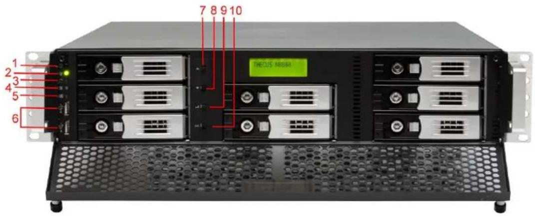
| Front Panel | |
| Item Description | |
| 1.Power Button • Power on/off N8200XXX/N8800 | |
| 2.Power LED | • Solid green: System is power on. |
| 3.Reboot Button • Press to system reboot | |
| 4.System fan alarm LED | • Solid red: system fan failure notification |
| 5. Mute button • Mute the system fan alarm. | |
| 6.USB Port | USB 2.0 port for compatible USB devices, such as USB disks, USB printers |
| 7.Up Button ▲ | • Push to scroll up when using the LCD display |
| 8.Down Button ▼ | • Push to enter USB copy operation screen |
| 9.Enter Button ↓ | • Push to enter LCD operate password for basic system setting |
| 10.Escape Button ESC | • Push to leave the current LCD menu |
Hard Disk Trays
1U4200XXX/N2200XXX/N8200XXX:
Each of above mentioned models' hard disk trays has a lock, a latch, and two LED indicators:
4 5
| Hard Disk Trays | |
| Item Description | |
| 1.HDD Power LED | Solid blue: Hard disk is powered on |
| 2.HDD Access/Error LED | Blinking green: System is accessing data on the hard diskSolid red: HDD fail |
| 3.Lock | Use the lock to physically secure the hard disk to the unit. |
| 4.Latch • Use to open and remove or close and secure the tray. | |
| 5.Handle • Pull to remove the HDD tray. | |
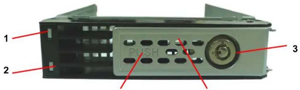
1U4600/N7700 series/N8800series:
Each of mentioned above models hard disk trays has a lock, a latch, and two LED indicators:
3 4 5
| Hard Disk Trays | |
| Item Description | |
| 1.HDD Power LED | Solid blue: Hard disk is powered on |
| 2.HDD Access/Error LED | Blinking green: System is accessing data on the hard diskSolid red: HDD fail |
| 3.Lock | Use the lock to physically secure the hard disk to the unit. |
| 4.Latch • Use to open and remove or close and secure the tray. | |
| 5.Handle • Pull to remove the HDD tray. | |
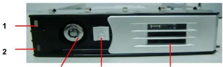
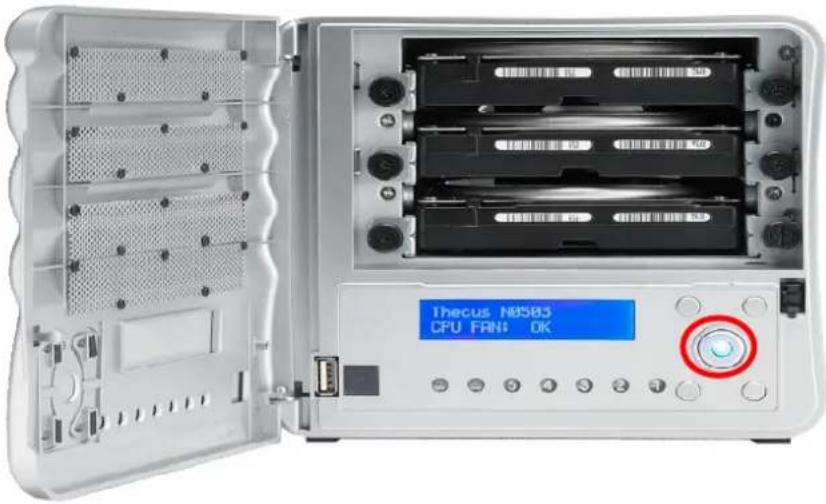
N4200 series/N5200XXX/N5500:
Each of the N5500's hard disk trays has a lock, a latch, and two LED indicators:
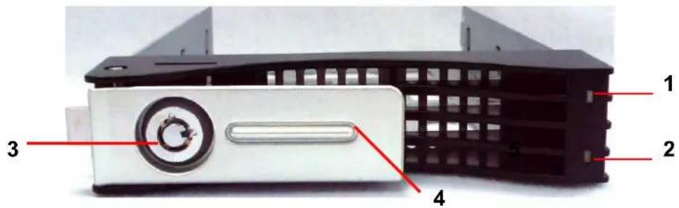
Hard Disk Trays
| Item Description | |
| 1.HDD Power LED | Solid blue: Hard disk is powered on(No function on N4200 series) |
| 2.HDD Access/Error LED | Blinking green: System is accessing data on the hard diskSolid red: HDD fail (No function on N4200 series) |
| 3.Lock | Use the lock to physically secure the hard disk to the unit. |
| 4.Handle • Pull to remove the HDD tray. | |
N3200XXX:
The N3200XXX only supports 3.5" Serial ATA (SATA) hard disks. To install a hard disk into the N3200XXX, follow the steps below:
- Open the front door of the N3200XXX.
- For 3.5" HDD:
a. Get the hard drive rails and place them on either side of the hard drive, fitting into the appropriate grooves.
b. Holding the hard drive rails in place, slide the hard disks into the N3200XXX until they snap into place.
c. Tighten the thumbscrews.
natural_image
Interior view of a silver-framed computer tower with open storage racks and drive bays (no visible text or labels)N0503:
The N0503 supports both 2.5" and 3.5" Serial ATA (SATA) hard disks. To install a hard disk into the N0503, follow the steps below:
-
Open front door of the N0503.
-
For 3.5" HDD
a. Get the hard drive rails and place them on either side of the hard drive, fitting into the appropriate grooves.
b. Holding the hard drive rails in place, slide the hard disks into the N0503 until they snap into place.
c. Tighten the thumbscrews.
- For 2.5" HDD
a. Remove the included 2.5" HDD tray.
b. Slide the 2.5" HDD into the 2.5" HDD cage.
c. Slide the 2.5" HDD cage back in until it snap into place.
- Replace the N0503 front cover.
natural_image
Three views of a silver server rack unit showing internal components and external casing (no visible text or labels)Rear Panel
N2200XXX:
The N2200XXX rear panel features ports and connectors.
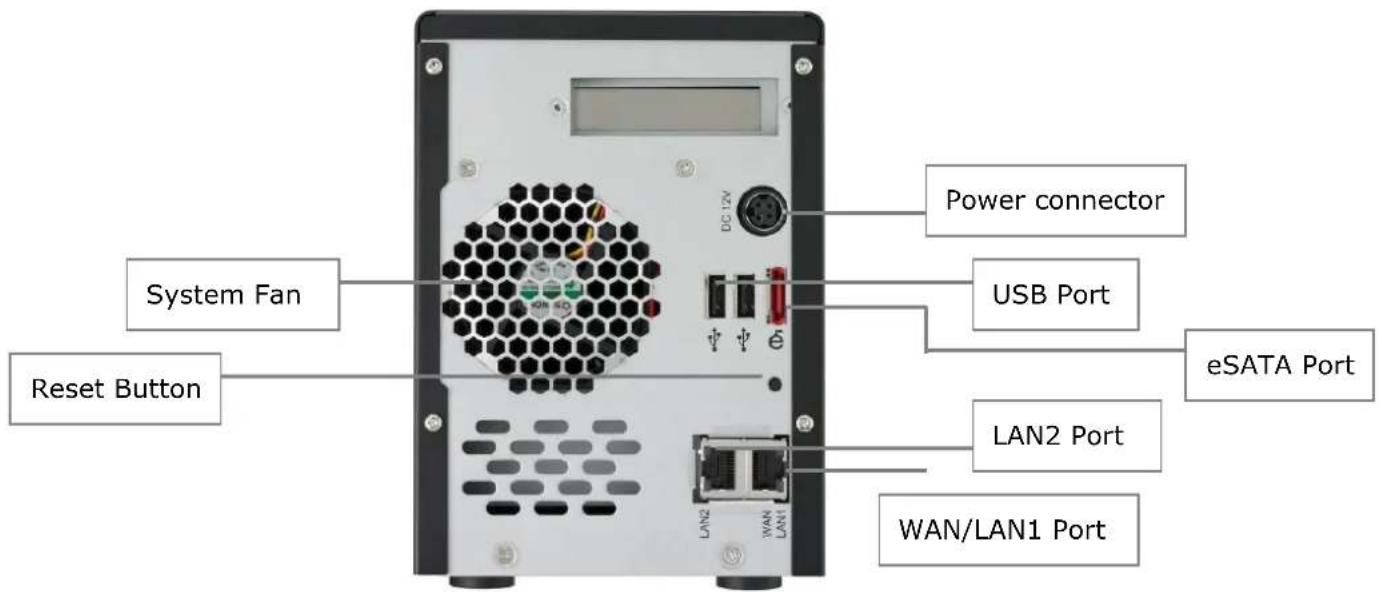
| Back Panel | |
| Item Description | |
| eSATA Port • eSATA | port for high-speed external storage expansion. |
| USB Port | • USB 2.0 port for compatible USB devices, such as digital cameras, USB disks, and USB printers. |
| WAN/LAN1 Port | • WAN/LAN1 port for connecting to an Ethernet network through a switch or a router. |
| LAN2 Port | • LAN2 port for connecting to a local Ethernet network through a switch or a router. |
| System Fan • System fan that exhausts heat from the unit. | |
| Power Connector | • Connect the included power cords to this connector. |
| Reset Button | • Resets the N2200XXX.• Pressing and holding the Reset button on the back for 5 seconds will reset your network setting and password, and turn off Jumbo Frame Support. |
N3200XXX/N0503:
The N3200XXX/N0503 rear panel features ports and connectors.
| Back Panel | |
| Item Description | |
| eSATA Port • eSATA | port for high-speed storage expansion |
| USB Port | • USB 2.0 port for compatible USB devices, such as digital cameras, USB disks, and USB printers |
| WAN/LAN1 Port | • WAN/LAN1 port for connecting to an Ethernet network through a switch or router |
| LAN2 Port • LAN2 port that can be used for connection sharing | |
| System Fan • System fan that exhausts heat from the unit | |
| Power Connector | • Connect the included power cords to these connectors |
| Reset Button | • Resets the N3200XXX/N0503• Immediately press and hold the Reset button on the back for 5 seconds. This will reset your network setting, password, and turn off Jumbo Frame Support. |
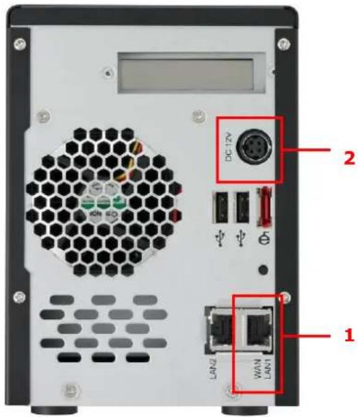
N4200 series:
The N4200 rear panel features ports and connectors.
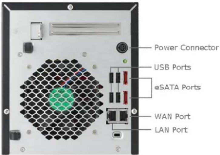
| Back Panel | |
| Item Description | |
| Power Connector | For connect the power adaptor |
| WAN/LAN1 Port | WAN/LAN1 port for connecting to an Ethernet network through a switch or router |
| LAN2 Port | LAN2 port for connecting to an Ethernet network through a switch or router |
| USB Ports | USB 2.0 ports for storage expansion |
| eSATA Ports | eSATA port for high-speed storage expansion |
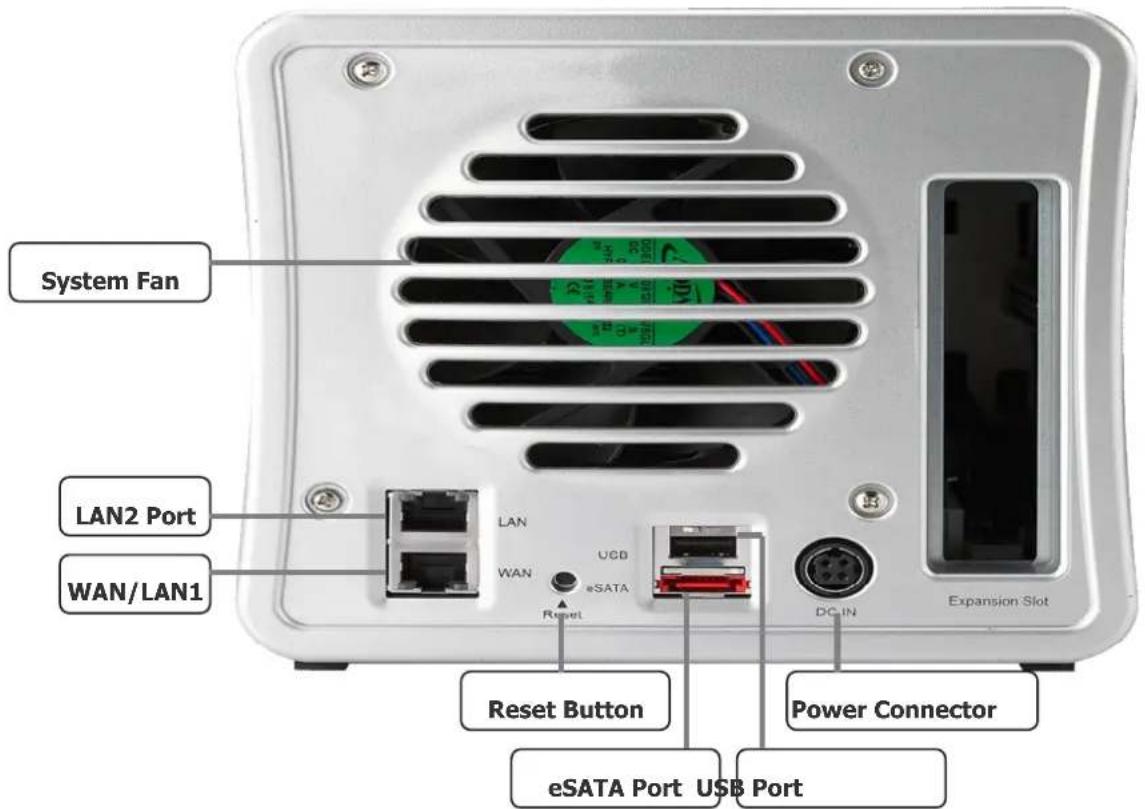
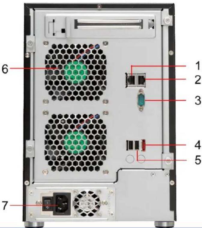
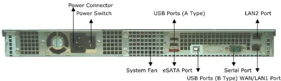
N5200XXX:
The N5200XXX rear panel features ports and connectors.
| Back Panel | |
| Item Description | |
| 1.WAN/LAN1 Port | • WAN/LAN1 port for connecting to an Ethernet network through a switch or a router. |
| 2.LAN2 Port | • LAN2 port for connecting to a local Ethernet network through a switch or router. |
| 3.Serial Port • This | port is for an external UPS device. |
| 4.eSATA Port • eSATA | port for high-speed external storage expansion. |
| 5.USB Port | • USB 2.0 port for compatible USB devices, such as USB disks and USB printers. |
| 6.System Fan • System fan that exhausts heat from the unit. | |
| 7.Power Connector | • Connect the included power cord to this connector. |
N5500:
The N5500 rear panel features ports and connectors.
| Back Panel | |
| Item Description | |
| 1.WAN/LAN1 Port | • WAN/LAN1 port for connecting to an Ethernet network through a switch or router. |
| 2.LAN2 Port | • LAN2 port for connecting to an Ethernet network through a switch or router. |
| 3.Serial Port • This port is for external UPS device. | |
| 4.eSATA Port • eSATA port for high-speed storage expansion. | |
| 5.USB Port (Type A) | • USB 2.0 port for compatible USB devices, such as USB disks, and USB printers. |
| 6.System Fan | • System fan that exhausts heat from the unit. |
| 7.Power Connector | • Connect the included power cord to this connector. |
| 8.USB Port (Type B) | • USB 2.0 port to connect PC (Type B of target mode). |
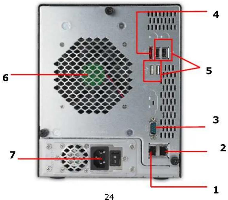
N7700 series:
The N7700 rear panel features ports and connectors.
| Back Panel | |
| Item Description | |
| 1.LAN2 Port | • LAN2 port for connecting to a local Ethernet network through a switch or router. |
| 2.WAN/LAN1 Port | • WAN/LAN1 port for connecting to an Ethernet network through a switch or router. |
| 3.Serial Port • This port is for an external UPS device. | |
| 4.eSATA Port • eSATA port for high-speed storage expansion. | |
| 5.USB Port | • USB 2.0 port for compatible USB devices, such as USB disks, and USB printers. |
| 6.System Fan • System fan that exhausts heat from the unit. | |
| 7.Power Connector | • Connect the included power cord to this connector. |
1U4200XXXR:
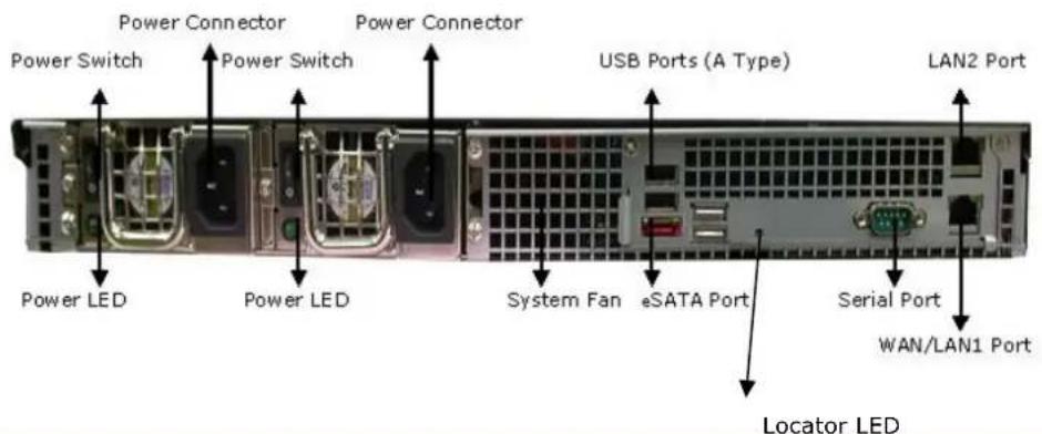
| 1U4200 Back Panel | |
| Item Description | |
| eSATA Port • eSATA | port for high-speed storage expansion. |
| USB Ports | • USB 2.0 ports for compatible USB devices, such as digital cameras, USB disks, and USB printers. |
| WAN/LAN1 Port | • WAN/LAN1 port for connecting to an Ethernet network through a switch or router. |
| LAN2 Port • LAN2 port that can be used for connection sharing. | |
| Power Switch • Switch for power supply. | |
| System Fan • System fan that exhausts heat from the unit. | |
| Serial Port • This port is for factory use only. | |
| Locator LED • Identifies each NAS within a rack mount configuration. | |
| Power Connector | • Connect the included power cords to these connectors. |
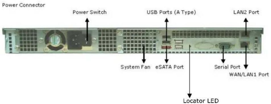
1U4200XXXS:
The rear panel of the 1U4200XXXS is similar to the 1U4200XXXR, but with a single power connector:
1U4600R:
The rear panel of the 1U4600R houses most of the USB and Ethernet connections, as well as the eSATA port, system fan, and power connector. See the table below for descriptions of each:
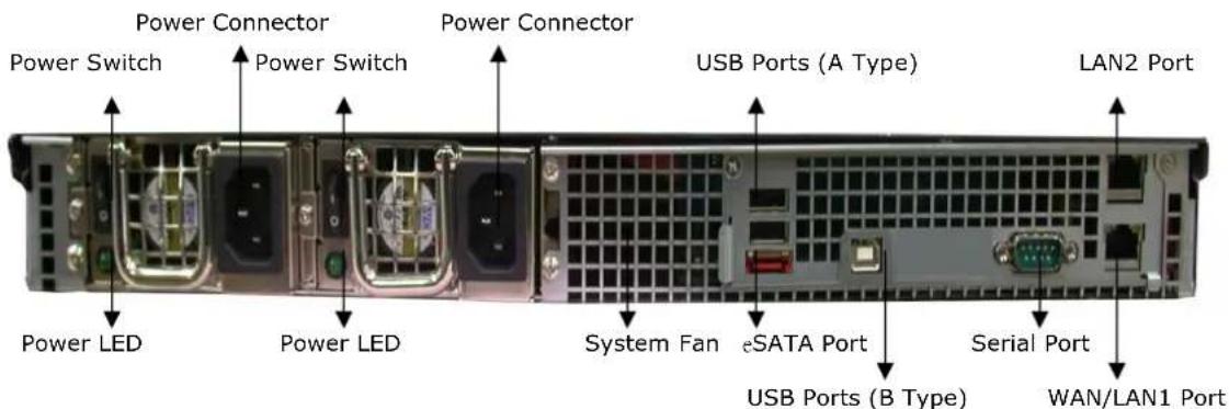
| 1U4600 Back Panel | |
| Item Description | |
| eSATA Port • eSATA | port for high-speed storage expansion |
| USB Ports | • USB 2.0 ports for compatible USB devices, such as digital cameras, USB disks, and USB printers |
| WAN/LAN1 Port | • WAN/LAN1 port for connecting to an Ethernet network through a switch or router |
| LAN2 Port • LAN2 port that can be used for connection sharing | |
| Power Switch • Switch for power supply | |
| System Fan • System fan that exhausts heat from the unit | |
| Serial Port • This port is for factory use only | |
| Power Connector | • Connect the included power cords to these connectors |
1U4600S:
The rear panel of the 1U4600S is similar to the 1U4600R, but with a single power connector:
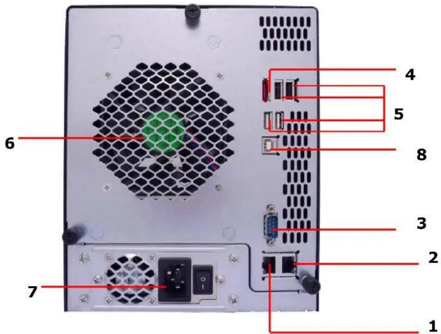
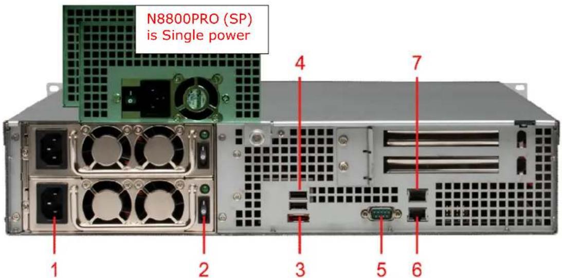
N8200XXX:
The N8200XXX rear panel features ports and connectors.
| Back Panel | |
| Item Description | |
| 1.Power Connector | Connect the included power cords to these connectors. |
| 2.Power Switch • Powers the N8200XXX on/off. | |
| 3.eSATA Port • eSATA port for high-speed storage expansion. | |
| 4.USB Port | USB 2.0 port for compatible USB devices, such as USB disks, and USB printers. |
| 5.Serial Port • This port is for an external UPS device. | |
| 6.WAN/LAN1 Port | WAN/LAN1 port for connecting to an Ethernet network through a switch or router. |
| 7.LAN2 Port | WAN/LAN1 port for connecting to a local Ethernet network through a switch or router. |
| 8. Locator LED | Identifies each NAS within a rack mount configuration. |
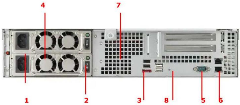
N8800 series:
The N8800 rear panel features ports and connectors.
| Back Panel | |
| Item Description | |
| 1.Power Connector | Connect the included power cords to these connectors |
| 2.Power Switch • Switch for power supply | |
| 3.eSATA Port • eSATA port for high-speed storage expansion | |
| 4.USB Port | USB 2.0 port for compatible USB devices, such as USB disks, and USB printers |
| 5.Serial Port • This port is for external UPS device | |
| 6.WAN/LAN1 Port | WAN/LAN1 port for connecting to an Ethernet network through a switch or router |
| 7.LAN2 Port | WAN/LAN1 port for connecting to an Ethernet network through a switch or router |
Chapter 2: Hardware Installation
Overview
Your Thecus IP storage is designed for easy installation. To help you get started, the following chapter will help you quickly get your Thecus IP storage up and running. Please read it carefully to prevent damaging your unit during installation.
Before You Begin
Before you begin, be sure to take the following precautions:
-
Read and understand the Safety Warnings outlined in the beginning of the manual.
-
If possible, wear an anti-static wrist strap during installation to prevent static discharge from damaging the sensitive electronic components on the Thecus IP storage.
-
Be careful not to use magnetized screwdrivers around the Thecus IP storage's electronic components.
Cable Connections
To connect the N2200XXX to your network, follow the steps below:
-
Connect an Ethernet cable from your network to the WAN/LAN1 port on the back panel of the N2200XXX.
-
Connect the provided power cord into the power socket on the back panel. Plug the other end of the cord into a surge protected socket.
- Press the power button to boot up the N2200XXX.
To connect the N3200XXX/N0503 to your network, follow the steps below:
- Connect an Ethernet cable from your network to the WAN/LAN1 port on the back panel of the N3200XXX/N0503.
- Connect the provided power cord into the power socket on the back panel. Plug the other end of the cord into a surge protected socket.
- Open the front door then press the power button to boot up the N3200XXX/N0503.
natural_image
Exterior view of a server rack unit with internal components and a digital display showing CPU status (no readable text or symbols beyond branding)To connect N4200 series NAS to your network, follow the steps below:
- Connect an Ethernet cable from your network to the WAN/LAN1 port on the back panel of the N4200.
natural_image
Close-up of a computer tower with a green hexagonal grid and red indicator lights (no text or symbols visible)- Connect the provided power cord into the universal power socket on the back panel. Plug the other end of the cord into a surge protected socket.
natural_image
Close-up of a black electrical plug with a green indicator light and three red connectors on the side (no visible text or symbols)- Press the power button on the Front Panel to boot up the N4200.
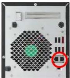
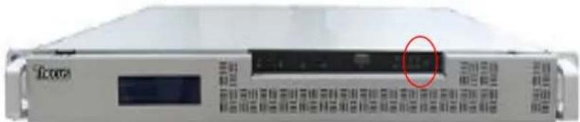
To connect the N5200XXX/N5500 to your network, follow the steps below:
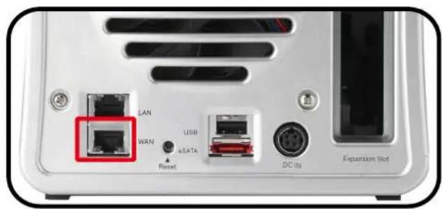
- Connect an Ethernet cable from your network to the WAN/LAN1 port on the back panel of the N5200XXX/N5500.
natural_image
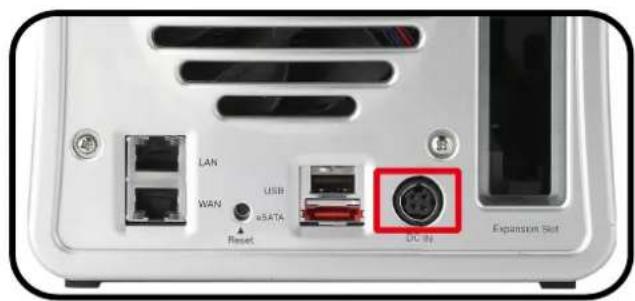
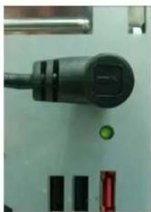
Close-up of a network device rear panel showing ports, connectors, and a cable (no visible text or symbols)- Connect the provided power cord into the universal power socket on the back panel. Plug the other end of the cord into a surge protected socket. Press the power supply switch to turn on the power supply.
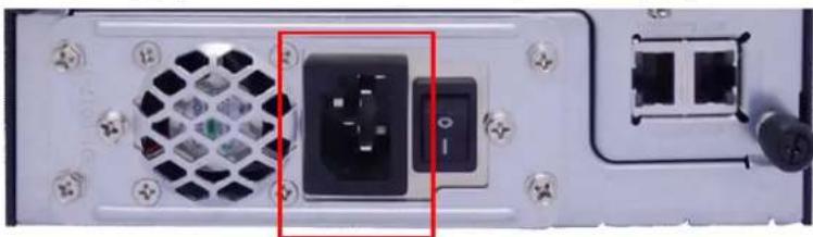
natural_image
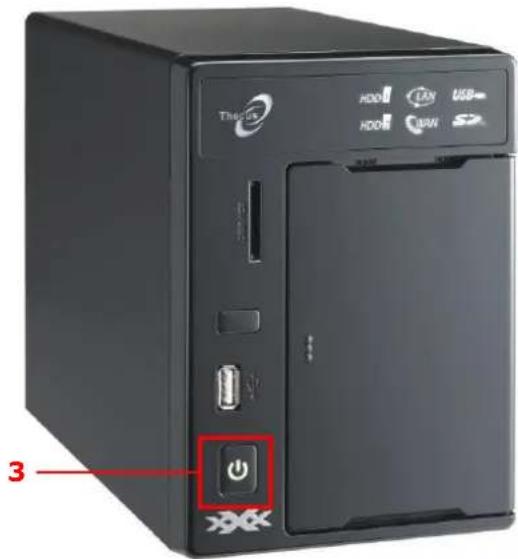
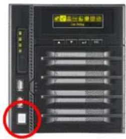
Back view of a computer power supply unit showing a black socket and connector (no text or symbols visible)- Press the power button on the front panel to boot up the N5200XXX/N5500.
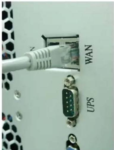
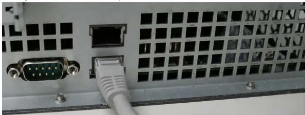
To connect the 1U4200XXX/1U4600 to your network, follow the steps below:
- Connect an Ethernet cable from your network to the WAN/LAN1 port on the back panel of the 1U4200XXX/1U4600.
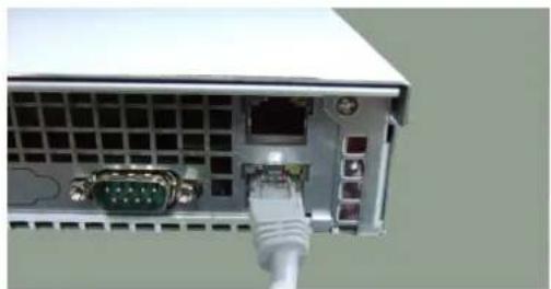
natural_image
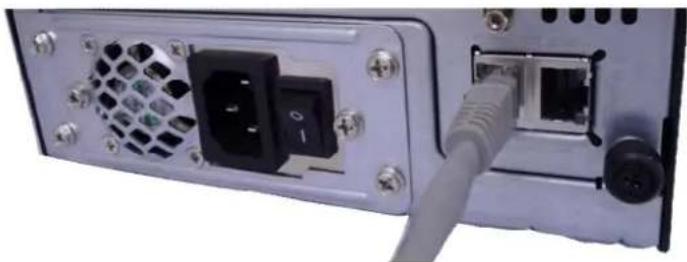
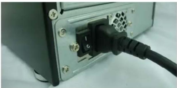
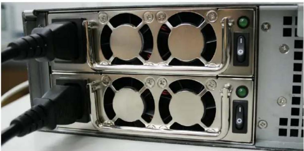
Close-up of a server rack with VGA port, RJ8 connector, and network ports (no visible text or symbols)- Connect the provided power cord into the universal power socket on the back panel. Plug the other end of the cord into a surge protected socket. Press the power supply switch to turn on the power supply.
NOTE
If you are installing the 1U4200XXXR/1U4600R, be sure to connect both power cables. If you do not, the system will assume one power supply has failed, and an alarm will sound.
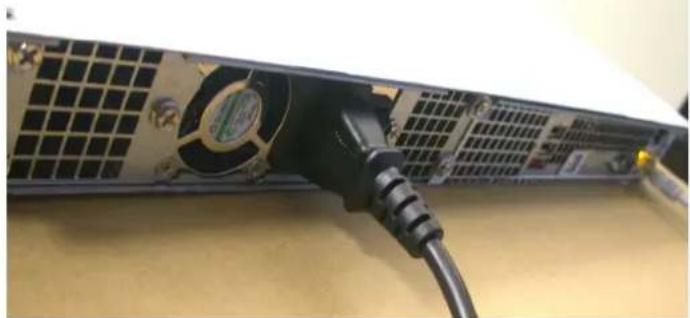
natural_image
Close-up of a black cable plugged into a server rack with ventilation grilles (no visible text or symbols)- Press the power button on the front panel to boot up the 1U4200XXX/1U4600.
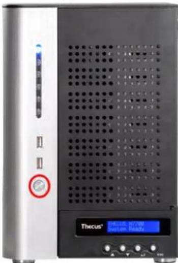
To connect N7700 series NAS to your network, follow the steps below:
- Connect an Ethernet cable from your network to the WAN/LAN1 port on the back panel of the N7700.
- Connect the provided power cord into the universal power socket on the back panel. Plug the other end of the cord into a surge protected socket. Press the power supply switch to turn on the power supply.
natural_image
Close-up of a black cable inserted into a device with an internal connector (no visible text or symbols)- Press the power button on the Front Panel to boot up the N7700.
natural_image
Front view of a Thicus 10788 server rack with indicator lights and control buttons (no readable text beyond branding)To connect N8200XXX/N8800 series NAS to your network, follow the steps below:
- Connect an Ethernet cable from your network to the WAN/LAN1 port on the back panel of the N8200XXX/N8800.
natural_image
Close-up of a server rack with VGA connectors and a white USB cable (no visible text or symbols)- Connect the provided power cord into the universal power socket on the back panel. Plug the other end of the cord into a surge protected socket. Press the power supply switch to turn on the power supply.
natural_image
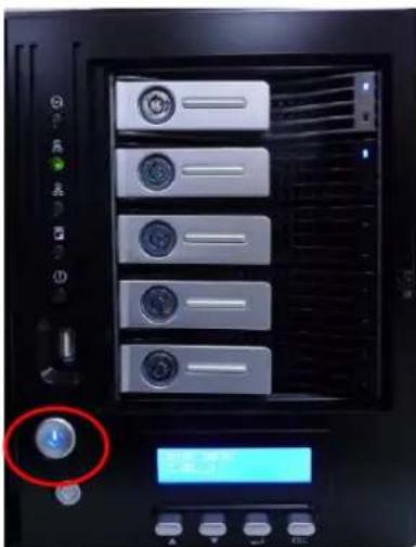
Close-up of a server rack with multiple fans and connected cables (no visible text or symbols)- Press the power button on the front panel to boot up the N8200XXX/N8800.
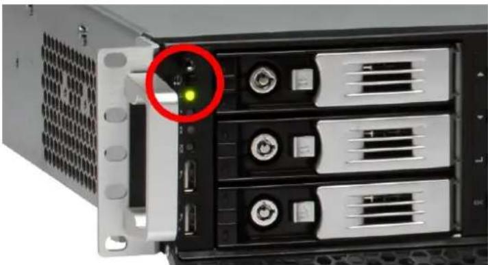
natural_image
Front view of a server rack with a highlighted drive (no visible text or labels)Chapter 3: First Time Setup
Overview
Once the hardware is installed, physically connected to your network, and powered on, you can configure the Thecus IP storage so that it is accessible to your network users. There are two ways to set up your Thecus IP storage: using the Thecus Setup Wizard or the LCD display. Follow the steps below for initial software setup.
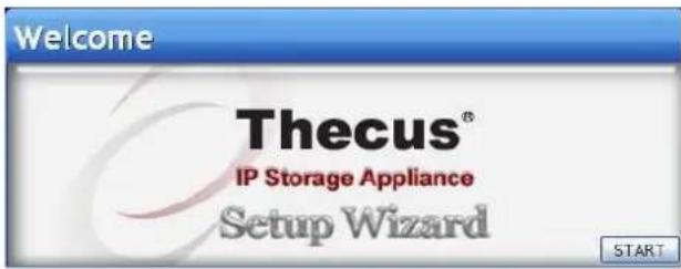
Thecus Setup Wizard
The handy Thecus Setup Wizard makes configuring Thecus IP storage a snap. To configure the Thecus IP storage using the Setup Wizard, perform the following steps:
- Insert the installation CD into your CD-ROM drive (the host PC must be connected to the network).
- The Setup Wizard should launch automatically. If not, please browse your CD-ROM drive and double click on Setup.exe.
NOTE
For MAC OS X users, double click on Thecus Setup Wizard .dmg file.
- The Setup Wizard will start and automatically detect all Thecus storage devices on your network. If none are found, please check your connection and refer to Chapter 7: Troubleshooting for assistance.
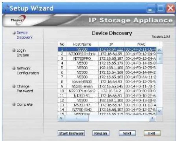
-
Select the Thecus IP storage that you like to configure.
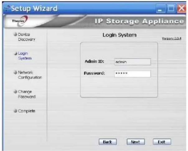
-
Login with the administrator account and password. The default account and password are both "admin".
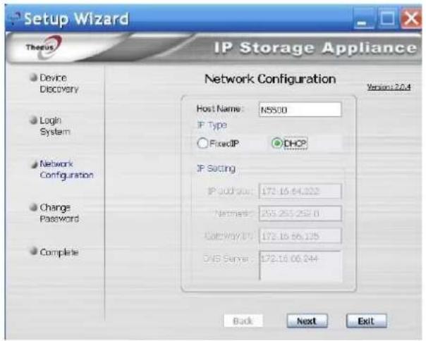
- Name your Thecus IP storage and configure the network IP address. If your switch or router is configured as a DHCP Server, configuring the Thecus IP storage to automatically obtain an IP address is recommended. You may also use a static IP address and enter the DNS Server address manually.
- Change the default administrator password.
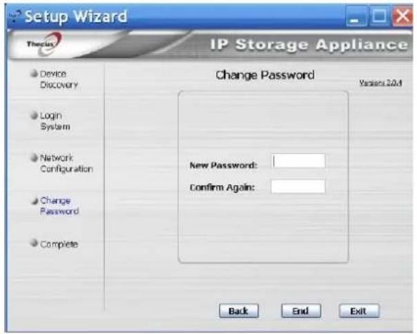
- Finished! Access the Thecus IP storage Web Administrator Interface by pressing the Start Browser button. You can also configure another Thecus IP storage at this point by clicking the Setup Other Device button. Press Exit to exit the wizard.
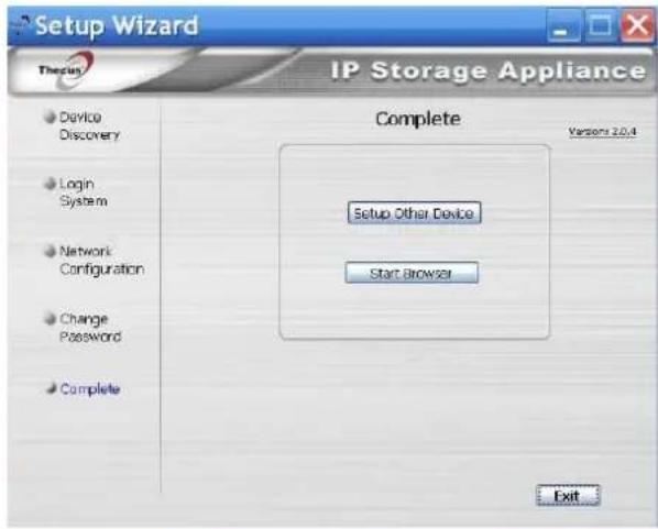
NOTE
The Thecus Setup Wizard is designed for installation on systems running Windows XP/2000/vista/7 or Mac OSX or later. Users with other operating systems will need to install the Thecus Setup Wizard on a host machine with one of these operating systems before using the unit.
LCD Operation (N5200XXX/N5500/1U4200XXX/1U4600/N7700 series/N8200XXX/N8800 series)
The mentioned models above are equipped with an LCD on the front for easy status display and setup. There are four buttons on the front panel to control the LCD functions.
LCD Controls
Use the Up (▲), Down (▼), Enter (↓) and Escape (ESC) keys to select various configuration settings and menu options for Thecus IP storage configuration.
The following table illustrates the keys on the front control panel:
LCD Controls
Icon Function Description
▲ Up Button Select the previous configuration settings option.
▼ Down Button USB copy confirmation display.
Enter Enter the selected menu option, sub-menu, or parameter setting.
ESC Escape Escape and return to the previous menu.
There are two modes of operation for the LCD: Display Mode and Management Mode.
Display Mode
During normal operation, the LCD will be in Display Mode.
| Display Mode |
| Item Description |
| Host Name Current host name of the system. |
| WAN/LAN1 Current WAN/LAN1 IP setting. |
| LAN2 Current LAN2 IP setting. |
| Link Aggregation Current Link Aggregation status |
| System Fan1 Current system fan1 status. |
| System Fan2 Current system fan2 status. |
| CPU Fan Current CPU fan status |
| 2009/05/22 12:00 Current system time. |
| Disk Info Current status of disk slot has been installed |
| RAID Current RAID status. |
The Thecus IP storage will rotate these messages every one-two seconds on the LCD display.
USB Copy
The USB Copy function enables you to copy files stored on USB devices such as USB disks and digital cameras to the Thecus IP storage by press button. To use USB copy, follow the steps below:
-
Plug your USB device into an available USB port on the Front end.
-
In Display Mode, press the Down Button (▼).
-
The LCD will display "USB Copy?"
-
Press Enter (↓) and the Thecus IP storage will start copying USB disks connected to the front USB port.
-
All of data will be copied into system folder named "USB copy".
Management Mode
During setup and configuration, the LCD will be in Management Mode.
To enter into Management Mode, press Enter (←) and an "Enter Password" prompt will show on the LCD.
At this time, the administrator has to enter the correct LCD password. System will check whether the correct LCD password has been entered. The default LCD password is "0000". If correct password is entered, you will enter into the Management Mode menu.
| Management Mode | |
| Item | Description |
| WAN/LAN1 Setting | IP address and netmask of your WAN/LAN1 ports. |
| LAN2 Setting | IP address and netmask of your LAN2 ports. |
| Link Agg. Setting | Select Load Balance, 802.3ad or Failover. |
| Change Admin Passwd | Change administrator's password for LCD operation. |
| Reset to Default | Reset system to factory defaults. |
| Exit | Exit Management Mode and return to Display Mode. |
NOTE
You can also change your LCD password using the Web Administration Interface by navigating to System Management > Administrator Password. For more on the Web Administration Interface, see Chapter 4: System Management.
LCD Operation (N3200XXX/N0503)
LCD Controls
Use the Down (▼), Up (▲), Enter (←) and Escape (ESC) keys to operate LCD to view system information and USB copy.
The following table illustrates the keys on the front control panel:
LCD Controls
Icon Function Description
▼ Down Button Select the previous configuration settings option.
▲ Up Button Select the next configuration settings option.
← Enter Enter to display USB copy operation.
ESC Escape Escape to give up USB copy.
Press and hold for 3 seconds to turn off the LCD's backlight. Press any button to switch the backlight back on.
Display Mode
During normal operation, the LCD will be in Display Mode.
| Display Mode | |
| Item Description | |
| Host Name Current host name of the system. | |
| WAN/LAN1 Current WAN/LAN1 IP setting. | |
| LAN2 Current LAN2 IP setting. | |
| RAID Current RAID status. | |
| System Fan | Current system fan status. |
| Temperature Current system temperature. | |
| Date/Time | Current system date and time |
| Up Time | The system power on time since last start |
The N0503 will rotate these messages every three seconds on the LCD display.
NOTE
If the RAID array is in a degraded state, the LCD display will be stopped in display mode and show which disk is degraded in the array: RAID: Degraded [Disk 1]
USB Copy
The USB Copy function enables you to copy files stored on USB devices such as USB disks and digital cameras to the N3200XXX/N0503 with a press of a button. To use USB copy, follow the steps below:
-
Plug your USB device into an available USB port on the Front Panel.
-
In Display Mode, press the Enter ( ).
-
The LCD will display "USB Copy?"
-
Press Enter (J) and the N3200XXX/N0503 will start copying USB disks connected to the front USB port. The LCD will display the USB copy progress and results.
OLED Operation (N4200 series)
OLED Operation
The N4200 series is equipped with an OLED on the front for easy status display and setup. There are four buttons on the front panel to control the OLED functions.
OLED Controls
Use the Up (▲), Down (▼), Enter (↓) and Escape (ESC) keys to select various configuration settings and menu options for N4200series configuration.
The following table illustrates the keys on the front control panel:
OLED Controls
Icon Function Description
▲ Up Button Select the previous configuration settings option.
▼ Down Button USB copy confirmation display.
← Enter Enter the selected menu option, sub-menu, or parameter setting.
ESC Escape Escape and return to the previous menu.
There are two modes of operation for the OLED: Display Mode and Management Mode.
Display Mode
During normal operation, the OLED will be in Display Mode.
| Display Mode | |
| Item Description | |
| Host Name Current host name of the system. | |
| WAN/LAN1 Current WAN/LAN1 IP setting. | |
| LAN2 Current LAN2 IP setting. | |
| Link Aggregation | Current Link Aggregation status |
| System Fan | Current system fan status. |
| CPU Fan | Current CPU fan status |
| 2009/05/22 12:00 | Current system time. |
| RAID | Current RAID status. |
The N4200 series will rotate these messages every one-two seconds on the OLED display.
Typical Setup Procedure
From the Web Administration Interface, you can begin to setup your Thecus IP storage for use on your network. Setting up the Thecus IP storage typically follows the five steps outlined below.
For more on how to use the Web Administration Interface, see
Chapter 4: Web Administration Interface.
Step 1: Network Setup
From the Web Administration Interface, you can configure the network settings of the Thecus IP storage for your network. You can access the Network menu from the menu bar.
For details on how to configure your network settings, refer to
Chapter 4: System Network.
Step 2: RAID Creation
Next, administrators can configure their preferred RAID setting and build their RAID volume. You can access RAID settings from the menu bar of the Web Administration Interface by navigating to Storage Management > RAID Configuration.
For more information on configuring RAID, see
Chapter 4: System Management > RAID Configuration.
Don't know which RAID level to use? Find out more about the different RAID levels from Appendix B: RAID Basics.
Step 3: Create Local Users or Setup Authentication
Once the RAID is ready, you can begin to create local users for Thecus IP storage, or choose to setup authentication protocols such as Active Directory (AD).
For more on managing users, go to Chapter 4:User and Group Authentication.
For more information on configuring Active Directory, see
Chapter 4: User and Group Authentication > ADS/NT Support.
For information about the benefits of Active Directory, see Appendix C: Active Directory Basics.
Step 4: Create Folders and Set Up ACLs
Once users are introduced into your network, you can begin to create various folders on the Thecus IP storage and control user access to each using Folder Access Control Lists.
More information on managing folders, see
Chapter 4: Storage Management> Share Folder.
To find out about configuring Folder Access Control Lists, see Chapter 4: Storage
Management > Share Folder> Folder Access Control List (ACL).
Step 5: Start Services
Finally, you can start to setup the different services of Thecus IP storage for the users on your network. You can find out more about each of these services by clicking below:
SMB/CIFS
Apple File Protocol (AFP)
Network File System (NFS)
File Transfer Protocol (FTP)
iTunes Server
Printer Server
Photo Server
Chapter 4: System Administration
Overview
The Thecus IP storage provides an easily accessible Web Administration Interface. With it, you can configure and monitor the Thecus IP storage anywhere on the network.
Web Administration Interface
Make sure your network is connected to the Internet. To access Thecus IP storage Web Administration Interface:
- Type the Thecus IP storage IP address into your browser. (Default IP address is http://192.168.1.100)
NOTE
Your computer's network IP address must be on the same subnet as the Thecus IP storage. If the Thecus IP storage has default IP address of 192.168.1.100, your managing PC IP address must be 192.168.1.x, where x is a number between 1 and 254, but not 100.
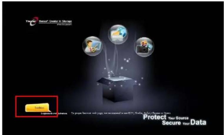
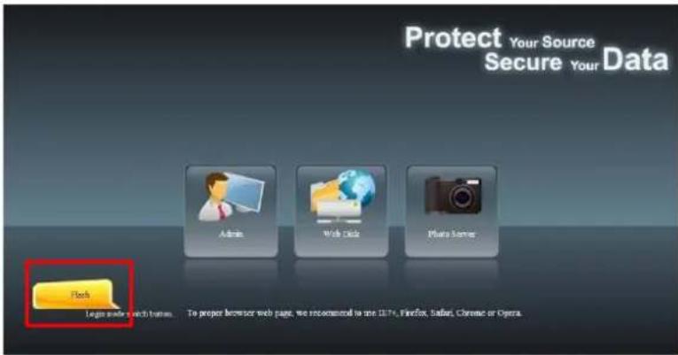
NOTE
This page can be displayed with Flash or with HTML. Choose Flash for Flash (shown in the top figure) and Traditional for HTML (shown in the bottom figure).
- Login to the system using the administrator user name and password. The factory defaults are:
User Name: admin
Password: admin
※ If you changed your password in the setup wizard, use the new password.
Once you are logged in as an administrator disclaimer page will appear as below. Please click the check box if you do not want to have this page displayed during the next login.
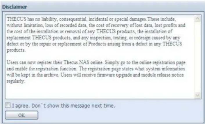
Following by disclaim page, you will see the Web Administration Interface. From here, you can configure and monitor virtually every aspect of the Thecus IP storage from anywhere on the network.
My Favorite
The user interface with "My Favorite" shortcut is allowed user to designate often used items and have them display on the main screen area. The figure below displays 12 default favorite functions.
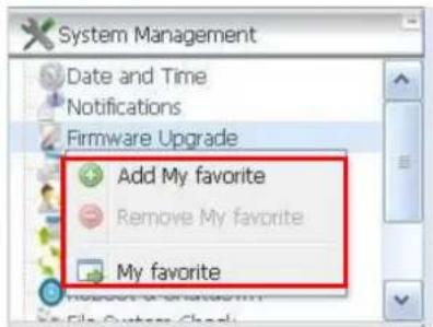
Administrators can add or remove favorite functions to My Favorites by right clicking the mouse on the menu tree.
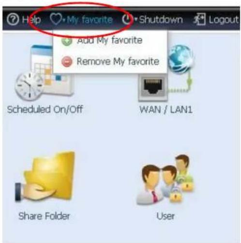
The other way administrators can add favorite functions is by clicking the "Add Favorite" icon in each function screen. Please refer figure below in red circuit icon.
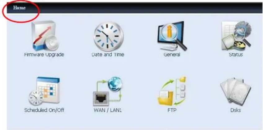
To return to the favorite screen, simply click "Home" located at the left hand corner of the main screen.
Menu Bar
The Menu Bar is where you will find all of the information screens and system settings of Thecus IP storage. The various settings are placed in the following groups on the menu bar:
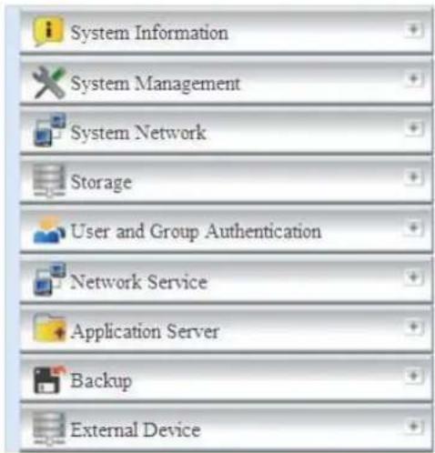
| Menu Bar | |
| Item Description | |
| System Information Current system status of the Thecus IP storage. | |
| System Management Various Thecus IP storage system settings and information. | |
| System Network Information and settings for network connections, as well as various services of the Thecus IP storage. | |
| Storage Information and settings for storage devices installed into the Thecus IP storage. | |
| User and Group Authentication | Allows configuration of users and groups. |
| Network Service Setup and manage protocols such as Samba/CIFS, AFP, NFS, FTP, and other network services. | |
| Application Server Printer Server and iTunes Server to set up of the Thecus IP storage. | |
| Backup Category of Backup Features set up of the Thecus IP storage. | |
| External Device | Thecus IP storage support printer serving and UPS backup power supplies. |
Moving your cursor over any of these items will display the dropdown menu selections for each group.
In the following sections, you will find detailed explanations of each function, and how to configure your Thecus IP storage.
Message Bar
You can get information about system status quickly by moving mouse over.
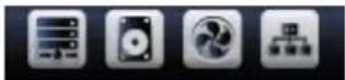
| Message Bar | ||
| Item Status Description | ||
| RAID Information. | Display the status of created RAID volume. Click to go to RAID information page as short cut. | |
| Disks Information. | Display the status of disks installed in the system. Click to go to Disk information page as short cut. | |
| FAN. | Display system FAN Status. Click to go to System Status page as short cut. | |
| Network. | Green: The system is connected to the Internet.Red:The system is unable to connect to the Internet. | |
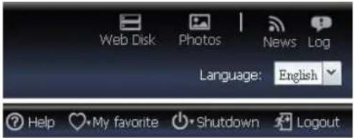
- Web Disk
Click this to log into the Web Disk.
- Photos
Click this to log into the photo server.
- News
Accesses online registration and the latest release news.
- Log
Accesses the system log. New logs will be displayed with an icon here.
• Language Selection
The Thecus IP storage supports multiple Languages, including:
English, Japanese, Traditional Chinese, Simplified Chinese, French, German, Italian, Korean, Spanish, Russia, Polish, Portugal
On the menu bar, click Language and the selection list appears. This user interface will switch to selected Language for Thecus IP storage.
• Help
Click this to toggle the help page open and browse or search through the UI help database. The current page's help section will be displayed first.
• My Favorite
Add/Remove the current page from the Home page.
- Shutdown
Choose Shutdown or Reboot from the dropdown menu to shutdown or reboot your NAS.
- Logout
Click to log out of Web Administration Interface.
System Information
Information provides viewing on current Product info, System Status, Service Status and Logs.
The menu bar allows you to see various aspects of the Thecus IP storage. From here, you can discover the status of the Thecus IP storage, and also other details.
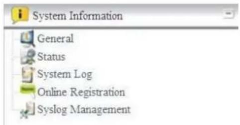
General Information
Once you login, you will first see the basic Product Information screen providing Manufacturer, Product No., Firmware Version, and System Up Time information.
| Manufacturer | Thecus |
| Product No. | N4200PRO |
| Firmware Version | 5.00.00.15 |
| Up Time | 3 hours 8 minutes |
| Product Information | |
| Item Description | |
| Manufacturer Displays the name of the system manufacturer. | |
| Product No. Shows the model number of the system. | |
| Firmware version Shows the current firmware version. | |
| Up time Displays the total run time of the system. | |
System/Service Status
From the Status menu, choose the System item, System Status and Service Status screens appear. These screens provide basic system and service status information.
| CPU Activity | 0% |
| CPU Fan Speed | OK |
| System Fan 1 Speed | OK |
| Up Time | 3 hours 10 minutes |
| AFP Status | Stopped |
| NFS Status | Stopped |
| SMB/CIFS Status | Running |
| FTP Status | Stopped |
| TFTP Status | Stopped |
| Nsync Status | Running |
| UPnP Status | Stopped |
| SNMP Status | Stopped |
| System Status | |
| Item Description | |
| CPU Loading (%) Displays current CPU workload of the Thecus IP storage. | |
| CPU Fan Speed Displays current CPU fan status. | |
| System Fan Speed Displays the current status of the system fan. | |
| Up Time Shows how long the system has been up and running. | |
| Service Status | |
| Item Description | |
| AFP Status The status of the Apple Filing Protocol server. | |
| NFS Status The status of the Network File Service Server. | |
| SMB/CIFS Status The status of the SMB/CIFS server. | |
| FTP Status The status of the FTP server. | |
| TFTP Status The status of the TFTP server. | |
| Nsync Status The status of the Nsync server. | |
| UPnP Status The status of the UPnP service. | |
| SNMP | The status of the SNMP service. |
Logs
From the System Information menu, choose the Logs item and the System Logs screen appears. This screen shows a history of system usage and important events such as disk status, network information, and system booting. See the following table for a detailed description of each item:
![System Log All Info Warnings Errors Download All Log Files Truncate All Log Files Number of lines per page 13 Time Details Help 2010/12/22 12:17:49 N4200PRO-PM : User admin logged in from 172.16.64.153 2010/12/22 09:44:54 N4200PRO-PM : The system N4200PRO-PM RAID is healthy now. 2010/12/22 09:44:52 N4200PRO-PM : Syslog service stop. 2010/12/22 09:44:52 N4200PRO-PM : N4200PRO-PM boot 2010/12/22 09:44:49 N4200PRO-PM : mdadm:/dev/md1 has been started with 3 drives. 2010/12/22 09:44:49 N4200PRO-PM : [Disk sdc] UUID[raidS:d8414dbc:5734bdcc:270dc66ffe2b4200;Thu Oct 28 18:16:56 2... 2010/12/22 09:44:49 N4200PRO-PM : [Disk sdb] UUID[raidS:d8414dbc:5734bdcc:270dc66ffe2b4200;Thu Oct 28 18:16:56 2... 2010/12/22 09:44:49 N4200PRO-PM : [Disk sda] UUID[raidS:d8414dbc:5734bdcc:270dc66ffe2b4200;Thu Oct 28 18:16:56 2... 2010/12/22 09:44:49 N4200PRO-PM : Syslog service stop. 2010/12/22 09:44:49 N4200PRO-PM : Assemble RAID [md1] from [/dev/sda2 /dev/sdb2 /dev/sdc2] 2010/12/22 09:44:19 thecns : DataBase[/app/cfg/wireless.db] Check Ok 2010/12/22 09:44:19 thecns : DataBase[/app/cfg/stackable.db] Check Ok 2010/12/22 09:44:19 thecns : DataBase[/app/cfg/shortcut db] Check Ok Page 1 of 19 Displaying logs 1 - 13 of 24 Time Logs Information Sort Ascending n logged in from 172.16.65.107 Sort Descending m n5500-dual01 found UPS is unavailable. Columns Time unavailable. 5500-dual01 : The syst Logs Information 5500-dual01 : The system n5500-dual01 found UPS is unavailable. 5500-dual01 : The system n5500-dual01 found UPS is unavailable. 5500-dual01 : User admin logged in from 172.16.65.107 5500-dual01 : The system n5500-dual01 found UPS is unavailable.](/content/2026/06/1184879/images/c079364177d2a4eb56d7fd950f721da97c3d3fb3c11a92e4308d5b3e2c1f26d3.jpg)
See the following table for a detailed description of each item:
| System Logs | |
| Item Description | |
| All Provides all log information including system messages, warning messages and error messages. | |
| INFO Records information about system messages. | |
| WARN Shows only warning messages. | |
| ERROR Shows only error messages. | |
| Download All Log File Export all logs to an external file. | |
| Truncate All Log File Clear all log files. | |
| The number of lines per page □ | Specify desired number of lines to display per page. |
| Sort Ascending Shows logs by date in ascending order. | |
| Sort Descending Shows logs by date in descending order. | |
| |<< < > >>| | Use the forward ( > >>| ) and backward ( |<< < ) buttons to browse the log pages. |
| Re-loading logs. | |
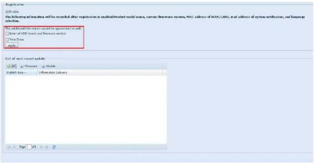
On-line Register
From the System Information menu, choose the On-line Register item and the System On-line Register screen appears. The on-line register service can periodically update the user when new firmware and software modules are released by Thecus. To enable this service, simply check the "Enable" check box. By enabling this service, the items in bold will be sent to Thecus via the Internet.
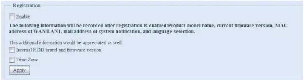
Other than the defined items sent upon registration, there are also two additional items: "HDD Info" and "Time Zone". These two optional items can also be sent to Thecus anonymously for analysis and statistics purposes. To send these items, simply check the desired checkboxes to help Thecus improve its products and services.
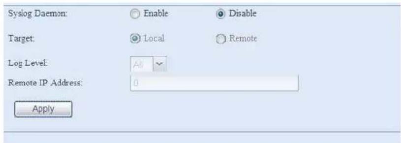
Syslog Management
Generates system log messages for the syslog server.
These messages are stored on your NAS in: Nsync > log> messages.
Information can be obtained in two ways: locally and remotely.
Local Access - When Local is selected, log messages can be viewed directly through samba. However, to access the Nsync folder through samba, the folder must be set as browseable and the user must be given ACL permissions. In OS X, UNIX extensions must be disabled under Network Service > Samba/CIFS in the UI.
Remote Access - They can also be viewed remotely by selecting Remote and inputting a Remote IP Address into the input field. This will allow a TFTP program, such as TFTPd32, to access the system log remotely from a computer.
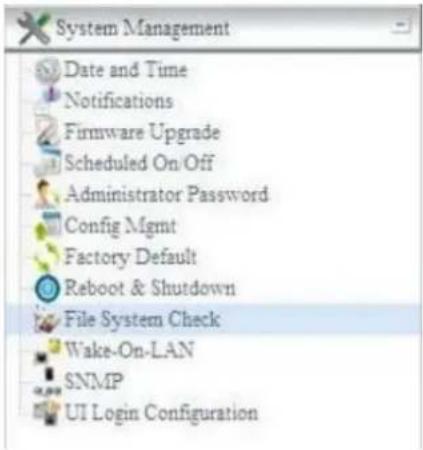
System Management
The System Management menu gives you a wealth of settings that you can use to configure your Thecus IP storage system administration functions. You can set up system time, system notifications, and even upgrade firmware from this menu.
Date and Time: System Date and settings
From the Date and time menu, choose the item and the screen appears. Set the desired Date, Time, and Time Zone. You can also elect to synchronize the system time on Thecus IP storage with an NTP (Network Time Protocol) Server.
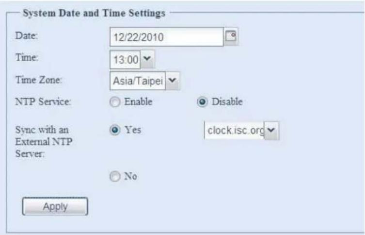
See the following table for a detailed description of each item:
| Time | |
| Item Description | |
| Date Sets the system date. | |
| Time Sets the system time. | |
| Time Zone Sets the system time zone. | |
| NTP Server | Select Enable to synchronize with the NTP server.Select Disable to close the NTP server synchronization. |
| Sync with external NTP Server | Select YES to allow Thecus IP storage to synchronize with an NTP server of your choice. Press Apply to change. |
WARNING
If an NTP server is selected, please make sure your Thecus IP storage has been setup to access the NTP server.
Notification configuration
From the menu, choose the Notification item, and the Notification
Configuration screen appears. This screen lets you have Thecus IP storage notify you in case of any system malfunction. Press Apply to confirm all settings. See following table for a detailed description of each item.
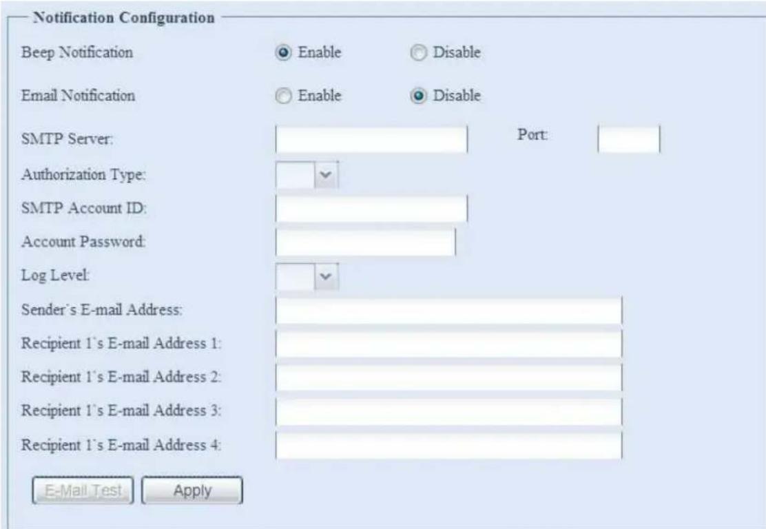
| Notification Configuration | |
| Item Description | |
| Beep Notification Enable | or disable the system beeper that beeps when a problem occurs. |
| Email Notification Enable | or disable email notifications of system problems. |
| SMTP Server Specifies | the hostname/IP address of the SMTP server. |
| Port Specifies the port | to send outgoing notification emails. |
| Auth Type Select the SM | MTP Server account authentication type. |
| SMTP Account ID Set the | the SMTP Server Email account ID. |
| Account Password Enter | a new password. |
| E-mail From Set email | address to send email. |
| Receiver's E-mail Address (1,2,3,4) | Add one or more recipient's email addresses to receive email notifications. |
NOTE
Consult with your mail server administrator for email server information.
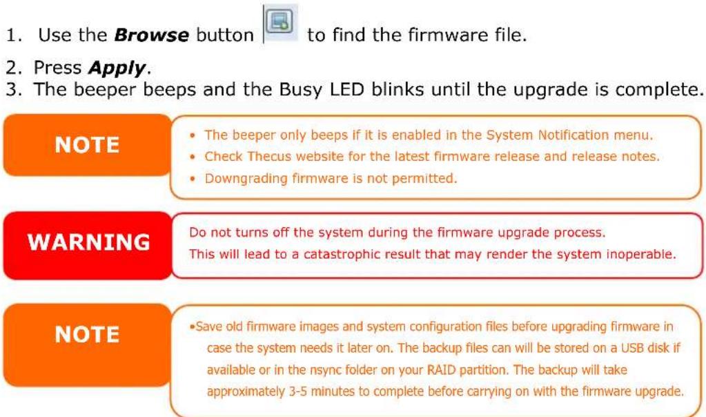
Firmware Upgrade
From the menu, choose the Firmware Upgrade item and the Firmware Upgrade screen appears.
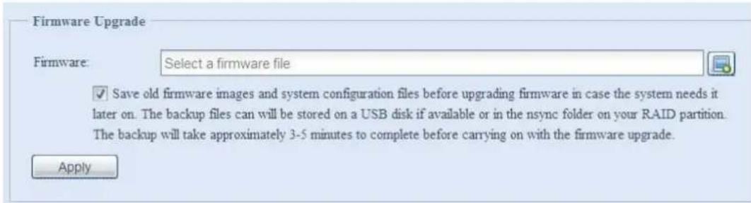
Follow the steps below to upgrade your firmware:
Schedule Power On/Off
Using the Thecus IP storage System Management, you can save energy and money by scheduling the Thecus IP storage to turn itself on and off during certain times of the day.
From the menu, choose the Schedule Power On/Off item and the Schedule Power On/Off screen appears.
To designate a schedule for the Thecus IP storage to turn on and off, first enable the feature by checking the Enable Schedule Power On/Off checkbox.
Then, simply choose an on and off time for each day of the week that you would like to designate a schedule by using the various dropdowns.
Finally, click Apply to save your changes.
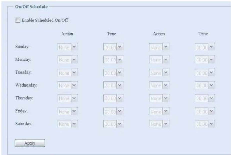
Example - Monday: On: 8:00; Off: 16:00
System will turn on at 8:00 AM on Monday, and off at 16:00 on Monday. System will turn on for the rest of the week.
If you choose an on time, but do not assign an off time, the system will turn on and remain on until a scheduled off time is reached, or if the unit is shutdown manually.
Example - Monday: On: 8:00
System will turn on at 8:00 AM on Monday, and will not shut down unless powered down manually.
You may also choose two on times or two off times on a particular day, and the system will act accordingly.
Example - Monday: Off: 8:00; Off: 16:00
System will turn off at 8:00 AM on Monday. System will turn off at 16:00 PM on Monday, if it was on. If the system was already off at 16:00 PM on Monday, system will stay off.
Administrator password
From the menu, choose the Administrator Password item and the Change Administrator Password screen appears. Enter a new password in the New Password box and confirm your new password in the Confirm Password box. Press Apply to confirm password changes.
There is also password for enter LCD setting you could setup here. Enter a new password in the New Password box and confirm your new password in the Confirm Password box. Press Apply to confirm password changes.
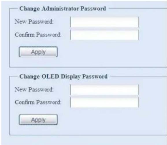
See the following table for a detailed description of each item.
| Change Administrator and LCD Entry Password | |
| Item Description | |
| New Password Type in a new administrator password. | |
| Confirm Password Type the new password again to confirm. | |
| Apply Press this to save your changes. |
Config Mgmt
From the menu, choose the Config Mgmt item and the System Configuration Download/Upload screen appears. From here, you can download or upload stored system configurations.
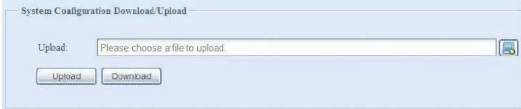
See the following table for a detailed description of each item.
| System Configuration Download/Upload | |
| Item Description | |
| Download Save and export the current system configuration. | |
| Upload Import a saved configuration file to overwrite current system configuration. |
Factory default
From the menu, choose the Factory Default item and the Reset to Factory Default screen appears. Press Apply to reset Thecus IP storage to factory default settings.

WARNING
Resetting to factory defaults will not erase the data stored in the hard disks, but WILL revert all the settings to the factory default values.
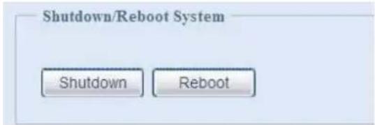
Reboot & Shutdown
From the menu, choose Reboot & Shutdown item, and the Shutdown/Reboot System screen appears. Press Reboot to restart the system or Shutdown to turn the system off.
File System check
The File System Check allows you to perform a check on the integrity of your disks' file system. Under the menu, click File system Check and the File System Check prompt appears.
![File System Check The file system has been checked successfully. Reboot the system make the changes effective. ZFS file systems don't need file system checks! Encrypted RAID does not support file system checks! Press [ Apply ] to reboot the system now. Apply](/content/2026/06/1184879/images/b20403eb9647742da72b0063a5ceaa3d2e4e376e809526c1c0440cb6f271a062.jpg)
To perform a file system check, click Apply.
Once clicked, the following prompt will appear:
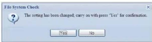
Click Yes to reboot the system.
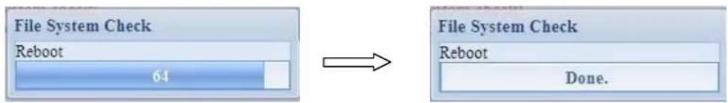
flowchart
graph LR
    A["File System Check\nReboot\n64"] --> B["File System Check\nReboot\nDone."]
Once the system has rebooted, you will be returned to the File System Check prompt. There you will see the available RAID volumes to run the file system check on except ZFS volume, ZFS has no need to perform file system check. Check the desired RAID volumes and click Next to proceed with the file system check. Click Reboot to reboot without running the check.
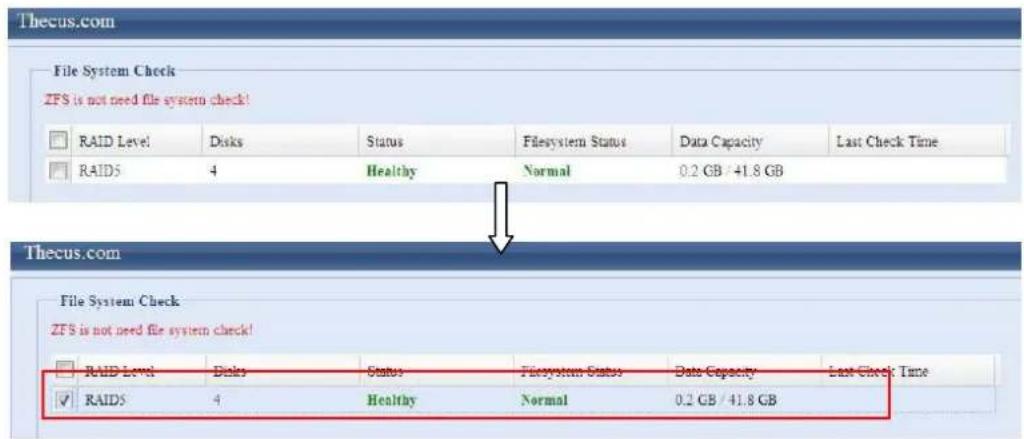
Once you click Next, you will see the following screen:
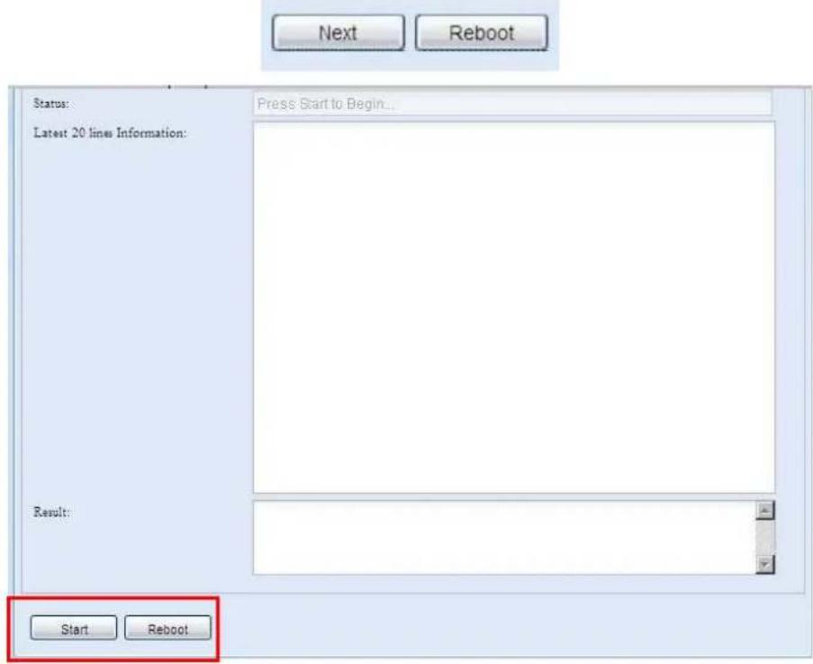
Click Start to begin the file system check. Click Reboot to reboot the system. When the file system check is run, the system will show 20 lines of information until it is complete. Once complete, the results will be shown at the bottom.
![[2009/6/8 14:5:33] 4 8 8 [2009/6/8 14:5:33] Pass 6: Checking group summary information [2009/6/8 14:5:33] 5 0 16 [2009/6/8 14:5:33] 5 1 16 [2009/6/8 14:5:33] 5 2 16 [2009/6/8 14:5:33] 5 3 16 [2009/6/8 14:5:33] 5 4 16 [2009/6/8 14:5:33] 5 5 16 [2009/6/8 14:5:33] 5 6 16 [2009/6/8 14:5:33] 5 7 16 [2009/6/8 14:5:33] 5 8 16 [2009/6/8 14:5:33] 5 9 16 [2009/6/8 14:5:33] 5 10 16 [2009/6/8 14:5:33] 5 11 16 [2009/6/8 14:5:33] 5 12 16 [2009/6/8 14:5:33] 5 13 16 [2009/6/8 14:5:33] 5 14 16 [2009/6/8 14:5:33] 5 15 16 [2009/6/8 14:5:33] 5 16 16 [2009/6/8 14:5:33] /dev/vg0/syslv: 33/262144 filtec (3.0% non-contiguous), 16763/262144 blocks Result: RAID [1,2,3,4,5 ] System Volume : Exit Code = 0 , No errors. RAID [1,2,3,4,5 ] Data Volume : Exit Code = 0 , No errors. Start Reboot](/content/2026/06/1184879/images/19b183ec47f8ab6464794a627604617f14ee9c1154dc496f61439cf763dfac7a.jpg)
NOTE
The system must be rebooted before Thecus IP storage can function normally after file system check complete.
Wake-Up On LAN (WOL)
The Thecus IP storage has the ability to be awoken from sleep mode via WAN/LAN1 port.
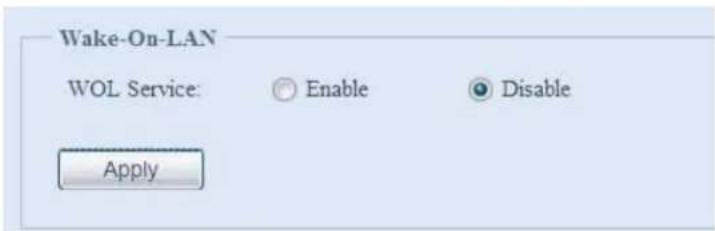
From the menu, choose the WOL item, and the Wake-up On LAN screen appears. From here, you can Enable or Disable.
| Wake-up On LAN Configuration | |
| Item Description | |
| WOL Service | Enable or Disable WOL service |
| Apply Click Apply to save changes. | |
SNMP Support
From the menu, choose the SNMP item and the SNMP Support screen appears. You could enable the SNMP function and filled in the related information in each fields. With the SNMP management software could get system basic information.
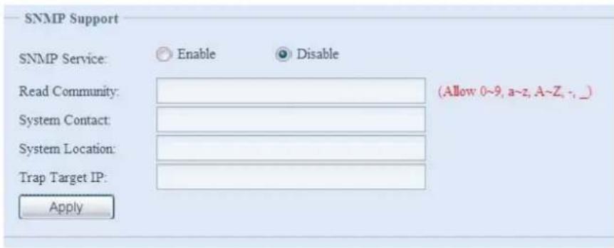
From the menu, choose the SNMP item, and the SNMP Support screen appears. From here, you can Enable or Disable.
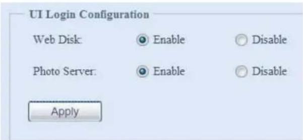
UI Login Configuration
Adjusts UI Login Configuration settings. You can enable/disable the Web Disk and Photo Server functions, according to your needs.
For the 3X series, users need to install the photo server module or web disk module to access these functions.
System Network
Use the System Network menu to make network configuration settings as well as service support settings.
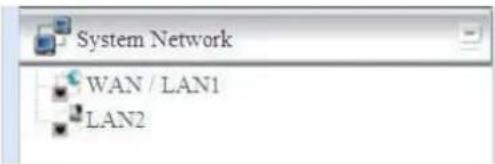
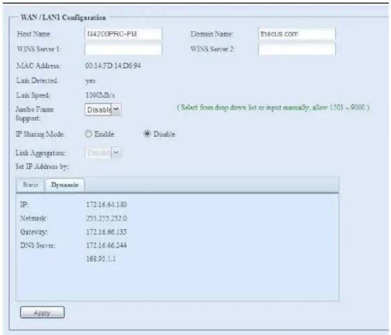
WAN/LAN1
WAN/LAN1 Configuration
From the System Network menu, choose WAN/LAN1, and the WAN/LAN1 Configuration screen appears. This screen displays the network parameters of the WAN/LAN1 connection. You may change any of these items and press Apply to confirm your settings. See a description of each item in the following table:
| WAN/LAN1 Configuration | |
| Item Description | |
| Host name Host name that identifies the Thecus IP storage on the network. | |
| Domain name Specifies the domain name of Thecus IP storage. | |
| WINS Server To set a server name for NetBIOS computer. | |
| MAC Address MAC address of the network interface. | |
| Jumbo Frame Support Enable or disable Jumbo Frame Support of the WAN/LAN1 interface on your Thecus IP storage. | |
| IP Sharing Mode When enabled, PCs connected to the LAN2 port will be able to access the WAN/LAN1. | |
| Link Aggregation Specifies whether WAN/LAN1 and LAN2 ports will be aggregated and act as one port. There are 6 modes can be choose from:Load Balance/Fail-over/Balance-XOR/802.3ad/Balance-TLB/Balance-ALB | |
| Set IP Address by:Static / Dynamic | You can choose a static IP or Dynamic IP, and input your network configuration |
| IP IP address of the WAN/LAN1 interface. | |
| Netmask Network mask, which is generally: 255.255.255.0 | |
| Gateway | Default Gateway IP address. |
| DNS Server | Domain Name Service (DNS) server IP address. |
NOTE
- Only use Jumbo Frame settings when operating in a Gigabit environment where all other clients have Jumbo Frame Setting enabled.
- Enabling DHCP automatically turns on UPnP—see the Service Support Screen.
- If you are only using the WAN/LAN1 port, we suggest that you disable IP Sharing Mode. This will result in higher throughput.
- A correct DNS setting is vital to networks services, such as SMTP and NTP.
- To use the Link Aggregation with "802.3ad selected" feature, please make sure the networking equipment on the other end of Ethernet cable also supports 802.3ad protocol.
WARNING
Most Fast Ethernet (10/100) Switches/Routers do not support Jumbo Frame and you will not be able to connect to your Thecus IP Storage after Jumbo Frame is turned on. If this happens, turn off the Thecus IP Storage. Then, insert USB disk with factory reset utility included and power on the Thecus IP Storage. Till the system power on complete then it will bring your system settings back to factory default.
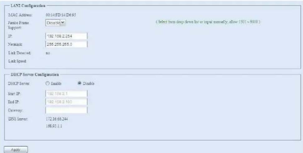
LAN2
LAN2 Configuration
The Thecus IP storage supports two Gigabit Ethernet ports for higher service availability. To configure these ports, choose LAN2 from the System Network menu, and the LAN2 Configuration screen appears. Press Apply to save your changes.
| LAN2 Configuration | |
| Item Description | |
| MAC Address Displays the MAC address of the LAN2 interface. | |
| Jumbo Frame Support | Enable or disable Jumbo Frame Support on the LAN2 interface. |
| IP Specifies the IP address of the LAN2 interface. | |
| Netmask Specifies the Network Mask of the LAN2 interface. | |
| Gateway When Thecus NAS as a DHCP server from LAN2, it can have another route to balance traffic bandwidth for its DHCP clients | |
| Link Detected Specifies the LAN2 port link status | |
| Lick Speed Specifies the LAN2 port link speed | |
NOTE
Before enabling Jumbo Frame Support, please make sure your network equipment supports Jumbo Frame. If your equipment is incompatible, you might not be able to connect to your Thecus IP storage.
NOTE
If the IP sharing mode setting is set to "Enable" under WAN/LAN21 port, then this 2^rd gateway cannot be configured.
DHCP Server Configuration
A DHCP server can be configured to assign IP addresses to devices connected to the LAN2 port. To configure these ports, choose LAN2 from the System Network menu.
| DHCP Configuration | |
| Item Description | |
| DHCP Server Enable or | disable the DHCP server to automatically assign IP address to PCs connected to the LAN2 interface. |
| Start IP Specifies the starting IP address of the DHCP range. | |
| End IP Specifies the ending IP address of the DHCP range. | |
| DNS Server Displayed | the DNS server IP address. |
NOTE
The IP Segment of WAN/LAN1 and LAN2 should not overlap.
WARNING
The IP address of the LAN2 interface should not be in the range of the Start IP address and End IP address.
Storage Management
The Storage menu displays the status of storage devices installed in the Thecus IP storage, and includes storage configuration options such as RAID and disk settings, folder configuration, space allocation and ISO Mount.
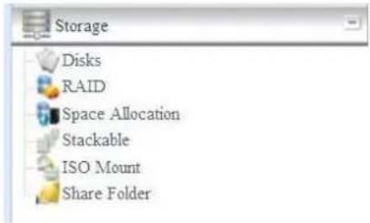
Disks Information
From the Storage menu, choose the Disks item and the Disks Information screen appears. From here, you can see various items about installed SATA hard disks. Blank lines indicate that a SATA hard disk is not currently installed in that particular disk slot.
NOTE
- The screen shot below just example from Thecus IP Storage. The disk slots can from 4 to 8 depend on the model of Thecus IP storage.
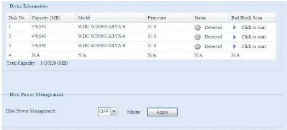
| Disks Information | |
| Item Description | |
| Disk No. Indicates disk location. | |
| Capacity Shows the SATA hard disk capacity. | |
| Model Displays the SATA hard disk model name. | |
| Firmware Shows the SATA hard disk firmware version. | |
| Status | Indicates the status of the disk. Can read OK, Warning, or Failed. |
| Bad Block scan Yes to start scan Bad Block. | |
| Total Capacity Shows the total SATA hard disk capacity. | |
| Disk Power Management | The administrator can set the disk to power down after a period of inactivity. |
NOTE
When the Status shows Warning, it usually means there are bad sectors on the hard disk. It is shown only as a precaution and you should consider changing the drives.
S.M.A.R.T. Information
On the Disks Information screen, the status of each disk will be displayed in the Status column. Clicking on an OK or Warning link will display the S.M.A.R.T Information window for that particular disk.
You may also perform disk SMART test, simply to click "Test" to start with. The result is only for reference and system will not take any action from its result.
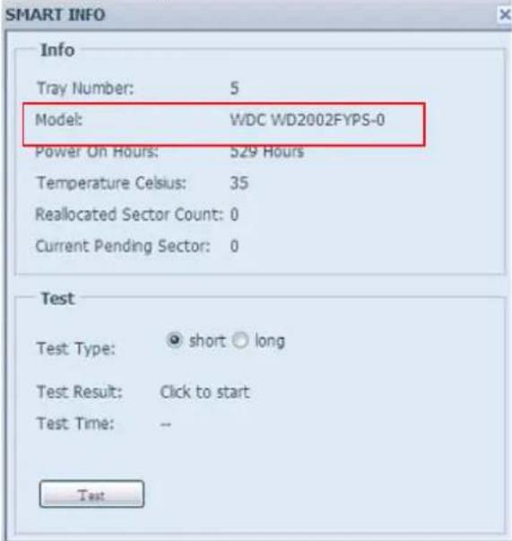
| S.M.A.R.T. Information | |
| Item Description | |
| Tray Number Tray the hard disk is installed in. | |
| Model Model name of the installed hard disk. | |
| Power ON Hours | Count of hours in power-on state. The raw value of this attribute shows total count of hours (or minutes, or seconds, depending on manufacturer) in power-on state. |
| Temperature Celsius The current temperature of the hard disk in degrees Celsius | |
| Reallocated Sector Count | Count of reallocated sectors. When the hard drive finds a read/write/verification error, it marks this sector as "reallocated" and transfers data to a special reserved area (spare area). This process is also known as remapping and "reallocated" sectors are called remaps. This is why, on a modern hard disks, you can not see "bad blocks" while testing the surface - all bad blocks are hidden in reallocated sectors. However, the more sectors that are reallocated, the more a decrease (up to 10% or more) can be noticed in disk read/write speeds. |
| Current Pending Sector | Current count of unstable sectors (waiting for remapping). The raw value of this attribute indicates the total number of sectors waiting for remapping. Later, when some of these sectors are rea successfully, the value is decreased. If errors still occur when reading sectors, the hard drive will try to restore the data, transfe it to the reserved disk area (spare area), and mark this sector as remapped. If this attribute value remains at zero, it indicates that the quality of the corresponding surface area is low. |
| Test Type Set short or long time to test. | |
| Test Result Result of the test. | |
| Test Time Total time of the test. | |
NOTE
If the Reallocated Sector Count > 32 or Current Pending Sector of a hard disk drive > 0, the status of the disk will show "Warning". This warning is only used to alert the system administrator that there are bad sectors on the disk, and they should replace those disks as soon as possible.
Bad Block Scan
On the Disks Information screen, you may also perform disk bad block scan, simply to click "Click to start" to start with. The result is only for reference and system will not take any action from its result.
| Disk No. | Capacity (MB) | Model | Firmware | Status | Bad Block Scan |
| 1 | 1,907,729 | WDC WD2002FYPS-0 | 04.0 | Click to start | |
| 2 | 1,907,729 | WDC WD2002FYPS-0 | 04.0 | Click to start | |
| 3 | 1,907,729 | WDC WD2002FYPS-0 | 04.0 | Click to start | |
| 4 | 1,907,729 | WDC WD2002FYPS-0 | 04.0 | Click to start | |
| 5 | 1,907,729 | WDC WD2002FYPS-0 | 04.0 | Click to start | |
| 6 | 1,907,729 | WDC WD2002FYPS-0 | 04.0 | Click to start | |
| 7 | 1,907,729 | WDC WD2002FYPS-0 | 04.0 | Click to start | |
| 8 | 1,907,729 | WDC WD2002FYPS-0 | 04.0 | Click to start | |
| Total Capacity: 15261832 (MB) | |||||
The testing result will be stay till system reboot with "Yet to start" displayed as default.
RAID Information
From the Storage menu, choose the RAID item and the RAID Information screen appears.
This screen lists the RAID volumes currently residing on the Thecus IP storage. From this screen, you can get information about the status of your RAID volumes, as well as the capacities allocated for data, and iSCSI. There is also a graph which represents how the RAID volume is currently allocated.
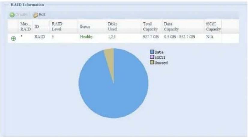
pie
RAID Information | Status | Total Capacity (GB) | | :--- | :--- | | RAID | 5 | | Healthy | 1,2.3 | | Data | 927.7 | | iSCSI | 0.3 GB / 852.7 GB | | Unused | N/A || RAID Information | |
| Item Description | |
| Master RAID The RAID | volume currently designated as the Master RAID volume. |
| ID ID of the current RAID volume. NOTE: All RAID IDs must be unique. | |
| RAID Level Shows the current RAID configuration. | |
| Status Indicates status | of the RAID. Can read either Healthy, Degraded, or Damaged. |
| Disks Used Hard disks used to form the current RAID volume. | |
| Total Capacity Total capacity of the current RAID. | |
| Data Capacity Indicates the used capacity and total capacity used by user data. | |
| iSCSI Capacity Indicates the capacity allocated to iSCSI. | |
Create a RAID
On the RAID Information screen, press the create button to go to the CREAT RAID screen. In addition to RAID disk information and status, this screen lets you make RAID configuration settings.
Using Create RAID, you can select stripe size, choose which disks are RAID disks or the Spare Disk.
| RAID Configurations | |
| Item Description | |
| Disk No. | Number assigned to the installed hard disks. |
| Capacity (MB) | Capacity of the installed hard disks. |
| Model | Model number of the installed hard disks. |
| Status Status of the installed hard disks. | |
| Used | If this is checked, current hard disk is a part of a RAID volume. |
| Spare | If this is checked, current hard disk is designated as a spare for a RAID volume. |
| Master RAID Check a box to designate this as the Master RAID volume. See theNOTEbelow for more information. | |
| Stripe Size This sets the | stripe size to maximize performance of sequential files in a storage volume. Keep the 64K setting unless you require a special file storage layout in the storage volume. A larger stripe size is better for large files. |
| Data Percentage The per | percentage of the RAID volume that will be used to store data. |
| Create Press this button | to configure a file system and create the RAID storage volume. |
To create a RAID volume, follow the steps below:
- On the RAID Information screen, click create.
- On the RAID Configuration screen, set the RAID storage space as JBOD, RAID 0, RAID 1, RAID 5, RAID 6, or RAID 10 — see Appendix B: RAID Basics for a detailed description of each.
- Specify a RAID ID.
- If this RAID volume is meant to be the Master RAID volume, tick the Master RAID checkbox.
NOTE
In a multiple RAID configuration, one RAID volume must be designated as the Master RAID volume. The Master RAID volume will store all installed modules. If the Master RAID is changed to another location (i.e. assigning volume 2 to be the Master RAID volume after volume 1 had been previously assigned), then all modules must be reinstalled. In addition, all system folders that were contained on the Master RAID volume will be invisible. Reassigning this volume to be the Master RAID will make these folders visible again.
- Selected whether the RAID volume will be encrypted or not. The RAID volume can protect data by using RAID Volume Encryption function to prevent the risk of data exposure. To activate this function, the Encryption option needs to be enabled while the RAID is created and followed by password input for identification. Also, an external writable USB disk plugged into any USB port on the system is required to save the password you have entered while the RAID volume is being created. See the screenshot below for details.
![RAID Information Create RAID Disk No. Capacity (MB) Model Status Used Spare 1 1,907,729 WDC WD2002... OK □ □ 2 1,907,729 WDC WD2002... OK □ □ 3 1,907,729 WDC WD2002... Warning □ □ 4 1,907,729 WDC WD2002... OK □ □ 5 1,907,729 WDC WD2002... OK □ □ 6 1,907,729 WDC WD2002... OK □ □ RAID Level: ○ JBOO ○ RAID 3 ○ RAID 1 ○ RAID 5 ○ RAID 6 ○ RAID 10 RAID ID: RAID (Allow 0~9, a~7, A~Z) □ Master RAID - Take effect after checked box Encryption: Password: [ Allow 1~16 characters ] Confirm Password: Quick Raid: ( Enable the setting to enhance RAID creation time if there is no partition existed inside of hard disk ) Stripe Size(KS): 64 Data Percentage: 95 % File System: EXIT Create](/content/2026/06/1184879/images/d823cb6b3a1545e7cb8d85759d4c48647d5fdda4b8bf96df5d8fbcd8ccb60606.jpg)
Once the Create button has been pressed with the Encryption checkbox enabled, the following message pop-up will appear for confirmation.
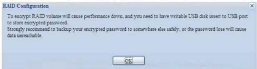
After the RAID volume has been created, you may remove this USB disk until the next time the system boots. The RAID volume can not be mounted if the USB disk with key can not be found in any system USB port when the volume is accessed. To activate the encrypted volume, plug the USB disk containing the encryption key and into any system USB port.
We are strongly recommended copying the RAID volume encryption key to a safe place. You can find the encryption key file from the USB disk in the following format:
(RAID volume created date)_xxxxx.key
WARNING
Please keep USB disk in a safe place and also backup the encrypted key. There is no way to rescue data back if the key is lost.
NOTE
- With RAID volume encryption enabled, the system performance will goes down.
- With RAID volume encryption enabled, RAID volume expansion will operate in off line mode.
RAID volumes with encryption enabled will be displayed with a key lock symbol next to volume ID name.
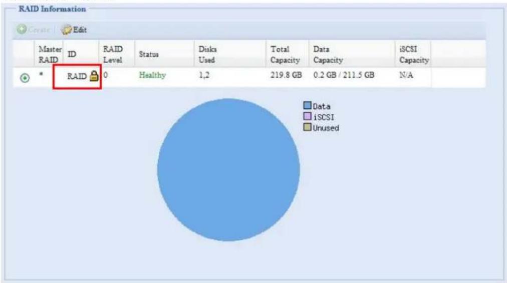
- Specify a stripe size — 64K is the default setting.
-
Specify the percentage allocated for user data by drag the horizontal bar. The remaining space will be made available for iSCSI.
-
Selected the file system you like to have for this RAID volume. The selection is available from ext3, XFS and ZFS.
NOTE
- Select ZFS file system while snapshot is needed. It is only one ZFS file system allowed to be created per system.
· ZFS file system is only accessible by CIFS/SMB, not for AFP and NFS users. - XFS file system is not support folder quota feature
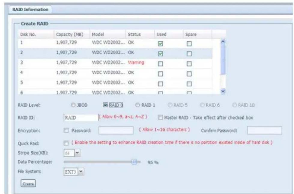
- Press Create to build the RAID storage volume.
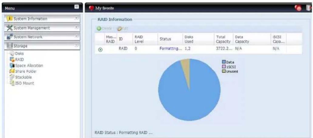
pie
RAID Status : Formatting RAID ...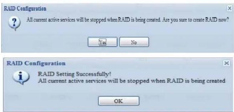
NOTE
Building a RAID volume may take time, depending on the size of hard drives and RAID mode. In general, while the RAID volume building process is up to "RAID Building" then the data volume is capable to be accessed.
WARNING
Creating RAID destroys all data in the current RAID volume. The data is unrecoverable.
With a RAID 1, RAID 5, or RAID 6 volume, you can also add a spare disk after the RAID is created.
See Chapter 6: Tips and Tricks > Adding a Spare Disk for details.
For more information on RAID, see Appendix B: RAID Basics.
RAID Level
You can set the storage volume as JBOD, RAID 0, RAID 1, RAID 5, RAID 6 or RAID 10. RAID configuration is usually required only when you first set up the device. A brief description of each RAID setting follows:
| RAID Levels | |
| Level Description | |
| JBOD The storage volume is a single HDD with no RAID support. JBOD requires a minimum of 1 disk. | |
| RAID 0 Provides data striping but no redundancy. Improves performance but not data safety. RAID 0 requires a minimum of 2 disks. | |
| RAID 1 Offers disk mirroring. Provides twice the read rate of single disks, but same write rate. RAID 1 requires a minimum of 2 disks. | |
| RAID 5 Data striping and stripe error correction information provided. RAID 5 requires a minimum of 3 disks. RAID 5 can sustain one failed disk. | |
| RAID 6 Two independent parity computations must be used in order to provide protection against double disk failure. Two different algorithms are employed to achieve this purpose. RAID 6 requires a minimum of 4 disks. RAID 6 can sustain two failed disks. | |
| RAID 10 RAID 10 has high reliability and high performance. RAID 10 is implemented as a striped array whose segments are RAID 1 arrays. It has the fault tolerance of RAID 1 and the performance of RAID 0. RAID 10 requires 4 disks. RAID 10 can sustain two failed disks. |
WARNING
If the administrator improperly removes a hard disk that should not be removed when RAID status is degraded, all data will be lost.
Edit RAID
On the RAID Information screen, press the Edit button to go to the RAID Information screen.
Using Edit RAID, you can select RAID ID and the Spare Disk.
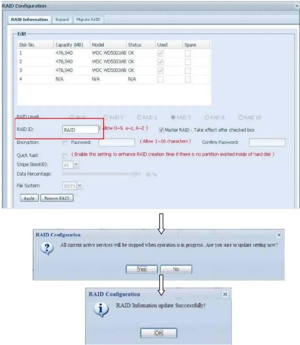
Remove RAID
Click to remove the RAID volume. All user data and iSCSI has been created in selected RAID volume will be removed.
To remove a RAID volume, follow the steps below:
- On the RAID List screen, select the RAID volume by clicking on its radio button, and click RAID Information to open the RAID Configuration screen.
- On the RAID Configuration screen, click Remove RAID.
- The confirmation screen appear, you will have to input "Yes" with exactly wording case to complete "Remove RAID" operation
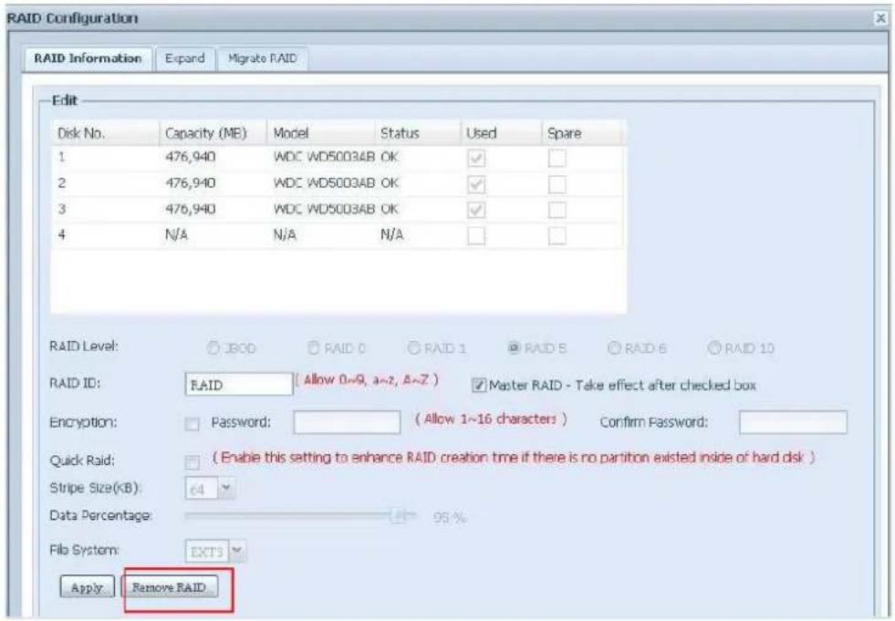
WARNING
Remove RAID destroys all data in the current RAID volume. The data is unrecoverable.
Expanding a RAID
To expand a RAID 1, RAID 5, or RAID 6 volume, follow the steps below:
- Replace one of the hard drives in the RAID volume and allow it to automatically rebuild.
- Once rebuilt, you can continue to replace any remaining disks in the RAID array.
- When you are done replacing hard drives, log on to Web Management. Navigate to Storage> RAID to open the RAID Configuration screen.
-
On the RAID Information screen, and click Edit to open the RAID Configuration screen.
-
On the RAID Configuration screen, click Expand.
NOTE
RAID expansion did not support file system created by ZFS.
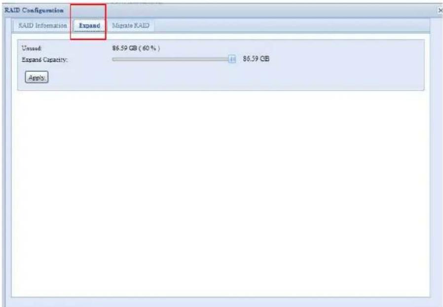
Migrating a RAID
Once a RAID volume has been created, you may want to move it to other physical drives or change the RAID array all together. To migrate a RAID 0, RAID 1, RAID 5 or RAID 6 volume, follow the steps below:
- From the RAID Configuration screen, click Migrate RAID.
- A list of possible RAID migration configurations will be listed. Select the desired migration scheme and click Apply.
- The system will begin migrating the RAID volume.
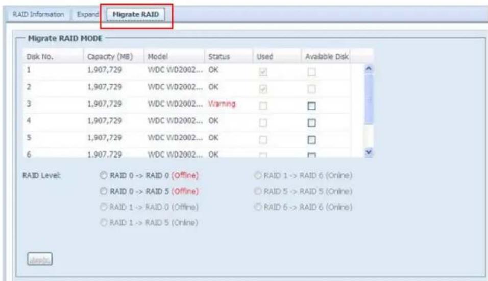
![RAID Configuration Warning! RAID migration may take several hours to complete depending on the RAID capacity. Are you sure? Yes No RAID Configuration To avoid disaster data lost caused by power failure, a full data backup is strongly recommended. Please type in [ Yes ] below to proceed. Yes OK Cancel RAID Configuration RAID Setting Successfully! You are in on_line Migration NOW!! OK](/content/2026/06/1184879/images/eb89107720a9c7a2605453ab58629202105156fa771475395b651707e22fd368.jpg)
NOTE
Migrating a RAID volume could take several hours to complete
With RAID level migration function, the limitation as listed below.
- During RAID level migration, it is not allowed reboot or shutdown system.
- The RAID migration from R1 to R5 or R1 to R6, the all services will restart and volumes "iSCSI" is read only but "user data" is capable read / write during operation.
NOTE
The migration scheme below is based on ThecusIP Storage series products in maximum possible combination. The other model which has less HDD supported can refer web UI while RAID migration operated.
Below is a table listing of possible RAID migration schemes:
| To From | RAID 0 RAID 5 RAID | 6 | |
| RAID 1 | [RAID 1] HDDx2 to [RAID 5] HDDx3 | [RAID 1] HDDx2 to [RAID 5] HDDx4[RAID 1] HDDx2 to [RAID 5] HDDx5[RAID 1] HDDx2 to [RAID 5] HDDx6[RAID 1] HDDx2 to [RAID 5] HDDx7[RAID 1] HDDx2 to [RAID 5] HDDx8......HDDx16[RAID 1] HDDx3 to [RAID 5] HDDx4[RAID 1] HDDx3 to [RAID 5] HDDx5[RAID 1] HDDx3 to [RAID 5] HDDx6[RAID 1] HDDx3 to [RAID 5] HDDx7[RAID 1] HDDx3 to [RAID 5] HDDx8......HDDx16[RAID 1] HDDx4 to [RAID 5] HDDx5[RAID 1] HDDx4 to [RAID 5] HDDx6[RAID 1] HDDx4 to [RAID 5] HDDx7[RAID 1] HDDx4 to [RAID 5] HDDx8......HDDx16[RAID 1] HDDx5 to [RAID 5] HDDx6[RAID 1] HDDx5 to [RAID 5] HDDx7[RAID 1] HDDx5 to [RAID 5] HDDx8......HDDx16[RAID 1] HDDx6 to [RAID 5] HDDx7[RAID 1] HDDx6 to [RAID 5] HDDx8......HDDx16[RAID 1] HDDx7 to [RAID 5] HDDx8......HDDx16 | [RAID 1] HDDx2 to [RAID 6] HDDx4[RAID 1] HDDx2 to [RAID 6] HDDx5[RAID 1] HDDx2 to [RAID 6] HDDx6[RAID 1] HDDx2 to [RAID 6] HDDx7[RAID 1] HDDx2 to [RAID 6] HDDx8......HDDx16[RAID 1] HDDx3 to [RAID 6] HDDx4[RAID 1] HDDx3 to [RAID 6] HDDx5[RAID 1] HDDx3 to [RAID 6] HDDx6[RAID 1] HDDx3 to [RAID 6] HDDx7[RAID 1] HDDx3 to [RAID 6] HDDx8......HDDx16[RAID 1] HDDx4 to [RAID 6] HDDx5[RAID 1] HDDx4 to [RAID 6] HDDx6[RAID 1] HDDx4 to [RAID 6] HDDx7[RAID 1] HDDx4 to [RAID 6] HDDx8......HDDx16[RAID 1] HDDx5 to [RAID 6] HDDx6[RAID 1] HDDx5 to [RAID 6] HDDx7[RAID 1] HDDx5 to [RAID 6] HDDx8......HDDx16[RAID 1] HDDx6 to [RAID 6] HDDx7[RAID 1] HDDx6 to [RAID 6] HDDx8......HDDx16[RAID 1] HDDx7 to [RAID 6] HDDx8......HDDx16 |
| RAID 5 | X [RAID 5] HDDx3 to [RAID 5] HDDx4 | [RAID 5] HDDx3 to [RAID 5] HDDx5[RAID 5] HDDx3 to [RAID 5] HDDx6[RAID 5] HDDx3 to [RAID 5] HDDx7[RAID 5] HDDx3 to [RAID 5] HDDx8......HDDx16[RAID 5] HDDx4 to [RAID 5] HDDx5[RAID 5] HDDx4 to [RAID 5] HDDx6[RAID 5] HDDx4 to [RAID 5] HDDx7[RAID 5] HDDx4 to [RAID 5] HDDx8......HDDx16[RAID 5] HDDx5 to [RAID 5] HDDx6[RAID 5] HDDx5 to [RAID 5] HDDx7[RAID 5] HDDx5 to [RAID 5] HDDx8......HDDx16[RAID 5] HDDx6 to [RAID 5] HDDx7[RAID 5] HDDx6 to [RAID 5] HDDx8......HDDx16[RAID 6] HDDx7 to [RAID 6] HDDx8......HDDx16 | X |
| RAID6 | X X [ONLINE] | [RAID 6] HDDx4 to [RAID 6] HDDx5[RAID 6] HDDx4 to [RAID 6] HDDx6[RAID 6] HDDx4 to [RAID 6] HDDx7[RAID 6] HDDx4 to [RAID 6] HDDx8......HDDx16[RAID 6] HDDx5 to [RAID 6] HDDx6[RAID 6] HDDx5 to [RAID 6] HDDx7[RAID 6] HDDx5 to [RAID 6] HDDx8......HDDx16[RAID 6] HDDx6 to [RAID 6] HDDx7[RAID 6] HDDx6 to [RAID 6] HDDx8......HDDx16[RAID 6] HDDx7 to [RAID 6] HDDx8......HDDx16 |
Space Allocation
iSCSI Target
You may specify the space allocated for iSCSI or target USB volumes (target USB is available in model N5500 and 1U4600). The iSCSI volume can be created from 5 to 25 volumes per system depend on Thecus IP storage's model.
| Model N0503 | N3200XXX | N4200 seriesN2200XXXN5200XXX1U4200XXXN8200XXX | N55001U4600 | N7700N7700+N8800N8800+ | N7700PRON7700SASN8800PRON8800SAS |
| Allow iSCSIVolume | 5 10 10 1 | 5 25 |
To do this, under the Storage menu, click RAID and the RAID List window appears. Select the RAID volume you wish to reallocate by clicking on its radio button, and click Space Allocation. The RAID Information and Volume Allocation List windows will appear.
The Volume Allocation List displays the space allocated for iSCSI volumes on the current RAID volume.
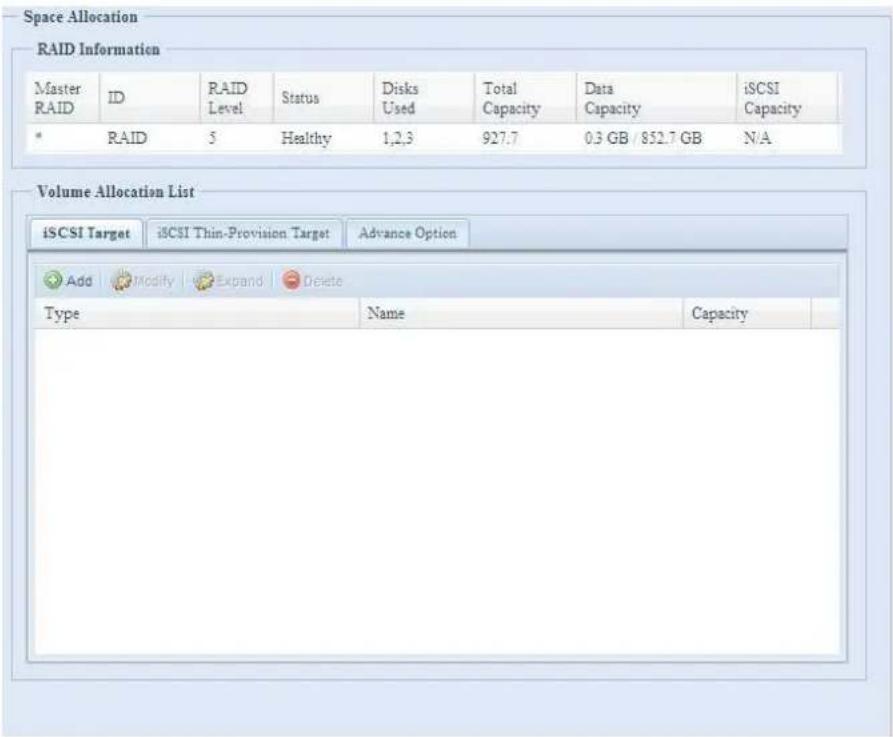
| Volume Allocation List | |
| Item Description | |
| Modify Click this to modify the allocated space. | |
| Delete Click this to delete the allocated space. | |
| iSCSI Target Click to allocate space to iSCSI volume. | |
| Type Type of volume. Can be either USB or iSCSI. | |
| Name Name assigned to the volume. | |
| Capacity Capacity of the allocated space. |
Allocating Space for iSCSI Volume
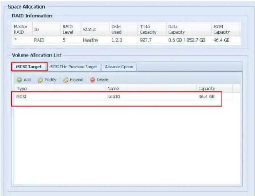
To allocate space for an iSCSI volume on the current RAID volume, follow the steps below:
- Under the Volume Allocation List, select iSCSI Target then click Add. The Create iSCSI Volume screen appears.
![Space Allocation Create iSCSI Volume RAID ID: RAID Unused: 5 % (46.38 GB) Allocation: 46.38 GB iSCSI Target Volume: Enable Disable Target Name: Limit:(0~9, a~z) ign_Year: 2010 ign_Month: 12 LUN ID: 1 Authentication: None CHAP Username: Limit:(0~9, a~z, A~Z) Password: Limit:(0~9, a~z, A~Z,length between 12~16) Password Confirm: OK Description The iSCSI block size can be set under system advance option, default is 512 Bytes. Please use [ 4K ] block size while more than 2TB capacity will be configured in Windows XP. Please use [ 512 Bytes ] block size for application like VMware etc.](/content/2026/06/1184879/images/6df55f2118a6b7ae9257c44f0f498d15dead6347fc7a39ca536f6af9f2b64049.jpg)
| Create iSCSI Volume | |
| Item Description | |
| RAID ID ID of current | RAID volume. |
| Allocation Percentage | and amount of space allocated to iSCSI volume. |
| Unused Percentage and | amount of unused space on current RAID volume. |
| iSCSI Target Volume | Enable or Disable the iSCSI Target Volume. |
| Target Name Name of | the iSCSI Target. This name will be used by the Stackable NAS function to identify this export share. |
| Year Select the current year from the dropdown. | |
| Authentication You may choose CHAP authentication or choose None. | |
| Month Select the current month from the dropdown. | |
| LUN ID Specific Logic | unit ID number. |
| Username | Enter a username. |
| Password | Enter a password. |
| Password Confirm | Reenter the chosen password |
- Designate the percentage to be allocated from the Allocation drag bar.
- Enable the iSCSI Target Service by selecting Enable.
- Choose to enable CHAP authentication or choose None.
- Enter a Target Name. This will be used by the Stackable NAS function to identify this export share.
- Choose the current year from the Year dropdown.
-
Choose the current month from the Month dropdown.
-
When iSCSI target volume has been created, the LUN ID is configurable from 1 to 254 with a default of the next available number in ascending numerical order. The LUN ID is unique and can not be duplicated except for LUN ID 0.
- If you've enabled CHAP authentication, enter a username and a password. Confirm your chosen password be reentering it in the Password Confirm box.
- Click OK to create the iSCSI volume.
Modify iSCSI Volume
To Modify iSCSI volume on the current RAID volume, follow the steps below:
1. Under the Volume Allocation List, click Modify.
The Modify iSCSI Volume screen appears.
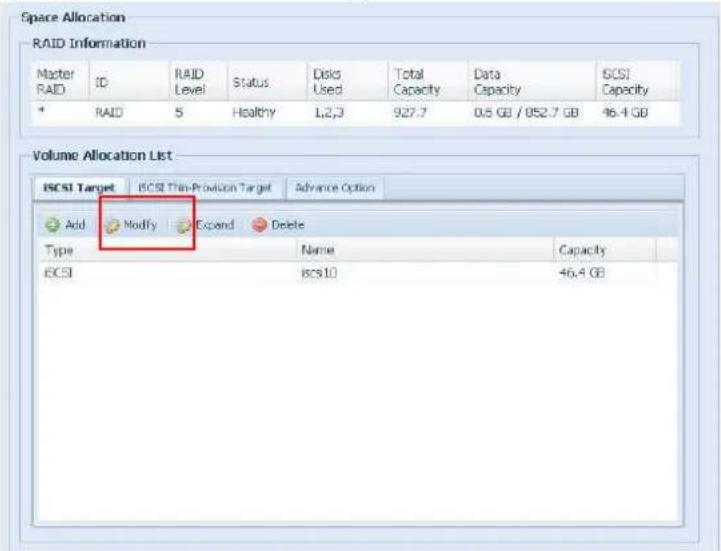
![Space Allocation Create iSCSI Volume RAID ID: RAID Unused: 4 % (148.88 GB) Allocation: 148.88 GB iSCSI Target Volume: Enable Disable Target Name: Limit:(0~9, a~z) ign_Year: 2010 ign_Month: 08 LUN ID: 2 Authentication: None CHAP Username: Limit:(0~9, a~z, A~Z) Password: Limit:(0~9, a~z, A~Z, length between 12~16) Password Confirm: OK Description The iSCSI block size can be set under system advance option, default is 512 Bytes. Please use [ 4K ] block size while more than 2TB capacity will be configured in Windows XP. Please use [ 512 Bytes ] block size for application like VMware etc.](/content/2026/06/1184879/images/0c144631c3d9aca67f64b4f6cfbd145533f1f06b769cb68c8a73e276be8c4984.jpg)
- Modify your setting. Press ok to change.
Expand Volume
The iSCSI volume is now able to expand its capacity from unused space. From the volume list, simply select the iSCSI volume you like to expand and click the Expand button:
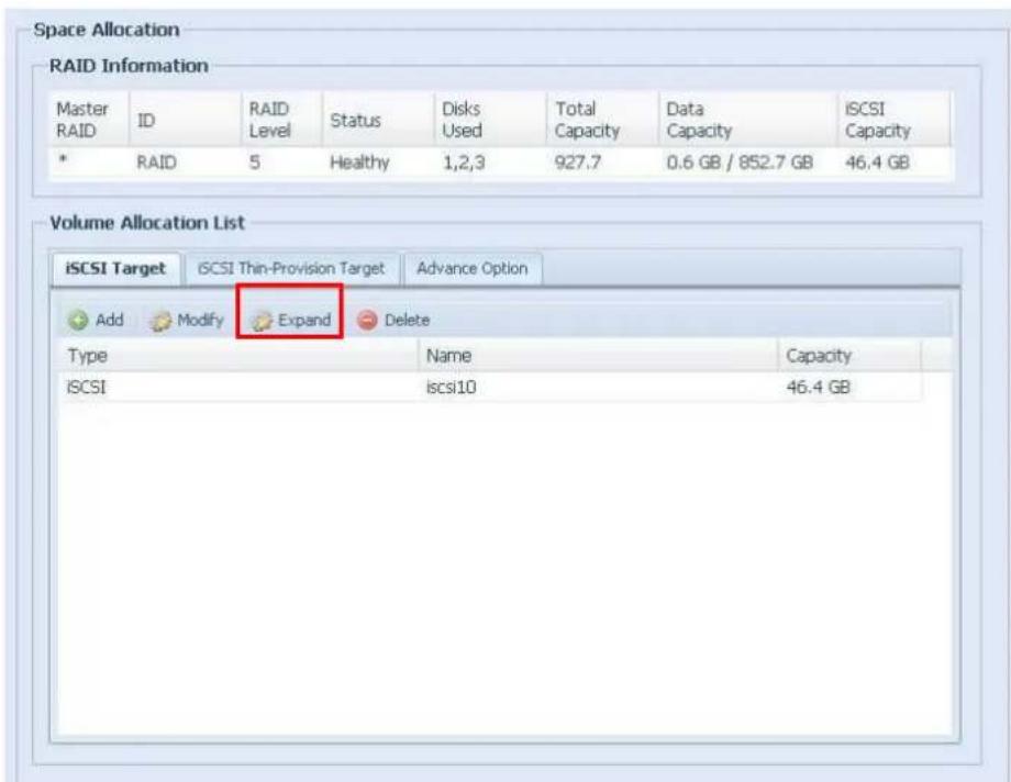
You will then see the dialog box displayed below. Drag the Expand Capacity bar to the size you want. Then press Expand to confirm the operation.
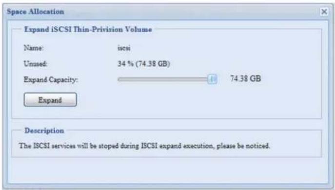
Delete Volume
To delete volume on the current RAID volume, follow the steps below:
- Under the Volume Allocation List, click Delete. The Space Allocation screen appears.
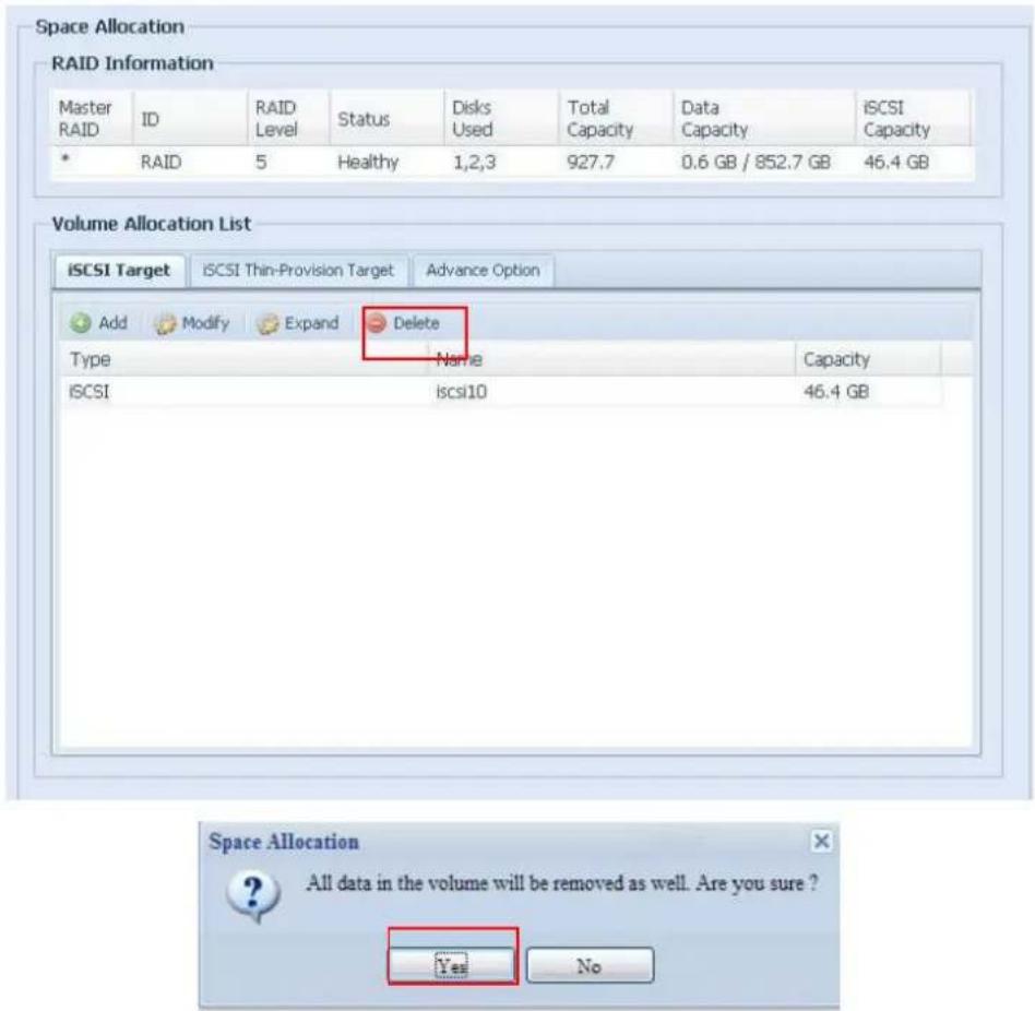
- Press YES. All data in the volume will be removed.
iSCSI Thin-Provisioning
With this function, the iSCSI capacity can be more flexible and more efficiently serve more users.
The idea for iSCSI thin-provisioning is sharing the available physical capacity to a number of iSCSI target volumes and also setup virtual capacity to expand the physical size while it needed.
To setup iSCSI thin-provisioning, go to Space Allocation under the Storage category. The iSCSI thin-provisioning volume needs to be created first. Simply click iSCSI Thin-Provision Target. You can refer the screen shot below.
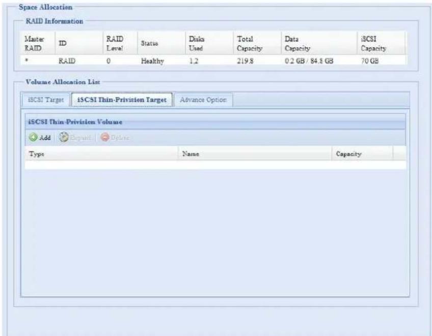
Next, setup the physical capacity for iSCSI thin-provision volume by dragging the Allocation bar to the desired size.
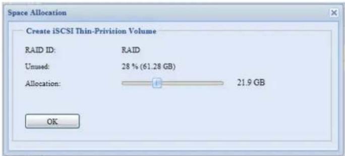
After the size has been determined, click OK to confirm. Now you will see the iSCSI thin-provisioning volume is available from the list. Please refer to the screenshot below.
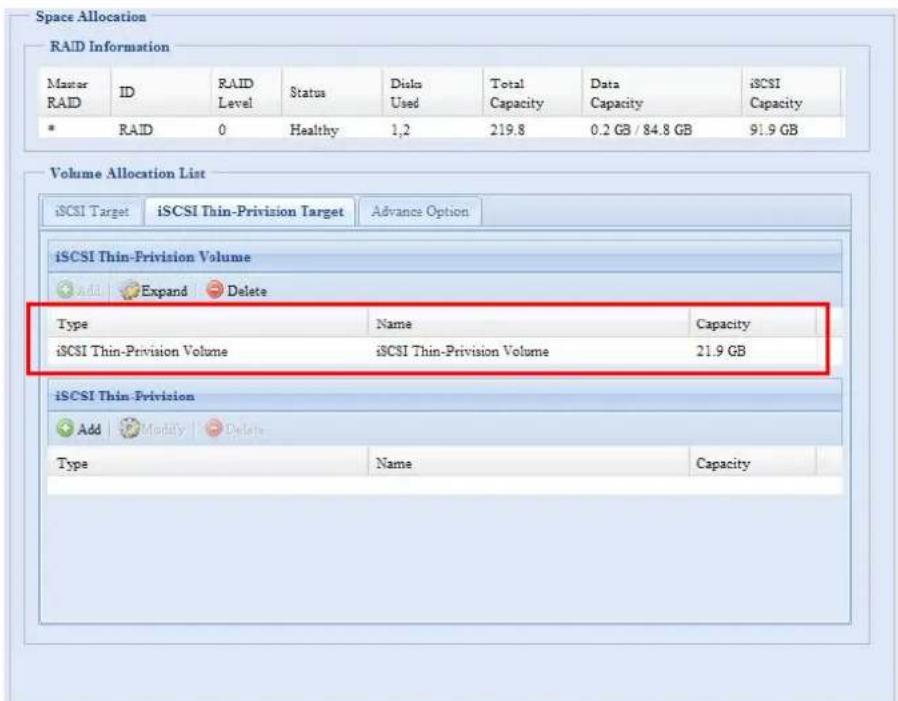
NOTE
1. Each RAID volume can only create one iSCSI thin-provision volume. 2. Each thin-provision volume can only create 5 iSCSI target volumes. 3. The notification will send out while the physical size of iSCSI thin-provision capacity has used up to 90%.Advance Option
There are 2 options is currently allow Admin to Enable/Disable to operate Thecus IP storage associated with iSCSI setting. The details as listed in following screenshot. With the option changed, it will need to reboot system to activate.  iSCSI Block Size
Select the block size with 4K while the iSCSI volume size is over 2TB.iSCSI CRC/Checksum
To enable this option, the initiator can connect with "Data digest" and "Header digest" enabled. Stackable NAS
The Thecus IP storage's capacity can be expanded even further using the stackable function. With it, users can expand the capacity of their network storage systems up to 5 other stack target volumes which are located in different systems. These can be stacked through single network access like SMB or AFP acting as a share folder type. flowchart
graph LR
    A["Server"] --> B["HUB/Switch"]
    B --> C["Capacity Expansion"]
    C --> D["Server 1: 1 Target device volume available"]
    C --> E["Server 2: 2 Target device volume available"]
    C --> F["Server 3: 1 Target device volume available"]
    G["Configuration to act as Stack Master"] --> B
    H["Available target device from 1U4500 / N5200 PRO"] --> D
    I["Can connect total 5 Thecus target device. Up to 20 TB capacity."] --> F
A. Add a Stack Target Volume
From the figure above, click Add to access the stackable target device configuration page. Please refer to the figure below: With the added stack target you could "Enable" or "Disable" now or later per usage needed.  Next, input the target IP address of the stackable device and click the Discovery button. The system will list available target volumes from the inputted IP address. Once IP with volume have been set, you may need to input a valid user name and password to validate your access rights. If there is no user name and password needed to access target volume, then leave it blank.  The Export share name will become the network share name and displayed through network access such as SMB. You may refer the figures below to see the result. Please note the naming limitation.  From the figure above, the Export share name is "pmmeeting". The figures below show the result before and after via Microsoft Network Access with settings have been completed.   The Browseable setting will be same method of setting for system share folder. It designates whether or not this folder will be visible through web disk. You may refer the figures below for reference when Yes and No are selected.  The Public setting will be set same as what the setting for the system share folder associated with the ACL permission setup. If Public is set to Yes, all users will be able to access it, and ACL button will be grayed out. If Public is set to No, the ACL button will be available on the Stack Target List window.  Click Apply to save your changes.B. Activate a Stack Target
After your settings have been applied, the system will bring you back to Stack Target List window as shown below. There is one stack target device has been attached into this stack master.   With this newly attached stack target device, you will see the information displayed and also several options you can choose. In general, if attached stack target device has been used by another N5200PRO/1U4500/N5500/N8800 series as stack target volume, then the Format item will be displayed and system will recognize it straight away and display its capacity. Otherwise, the Format item will be available and the Capacity and Status items will show as "N/A" and "Unknown file system" respectively. Next, click Format to proceed with formatting. After the format is complete, the stack target volume will be created successfully. You will see the volume's capacity and status in the Stack Target List screen.C. Edit a Stack Target
To make any changes to stack targets, click Edit for the corresponding stack target, and system will bring up the following dialogue:  After your changes have been made, click Apply to confirm any modifications. Once changes are applied, the associated information will be updated on the Stack Target List window.D. Stack Target ACL
If the stack target Public setting set to Yes, then the ACL button will be grayed out. However, if Public setting is set to No, then the ACL button will be available for you to setup user access permissions for the stack target. ACL settings will be exactly the same as system folder that you may have setup previously. E. Reconnect a Stack Target
The enabled stack target devices may be disconnected by situations such as power outages or network disconnects. When this happens, the Reconnect button will available. To attempt to reconnect the stack target, click Reconnect.  ISO Mount
The ISO Mount feature is very useful tool from Thecus products. With it, users can mount an ISO file and having export name to display all details from mounted ISO file. From the main menu, the ISO Mount feature is located under "Storage". Please refer the figure below for reference. Select on the ISO mount function and you will have the screen shot appear as following. A. Add a ISO file
From the figure above, select ISO file from drop down share list.  After selection, system will bring up Mount table for further setting screen.   To mount new ISO file, select from listed ISO file and input desired mounting name into "Mount as:" field. Click "ADD" with confirmation to complete mounting ISO file. Or without "Mount as" ISO file export name input, system will automatic to give the export name by ISO file name. If left "Mount as:" blink then system will create mount point by ISO file name.  After you have completed to add ISO then the page will displayed all mounted ISO files,  You could click "Unmount" to eliminate mounted ISO file.B. Using ISO
The mounted ISO file will be located same share folder with name giving. Please refer the screen shot below. ISO file "image" has mounted as folder "Image" you could see. The ISO file "Thecus 01" without assign mounting name, system automatically has folder "Thecus 01" created. Share Folder
From the Storage menu, choose Share Folder, and the Folder screen appears. This screen allows you to create and configure folders on the Thecus IP storage volume. Adding Folders
On the Folder screen, press the Add button and the Add Folder screen appears. This screen allows you to add a folder. After entering the information, press Apply to create new folder. | Add Folder | |
| Item Description | |
| RAID ID RAID volume | where the new folder will reside. |
| Folder Name Enter the | name of the folder. |
| Description Provide a description the folder. | |
| Browseable Enable or disable users from browsing the folder contents. If Yes is selected, then the share folder will be browseable. | |
| Public | Admit or deny public access to this folder. If Yes is selected, then users do not need to have access permission to write to this folde When accessing a public folder via FTP, the behavior is similar to anonymous FTP. Anonymous users can upload/download a file to the folder, but they cannot delete a file from the folder. |
| Share Folder Limit Enter the maximum size of the folder in Gigabytes (GB). The folder cannot grow beyond this limit. You can enter a 0 to turn off the share folder limit.This option did not apply while XFS file system selected. | |
| Apply Press Apply to create the folder. | |
NOTE
Folder names are limited to 60 characters. Systems running Windows 98 or earlier may not support file names longer than 15 characters.Modify Folders
On the Folder screen, press the Edit button and the Modify Folder screen appears. This screen allows you to change folder information. After entering the information, press Apply to save your changes. | Modify Folder | |
| Item Description | |
| RAID ID RAID volume | where the folder will reside. |
| Folder Name Enter the | name of the folder. |
| Description Provide a description the folder. | |
| Browseable Enable or disable users from browsing the folder contents. This setting will only apply while access via SMB/CIFS and web disk. | |
| Public Admit or deny public access to this folder. | |
| Share Limit Enter the maximum size of the folder. The folder will not grow beyond this limit. You can enter a 0 to turn off the share folder limit. | |
Remove Folders
To remove a folder, press the Remove button from the specified folder row. The system will confirm folder deletion. Press Yes to delete the folder permanently or No to go back to the folder list. WARNING
All the data stored in the folder will be deleted once the folder is deleted. The data will not be recoverable.NFS Share
To allow NFS access to the share folder, enable the NFS Service, and then set up hosts with access rights by clicking Add.  | NFS Share | |
| Item Description | |
| Hostname Enter the name or IP address of the host | |
| Privilege Host has either read only or writeable access to the folder. | |
| Guest System Support | There are two selections available:Unix / Linux SystemAIX (Allow source port > 1024)Choose the one which best fits your needs. |
| IO Mapping There are three selections available: | |
| Guest system root account will have full access to this share (root:root).Guest system root account will be mapped to anonymous user (nobody:nogroup) on NAS.All user on guest system will be mapped to anonymous user (nobody:nogroup) on NAS.Choose the one which best fits your needs. | |
| Apply Click to save your changes. | |
Snapshot
The Thecus IP storage is capable for 16 snapshot version control. To have snapshot to work on, the file system creation for RAID volume has to be "ZFS". Snap (Snapshot configuration)
If added folder has located in the RAID volume with "ZFS" file system, then the folder management screen with "Snap" button will be configurable. | Snapshot | |
| Item Description | |
| Take Shot Click to take | snapshot right away. |
| Remove Click to remove | e snapshot schedule. |
| Schedule Click to open | snapshot schedule setup screen. |
Folder and sub-folders Access Control List (ACL)
On the Folder screen, press the ACL button, and the ACL setting screen appears. This screen allows you to configure access to the specific folder and sub-folders for users and groups. Select a user or a group from the left hand column and then choose Deny, Read Only, or Writable to configure their access level. Press the Apply button to confirm your settings.  | ACL setting | |
| Item Description | |
| Deny Denies access to | users or groups who are displayed in this column. |
| Read Only Provides Read | Only access to users or groups who are displayed in this column. |
| Writable Provides Write | access to users or groups who are displayed in this column. |
| Recursive Enable to inherit the access right for all its sub-folders. | |
NOTE
If one user has belonged to more than one group but different privilege than the priority Deny > Read Only > Writable To setup sub-folders ACL, click on "1" symbol to extract sub folders list as screen shot shows below. You may carry on with same steps as share level ACL setting. NOTE
The ACL can be set for share and sub-folders level, not for files. The ACL screen also allows you to search for a particular user. To do this, follow the steps below: 1. In the blank, enter the name of the user you would like to find. 2. From the drop down select the group you would like to search for the user in. 3. Click Search.  NOTE
The system will list up to 1,000 users from the chosen category. To narrow your search, enter a search term in the blank provided.User and Group Authentication
The Thecus IP storage has built-in user database that allows administrators to manage user access using different group policies. From the User and Group Authentication menu, you can create, modify, and delete users, and assign them to groups that you designate. ADS/NT Support
If you have a Windows Active Directory Server (ADS) or Windows NT server to handle the domain security in your network, you can simply enable the ADS/NT support feature; the Thecus IP storage will connect with the ADS/NT server and get all the information of the domain users and groups automatically. From the Accounts menu, choose Authentication item and the ADS/NT Support screen appears. You can to change any of these items and press Apply to confirm your settings.  A description of each item follows:| ADS/NT Support | |
| Item Description | |
| Work Group / Domain Name | Specifies the SMB/CIFS Work Group / ADS Domain Name (e.g. MYGROUP). |
| ADS/NT Support Select | Disable to disable authentication through Windows Active Directory Server or Windows NT. |
| Authentication Method | Select ADS for Windows Active Directory Server, or select NT for Windows NT |
| ADS/NT Server Name | Specifies the ADS/NT server name (e.g. adservername). |
| ADS/NT Realm Specifies the ADS/NT realm (e.g. example.com). | |
| Administrator ID Enter | the administrators ID of Windows Active Directory or Windows NT, which is required for Thecus IP storage to join domain. |
| Administrator Password | Enter the ADS/NT Administrator password. |
| Apply To save your settings. | |
| AD Domain Example | |
| Item Information | |
| Work Group / Domain Name | domain |
| ADS Support Enable | |
| ADS Server Name Computer1 | |
| ADS/NT Realm Domain,local | |
| Administrator ID Administrator | |
| Administrator Password | ********** |
NOTE
- The DNS server specified in the WAN/LAN1 configuration page should be able to correctly resolve the ADS server name. - The time zone setting between Thecus IP storage and ADS should be identical. - The system time difference between Thecus IP storage and ADS should be less than five minutes. - The Administrator Password field is for the password of ADS (Active Directory Server) not Thecus IP storage.Local User Configuration
From the Accounts menu, choose the User item, and the Local User Configuration screen appears. This screen allows you to Add, Edit, and Remove local users. | Local User Configuration | |
| Item Description | |
| Add Press the Add button to add a user to the list of local users. | |
| Edit Press the Edit button to modify a local user. | |
| Remove Press the Remove button to delete a selected user from the system. |
Add Users
1. Click on the Add button on Local User Configuration screen, and Local User Setting screen appears. 2. On the Local User Setting screen, enter a name in the User Name box. 3. Enter a User ID number. If left blank, the system will automatically assign one. 4. Enter a password in the Password box and re-enter the password in the Confirm box. 5. Select which group the user will belong to. Group Members is a list of groups this user belongs to. Group List is a list of groups this user does not belong to. Use the << or >> buttons to have this user join or leave a group. 6. Press the Apply button and the user is created. NOTE
All users are automatically assigned to the 'users' group.Edit Users
1. Select an existing user from the Local User Configuration screen. 2. Click on the Edit button, and Local User Setting screen appears. 3. From here, you can enter a new password and re-enter to confirm, or use the << or >> buttons to have this user join or leave a group. Click the Apply button to save your changes. Remove Users
1. Select an existing user from the Local User Configuration screen. 2. Click on Remove button and the user is deleted from the system. Local Group Configuration
From the Accounts menu, choose the Group item, and the Local Group Configuration screen appears. This screen allows you to Add, Edit, and Remove local groups. | Local Group Configuration | |
| Item Description | |
| Add Press the Add button to add a user to the list of local groups. | |
| Edit | Press the Edit button to modify a selected group from the system. |
| Remove Press the Remove button to delete a selected group from the system. | |
Add Groups
1. On the Local Group Configuration screen, click on the Add button. 2. The Local Group Setting screen appears. 3. Enter a Group Name. 4. Enter a Group ID number. If left blank, the system will automatically assign one. 5. Select users to be in this group from the Users List by adding them to the Members List using the << button. 6. Click the Apply button to save your changes. Edit Groups
1. On the Local Group Configuration screen, select a group name from the list. 2. Press the Edit button to modify the members in a group. 3. To add a user into a group, select the user from the Users List, and press the << button to move the user into the Members List. 4. To remove a user from a group, select the user from Members List, and press the >> button. 5. Click the Apply button to save your changes. Remove Groups
1. On the Local Group Configuration screen, select a group name from the list. 2. Press Remove to delete the group from the system. Batch Create Users and Groups
The Thecus IP storage can also add users and groups in batch mode. This enables you to conveniently add numerous users and groups automatically by importing a simple comma-separated plain text (\*.txt) file. From the Accounts menu, click Batch Mgmt and the Batch Create Users and Groups dialogue will appear. To import your list of users and groups, follow these steps: 1. Click Browse... to locate your comma-separated text file. The information in the text file should follow this format: [USERNAME], [PASSWORD], [GROUP] 2. Click Open. 3. Click Import to begin the user list import. Quota
The User Quota system provides a way of limiting users' available storage capacity. Setting a user quota gives a given user a given amount of space on EACH RAID partition. For example, if there are 3 RAID partitions and a user has a user quota of 300MB, the user can store 300MB of data on EACH RAID partition, or a total of 900MB of data. The framework keeps track of the total amount of data a user has used across different folders and functions such as the photo server. Network Service
Setup and manage protocols such as Samba/CIFS, FTP, and HTTP/Web Disk, and other network services. Samba / CIFS
There are 5 options is currently allow Admin to Enable/Disable to operate Thecus IP storage associated with Samba / CIFS protocol. With the option changed, it will need to reboot system to activate. Samba Service
Used for letting the operating system of UNIX series and SMB/CIFS of Microsoft Windows operating system (Server Message Block / Common Internet File System). Do the link in network protocol. Enable or Disable SMB/CIFS protocol for Windows, Apple, Unix drive mapping.NOTE
\- In some environments, due to security concerns, you may wish to disable SMB/CIFS as a precaution against computer viruses.File Access Cache
File Access Cache is default Enable. This option will help to increase the performance while single client access share folder in writing under SMB/CIFS protocol.Samba Recycle Bin
The Thecus IP storage is supported recycle bin via SMB/CIFS protocol. Simply enable it then all of deleted files/folders will reside in the ".recycle" folder with hidden attribution in each share.   In general, Windows has default to invisible all of hidden folders/files. So please enable this option to view ".recycle" folder.Samba Anonymous Login Authentication
To enable this option, no matter there is share folder has been created in public access. The user account and password is needed from system to access under SMB/CIFS protocol. On the other hand, no more anonymous login is allowed.Samba is Native mode
The Thecus IP storage is supported Samba mode options. In the ADS environment with "Native" mode selected then Thecus IP storage is capable to become local master position.UNIX Extension
The default is enable for Samba usage, with situation using Mac OSX with smb connection may have permission issue. When it happened, please setup "UNIX Extension" disable to get issue solved.AFP (Apple Network Setup)
From the Network Service menu, choose the AFP item, and the AFP Support screen appears. This screen displays the configuration items for the Apple Filing Protocol. You can change any of these items and press Apply to confirm your settings.  A description of each item follows:| Apple Network Configuration | |
| Item Description | |
| AFP Server Enable or disable Apple File Service to use Thecus IP storage with MAC OS-based systems. | |
| MAC CHARSET Specifics the code page from drop down list | |
| Zone Specifies Zone for Applet Talk service.If your AppleTalk network uses extended networks and is assigne with multiple zones, assign a zone name to Thecus IP storage. If you do not want to assign a network zone, enter an asterisk (*) to use the default setting. | |
| Time Machine Enable checked box while you like to backup you MAC system to have Thecus IP storage as MAC time machine |
NFS Setup
From the Network Service menu, choose the NFS item, and the NFS Support screen appears. The Thecus IP storage can act as an NFS server, enabling users to download and upload files with the favorite NFS clients. Press Apply to confirm your settings.  A description of each item follows:| NFS Server Setting | |
| Item Description | |
| NFS | Enable or Disable NFS support. |
| Apply Click Apply to save your changes. | |
FTP
Thecus IP storage can act as a FTP server, enabling users to download and upload files with their favorite FTP programs. From the Network Service menu, choose the FTP item, and the FTP screen appears. You can change any of these items and press Apply to confirm your settings.  A description of each item follows:| FTP | |
| Item Description | |
| FTP Enable FTP Service | on Thecus IP storage. |
| Security FTP Enable or | or disable Security FTP, be sure the client FTP software has also security FTP setting enabled. |
| Port Specifies the port | number of an incoming connection on a non-standard port. |
| FTP ENCODE If your FTP | client or operating system does not support Unicode (e.g. Windows® 95/98/ME or MAC OS9/8), select the same encoding as your OS here in order to properly view the files and directories on the server. Available options are BIG5, HZ, GB2312, GB18030, ISO, EUC-JP, SHIFT-JIS and UTF-8. |
| Allow Anonymous FTP Access | Upload/Download: Allow anonymous FTP users to upload or download files to/from public folders.Download: Allow anonymous FTP users to download files frompublic folders.No access: Block anonymous FTP user access. |
| Auto Rename If checked | d, the system will automatically rename files that are uploaded with a duplicate file name. The renaming scheme is [filename].#, where # represents an integer. |
| Upload Bandwidth You | may set the maximum bandwidth allocated to file uploads. Selections include Unlimited, 1, 2, 4, 8, 16 and 32 MB/s. |
| Download Bandwidth You | you may set the maximum bandwidth allocated to file downloads. Selections include Unlimited, 1, 2, 4, 8, 16 and 32 MB/s. |
TFTP
Thecus IP storage can act as a TFTP server, enabling users to download and upload files with their favorite TFTP programs. From the Network Service menu, choose the TFTP item, and the TFTP screen appears. You can change any of these items and press Apply to confirm your settings.  A description of each item follows:| FTP | |
| Item Description | |
| TFTP Enable TFTP Service on the Thecus IP storage. | |
| IP Checked WAN/LAN1 or LAN2 to enable port use | |
| Port Specifies the port number of an incoming connection on a non-standard port. | |
| Share Folder Select the file stored folder, it can not be empty. | |
| Folder Permission Select the folder permission |
HTTP/ Web Disk
From the Network Service menu, choose the HTTP/ Web Disk item, and the Web Disk (HTTP) Support screen appears. This screen displays the service support parameters of the system. You can change any of these items and press Apply to confirm your settings.  A description of each item follows:| Web Service | |
| Item Description | |
| HTTP (WebDisk) Support | Enable or disable WebDisk support. Enter the port number if this option is enabled. The port number is default 80. |
| HTTPS (Secure WebDisk) Support | Enable or disable secure WebDisk support. Enter the port if this option is enabled. |
NOTE
\- Disable HTTP support and Enable Secure HTTP support to guarantee secure access.UPnP
This device supports UPnP Media server, which allows users to play media files with UPnP client (ex. DMA devices). Enable or disable Universal Plug and Play protocol. UPnP helps to find the IP address of Thecus IP storage. Bonjour Setting
Bonjour, is Apple Inc.'s trade name for its implementation of Zeroconf, a service discovery protocol. Bonjour locates devices such as printers, as well as other computers, and the services that those devices offer on a local network using multicast Domain Name System service records. This definitive guide walks you through Bonjour zero-configuration networking with a complete description of the protocols and technologies used to create Bonjour enabled applications and devices. Application Server
Thecus IP storage support iTunes server functionality, Module Installation, and Auto Module Installation. The iTunes server function allows you to play music files from your NAS through iTunes on your computer. The following section shows you how. iTunes® Server
With the built-in iTunes server capability, Thecus IP storage enables digital music to be shared and played anywhere on the network! From the Application Server menu, choose the iTunes item, and the iTunes Configuration screen appears. You may enable or disable the iTunes Service from here. Once enabled, enter correct information for each field and press Apply to save your changes.  See the following table for detailed descriptions of each field:| iTunes Configuration | |
| Item Description | |
| iTunes Enable or disable the iTunes Service. | |
| Server Name Name used to identify Thecus IP storage to iTunes clients. | |
| Password Enter password to control access to your iTunes music. | |
| Rescan Interval Rescan interval in seconds. | |
| MP3 Tag Encode Specify tag encoding for MP3 files stored in Thecus IP storage. All ID3 tags will be sent out in UTF-8 format. |
Module Installation
From the Application Server menu, choose the Module Installation item and the Module Management screen appears. From here, you can install separate software modules to extend the functionality of your Thecus IP storage. Auto Module Installation
Or choose the Auto Module Installation item and the available system Module screen appears. The default to get module list is "On-line" so if Thecus IP storage is capable to connect to Internet then it will automatically link to Thecus official website then list available modules. Please refer the screen shot below.  The other way to have auto module installed is using universal CD shipped with system. It has contained file "modules.zip" which included all modules while system shipped. Please refer the screenshot below.NOTE
The modules list getting on-line of Thecus website will newly than "thecus.zip" from shipped CD. But the installation from Thecus website could have unpredictable duration due to bandwidth concern. | Auto Module Source List | |
| Item Description | |
| Installed Status of module | |
| Name Module name | |
| Version The version of | released version |
| Description The description of module | |
| Location The module is | either getting on-line or disk |
| Document The available | documentation of module |
| Action To install module | or deletedp.s. If module list from on-line, then no delete option available |
| Rescan Click to rescan | from both on-line and disk |
Backup
There are a number of ways to back up data with the Thecus IP storage. Nsync (Does not apply to the 3x series)
You can backup a share folder to another Thecus IP storage (Nsync Target) or any FTP server for safe keeping as long as you have appropriate access right on that target. If the files on your Thecus IP storage are lost for any reason, you can restore those files from the target Thecus IP storage. To backup files regularly, you can set up a scheduled task to run only once, daily, weekly, or monthly. You can also limit the bandwidth of your Nsync tasks, so other users on the network can share the bandwidth equally. Under the Backup menu, click Nsync and the Nsync window appears.  Below is a description of each field:| Nsync | |
| Item Description | |
| Add Click to add a Nsync task | |
| Edit Click to Edit an Nsync task. | |
| Restore Restore share folder from an Nsync target. | |
| Del Click to delete an Nsync task. Backup files on Nsync target is also deleted. | |
| Task name The name of your Nsync task. | |
| Server The IP address of your target server | |
| Share folder The share folder you would want to backup. | |
| Last Time The time when the last Nsync task was executed. | |
| Last Status The status of your last Nsync task. | |
| Schedule Schedule backup of your share folders. | |
| Action | Administrator can run or stop an Nsync task by pressing the action button. |
| Bandwidth Setting | Bandwidth control on Nsync tasks. |
Add Nsync Task
From the Nsync screen, click Add to display the Add Nsync Task screen.  Add Nsync Task| Item Description | |
| Task Name The name of your Nsync task. | |
| Target Server Manufacturer | Select replication to method, it has 3 options can choose from.NAS: To other Thecus IP storage with security tunnel build up.Legacy FTP: To the 3^d party FTP server or Thecus IP storage while it has acted as FTP server.Native Rsync Server: Using rsync to replicate data to other Thecu IP storage |
| Nsync Mode Synchronize mode or Incremental mode . | |
| Target Server IP Address | The IP address of your target server. |
| Source Folder The share folder you want to backup. | |
| Authorized Username on Target Server | The account name on the target server. |
| Password on Target Server | The password for the username on the target server. |
| Test Connection Click to check the connection to the Target Server. | |
| Schedule Enable or Disable schedule backup of your share folders. | |
| Time The time when the Nsync task will run. | |
| Type Select whether to run the Nsync task daily, weekly, or monthly.Daily: input the time of day to execute Nsync task.Weekly: input which day of the week to execute the task.Monthly: decide which day of the month to execute the task. | |
| Add Press Add to submit your settings. | |
NOTE
Before starting an Nsync Task, make sure the target server's Nsync Server (or FTP Server) is enabled.NOTE
Using "Native Rsync Server" to backup data to other Thecus NAS devices needs to enable target server and setup a valid username and password to grant access permission.Setting up an Nsync Target on an Thecus IP storage Nsync Device
On the Nsync target server, the administrator of that server has to set up a user account with a folder named "nsync" and grant write access. 1. On the Nsync server, add a user for Nsync source (ex. nsyncsource1). For instructions on how to add a user on the Thecus IP storage, see Chapter 4: User and Groups Authentication> Local User Configuration > Add Users. 2. On the Nsync server, grant that user (ex. nsyncsource1) write access to the nsync folder. For instructions on how to set up a folder's ACL, see Chapter 4: Storage Management> Shore Folder> Folder Access Control List (ACL). 3. Once this is done, the target server will start accepting Nsync tasks from server using that ID and password.Setting Up an Nsync Target on another Device other than Thecus IP storage
If you selected "Legacy FTP Server" when setting up your Nsync task, the Thecus IP storage will use the FTP protocol to back up the share folder. On the external storage device, make sure there is a folder named "nsync", and the Auth ID has writable permission in that folder.Designating Thecus IP storage as an Nsync Target
The Thecus IP storage can act as an Nsync server, enabling another Nsync-equipped Thecus NAS at a remote location backup their files to this Thecus IP storage. From the System Network menu, choose the Nsync Target item, and the Nsync Target Server screen appears.Nsync Target Server Setting
Item Description
Nsync Target Server Enable or Disable Nsync Target support.NOTE
To enable Nsync task to go thru firewall, you have to open port TCP/1194 on your firewall in both directions.Nsync Target (Does not apply to the 3X series)
From the Backup menu, choose the Nsync Target item, and the Nsync Setting screen appears. Enable or Disable your Nsync Target Server. Press Apply to confirm your settings. If the Thecus Nsync feature has chose to use Rsync to replicate data between two systems. For the target side to allow source cross data, the Rsync target server needs to assign a username and password for authentication. Once Nsync Target has been enabled, the other Thecus NAS product is able to operate remote replication to this NAS system. Dual DOM (Not available on N3200XXX/N0503/N4200Eco/N7700/N8800 NAS)
The unique Dual DOM feature can now perform "Auto Repair". The Thecus NAS will backup up to five versions of the system configuration either by the default timing of 1:00am every day automatically or as scheduled by the user. This unique "Auto Repair" will be triggered if the primary DOM has a booting issue. In this instance, the 2^nd DOM will take over the boot function. Then, the system will automatically load the most recent system configuration backup image to repair the primary DOM. Rsync Target (For the 3x series)
 When it comes to backing up your data, it's very important to have flexibility. Rsync Backup provides you with many options, including local or remote backup, backup scheduling, different synchronization settings, and password protection. Being based on the Linux operating system, it is also much more stable and experiences much less frequent data loss during transfer than other remote backup systems. -For this tutorial you will need to use Rsync Target (Step 1) and Rsync (Step 2+3) under Backup.Step 1 - Enabling Rsync on your target (backup) NAS
-Log in to your target (backup) NAS through the UI in your web browser -Go to Rsync Target under Backup in the menu of the UI  1. Enable Rsync Target Server 2. Add a username and password (they can be different than your NAS's username and password) 3. Select Apply \*Now Rsync is turned on on your NAS, which means it can be used as a target for Rsync backup, in other words, only the backup NAS needs to be activated in this way.Rsync (For 3x series)
Step 2 – Setting up your backup task and schedule on your source NAS -Log in to your other NAS (your source NAS) through the UI in your web browser -Go to Rsync Backup under Backup in the menu of the UI -From the Rsync Schedule Backup task list, choose Add  -Fill out all the necessary details and choose your parameters 1. Name your task - This is how it will appear in the task list. 2. Choose your backup mode - -Synchronization mode - Makes your source match your target completely; deleting and adding files on your target as they are deleted and added on your source. -Incremental Mode - Makes your source match your target and keep all old files; adding files on your target as they are added on your source, but NOT deleting files on your target as they are deleted on your source. 3. Choose your source folder(s) - These are the folders on your source NAS that you wish to backup. 4. Input your target's IP address and port number - This is the NAS which you are going to use as a backup, port number is optional. 5. Input your destination folder and create a backup folder – Your destination path is the name of an existing folder on your NAS where you wish to backup your . 6. Input your username and password - This is the username and password you set in "Rsync Target" on your target NAS. 7. Choose a folder to keep your backup log in - This lists all the changes during each backup in a single file. 8. Test your connection - If there is an error, review the instructions and make sure you didn't miss a step. 9. Enable or disable regular automatic backups - To run backups manually choose "disable", your settings will still be saved. 10. Apply - This saves your backup task in the Rsync Schedule Backup task list, running your automatic backup tasks in the background as well as allowing you to easily edit or manually run your tasks at any time.Step 3 - Manually edit or run your backup tasks
-After selecting "apply", you will be brought back to the Rsync Schedule Backup task list.| Rsync Schedule Backup | |||||||
| Task Name | Source Folder | Schedule | Target Server/Path | Last Time | Last Status | Action | |
| S□ | Task_1 | [music], [photos], [movies] | Sunday 02:00 (Disabled) | 172.16.64.144/public/multimedia | 2010/09/15 15:53 | in progress | □ |
| S□ | Task_2 | [spreadsheets] | Sunday 02:00 (Enabled) | 172.16.64.147/public/spreadsheets | ▶ | ||
Thecus Backup Utility
The Thecus Backup Utility is on your Installation CD. When you click on the CD, the Backup Utility will be installed under Program Groups > Thecus > Thecus Backup Utility. If it is not installed, you can copy the file (Thecus Backup Utility.exe) to a convenient location on your hard disk and double click to execute it.  Thecus Backup.exeNOTE
If you can not find Thecus Backup Utility on your CD, please download it from the Thecus website (http://www.thecus.com). When you execute this utility for the first time, it will ask you whether to create a DB file. Click Yes. 1. Click Add to create a Backup task. The Add New Task dialog box appears.| Add New Task | |
| Item Description | |
| Task Specifies a name for the current task. | |
| Source Click to specify the source folder/file location. | |
| Incremental Click to specify whether the backup will be incremental.If unchecked, the backup will be a full backup. | |
| Destination Click to specify the destination folder/file location. | |
| Excluded extensions Files with these file name extensions will be skipped and not back up to the destination. | |
| Comments If you wish, enter comments here for your records. |
NOTE
Thecus Backup Utility also supports MAC OS X. Just copy the Thecus Backup Utility.dmg to your MAC OS X machine and double click to execute it.Windows XP Data Backup
If you use Windows XP Professional, you can also use the Windows Backup Utility (Ntbackup.exe) to backup your files. If you use Windows XP Home Edition, follow these steps to install the utility: 1. Insert the Windows XP CD into a drive and double-click the CD icon in My Computer. 2. When the Welcome to Microsoft Windows XP screen appears, click Perform Additional Tasks. 3. Click Browse this CD. 4. In Windows Explorer, navigate to ValueAdd > Msft > Ntbackup. 5. Double-click Ntbackup.msi to install the backup utility. Once installed, you can use the Windows Backup Utility by following the steps below: 1. Click Start, and point to All Programs > Accessories > System Tools > Backup to start the wizard. 2. Click Next to skip past the opening page. Choose Backup files and settings from the second page, and then click Next. 3. Select which option you want to back up. 4. Click Next and in the Backup Type, Destination, and Name page, specify a back up location using the Browse button. 5. Find and select the drive that specifies your Thecus IP storage as your backup destination and click Next. 6. Click Next to display the wizard's final page and click Finish to start backing up.Apple OS X Backup Utilities
Mac OS X does not include any backup software. However, there are a number of backup solutions available for the Mac OS X, including: iBackup, Psyncx, iMSafe, Rsyncx, Folder Synchronizer X, Tri-BACKUP, Impression, Intego Personal Backup, SilverKeeper, and Apple's dotMac Backup utility to name just a few. To find even more freeware and shareware backup utilities to choose from, go to VersionTracker or MacUpdate and search on "backup".External Device
Thecus IP storage support printer serving and UPS backup power supplies. The integrated print server allows you to share a single USB printer with all users on the network. The UPS backup power supply provides continuous power during power outages. Printer Information
From the External Device menu, choose the Printer item, and the Printer Information screen will appear. This screen provides the following information about the USB printer connected to the USB port. | Printer Information | |
| Item Description | |
| Manufacturer Displays the name of the USB printer manufacturer. | |
| Model Displays the model of the USB printer. | |
| Status Displays the status of the USB printer. | |
| Remove document from Queue | Click to remove all documents from printer queue. |
| Restart Printer service | Click to restart printer service. |
Windows XP SP2
To set up the Printer Server in Windows XP SP2, follow the steps below: 1. Connect the USB printer to one of the USB ports (preferably the rear USB ports; front USB ports can be used for external HDD enclosures). 2. Go to Start > Printers and Faxes. 3. Click on File > Add Printer. 4. The Add Printer Wizard appears on your screen. Click Next. 5. Select the "A network printer, or a printer attached to another computer" option. 6. Select "Connect to a printer on the Internet or on a home or office network", and enter "http://Thecus IP storage IP\_ADDRESS:631/printers/usb-printer" into the URL field. 7. Your Windows system will ask you to install drivers for your printer. Select correct driver for your printer. 8. Your Windows system will ask you if you want to set this printer as "Default Printer". Select Yes and all your print jobs will be submitted to this printer by default. Click Next. 9. Click Finish.NOTE
- Not all USB printers are supported. Please check Thecus website for a list of supported printers. - Note that if a multi-function (all-in-one) printer is attached to the Thecus IP Storage, usually only the printing and fax functions will work. Other features, such as scanning, will probably not function.Windows Vista
To set up the Printer Server in Windows Vista, follow the steps below: 1. Open Printer Folder from the Control Panel.  2. Click the right mouse button in anywhere on the Printers folder and then select Add Printer.  3. Select Add a network, wireless or Bluetooth printer.  4. Select The printer that I want isn't listed.  You can press The printer that I want isn't listed to go into next page without waiting for Searching for available printers to finish. 5. Click Select a shared printer by name.  Type http://UPS Setting
The Thecus IP storage can also support various uninterruptible power supply unit via either "Serial" or "USB" interface (depend on model) to provide extra data security and accessibility in the case of a power failure. From the Status menu, choose the UPS item and the UPS Setting screen appears. Make any changes you wish, and press Apply to confirm changes.  See the following table for a detailed description of each item.| UPS Setting | |
| Item Description | |
| UPS Monitoring Enable or disable UPS | monitoring. |
| Manufacturer Choose the UPS manufacturer from the dropdowns. | |
| Model Choose the UPS model number from the dropdowns. | |
| Battery Status Current status of the UPS battery | |
| Power Current status of the power being supplied to the UPS | |
| Seconds between power failure and first notification | Delay between power failure and first notification in seconds. |
| Seconds between subsequent power failure notifications | Delay between subsequent notifications in seconds. |
| Shutdown the system when the battery charge is less than | Amount of UPS battery remaining before system should auto-shutdown. |
| Apply Press Apply to save your changes. | |
Chapter 5: Using Thecus IP Storage
Overview
Once the Thecus IP storage is setup and operating, users on the network may manage all varieties of digital music, photos, or files by simply using their web browsers. To manage your personal files or access public files on the Thecus IP storage, just enter its IP address into your browser (default IP address is http://192.168.1.100), and you will be taken to the Thecus IP storage Login page.NOTE
Before proceeding, make sure that WebDisk Support or Secure WebDisk Support is enabled in the Service Support screen in the system's Network menu. See Service Support in Chapter 4: Network Service >HTTP/Web Disk.Login Page
To login to the system, enter your user name and password, and select Web Disk or Photo server then click Login to log into the system. You will be taken to the selected interface. Using the Web Disk (Does not apply to the 3X series' Web Disk)
Thecus IP storage provide a Web Disk function that allows you to access the system over the Internet from any browser.  1. In the Login page, type in the User ID and password that were previously set for you in the Accounts menu. See Chapter 4: User and Group Authentication > Local User Configuration. 2. The Web Disk page appears showing folders currently available to you, this is controlled via the Access Control List (ACL). 3. Click on a folder name to enter the folder. 4. The folder's page appears displaying files and folders. Click on a file to download the file. 5. Buttons on the folder page allow you to create new folders, upload files, and delete files in the folder. 6. To create a new folder within the current folder, press the New Folder button. When the screen appears enter a name for the folder. Press OK to create the folder. 7. To upload a file from your computer to the current folder, press the New File (upload) button. When the screen appears, press Browse and locate the file to upload. Press OK and the file will be uploaded to the current folder. 8. To delete a file or folder, select the file or folder's check box. Press Delete button. You can also click the Select All button to select all files and folders in this folder. To access folders with access control, you must first login with a local user account. For more information on how to setup user rights to the folders, please check Chapter 4: Storage Management >Share Folder >Folder Access Control List (ACL). 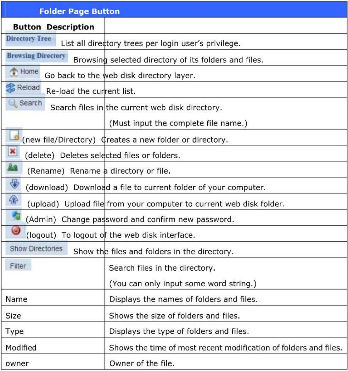 |
Photo Server (Does not apply to the 3X series' photo server)
Using the Photo Server, users can view and share photos, and even create their own albums right on the Thecus IP storage. You will see your own photo gallery and all public photo albums on the network. To manage any picture files, you must first select the item by clicking the box then entering your user name and password to log in to the photo server.  Windows XP Publishing Wizard
There are many ways for a local user to upload pictures into their photo album. Users of Windows XP can upload their pictures using the Windows XP Publishing Wizard. 1. Click on the XP Publishing Wizard icon on top right corner.  2. The XP Web Publishing Wizard Client screen appears. Click on the link to install the Publishing Wizard.  3. Windows XP will ask whether you want to run or save this file. Click Save to save the register file.  4. Once the register file is installed, use the Windows file manager to browse the folder that contains the picture you want to publish. On the left pane, there will be an icon labeled "Publish this folder to the Web".  5. Click on this icon and Web Publishing Wizard will start.  6. Select the pictures you want to publish to the Photo Web Server by placing a check mark on the top left hand corner of the picture. Click Next.  7. Your PC will start to connect to the Photo Web Server. 8. Select Thecus IP storage Photo Gallery Wizard to publish your pictures to Thecus IP storage.  9. Login into Thecus IP storage with your local user name and password.  10. Create your album by entering an album name and clicking on the Create Album button.  11. Select the album you want to upload your pictures to. 12. Confirm the target album.  13. Windows will show you that the picture upload is in progress.  14. When the upload is finished, the Wizard will ask you whether if you want to go to the website. Click Finish to go to your Photo Web Server.  15. Click on the user's icon to go to that user's album.  16. You will see the user's album list. Click on Album.  17. Finished! You will see the pictures just selected in the album. Managing Albums and Photos
Icon Function Description
 Make Cover Make selected photo your cover picture.  Back Return to the previous screen.  Add Add a new album or photos.  Modify Edit the name and description of the selected album or photo. Each name is limited to 20 characters and each description is limited to 255 characters.  Delete Delete the selected albums or photos.NOTE
- Only logged in users will see these icons. - To prevent system errors, Thecus IP storage sets the following limitations on photo files: - Each file upload is limited to a size of 8MB. Files exceeding 8MB will NOT be uploaded and no error message will appear. - Only these photo file types will be uploaded: \*.jpg, \*.gif, \*.bmp, \*.png, \*.pcx, \*.psd, \*.bmp. - If duplicate file names exist during upload process, system will add a number in front of the original file name (abc → 1abc).Creating Albums
To create a photo album, follow the steps below: 1. Click the Add button to create a new album. 2. Enter a name for the album, and enter a description if you wish. Then, click on the Create Album button.Password Protecting Albums
If you would like to put a password on a particular album, follow these steps: 1. Select the album to be protected, click on the Edit button, and the Album Edit screen will appear. 2. The owner of the album can enter an album password to protect the album, so that only people with the correct password can view the album.Uploading Pictures to Albums
Uploading pictures to albums using the Web User Interface is easy: 1. When the album is created, click the album icon to enter the album. Initially the album is empty. 2. Click the Add button to upload pictures into the album. The Upload Photos screen will appear. Users can select and upload up to 8 pictures at a time. 3. Once the picture is uploaded, you can view it in the album. The owner of the album can delete or modify the pictures with the Delete or Modify buttons on the top right hand cornerEXIF Information
While viewing pictures, you can also have Thecus IP storage display the EXIF information for each photo.  Simply click the EXIF button to display EXIF information. To hide this information, click the EXIF button again.Slide Shows
Slide shows are a great way to enjoy pictures stored on your Thecus IP storage. You can click on the Start Slide Show icon on the top right hand corner to start the slide show.  To stop the slide show, click on the Stop Slide Show icon on the top right hand corner.Mapping a Client PC to the Thecus IP Storage
You can map share folders on Thecus IP storage so that you can access them as if they were drives on your computer. You can connect to the shared network folders on Thecus IP storage as follows:Windows
1. Go to the My Computer folder in Windows. 2. In the menu bar, select Tools and then Map Network Drive... 3. The Map Network Drive window appears. 4. Assign a drive letter for the share folder. 5. Click the Browse button to find the folder over your network. Alternatively, you may enter the folder name you wish to connect to or enter its IP address. (i.e. \\192.168.1.100\share) 6. Click Finish. When the Connect As... window appears, enter your user name and password. 7. Click OK. The share folder appears as the drive you assigned. You can now access this folder as though it were a drive on your computer.Apple OS X
On an Apple computer, you can connect to shared computers and servers using a network address. 1. Choose Go > Connect to Server... 2. Enter the network address for the server in the Server Address text box. When connecting using SMB/CIFS protocol, type: smb://192.168.1.100/Folder1 When connecting using AFP protocol, type: afp://192.168.1.100/Folder1 Click Connect. 3. When MAC OS X is trying to connect Thecus IP storage, it will ask for a User Name and Password which has access to the folder. 4. When MAC OS X has connected to Thecus IP storage successfully, an icon representing the folder will appear on the MAC OS X desktop. You can access the folder by double clicking on the icon.Mapping Thecus IP storage as an iSCSI Drive
With Thecus IP storage, you are able to map it as an iSCSI drive. With iSCSI, you can remotely access Thecus IP storage at great speeds, as if it were installed as a local drive in your computer. To do this, simply follow the steps below:Windows 2000/XP
1. First, download the iSCSI Initiator from the Microsoft website (http://www.microsoft.com). You can find this software by entering iSCSI Initiator into the search box on their homepage. 2. Once the download is complete, install the iSCSI Initiator by double-clicking the EXE file. You may be presented with the following security warning. Click Run to continue.  3. You will now install the iSCSI Initiator using the Setup Wizard. Click Next to continue.  4. Leave the default selections and click Next.  5. Read the license agreement. To continue with the installation, click I Agree and then click Next.  6. The iSCSI Initiator will now install automatically. Click Finish once completed.  7. Start the iSCSI Initiator by double-clicking its icon on the desktop. The iSCSI Initiator properties window will appear.  Microsoft iSCSI Initiator 8. Select the Discovery tab. Under Target Portals, click Add.  9. Enter the IP address of Thecus IP storage. Click OK.  10. On the iSCSI Initiator Properties window, select the Targets tab. With the iSCSI target highlighted, click Log On. The Log On to Target dialogue will appear.  11. If you have not enabled CHAP, click OK to continue.  If you have enabled CHAP, click Advanced. Under Advanced Settings, check the CHAP login information checkbox and enter your username and password. Click OK.  12. Right click My Computer on the desktop and select Manage.  13. Click on Disk Management and you will see a new hard disk listed.  14. Initialize the new hard disk and you will then be able to use the iSCSI target as a local drive.Windows Vista
Because Windows Vista has the Microsoft iSCSI Initiator pre-installed, you will not have to install this piece of software. Instead, start the iSCSI Initiator and follow steps 8-14 to map the Thecus IP storage as an iSCSI drive.Chapter 6: Tips and Tricks
USB and eSATA Storage Expansion
The Thecus IP storage supports external USB hard disks through its USB ports. Once a USB hard disk has successfully mounted, the entire volume will be linked automatically to the default USB HDD folder. The Thecus IP storage supports USB external storage devices. All file names on the USB disk volume are case sensitive. The Thecus IP storage also supports eSATA hard disks with its eSATA port. Before attaching an eSATA or USB disk drive to Thecus IP storage, you have to partition and format it on a desktop computer or a notebook first. The attached device will be located at \\192.168.1.100\usbhdd\sd(x)1 where 192.168.1.100 means the IP address of Thecus IP storage and sd(x)1 stands for the first partition on the eSATA or USB disk drive.Adding a Spare Disk
With a RAID 1, RAID 5, RAID 6, or RAID 10 volume, you can add a spare disk after the initial RAID is setup. To add a spare disk, follow the steps below: 1. On the RAID Configuration Screen, tick the checkbox of the hard disk you wish to designate as a spare disk. 2. Click Add Spare. The disk will be configured as a spare disk. The system automatically rebuilds the spare disk when one of the disks in the RAID set fails.Remote Administration
You can set up your Thecus IP storage for remote administration. With remote administration, you can access your Thecus IP storage over the Internet, even if your Thecus IP storage is behind a router. This is especially useful if you are traveling and suddenly need a file from your Thecus IP storage. Setting up remote administration is a three-part process, and will require the following equipment: • Thecus IP storage device - Cable / DSL Router with Dynamic DNS support - Home PC - Internet ConnectionNOTE
Router setup will differ slightly depending on router used. For this example, we will use the Asus WL500g because it has support for Dynamic DNS. Contact your router hardware vendor for setup help.Part I - Setup a DynDNS Account
1. Go to http://www.dyndns.org from your home PC. 2. Click on the Sign Up Now link. 3. Check the Check boxes, select a user name (i.e.: N8800), enter your email address (i.e.: xxx@example.com), check Enable Wildcard, and create a password (i.e.: xxxx). 4. Wait for an email from www.dyndns.org. 5. Open the email and click on the link to activate your accountPart II - Enable DDNS on the Router
1. Go to the router setup screen and select IP Config > Miscellaneous DDNS Setting from your Home PC. 2. Click on Yes for Enable the DDNS Client? 3. Select www.dyndns.org. 4. Go to router setup screen, and enter the following information: a. User Name or E-mail Address: xxx@example.com b. Password or DDNS Key: xxxx c. Host Name: www.N8800.dyndns.org d. Enable wildcard? Select Yes e. Update Manually: Click UpdatePart III - Setting up Virtual Servers (HTTPS)
1. Navigate to NAT Setting > Virtual Server. 2. For Enable Virtual Server?, select Yes 3. Setup the HTTPS Server a. Well-Known Applications: Select User Defined b. Local IP: Enter 192.168.1.100 c. Port Range: 443 (the default HTTPS port setting on the Thecus IP storage) d. Protocol: select TCP e. Click Add. f. Click Apply. 4. Test the HTTPS connection from another computer on the Internet a. From a remote computer, open your browser and enter https://www.N8800.dyndns.org b. You should see the login page of N8800.Firewall Software Configuration
If you are using a software firewall (i.e. Norton Internet Security) and are having trouble connecting to Thecus IP storage, you can try the following steps: 1. Double click the NIS icon on system tray, and then configure the Personal Firewall. 2. On the Programs page, find the SetupWizard.exe and change its permission to "Permit All". If it's not in the program list, use the Add or Program Scan buttons to find it. 3. On the Networking page, manually add N8800 IP address (i.e. 192.168.1.100) to the Trusted list.Replacing Damaged Hard Drives
If you are using RAID 1, RAID 5, or RAID 6 you can easily replace a damaged hard drive in the Thecus IP storage while keeping your data secure with the system's automatic data recovery.Hard Drive Damage
When a hard drive is damaged and data in the RAID volume, the system LCD will display warning message also the system beeps.Replacing a Hard Drive
To replace a hard disk drive in Thecus IP storage: 1. Remove the tray with the damaged hard disk (N3200XXX/N0503 is using HDD rail). 2. Unscrew the damaged hard disk and remove it from the tray. 3. Slide a new hard disk into the tray and fasten the screws. 4. Insert the hard disk tray back into Thecus IP storage until it snaps into place. You can also lock it with a key if desired. 5. The LED blinks green when the HDD is accessed.RAID Auto-Rebuild
When using RAID 1, 5, 6, or 10 on Thecus IP storage, you can use the auto-rebuild function when an error is detected. 1. When a hard disk fails the system beeps and/or an email notification is sent to specified receivers. 2. Check the LCD to see which disk has failed. 3. Follow the steps mentioned above to replace the failed hard disk. 4. The system automatically recognizes the new hard disk and starts the auto-rebuild sequence to resume its status before the hard disk crash.Chapter 7: Troubleshooting
Forgot My Network IP Address
If you forget your network IP address and have no physical access to the system, you can find out the IP address by either looking directly onto Thecus IP storage LCD panel, or by using the setup wizard to retrieve the IP of your Thecus IP storage. 1. Start the Setup Wizard, and it will automatically detect all Thecus IP storage products on your network. 2. You should be able to find the IP address of Thecus IP storage which you have forgotten in the Device Discovery screen.Can't Map a Network Drive in Windows XP
You may have problems mapping a network drive under the following conditions: 1. The network folder is currently mapped using a different user name and password. To connect using a different user name and password, first disconnect any existing mappings to this network share. 2. The mapped network drive could not be created because the following error has occurred: Multiple connections to a server or shared resource by the same user, using more than one user name, are not allowed. Disconnect all previous connections to the server or shared resource and try again. To check out existing network connections, type net use under the DOS prompt. You may refer the URL below for more network mapping information. http://esupport.thecus.com/support/index.php?\_m=downloads&\_a=viewdownload&downloaditemid=57&nav=0Restoring Factory Defaults
From the System menu, choose the Factory Default item and the Reset to Factory Default screen appears. Press Apply to reset Thecus IP storagefactory default settings. WARNING Resetting to factory defaults will not erase the data stored in the hardProblems with Time and Date Settings
The administrator is able to select an NTP Server to keep Thecus IP storage time synchronized. However, if Thecus IP storage can not access the Internet, you may encounter a problem when setting the Time and Time Zone. If this happens: 1. Login to the Web Administration Interface. 2. Navigate to System Management>Time. 3. Under NTP Server, select No. 4. Set the Date, Time, and Time Zone. 5. Click Apply. In addition, if Thecus IP storage is able to access the Internet and you want to keep the NTP Server clock.isc.org by default, please make sure the DNS Server is correctly entered, thereby allowing the NTP Server name to correctly resolve. (See System Network > WAN/LAN1 > DNS Server)Dual DOM Supports for Dual Protection
The most advance and useful of Thecus IP storage (depend on models) is Dual DOM implemented. In the normal circumstance, it has no need to have this feature involved. But with irresistible cause like power cut or human error by accident occurred especially during system booting stage, this will become the great feature to prevent system down time. Practically while it happened, system will try to recovery the DOM 1 from DOM 2 first. If it is unachievable then system can boot from DOM 2. And all of this procedure can be operated by LCM.NOTE
The Dual DOM in DOM1 is default master and FW upgrading will only execute in DOM1 unlike DOM2 is 'Read only' initially. Any circumstance occurred, while DOM2 successes recover DOM1. The FW will be version of DOM2. Therefore, it may need to upgrade to the version of DOM1 it has. If DOM1 can not be recovery from DOM2, then system will boot up from DOM2. The original configuration in DOM1 may need to setup again with DOM2 operation.Appendix A: Customer Support
If your Thecus IP storage is not working properly, we encourage you to check out Chapter 7: Troubleshooting, located in this manual. You can also try to ensure that you are using the latest firmware version for your Thecus IP storage. Thecus is committed to providing free firmware upgrades to our customers. Our newest firmware is available on our Download Center: http://www.thecus.com/download.php If you are still experiencing problems with your Thecus IP storage, or require a Return Merchandise Authorization (RMA), feel free to contact technical support via our Technical Support Website: http://www.thecus.com/support\_tech.php Customers in the US should send all technical support enquiries to the US contact window included in the following web page: http://www.thecus.com/support\_tech.php For Sales Information you can e-mail us at: sales@thecus.comThank you for choosing Thecus!
Appendix B: RAID Basics
Overview
A Redundant Array of Independent Disks (RAID) is an array of several hard disks that provide data security and high performance. A RAID system accesses several hard disks simultaneously, which improves I/O performance over a single hard disk. Data security is enhanced by a RAID, since data loss due to a hard disk failure is minimized by regenerating redundant data from the other RAID hard disks.Benefits
RAID improves I/O performance, and increases data security through fault tolerance and redundant data storage.Improved Performance
RAID provides access to several hard disk drives simultaneously, which greatly increases I/O performance.Data Security
Hard disk drive failure unfortunately is a common occurrence. A RAID helps prevent against the loss of data due to hard disk failure. A RAID offers additional hard disk drives that can avert data loss from a hard disk drive failure. If a hard drive fails, the RAID volume can regenerate data from the data and parity stored on its other hard disk drives.RAID Levels
The Thecus IP storage supports standard RAID levels 0, 1, 5, 6, 10, and JBOD. You choose a RAID level when you create a system volume. The factors for selecting a RAID level are: - Your requirements for performance - Your need for data security - Number of hard disk drives in the system, capacity of hard disk drives in the system The following is a description of each RAID level:RAID 0
RAID 0 is best suited for applications that need high bandwidth but do not require a high level of data security. The RAID 0 level provides the best performance of all the RAID levels, but it does not provide data redundancy. RAID 0 uses disk striping and breaking up data into blocks to write across all hard drives in the volume. The system can then use multiple hard drives for faster read and write. The stripe size parameter that was set when the RAID was created determines the size of each block. No parity calculations complicate the write operation.RAID 1
RAID 1 mirrors all data from one hard disk drive to a second one hard disk drive, thus providing complete data redundancy. However, the cost of data storage capacity is doubled. This is excellent for complete data security.RAID 5
RAID 5 offers data security and it is best suited for networks that perform many small I/O transactions at the same time, as well as applications that require data security such as office automation and online customer service. Use it also for applications with high read requests but low write requests. RAID 5 includes disk striping at the byte level and parity information is written to several hard disk drives. If a hard disk fails the system uses parity stored on each of the other hard disks to recreate all missing information.RAID 6
RAID 6 is essentially an extension of RAID level 5 which allows for additional fault tolerance by using a second independent distributed parity scheme (dual parity). Data is striped on a block level across a set of drives, just like in RAID 5, and a second set of parity is calculated and written across all the drives; RAID 6 provides for an extremely high data fault tolerance and can sustain two simultaneous drive failures. This is a perfect solution for mission critical applications.RAID 10
RAID 10 is implemented as a striped array whose segments are RAID 1 arrays. RAID 10 has the same fault tolerance as RAID level 1. RAID 10 has the same overhead for fault-tolerance as mirroring alone. High I/O rates are achieved by striping RAID 1 segments. Under certain circumstances, RAID 10 array can sustain up to 2 simultaneous drive failures Excellent solution for applications that would have otherwise gone with RAID 1 but need an additional performance boost.JBOD
Although a concatenation of disks (also called JBOD, or "Just a Bunch of Disks") is not one of the numbered RAID levels, it is a popular method for combining multiple physical disk drives into a single virtual one. As the name implies, disks are merely concatenated together, end to beginning, so they appear to be a single large disk. As the data on JBOD is not protected, one drive failure could result total data loss.Stripe Size
The length of the data segments being written across multiple hard disks. Data is written in stripes across the multiple hard disks of a RAID. Since multiple disks are accessed at the same time, disk striping enhances performance. The stripes can vary in size.Disk Usage
When all disks are of the same size, and used in RAID, Thecus IP storage disk usage percentage is listed below:| RAID Level Percentage Used | |
| RAID 0 100% | |
| RAID 1 1/n x 100% | |
| RAID 5 (n-1)/n x 100% | |
| RAID 6 (n-2)/n x 100% | |
| RAID 10 50% | |
| JBOD 100% |