XAVB2602 - Power adapter NETGEAR - Free user manual and instructions
Find the device manual for free XAVB2602 NETGEAR in PDF.

User questions about XAVB2602 NETGEAR
0 question about this device. Answer the ones you know or ask your own.
Ask a new question about this device
Download the instructions for your Power adapter in PDF format for free! Find your manual XAVB2602 - NETGEAR and take your electronic device back in hand. On this page are published all the documents necessary for the use of your device. XAVB2602 by NETGEAR.
USER MANUAL XAVB2602 NETGEAR
natural_image
Abstract geometric composition with overlapping colored triangles (no text or symbols)Powerline PassThru Adapter
Support
Thank you for purchasing this NETGEAR product.
After installing your device, locate the serial number on the label of your product and use it to register your product at https://my.netgear.com. You must register your product before you can use NETGEAR telephone support. NETGEAR recommends registering your product through the NETGEAR website. For product updates, additional documentation, and support, visit http://support.netgear.com.
Phone (US & Canada only): 1-888-NETGEAR.
Phone (Other Countries): Check the list of phone numbers at http://support.netgear.com/general/contact/default.aspx.
Trademarks
NETGEAR, the NETGEAR logo, and Connect with Innovation are trademarks and/or registered trademarks of NETGEAR, Inc. and/or its subsidiaries in the United States and/or other countries. Information is subject to change without notice. © NETGEAR, Inc. All rights reserved.
Contents
Chapter 1 Getting Started
Hardware Features....6
XAV2602 Powerline 200 Nano PassThru Two-Port Adapter .....6
XAV5401 Powerline 500 PassThru One-Port Adapter....7
XAV5602 Powerline 500 Nano PassThru Two-Port Adapter .....8
XAV6501 Powerline 600 PassThru One-Port Adapter....9
XAV6504 Powerline 600 PassThru Four-Port Adapter .....10
LED Descriptions ..... 11
Button Descriptions 11
Ethernet Port 11
Filtered AC Socket 12
Product Label 12
How the Powerline PassThru Adapter Fits into Your Network .....12
Set Up the Powerline Network .....14
Set Up a New Powerline Network .....14
Add the Adapter to an Existing Powerline Network .....15
Powerline Network Security 16
Use the Security Button to Set the Encryption Key .....16
Chapter 2 Using NETGEAR genie
Install NETGEAR genie ....19
Powerline Map....20
Security Icon....21
View the Link Rate Between Powerline Devices .....22
Change the Name of a Powerline Device....23
Turn LEDs Off or On. 24
Set the Powerline Encryption Key 24
Reset a Device to Factory Default Settings .....26
Add a Device to the Powerline Network 27
Chapter 3 Troubleshooting
Basic Functioning ....30
Troubleshooting Buttons. 30
Troubleshooting LEDs 30
LEDs Are Off When the Powerline Device Is Plugged In . . . . . . . . . . . . . . . . . . 30
Power LED 30
Powerline LED 31
Ethernet LED Is Off 31
If You Do Not See All Your Devices with the NETGEAR genie . . . . . . . .32
Powerline PassThru Adapter
If You Do Not See the Powerline Icon on Your Network Map .....32
Symantec Endpoint Protection....32
Appendix A Supplemental Information
XAV2602 Technical Specifications....37
XAV5401 Technical Specifications....38
XAV5602 Technical Specifications....39
XAV6501 Technical Specifications....40
XAV6504 Technical Specifications....41
Safety Information 42
Appendix B Notification of Compliance
This chapter describes your Powerline PassThru adapter and how your adapter fits into a home network. It also explains the security features and how to secure your Powerline network with a private encryption key.
This chapter includes the following sections:
- Hardware Features
• How the Powerline PassThru Adapter Fits into Your Network - Set Up the Powerline Network
• Powerline Network Security - Use the Security Button to Set the Encryption Key
For more information about the topics covered in this manual, visit the NETGEAR support website at http://support.netgear.com.
Hardware Features
This section describes the hardware features of the Powerline PassThru adapters. Adapters vary by region. Your adapter might look different.
XAV2602 Powerline 200 Nano PassThru Two-Port Adapter
The hardware features of the XAV2602 adapter are shown in the following figure.
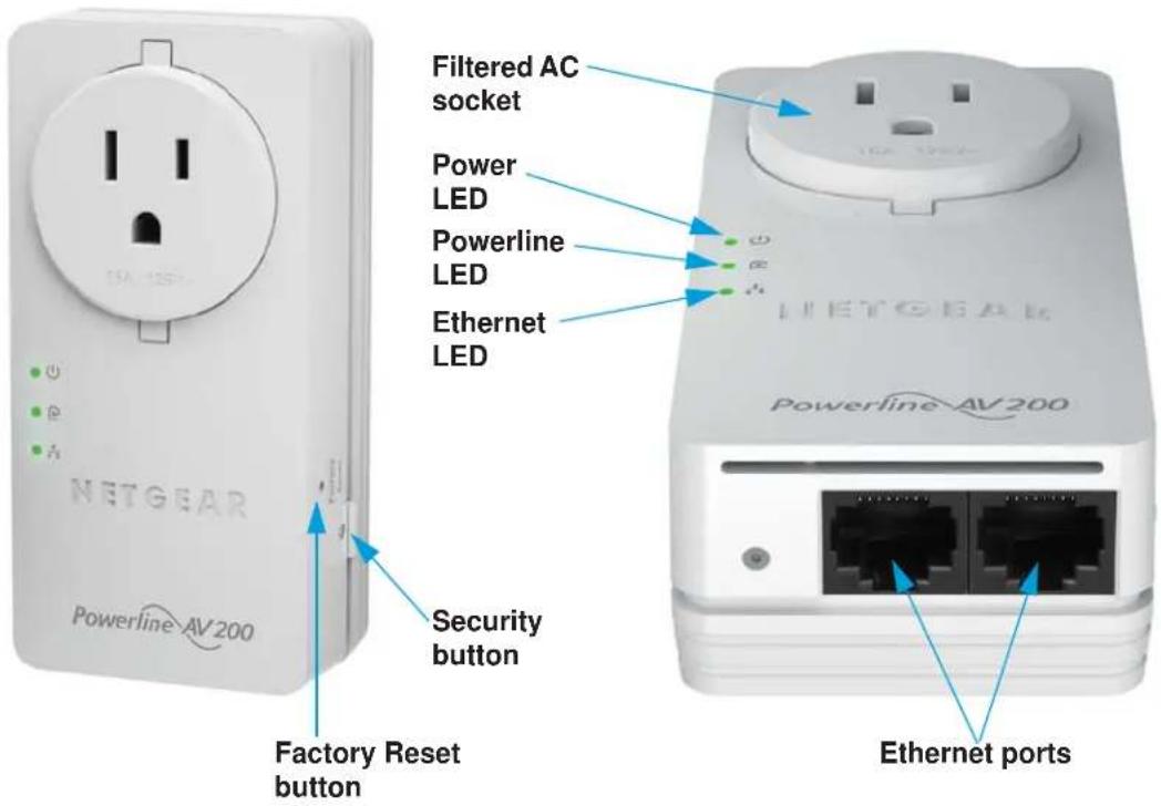
Figure 1. XAV2602 hardware features
XAV5401 Powerline 500 PassThru One-Port Adapter
The hardware features of the XAV5401 adapter are shown in the following figure.
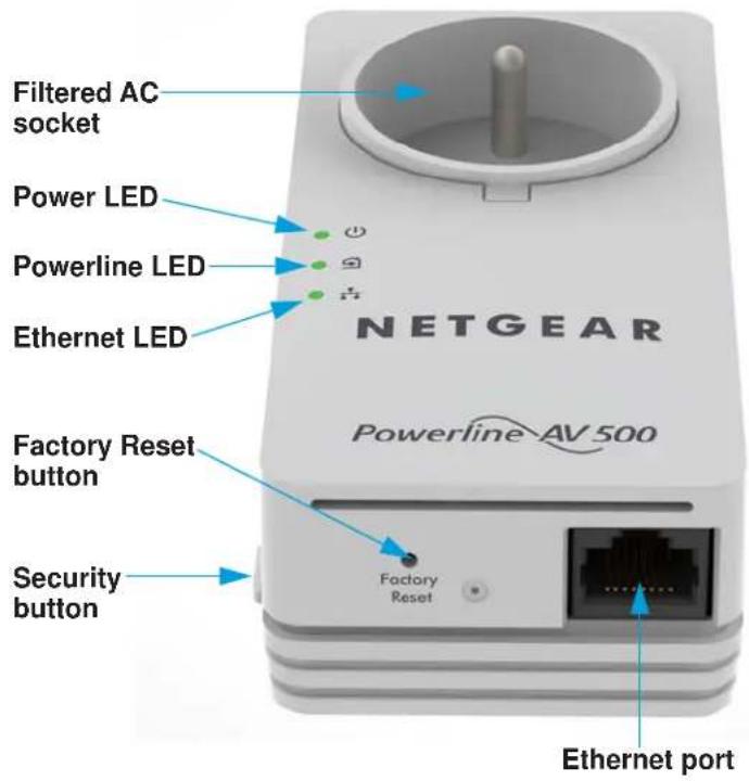
Figure 2. XAV5401 hardware features
XAV5602 Powerline 500 Nano PassThru Two-Port Adapter
The hardware features of the XAV5602 adapter are shown in the following figure.
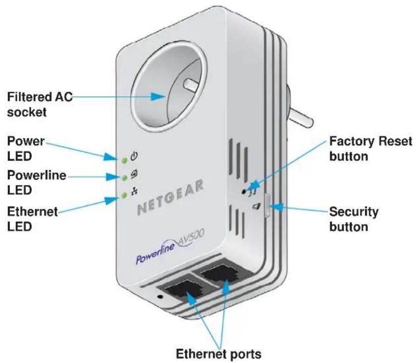
Figure 3. XAV5602 hardware features
XAV6501 Powerline 600 PassThru One-Port Adapter
The hardware features of the XAV6501 adapter are shown in the following figure.
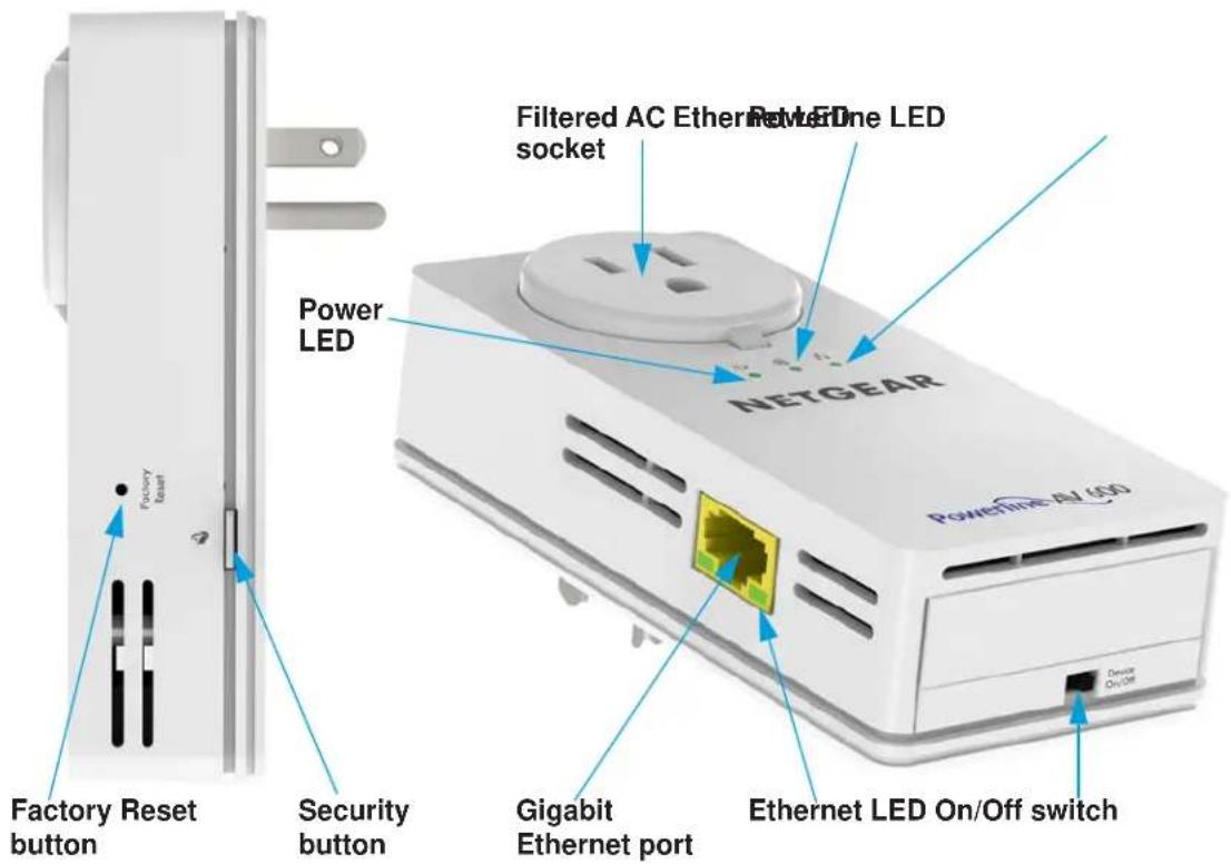
Figure 4. XAV6501 hardware features
XAV6504 Powerline 600 PassThru Four-Port Adapter
The hardware features of the XAV6504 adapter are shown in the following figure.
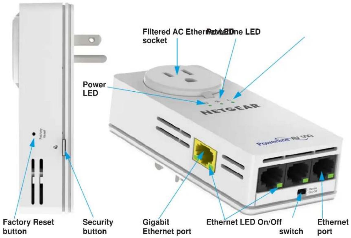
Figure 5. XAV6504 hardware features
LED Descriptions
The LEDs indicate the status of your Powerline adapter.
Table 1. LED descriptions
| Item Description | |||
Power LED | Solid green. The electrical power is on.Blinking green. The adapter is setting up security.Amber. The adapter is in power saving mode. If the Ethernet port is inactive for more than ten minutes, the adapter enters power saving mode.Off. The adapter does not have electrical power or the LEDs were off using NETGEAR genie. | ||
Powerline LED | Solid. The adapter is connected to a Powerline network.Off. The adapter has not found any other compatible Powerline devices using the same encryption key. | ||
| The Pick A Plug feature lets you pick the electrical outlet with the fastest link rate, indicated by the color of the LED: | |||
| Green. Link rate > 80 Mbps (Fast) | Amber. Link rate > 50 and < 80 Mbps (Medium) | Red. Link rate < 50 Mbps (Slow) | |
Ethernet LED | Solid green. The Powerline adapter is connected through the Ethernet port to a powered-on Ethernet device.Off. There is no Ethernet connection. | ||
Button Descriptions
Use the buttons on your Powerline adapter to do the following:
- Factory Reset button. Use the Factory Reset button to return your Powerline PassThru adapter to its factory default settings. Press the Factory Reset button for two seconds and release it.
- Security button. After the Powerline adapters are active, you can use the Security button to secure your Powerline network with a private encryption key. See Use the Security Button to Set the Encryption Key on page 16.
- Power On/Off switch. Use the Power On/Of f switch to turn the device on and off. When this switch is in the Off position, the filtered AC socket still has power.
Ethernet Port
Powerline adapters use an Ethernet port to convert a standard electrical wall outlet into a high-speed wired network connection. You can use the wired network connection to bring Internet connectivity to any device with an Ethernet port, such as a computer, game console, Blu-ray player, smart TV, HD set-top box, or network DVR.
Filtered AC Socket
The filtered AC socket can remove some electrical noise that might affect Powerline performance. Plugging the power plugs of nearby devices into the filtered AC socket improves performance.
Product Label
The product label provides unique details specific to your device, including the following information:
- Model number
• Powerline MAC address - Ethernet MAC address
- Serial number
- Device password
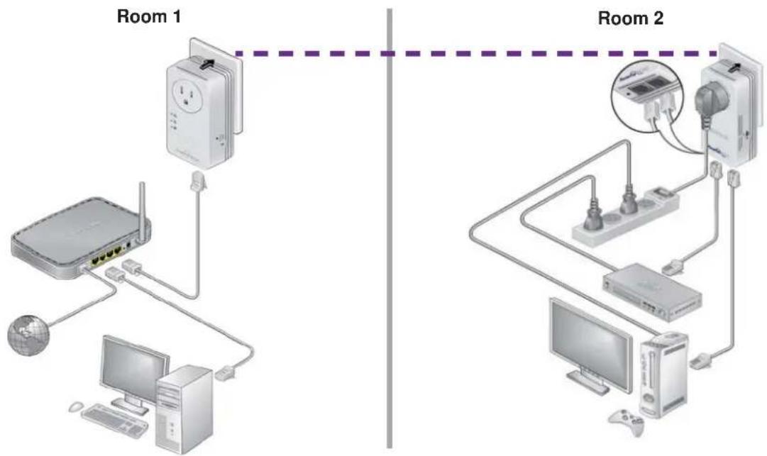
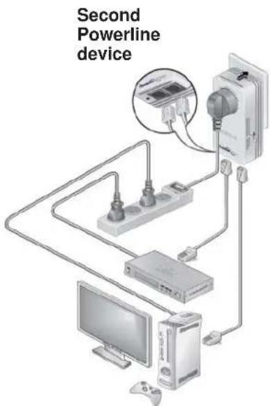
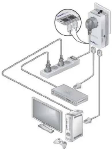
How the Powerline PassThru Adapter Fits into Your Network
You can use one or more Powerline adapters to extend Internet access throughout your home.
A Powerline network consists of two or more compatible Powerline devices that communicate with each other using your electrical power lines. One of the Powerline devices is connected with an Ethernet cable to your router so that the Powerline network is linked to your local area network (LAN). Connecting one Powerline device to your router allows all the Powerline devices on the Powerline network to communicate with the router and use its Internet connection.
The following illustration shows a Powerline network with one Powerline device in Room 1 and a second Powerline device in Room 2.
flowchart
graph TD
    subgraph Room 1
        A["Router"] --> B["Server"]
        C["Desktop Computer"] --> D["Wireless Device"]
        E["Global Network"] --> D
        D --> F["Computer"]
        G["Router"] --> H["Server"]
        I["Desktop Computer"] --> J["Wireless Device"]
        K["Global Network"] --> L["Computer"]
    end
    subgraph Room 2
        M["Router"] --> N["Server"]
        O["Desktop Computer"] --> P["Wireless Device"]
        Q["Global Network"] --> R["Computer"]
        S["Digital Display"] --> T["Switch"]
        U["Switch"] --> V["Switch"]
        W["Switch"] --> X["Switch"]
        Y["Switch"] --> Z["Switch"]
        AA["Switch"] --> AB["Switch"]
        AC["Switch"] --> AD["Switch"]
        AE["Switch"] --> AF["Switch"]
        AG["Switch"] --> AH["Switch"]
    end
Figure 6. A Powerline network with two Powerline PassThru adapters
To form a Powerline network, you need at least two compatible Powerline devices.
For best performance, follow these guidelines when you plan the location of your Powerline devices:
- Use an electrical outlet that is not controlled by a wall switch to avoid accidentally turning off the power to the outlet.
- A void plugging Powerline products into electrical outlets that are located near appliances that consume a lot of power, such as washers, dryers, or refrigerators. Interference from these appliances might prevent Powerline products from working correctly or reduce Powerline network performance.
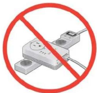
- Do not plug Powerline products into a power strip, extension cord, or surge protector. Connecting a Powerline product to one of these devices might prevent the product from working correctly or reduce Powerline network performance.
Set Up the Powerline Network
You can set up a new Powerline network that includes the Powerline PassThru adapter or you can add the Powerline PassThru adapter to an existing Powerline network.
Set Up a New Powerline Network
Different Powerline models can share the same Powerline network. All NETGEAR Powerline AV products are compatible.
To set up a new Powerline network:
- Make sure that your wired Ethernet connections are working:
a. If you have an existing wireless network, make sure that it is connected to the Internet.
b. On a computer that is connected to your router or gateway using an Ethernet cable, open a web browser and navigate to a web page.
c. On a computer or device that is connected to your wireless network, open a web browser and navigate to a web page.
-
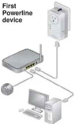
Plug the one Powerline device into a wall outlet near your router or gateway.
-
Connect the device to the LAN port on your router or gateway using an Ethernet cable.
-
Plug the second Powerline device into a wall outlet where you want to add Internet access.
-
(Optional) Use the Ethernet cable that came with your adapter to connect the Powerline device to an Ethernet port on a computer, game console, Blu-ray player, or other peripheral device.
The Powerline devices attempt to detect each other and form a Powerline network.
- Wait for the Powerline network to recognize each Powerline device.
This process could take as little as 5 seconds or up to 80 seconds.
When the Power and Powerline LEDs stop blinking, the process is complete. If the Powerline LEDs are green or amber, the devices are successfully connected to the Powerline network. A red Powerline LED indicates a slow link rate. In this case, move the Powerline device to another electrical outlet with a faster connection.
- Secure your Powerline network.
See Use the Security Button to Set the Encryption Key on page 16.
Add the Adapter to an Existing Powerline Network
If you have an existing Powerline network, make sure that one of the Powerline devices is connected to your router or gateway so that the Powerline network is linked to your local area network (LAN). Your Powerline network must have two or more compatible Powerline devices that communicate with each other.
To add the Powerline PassThru adapter to a Powerline network:
- If you used the Security buttons or NETGEAR genie to secure your Powerline network, press the Factory Reset button for two seconds on each Powerline device to return it to its factory default settings.
This method is the quickest way to allow your Powerline PassThru adapter to communicate with the other Powerline devices.
- Plug the Powerline PassThru adapter into a wall outlet where you want to add Internet access.
- (Optional) Use the Ethernet cable that came with your adapter to connect the adapter to an Ethernet port on a computer, game console, Blu-ray player, or other peripheral device.
The Powerline devices attempt to detect each other and form a Powerline network.
- Wait for the Powerline network to recognize each Powerline device.
This process could take as little as 5 seconds or up to 80 seconds.
When the Power and Powerline LEDs stop blinking, the process is complete. If the Powerline LEDs are green or amber, the devices are successfully connected to the Powerline network. A red Powerline
LED indicates a slow link rate. In this case, move the Powerline device to another electrical outlet with a faster connection.
natural_image
Diagram of a network device setup with monitor, tower, keyboard, and server connected to a device (no text or labels visible)- Secure your Powerline network.
See Use the Security Button to Set the Encryption Key on page 16.
Powerline Network Security
A Powerline network consists of two or more Powerline devices using the same network encryption key. Securing your network is crucial. By encrypting the information that you send over the Powerline network, you help to keep it secure from hackers. If you do not set up security on your network, anyone nearby with a Powerline network can potentially use his or her connection to gain access to your network and information that you send over the Internet. This concern is especially relevant in settings such as apartment buildings, office buildings, dorm rooms, and other more populated areas.
You can use either the Security button on the Powerline device or NETGEAR genie to secure your Powerline network:
- Use the Security button on the Powerline device to automatically generate a random private encryption key. See Use the Security Button to Set the Encryption Key on page 16.
- Use NETGEAR genie to configure your Powerline network with a private encryption key that you specify. See Chapter 2, Using NETGEAR genie.
Use the Security Button to Set the Encryption Key
Note: A Powerline device can generate a random private encryption key only once. If you want to generate a new random key, first reset the Powerline devices to their factory default settings. Either press the Factory Reset button for two seconds, then release it, or use the NETGEAR genie factory reset feature. (See Reset a Device to Factory Default Settings on page 26.)
You can use the Security button to replace the default encryption key with a random private encryption key. The default encryption key is HomePlugAV.
To set the encryption key:
- Make sure that all of the Powerline devices that you want to configure are plugged in by checking that the Power and Powerline LEDs on each device are lit solid green.

CAUTION:
Do not press the Security button on the Powerline devices until the Power and Powerline LEDs on each Powerline device are lit solid green. Pressing the Security button too soon can temporarily disable Powerline communication. If Powerline communication is disabled, reset the Powerline device to its factory default settings by pressing the Factory Reset button for two seconds, then releasing it.
Powerline PassThru Adapter
- Press the Security button on the first Powerline device for two seconds.
The Power LED starts blinking after you release the button. then the Powerline device automatically creates a new, randomly generated encryption key that all other Powerline devices on the network will use.
At this point, the Powerline devices cannot communicate with each other.
- Within two minutes of pressing the Security button on the first Powerline device, press the Security button on the second Powerline device for two seconds.
You must press both Security buttons within two minutes.
The Power LED starts blinking after you release the button. This process allows the second Powerline device to use the same private encryption key as the first device so that they can communicate.
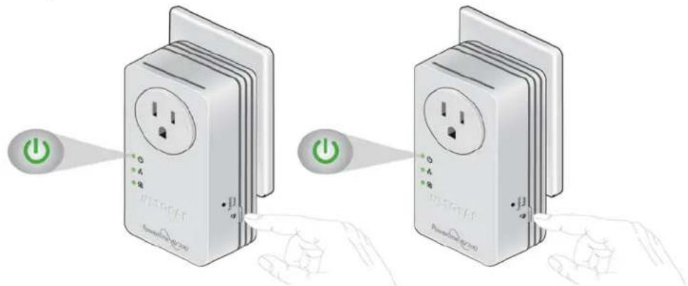
When the Power LEDs stop blinking and the Powerline LEDs are lit solid green, the two devices can communicate over the Powerline network in a secure way.

Note: This process works for only one pair of Powerline devices at a time. If you have more than two Powerline devices, repeat this process for each additional Powerline device to be configured. The devices retain security settings even if they are unplugged.
This chapter explains how to install NETGEAR genie and use it to manage your Powerline network. NETGEAR genie works with all Powerline devices.
You can use NETGEAR genie to manage a local Powerline device that is connected to your computer with an Ethernet cable and also to manage other Powerline devices on the same network.
This chapter includes the following sections:
• Install NETGEAR genie
- Powerline Map
• View the Link Rate Between Powerline Devices
- Change the Name of a Powerline Device
- Turn LEDs Off or On
- Set the Powerline Encryption Key
- Reset a Device to Factory Default Settings
- Add a Device to the Powerline Network
Install NETGEAR genie
NETGEAR genie allows you to set a private encryption key for your Powerline network and manage devices on your Powerline network.
You can manage the Powerline network using any computer that is connected to your Powerline network. You can manage all devices on a Powerline network from one computer.
Note: If NETGEAR genie is already installed on your computer, you must reinstall the latest version to get support for Powerline products.
NETGEAR genie is a free download available from the NETGEAR website.
To install NETGEAR genie on your computer:
- Launch an Internet browser and visit www.netgear.com/genie.

- Download the version of NETGEAR genie that corresponds to your operating system.
- Run the file that you downloaded and follow the setup prompts to install NETGEAR genie.
- Click the Finish button to complete the setup.
The NETGEAR genie shortcut icon displays on your desktop.

NETGEAR genie is installed on your computer.
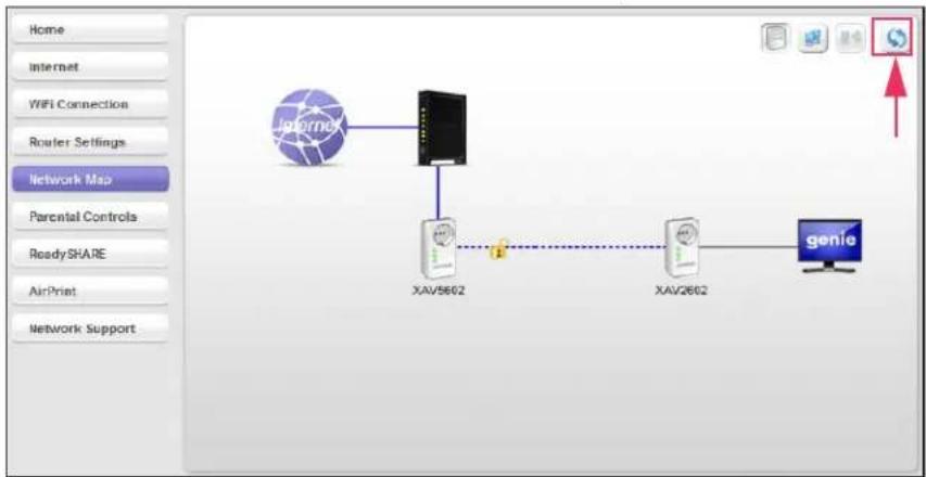
Powerline Map
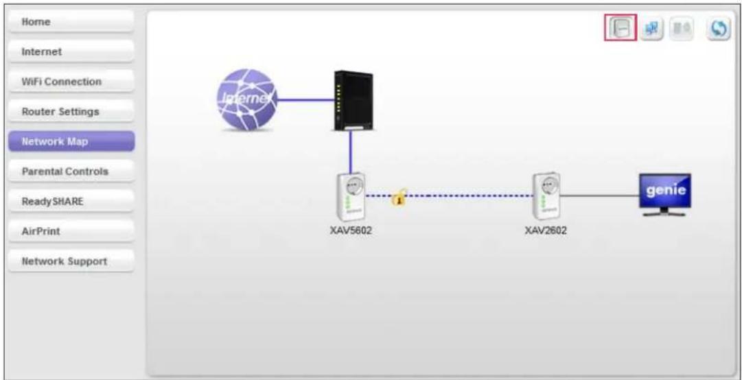
You can use genie's Powerline map to view and manage your Powerline network.
To navigate to the Powerline map:
- On a computer that is connected to your Powerline network, launch NETGEAR genie.
- From the NETGEAR genie Home screen, click Network Map on the dashboard.
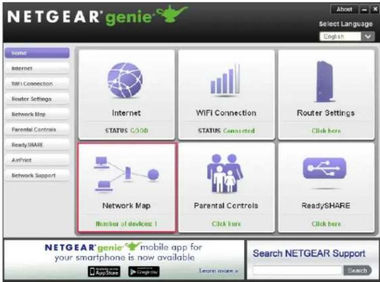
The Network Map screen displays.
3. Click the Powerline icon.
The Powerline map displays.
flowchart
graph TD
    A["Internet"] --> B["XAV5602"]
    B --> C["XAV2602"]
    C --> D["genie"]
    style A fill:#f9f,stroke:#333
    style B fill:#ccf,stroke:#333
    style C fill:#cfc,stroke:#333
    style D fill:#fcc,stroke:#333
Powerline PassThru Adapter
- To view management options, right-click the icon of the device that you want to manage. If all devices are not shown, click the Refresh icon to update the screen.
- T o view more information about a device, move your cursor over a device icon.
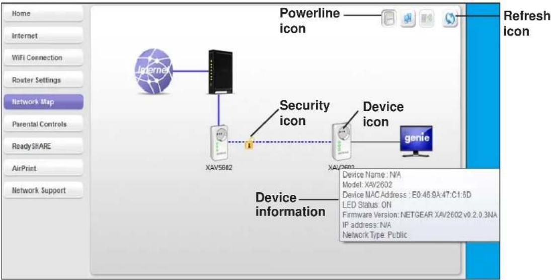
Security Icon
Click the Security icon on the Powerline map to go to the Security screen.
- If the Powerline devices are secured using the default encryption key, the unlocked Security icon displays.
- If the Powerline devices are secured using a private encryption key, the locked Security icon displays.
For more information about setting the encryption key, see Set the Powerline Encryption Key on page 24.


View the Link Rate Between Powerline Devices
To view the link rate between your Powerline devices:
On the Powerline map, click the icon of the device whose link rate you want to view.
A pop-up screen displays.
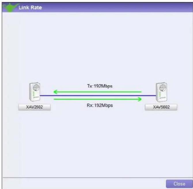
Tx indicates the rate at which the device is transmitting data. Rx indicates the rate at which the device is receiving data.
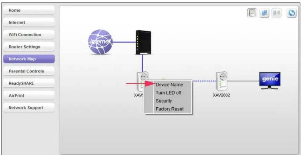
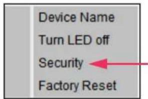
Change the Name of a Powerline Device
Powerline devices are identified by their model number and name. NETGEAR genie detects any Powerline devices that are connected to the Powerline network and displays them on the Powerline map. If you did not name the device, no name displays below the model number of the device.
To name a Powerline device on your Powerline network:
- On the Powerline map, right-click the icon of the device that you want to name.
- On the pop-up menu that displays, select Device Name.
flowchart
graph TD
    A["Internet"] --> B["Device Name"]
    B --> C["XAV1"]
    C --> D["XAV2602"]
    D --> E["genie"]
    style A fill:#f9f,stroke:#333
    style B fill:#ccf,stroke:#333
    style C fill:#cfc,stroke:#333
    style D fill:#fcc,stroke:#333
    style E fill:#cff,stroke:#333
A pop-up screen displays advising you that connectivity will be temporarily lost while the device is being renamed.
3. Click the OK button.
The following screen displays:

- Enter a new name for the Powerline device and click the OK button.
Your changes are saved.
Turn LEDs Off or On
You can turn off or turn on the LEDs of any device on your Powerline network.
To turn the LEDs off or on:
-
On the Powerline map, right-click the icon of the device.
-
On the pop-up menu that displays, select either T urn LED off or Turn LED on.
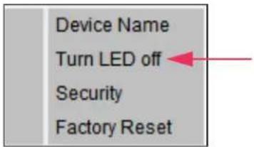
A pop-up screen displays advising you that connectivity will be temporarily lost while the LEDs are being reset.
- Click the OK button.
A message displays indicating that the operation was successful.

- Click the OK button.
Set the Powerline Encryption Key
Powerline devices on the same Powerline network use the same encryption key. The factory default encryption key is HomePlugAV.
In locations such as apartment buildings or office buildings, other people might use the same electrical power lines that you use for your Powerline network. To protect your Powerline network from unwanted access, you can use NETGEAR genie to set a private encryption key for your Powerline devices. Make sure that all of your Powerline devices use the same encryption key so that they can communicate with each other.
If you forget your private encryption key, you can reset the encryption key to the factory default key, HomePlugAV. See Reset a Device to Factory Default Settings on page 26.
To set the encryption key:
-
On the Powerline map, right-click the icon of a Powerline device in your network.
-
On the pop-up menu that displays, select Security.
The Security screen displays.
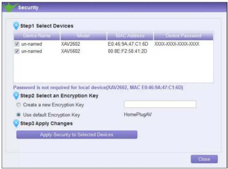
The top section of the Security screen shows information about each device that NETGEAR genie detects:
• Device Name. The list of Powerline devices that NETGEAR genie detects after completing a device scan. The device name is listed as un-named by default, but you can change it to a descriptive name, such as Office or Master Bedroom. (See Change the Name of a Powerline Device on page 23.)
- Model. The model number of the Powerline device.
- MAC Address. The MAC address of the Powerline device. This information is on the product label, which might not be visible when the device is plugged in.
- Device Password. If your computer is not connected locally (with an Ethernet cable) to the device that you want to configure, you must enter the device password. The device password is on the product label.
- Select the check box next to each device that you want to configure.
- Select an encryption key option for your Powerline devices:
- Create a new Encryption Key. To set your own private encryption key, type the key that you want to use in the field.
- Use default Encryption Key. When you select this radio button, the factory default encryption key automatically displays in the field. The factory default encryption key is HomePlugAV.
Note: If your computer is not connected locally (with an Ethernet cable) to the device that you want to configure, you must enter the device password. The device password is printed on the product label.
- Click the Apply Security to Selected Devices button.
When the encryption key is set, a message displays indicating that the operation was successful.
- Click the OK button.
Reset a Device to Factory Default Settings
You can reset the encryption key of a Powerline device to the factory default key, HomePlugAV.
Note: If your Powerline network uses a private encryption key, resetting a Powerline device to its factory default settings disconnects the device from the network. To avoid disconnecting your computer from the network, reset all other Powerline devices on the network before you reset the device that is connected to your computer.
To reset a device to its factory default settings:
- On the Powerline map, right-click the icon of the device that you want to reset.
- On the pop-up menu that displays, select Factory Reset.
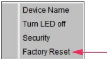
A pop-up screen displays advising you that connectivity will be temporarily lost while the device is being reset.
- Click the OK button.
A message displays asking you to confirm the reset.
- Click the OK button.
A message indicates whether the operation succeeded.
Add a Device to the Powerline Network
If you are adding a device to your Powerline network and your network uses the default encryption key, plug the new device into a power outlet.
If your Powerline network uses a private encryption key, you can set the security in one of two ways:
- Use the Security button to add the new device to your network. See Use the Security Button to Set the Encryption Key on page 16.
- Use NETGEAR genie to add the new device to your network, as described in the following procedure.
To add a Powerline device to the Powerline network using NETGEAR genie:
- Plug the Powerline device into a wall outlet near your computer for initial setup.
- Connect the Powerline device to an Ethernet port on your computer using the Ethernet cable that came with your adapter.
- Install NETGEAR genie on the computer.
See Install NETGEAR genie on page 19.
- Launch NETGEAR genie on the computer and navigate to the Powerline map.
See Powerline Map on page 20.
- Click the Refresh icon and wait for NETGEAR genie to detect the new device.
flowchart
graph TD
    A["Internet"] --> B["XAV5602"]
    B --> C["XAV2602"]
    C --> D["genie"]
    style A fill:#f9f,stroke:#333
    style B fill:#ccf,stroke:#333
    style C fill:#cfc,stroke:#333
    style D fill:#fcc,stroke:#333
- Right-click the new device's icon.
- On the pop-up menu that displays, select Security.
- Set the encryption key for the device.
See Set the Powerline Encryption Key on page 24.
Make sure that you enter the same encryption key that your other Powerline devices use.
Powerline PassThru Adapter
- On the Powerline map, click the Refresh icon.
- Verify that all the devices on your Powerline network display on the screen.
It might take a minute or two for NETGEAR genie to detect all devices on the network.
This chapter provides information to help you diagnose and solve problems that you might encounter. If you do not find the solution here, visit the NETGEAR support site at http://support.netgear.com for product and contact information.
This chapter includes the following sections:
- Basic Functioning
- Troubleshooting Buttons
- If You Do Not See All Your Devices with the NETGEAR genie
- If You Do Not See the Powerline Icon on Your Network Map
• Symantec Endpoint Protection
Basic Functioning
After you plug in the Powerline device, the following sequence of events occurs:
- The Power LED lights.
-
After approximately ten seconds, verify the following:
-
The Power LED is solid green. The device is powered on.
- If the device is connected to a Powerline network, the Powerline LED is lit.
- If the Powerline device is connected through the Ethernet port to a powered-on Ethernet device, the Ethernet LED is lit.
Troubleshooting Buttons
The Factory Reset and Security buttons are on the side panel of the Powerline device. Pressing the Factory Reset button longer than two seconds does not reset the device. Pressing the Security button longer than two seconds does not activate security.
Troubleshooting LEDs
The LEDs indicate activity; you can use them for troubleshooting.
LEDs Are Off When the Powerline Device Is Plugged In
Make sure that power is supplied to the electrical outlet.
If power is supplied and the LEDs stay off, someone might have used NETGEAR genie to turn off the LEDs. Use NETGEAR genie to check whether the LEDs are turned off. If they are turned off, you can use NETGEAR genie to turn them back on. See Turn LEDs Off or On on page 24.
Power LED
If the Power LED is off, the adapter does not have electrical power. Try these troubleshooting tips:
- Make sure that power is supplied to the electrical outlet and that the Powerline device is not plugged into an extension cord, power strip, or surge protector.
- Press the Factory Reset button on the Powerline device for two seconds to return the device to its factory default settings.
If the Power LED is amber, the adapter is in power saving mode. The adapter enters power saving mode occurs when the Ethernet link is inactive for more than ten minutes. The Ethernet link is inactive if any of the following occurs:
• The Ethernet cable is unplugged.
- The peripheral device that is connected through the Ethernet port is turned off.
• The Powerline adapter is idle.
To wake a Powerline device from power saving mode:
- Connect a powered-on Ethernet device to one end of the Ethernet cable.
- Connect the Powerline device to the other end of the Ethernet cable.
The Powerline device returns to normal mode within two seconds.
Powerline LED
If the Powerline LED is off, the Powerline devices cannot find each other. Try these troubleshooting tips:
- Make sure that the Powerline devices are plugged into wall outlets with power and that they use the same network encryption key.
- Move the Powerline device to an outlet that is closer to the computer or devices.
- If you set a private encryption key, make sure that all Powerline devices are using the same encryption key.
- If the problem occurred after you set the encryption key, reset each device to its factory default settings. Then try setting the encryption key again.
- Amber or red. Move the Powerline device to another electrical outlet with a faster connection.
Ethernet LED Is Off
If the Ethernet LED is off, the adapter does not have an Ethernet connection. Try these troubleshooting tips:
• If your Powerline device is connected to the LAN port of your router, check the following:
- Your router and modem are turned on.
- The computer connected directly to the router can access the Internet.
- If your Powerline device is connected to a computer, game console, Blu-ray player, or other peripheral device, check the following:
• The peripheral device is turned on.
- The Powerline device is securely connected to the peripheral device using an Ethernet cable.
- Press the Factory Reset button on each Powerline device for two seconds to return the device to its factory default settings.
If You Do Not See All Your Devices with the NETGEAR genie
If you click the Refresh icon on the NETGEAR genie Powerline map and you do not see all the devices that you expect, some Powerline devices might be using different encryption keys. If the encryption keys are different, do one of the following:
- Reset your Powerline devices to their factory default settings, then set the encryption key for all of your Powerline devices.
- Connect your computer to one Powerline device at a time and use NETGEAR genie to set the encryption key for each device.
If You Do Not See the Powerline Icon on Your Network Map
If you navigate to the Network Map on NETGEAR genie and you do not see the Powerline icon, try these troubleshooting tips:
- Make sure that you have the latest version of NETGEAR genie installed. Some older versions of NETGEAR genie might not support Powerline products.
- Temporarily disable your antivirus software and relaunch NETGEAR genie. Your computer's antivirus software might be blocking the Powerline communication protocol.
Symantec Endpoint Protection
The antivirus software Symantec Endpoint Protection v11.0.5002.333 filters the NETGEAR Powerline network traffic and prevents Powerline devices from appearing on the Network Map. To allow Powerline network traffic to pass through the Symantec Endpoint Protection filter, you must add a firewall rule to the filter.
Note: Symantec Endpoint Protection v12.0.1001.95 does not have this issue.
To add a firewall rule for your Powerline devices:
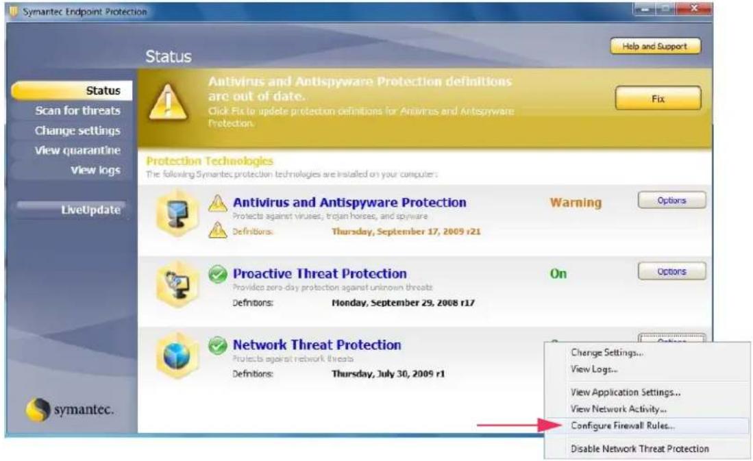
- Open the Symantec Control Center and click the Options button under Network Threat Protection.
2. Select Configure Firewall Rules from the menu.
The following screen displays:
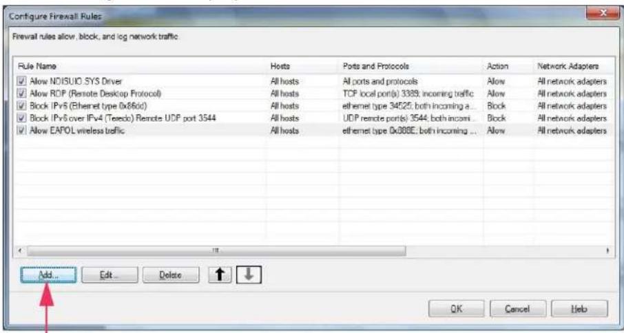
3. Click the Add button.
The following screen displays:
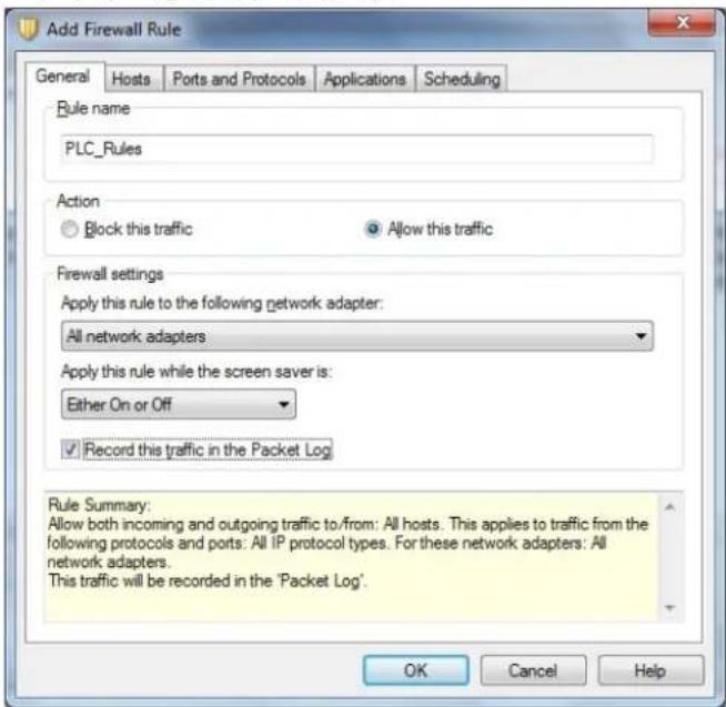
- In the General tab, do the following:
a. In the Rule name field, type a name for the firewall rule.
b. Select the Allow this traffic radio button.
c. Configure the firewall settings as shown or as you prefer.
- Click the Ports and Protocols tab.
The following screen displays:
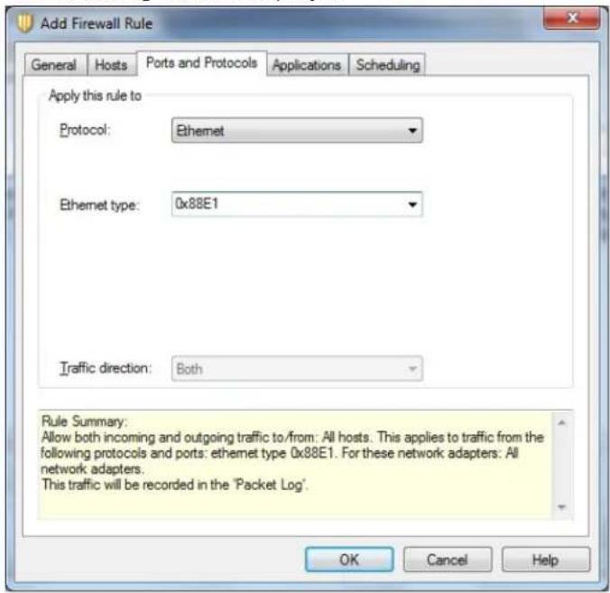
a. From the Protocol drop-down menu, select Ethernet.
b. In the Ethernet type field, type 0x88E1.
c. Click the OK button.
The rule displays in the firewall rule list.
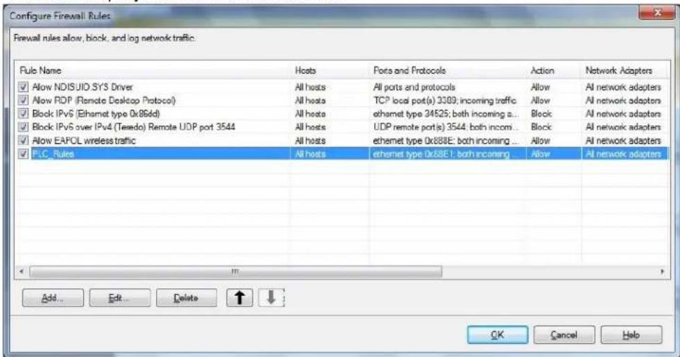
- Make sure that the check box next to the rule is selected and click the OK button.
- Restart the computer and launch NETGEAR genie.
The Powerline icon displays on the Network Map screen.
Supplemental Information

This appendix provides technical specifications and safety information for Powerline PassThru Adapters.
This appendix includes the following sections:
• XAV2602 Technical Specifications
• XAV5401 Technical Specifications
• XAV5602 Technical Specifications
• XAV6501 Technical Specifications
• XAV6504 Technical Specifications
- Safety Information
XAV2602 Technical Specifications
The XAV2602 adapter meets the technical specifications defined in the following table.
Table 2. XAV2602 technical specifications
| Feature Specification | |
| Data and routing protocols IEEE 802.3 (10BASE-T), IEEE 802.3u (100BASE-Tx) | |
| AC input 100–240V, 0.2A (max.) | |
| Socket outlet rating (max. load) AU: 10A, 250V; EU: 16A, 250V; NA: 15A, 125V; UK: 13A, 250V; | |
| Power consumption Normal: 4W, Power saving mode: <0.5W | |
| Dimensions 114 x 55 x 32.5 mm (4.49 x 2.17 x 1.28 in) | |
| Weight 0.190 kg (0.418 lb) | |
| Operating temperature 0° to 40°C (32° to 104°F) | |
| Operating humidity 10–90% maximum relative humidity, noncondensing | |
| Storage humidity 5–95% maximum relative humidity, noncondensing | |
| Security encryption type 128-bit AES | |
| MAC addresses 8 (active) / 16 (total): number of nodes that can be added to a single network | |
| Bandwidth 200 Mbps | |
| Compatibility | HomePlug AV IEEE 1901(Not compatible with HomePlug v1.0 or HomePlug v1.0 Turbo) |
| Data transfer rate | Up to 200 Mbps with real throughput greater than 80 Mbps |
| Frequency band | 2–75 Mbps |
| Modulation type | OFDM symbol modulation |
| Electromagnetic emissions | FCC Part 15 Class B; CE-EMC Class B; 3-home FCC Certificate |
| Safety agency approvals | UL Listed (UL 1950) /cUL IEC950; CE LVD; TUV CB, TUV CG |
XAV5401 Technical Specifications
The XAV5401 adapter meets the technical specifications defined in the following table.
Table 3. XAV5401 technical specifications
| Feature Specification | |
| Data and routing protocols IEEE 802.3 (10BASE-T), IEEE 802.3u (100BASE-Tx) | |
| AC input 100–240V, 0.2A (max.) | |
| Socket outlet rating (max. load) AU: 10A, 250V; EU: 16A, 250V; NA: 15A, 125V; UK: 13A, 250V; | |
| Power consumption Normal: 4W, Power saving mode: <0.5W | |
| Dimensions 114 x 55 x 32.5 mm (4.49 x 2.17 x 1.28 in) | |
| Weight 0.174 kg (0.384 lb) | |
| Operating temperature 0° to 40°C (32° to 104°F) | |
| Operating humidity 10–90% maximum relative humidity, noncondensing | |
| Storage humidity 5–95% maximum relative humidity, noncondensing | |
| Security encryption type 128-bit AES | |
| MAC addresses 8 (active) / 16 (total): number of nodes that can be added to a single network | |
| Bandwidth 500 Mbps | |
| Compatibility | HomePlug AV IEEE 1901(Not compatible with HomePlug v1.0 or HomePlug v1.0 Turbo) |
| Data transfer rate | Up to 500 Mbps with real throughput greater than 80 Mbps |
| Frequency band | 2–75 Mbps |
| Modulation type | OFDM symbol modulation |
| Electromagnetic emissions | CE-EMC Class B |
| Safety agency approvals | IEC60950; CE LVD |
XAV5602 Technical Specifications
The XAV5602 adapter meets the technical specifications defined in the following table.
Table 4. XAV5602 technical specifications
| Feature Specification | |
| Data and routing protocols IEEE 802.3 (10BASE-T), IEEE 802.3u (100BASE-Tx) | |
| AC input 100–240V, 0.2A (max.) | |
| Socket outlet rating (max. load) AU: 10A, | 250V; EU: 16A, 250V; NA: 15A, 125V; UK: 13A, 250V; |
| Power consumption Normal: 4W, Power saving mode: <0.5W | |
| Dimensions 114 x 55 x 32.5 mm (4.5 x 2.2 x 1.28 in) | |
| Weight 174 g (0.38 lb) | |
| Operating temperature 0° to 40°C (32° to 104°F) | |
| Operating humidity 10–90% maximum relative humidity, noncondensing | |
| Storage humidity 5–95% maximum relative humidity, noncondensing | |
| Security encryption type 128-bit AES | |
| MAC addresses 8 (active) / 16 (total): number of nodes that can be added to a single network | |
| Bandwidth 500 Mbps | |
| Compatibility | HomePlug AV IEEE 1901(Not compatible with HomePlug v1.0 or HomePlug v1.0 Turbo) |
| Data transfer rate | Up to 500 Mbps with real throughput greater than 80 Mbps |
| Frequency band | 2–75 Mbps |
| Modulation type | OFDM symbol modulation |
| Electromagnetic emissions | FCC Part 15 Class B; CE-EMC Class B; 3-home FCC Certificate |
| Safety agency approvals | UL Listed (UL 1950) /cUL IEC950; CE LVD; TUV CB, TUV CG |
XAV6501 Technical Specifications
The XAV6501 adapter meets the technical specifications defined in the following table.
Table 5. XAV6501 technical specifications
| Feature Specification | |
| Data and routing protocols IEEE 802.3 (10BASE-T), IEEE 802.3u (100BASE-Tx) | |
| AC input 100–240V, 0.2A (max.) | |
| Socket outlet rating (max. load) AU: 10A, | 250V; EU: 16A, 250V; NA: 15A, 125V; UK: 13A, 250V; |
| Power consumption Normal: 4W, Power saving mode: <0.5W | |
| Dimensions 114 x 55 x 32.5 mm (4.5 x 2.2 x 1.28 in) | |
| Weight 174 g (0.38 lb) | |
| Operating temperature 0° to 40°C (32° to 104°F) | |
| Operating humidity 10–90% maximum relative humidity, noncondensing | |
| Storage humidity 5–95% maximum relative humidity, noncondensing | |
| Security encryption type 128-bit AES | |
| MAC addresses 8 (active) / 16 (total): number of nodes that can be added to a single network | |
| Bandwidth 600 Mbps | |
| Compatibility | HomePlug AV IEEE 1901(Not compatible with HomePlug v1.0 or HomePlug v1.0 Turbo) |
| Data transfer rate | Up to 600 Mbps with real throughput greater than 80 Mbps |
| Frequency band | 2–75 Mbps |
| Modulation type | OFDM symbol modulation |
| Electromagnetic emissions | FCC Part 15 Class B; CE-EMC Class B; 3-home FCC Certificate |
| Safety agency approvals | UL Listed (UL 1950) /cUL IEC950; CE LVD; TUV CB, TUV CG |
XAV6504 Technical Specifications
The XAV6504 adapter meets the technical specifications defined in the following table.
Table 6. XAV6504 technical specifications
| Feature Specification | |
| Data and routing protocols IEEE 802.3 (10BASE-T), IEEE 802.3u (100BASE-Tx) | |
| AC input 100–240V, 0.2A (max.) | |
| Socket outlet rating (max. load) AU: 10A, | 250V; EU: 16A, 250V; NA: 15A, 125V; UK: 13A, 250V; |
| Power consumption Normal: 4W, Power saving mode: <0.5W | |
| Dimensions 114 x 55 x 32.5 mm (4.5 x 2.2 x 1.28 in) | |
| Weight 174 g (0.38 lb) | |
| Operating temperature 0° to 40°C (32° to 104°F) | |
| Operating humidity 10–90% maximum relative humidity, noncondensing | |
| Storage humidity 5–95% maximum relative humidity, noncondensing | |
| Security encryption type 128-bit AES | |
| MAC addresses 8 (active) / 16 (total): number of nodes that can be added to a single network | |
| Bandwidth 600 Mbps | |
| Compatibility | HomePlug AV IEEE 1901(Not compatible with HomePlug v1.0 or HomePlug v1.0 Turbo) |
| Data transfer rate | Up to 600 Mbps with real throughput greater than 80 Mbps |
| Frequency band | 2–75 Mbps |
| Modulation type | OFDM symbol modulation |
| Electromagnetic emissions | FCC Part 15 Class B; CE-EMC Class B; 3-home FCC Certificate |
| Safety agency approvals | UL Listed (UL 1950) /cUL IEC950; CE LVD; TUV CB, TUV CG |
Safety Information
Follow these safety guidelines to ensure your own personal safety and to help protect your system from potential damage:
- For national approvals (approval schemes other than CB), relevant national standards for plug, socket-outlet, and direct plug-in units (for example, US) shall also be consulted while testing and approving such products according to the national standards.
- Check the electrical current for any device plugged into the filtered AC socket. Do not exceed home and product outlet ratings and electrical requirements.
- The socket-outlet shall be installed near the equipment and be easily accessible.
- Only power cords are allowed to be inserted into the filtered AC socket; no other equipment with a direct plug-in is allowed. Power cords needs to be a maximum of 1 m long and a minimum of 0.75 ~mm^2 of cross-sectional area.
- Do not plug devices into the Powerline PassThru Adapter filtered AC outlet that exceed the product ratings. The output voltage of the filtered AC outlet is the same as the power outlet that the Powerline PassThru Adapter is plugged into. To help avoid damaging your system, be sure that the attached devices are electrically rated to operate with the power available in your location.
- If the input AC voltage is less than 100 Vac, the device plugged into the filtered AC socket of the Powerline PassThru Adapter might not perform as well as expected.
- DO NOT PLUG MAJOR HOME APPLIANCES into the filtered AC socket or into an attached power strip. The device is not intended to be used with home appliances such as air conditioners, power tools, space heaters, fans, hair dryers, ovens, or refrigerators.
- Actual data throughput will vary. Network conditions and environmental factors, including volume of network traffic, building materials and construction, and network overhead, lower actual data throughput rate.
- Do not service any product except as explained in your system documentation.
- Opening or removing covers that are marked with the triangular symbol with a lightning bolt can expose you to electrical shock. Only a trained service technician should service components inside these compartments.
- Use the product only with approved equipment.
- Allow the product to cool before removing covers or touching internal components.
- To help avoid damaging your system, be sure that the voltage selection switch (if provided) on the power supply is set to match the power available at your location:
- 110 volts (V), 60 hertz (Hz) in most of North and South America and some Far Eastern countries such as South Korea and Taiwan
- 100V, 50 Hz in eastern Japan and 100V, 60 Hz in western Japan
- 230V, 50 Hz in most of Europe, the Middle East, and the Far East
- The peripheral power cables are equipped with three-prong plugs to help ensure proper grounding. Do not use adapter plugs or remove the grounding prong from a cable.
Powerline PassThru Adapter
- Observe extension cable and power strip ratings. Make sure that the total ampere rating of all products plugged into the extension cable or power strip does not exceed 80 percent of the ampere ratings limit for the extension cable or power strip.
- To help protect your system from sudden, transient increases and decreases in electrical power, use a surge suppressor, line conditioner, or uninterruptible power supply (UPS).
• For additional safety instructions, see Appendix B, Notification of Compliance.
Safety Instructions and Precautions

WARNING:
Use the following safety guidelines to ensure your own personal safety and to help protect your product from potential damage. To reduce the risk of bodily injury, electrical shock, fire, and damage to the equipment, observe the following precautions.
- The socket-outlet shall be installed near the equipment and shall be easily accessible.
- Observe and follow service markings.
- If any of the following conditions occur, unplug the product from the electrical outlet and replace the part or contact your service provider/retailer:
- The power cable, extension cable, or plug is damaged.
- An object has fallen into the product.
- The product has been exposed to water.
- The product has been dropped or damaged.
- The product does not operate correctly when you follow the operating instructions.
- Keep your system away from radiators and heat sources. Also, do not block cooling vents.
- Do not spill food or liquids on your system components, and never operate the product in a wet environment.
- Do not push any objects into the openings of your system. Doing so can cause fire or electric shock by shorting out interior components.
- Operate the product only from the type of external power source indicated on the electrical ratings label.
- Also, be sure that attached devices are electrically rated to operate with the power available in your location.
- Use only approved power cables. If you have not been provided with a power cable for your system or for any AC-powered option intended for your system, purchase a power cable that is approved for use in your country. The power cable must be rated for the product and for the voltage and current marked on the product's electrical ratings label.
Powerline PassThru Adapter
The voltage and current rating of the cable should be greater than the ratings marked on the product.
- T o help prevent electric shock, plug the system and peripheral power cables into properly grounded electrical outlets.
- Do not use adapter plugs. If you must use an extension cable, use a three-wire cable with properly grounded plugs.
- Observe extension cable and power strip ratings. Make sure that the total ampere rating of all products plugged into the extension cable or power strip does not exceed 80 percent of the ampere ratings limit for the extension cable or power strip.
- T o help protect your system from sudden, transient increases and decreases in electrical power, use a surge suppressor, line conditioner, or uninterruptible power supply (UPS).
- Position system cables and power cables carefully; route cables so that they cannot be stepped on or tripped over. Be sure that nothing rests on any cables.
- Do not modify power cables or plugs.
• Always follow your local and national wiring rules.
Regulatory Compliance Information
This section includes user requirements for operating this product in accordance with National laws for usage of radio spectrum and operation of radio devices. Failure of the end-user to comply with the applicable requirements may result in unlawful operation and adverse action against the end-user by the applicable National regulatory authority.
This product's firmware limits operation to only the channels allowed in a particular Region or Country. Therefore, all options described in this user's guide may not be available in your version of the product.
Europe – EU Declaration of Conformity
Products bearing the marking comply with the following EU directives:
• EMC Directive 2004/108/EC
• Low Voltage Directive 2006/95/EC
If this product has telecommunications functionality, it also complies with the requirements of the following EU Directive:
• R&TTE Directive 1999/5/EC
Compliance with these directives implies conformity to harmonized European standards that are noted in the EU Declaration of Conformity.
FCC Requirements for Operation in the United States
FCC Information to User
This product does not contain any user serviceable components and is to be used with approved antennas only. Any product changes or modifications will invalidate all applicable regulatory certifications and approvals
This device complies with Part 15 of the FCC Rules. Operation is subject to the following two conditions: (1) This device may not cause harmful interference, and (2) this device must accept any interference received, including interference that may cause undesired operation.
FCC Guidelines for Human Exposure
This equipment complies with FCC radiation exposure limits set forth for an uncontrolled environment. This equipment should be installed and operated with minimum distance of 20 cm between the radiator and your body. This transmitter must not be co-located or operating in conjunction with any other antenna or transmitter.
Powerline PassThru Adapter
FCC Declaration Of Conformity
We, NETGEAR, Inc., 350 East Plumeria Drive, San Jose, CA 95134, declare under our sole responsibility that the Powerline PassThru Adapter complies with Part 15 of FCC Rules. Operation is subject to the following two conditions:
• This device may not cause harmful interference, and
- This device must accept any interference received, including interference that may cause undesired operation.
FCC Radio Frequency Interference Warnings & Instructions
This equipment has been tested and found to comply with the limits for a Class B digital device, pursuant to Part 15 of the FCC Rules. These limits are designed to provide reasonable protection against harmful interference in a residential installation. This equipment uses and can radiate radio frequency energy and, if not installed and used in accordance with the instructions, may cause harmful interference to radio communications. However, there is no guarantee that interference will not occur in a particular installation. If this equipment does cause harmful interference to radio or television reception, which can be determined by turning the equipment off and on, the user is encouraged to try to correct the interference by one or more of the following methods:
- Reorient or relocate the receiving antenna.
- Increase the separation between the equipment and the receiver.
- Connect the equipment into an electrical outlet on a circuit different from that which the radio receiver is connected.
- Consult the dealer or an experienced radio/TV technician for help.
Modifications made to the product, unless expressly approved by NETGEAR, Inc., could void the user's right to operate the equipment.
Canadian Department of Communications Radio Interference Regulations
This digital apparatus, the Powerline PassThru Adapter, does not exceed the Class B limits for radio-noise emissions from digital apparatus as set out in the Radio Interference Regulations of the Canadian Department of Communications.
This Class [B] digital apparatus complies with Canadian ICES-003.