
SF 228T Plus - Speaker Extron - Free user manual and instructions
Find the device manual for free SF 228T Plus Extron in PDF.

| Product Type | Ceiling Speaker |
| Brand | Extron |
| Model | SF 228T Plus |
| Dimensions | 11.2 x 11.2 x 8.9 in (28.4 x 28.4 x 22.6 cm) |
| Weight | 8.6 lb (3.9 kg) |
| Power Handling | 30 W RMS, 60 W peak |
| Frequency Response | 70 Hz – 20 kHz |
| Impedance | 8 ohms |
| Sensitivity | 89 dB (1W/1m) |
| Driver Configuration | 2-way: 8" woofer, 1" tweeter |
| Mounting Type | Flush mount, includes tile bridge |
| Coverage Angle | 90° conical |
| Transformer Taps | 70V/100V: 30W, 15W, 7.5W, 3.8W |
| Input Connection | Screw terminal block (4-pin) |
| Enclosure Material | Steel with off-white paint |
| Grille | Perforated metal, paintable |
| Safety Rating | UL listed, CE compliant |
| Operating Temperature | 32°F to 104°F (0°C to 40°C) |
| Warranty | 3 years |
| Included Accessories | Mounting hardware, cutout template |
Frequently Asked Questions - SF 228T Plus Extron
User questions about SF 228T Plus Extron
0 question about this device. Answer the ones you know or ask your own.
Ask a new question about this device
Download the instructions for your Speaker in PDF format for free! Find your manual SF 228T Plus - Extron and take your electronic device back in hand. On this page are published all the documents necessary for the use of your device. SF 228T Plus by Extron.
USER MANUAL SF 228T Plus Extron
SF 228T Plus • User Guide
The Extron SF 228T Plus Sound Field® 2-way ceiling speaker features a low profile design that houses an 8-inch woofer and 1.1-inch dome tweeter and has the appearance of a standard ventilation grill. All drivers and components above the ceiling are hidden behind the grill.
natural_image
3D rendered mesh structure resembling a roof or turbine blade, with no visible text or symbolsThe SF 228T Plus uses plenum rated ceiling spaces and can be mounted into a standard 2 feet x 2 feet or 2 feet x 4 feet (with supplied t-rail crosspieces) false ceiling tile space on a T-bar grid, or, a frame installed in solid ceilings.
FCC Class A Notice
This equipment has been tested and found to comply with the limits for a Class A digital device, pursuant to part 15 of the FCC rules. The Class A limits provide reasonable protection against harmful interference when the equipment is operated in a commercial environment. This equipment generates, uses, and can radiate radio frequency energy and, if not installed and used in accordance with the instruction manual, may cause harmful interference to radio communications. Operation of this equipment in a residential area is likely to cause interference. This interference must be corrected at the expense of the user.
NOTE: For more information on safety guidelines, regulatory compliances, EMI/EMF compatibility, accessibility, and related topics, see the "Extron Safety and Regulatory Compliance Guide" on the Extron website.
Specifications
Product specifications are available on the Extron website, www.extron.com.
Features
- Drop-in 2-way speakers for suspended ceilings.
• UL-2043 plenum rated enclosure. - An 8-inch, (203 mm), full range woofer provides extended low frequency response.
• A 1.1-inch, (28 mm), dome tweeter provides extended high frequency response. - The white perforated grille matches the appearance of air conditioning vents.
- 8 ohm direct or 70/100 Volt operation with 64, 32, 16, and 8 watt selectable power taps accessed with speaker wiring connections inside the rear panel.
• Frequency range of 59 Hz to 22 kHz. - 90 watts continuous pink noise, 180 watts continuous program rated.
- 90^ conical coverage.
- Low profile enclosure for plenum environments.
- 5 year parts and labor warranty.
Application Example
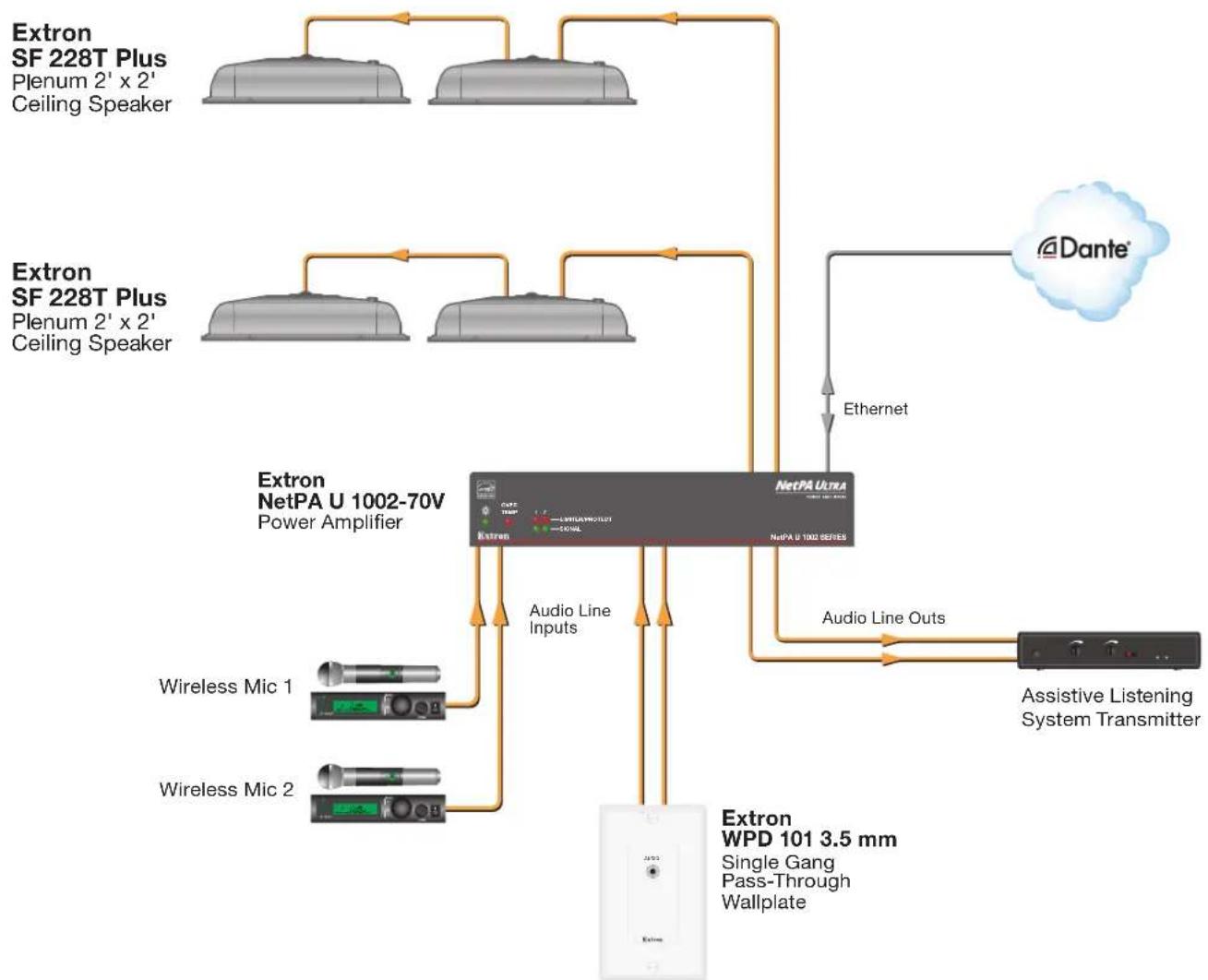
The following illustration shows one way to configure a system using the SF 228T Plus.
flowchart
graph TD
    A["Extron SF 228T Plus\nPlenum 2' x 2'\nCeiling Speaker"] --> B["Extron NetPA U 1002-70V\nPower Amplifier"]
    C["Extron SF 228T Plus\nPlenum 2' x 2'\nCeiling Speaker"] --> B
    B --> D["Extron WPD 101 3.5 mm\nSingle Gang Pass-Through Wallplate"]
    B --> E["Audio Line Inputs"]
    B --> F["Audio Line Outs"]
    B --> G["Airplane"]
    B --> H["Wireless Mic 1"]
    B --> I["Wireless Mic 2"]
    B --> J["Outs/Transmit"]
    B --> K["Antenna"]
    L["Dante"] --> M["Ethernet"]
    M --> N["NetPA Ultra\nNetPA U 1002 SERIES"]
    N --> O["Audio Line Inputs"]
    N --> P["Audio Line Outs"]
    O --> Q["Assistive Listening System Transmitter"]
    P --> Q
Figure 1. SF 228T Plus Application Diagram
Installation
This section discusses how to install the SF 228T Plus speaker and includes:
• Installation Considerations
• Installing the Speakers
• Wiring the Speakers
• Completing the Installation
CAUTION:
Installation Considerations
• Installation of conduit and conduit adapters must conform to all applicable building codes and local ordinances.
• Installation in a plenum-rated environment requires a wire gauge of 12 AWG to 18 AWG. Conduit may be required.
- If using seismic supports, the installer provides the safety cable.
NOTE: Observe all applicable building codes and local ordinances when installing the speaker.
- Wiring connections depend on the audio system the speakers are being installed with.
Installing the Speakers
- Power down — Power down all attached devices before proceeding.
- Remove the suspended ceiling tile — Remove the ceiling tile where the SF 228T Plus will be installed and lay it aside.
- Remove the terminal cover plate — Loosen (do not remove) the two screws in the keyhole slots on the top terminal cover plate and remove the cover plate as shown in figure 2.
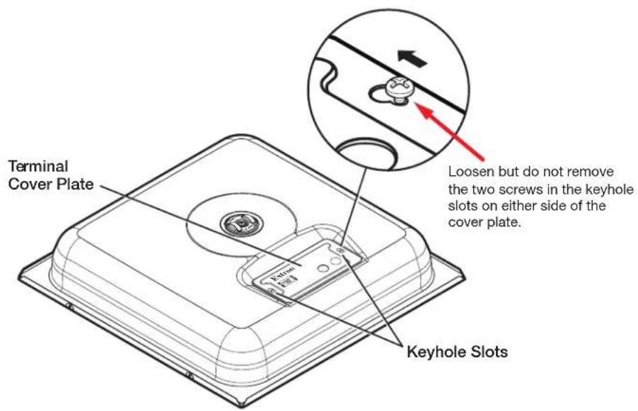
Figure 2. Remove Terminal Cover Plate
4. Routing cables through the terminal cover plate:
a. When using flexible conduit — Insert the conduit into the cover plate opening using an appropriate conduit adapter, and secure the conduit to the plate (see figure 3).
NOTE: If running cable to an additional speaker through conduit, remove the secondary knock-out and insert the conduit into the hole.
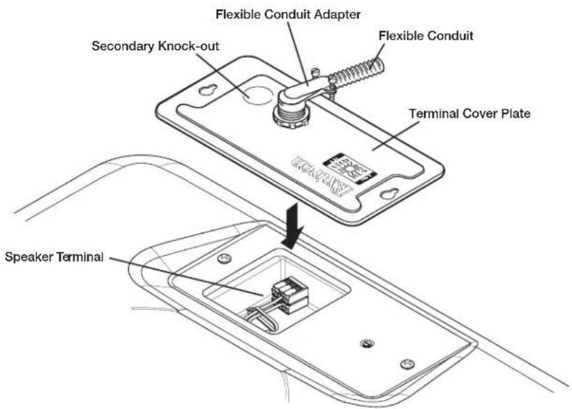
NOTE: Installation of conduit and conduit adapters should conform to all applicable building codes and local ordinances.
b. When using speaker wires without conduit — Secure the cable clamp adapter (included) to the cover plate and insert the wires through the clamp (see figure 4).
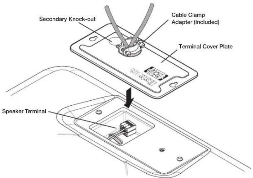
Figure 4. Cable Clamp Adapter
c. Tlghen the adapter screws to hold the wires firmly in place.
Wiring the Speakers
Inside the speaker compartment, red (+) and black (-) speaker wires are pre-attached to separate three-pole splicing connectors.
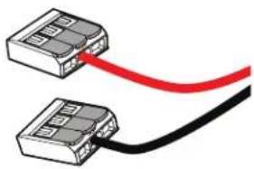
natural_image
Two connected electronic components with a red and black cable (no text or symbols visible)Figure 5. Speaker Wires with Splicing Connectors
- Route the two red and black power amplifier or speaker wires through the cable access opening. if conduit is used, pull the wire ends out from the conduit casing.
- Using the guide on the side of the splicing connector, strip .43 inch (11 mm) from the ends of the protruding red and black wires.
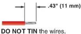
Figure 6. Wire-stripping Measurement
- Lock the red and black power amplifier or speaker wires into their respective 3-pole splicing connectors.
a. Lift one lever of the red-wired 3-pole splicing connector ① and insert the stripped end of the red wire into an empty pole of the connector ②. Press the lever down to lock the red wire in place ③ (see figure 7).
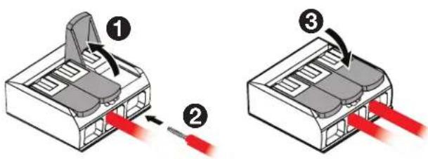
Figure 7. Locking the Red Power Amplifier Wire
b. Next, lift one lever of the other (black-wired) 3-pole splicing connector ① and insert the stripped end of the black wire into an empty pole of the connector ②. Press the lever down to lock the black wire in place ③.
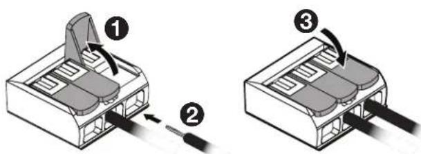
Figure 8. Locking the Black Power Amplifier Wire
NOTE: Each pole of the splicing connector is capable of accepting up to 12 AWG wire.
4. To wire a second speaker —
a. Measure the distance between the two speakers intended installation points, add an extra foot or third of a meter for safety, and cut that length in speaker wire cable.
TIP: Estimate the distance by counting the number of 2 x 2 inch or 2 x 4 inch ceiling tiles.
b. Remove the secondary knock-out from the terminal cover plate of the primary speaker, and route one end of the speaker cable through the secondary cable access opening. If conduit is used, pull the wires through and out of the conduit.
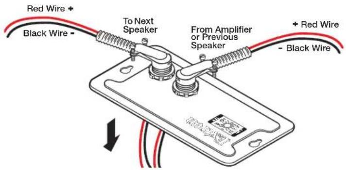
Figure 9. Routing Second Speaker Wires through Primary Speaker Cover Plate
c. Following steps 2 and 3 on page 5, strip and lock the red and black wire ends into their respective connectors.
d. For wiring the second speaker, repeat steps 1 of Installing the Speakers (page 2) through step 3 of Wiring the Speakers (page 3).
e. For wiring additional speakers, repeat step 4 as necessary.
-
Replace the terminal cover plate and tighten the two cover plate screws that were loosened in step 3 of Installing the Speakers on page 3.
-
Set the rotary tap selector switch to the appropriate power setting using a small screwdriver.
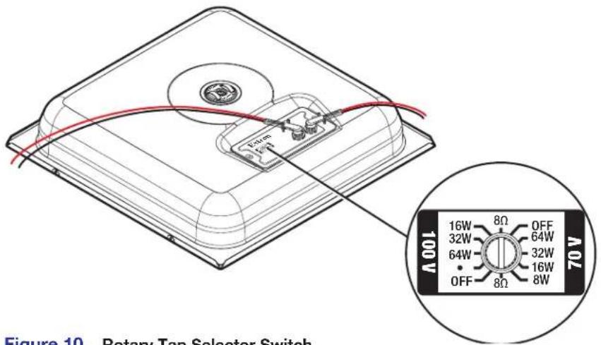
Figure 10. Rotary Tap Selector Switch
ATTENTION:
Completing the Installation
NOTE: Observe all applicable building codes and local ordinances when installing the speaker.
1. Ceiling tile installation —
a. For installation in a 2 feet x 2 feet ceiling tile, remove a tile and place the speaker on the existing support rails as shown in figure 12.
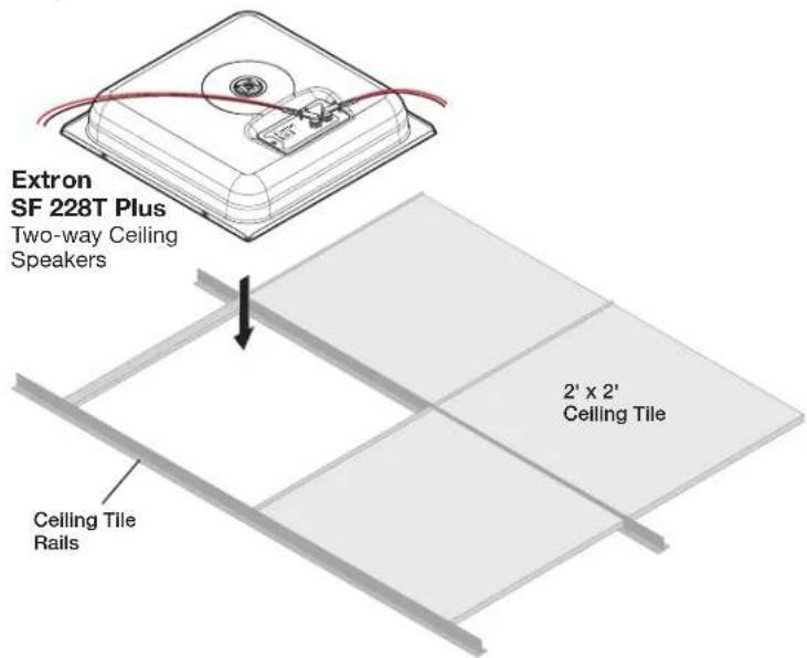
Figure 11. 2 Feet x 2 Feet Ceiling Tile Installation
b. For installation in a 2 feet x 4 feet ceiling tile, remove a tile and cut the tile in half. Install the supplied T-rail crosspiece, then replace the half-tile as shown in figure 13.
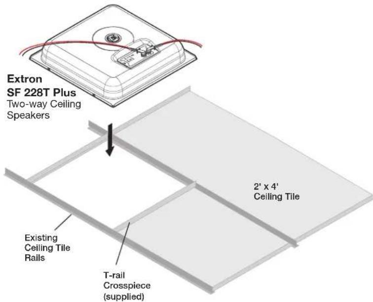
Figure 12. 2 Feet x 4 Feet Ceiling Tile Installation
Set the speaker in place in the ceiling and position it so the speaker edges are hidden by the existing rails or T-rails.
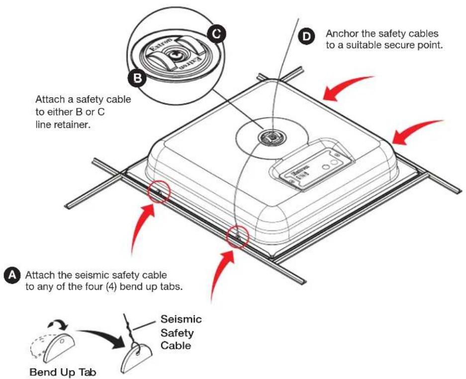
- If seismic safety lines are being used, install them now. In addition to the tie off at B and C, Extron recommends a tie off on one of the four available tabs at A. See the illustration below.
NOTE: Speaker wiring has been omitted for clarity.
CAUTION:
a. Shut off power to all connected equipment.
b. Temporarily remove a ceiling tile adjacent to the speaker and set it aside.
c. Attach seismic safety cable to one or both line retainer loops at B and C.
d. Attach seismic safety cable to at least one of the four (4) seismic bendout tabs located on either side of the speaker, A.
e. Attach the other end of the cables (D) to a sturdy part of the building (studs, roof struts, support girders or similar structure).
f. For additional support lines, repeat as needed.
g. Replace the ceiling tile removed in step b.
- Power on the amplifier, test and make any source device and system adjustments following the amplifier operating instructions.
For information on safety guidelines, regulatory compliances, EMI/EMF compatibility, accessibility, and related topics, see the Extron Safety and Regulatory Compliance Guide on the Extron website.
- SF 228T Plus • User Guide
- FCC Class A Notice
- Specifications
- Features
- Application Example
- Installation
- CAUTION:
- Installation Considerations
- Installing the Speakers
- Routing cables through the terminal cover plate:
- Wiring the Speakers
- To wire a second speaker —
- ATTENTION:
- Completing the Installation
- Ceiling tile installation —
Brand : Extron
Model : SF 228T Plus
Category : Speaker