
CS 3T - Loudspeaker Extron - Free user manual and instructions
Find the device manual for free CS 3T Extron in PDF.


| Product Type | Ceiling Speaker |
| Brand | Extron |
| Model | CS 3T |
| Driver Size | 3 inches |
| Frequency Response | 100 Hz – 20 kHz |
| Impedance | 8 ohms (bypass transformer) |
| Power Handling (RMS) | 10 W |
| Sensitivity (1W/1m) | 89 dB |
| Transformer Taps | 70V/100V: 1.5W, 3W, 6W |
| Dimensions (Diameter x Depth) | 6.5 in x 3.5 in (165 mm x 89 mm) |
| Weight | 1.5 lbs (0.68 kg) |
| Mounting Type | Ceiling mount with tile bridge |
| Connector Type | 4-pin removable screw terminal |
| Color | White (paintable) |
| Material | ABS baffle, steel backcan |
| Operating Temperature | 32°F – 104°F (0°C – 40°C) |
| Safety Compliance | UL 2043 plenum rated |
| Included Accessories | Tile bridge, cutout template, mounting screws |
| Maintenance | Clean with dry cloth; do not use liquids |
| Spare Parts / Repair | No user-serviceable parts; contact Extron for service |
Frequently Asked Questions - CS 3T Extron
User questions about CS 3T Extron
0 question about this device. Answer the ones you know or ask your own.
Ask a new question about this device
Download the instructions for your Loudspeaker in PDF format for free! Find your manual CS 3T - Extron and take your electronic device back in hand. On this page are published all the documents necessary for the use of your device. CS 3T by Extron.
USER MANUAL CS 3T Extron
This setup guide contains installation information about the CS 3T speaker cartridge for the Extron CS 123T SpeedMount® Ceiling Speaker System. The CS 3T can be installed as a standalone speaker or in conjunction with the CS 120P plenum rated enclosure. When a CS 3T speaker is installed in a CS 120P enclosure, the entire assembly is plenum rated.
WARNING: May result in serious injury. Installation and service must be performed by authorized personnel only.
NOTE: Installation of conduit and conduit adapters must conform to all applicable building codes and local ordinances.
Installing the CS 3T in a Suspended Ceiling
For hard ceiling installations, see the CS 123T User Guide.
- Remove power from all devices.
NOTE: If the baffle and grille are to be painted, see the CS 3T and CS 120P User Guide for more information.
- Cut a hole for the CS 3T. Use the provided cutout template to outline the hole to be cut in the ceiling tile as described below.
a. Remove the ceiling tile and draw diagonal lines across the non-visible side from opposite corners to locate its center. Mark the intersection where the lines cross.
b. Position the center hole of the cutout template directly over the center of the tile, marked in step a.
c. Trace a circle on the ceiling tile as follows:
For installations in ceilings that are NOT fiberglass or when installing the speakers in an open back configuration: Trace a circle around the cutout template.
NOTE: The fiberglass tile adapters are not needed and can be discarded.
For installations in a fiberglass tile ceiling with the CS 120P:
NOTE: A set of fiberglass tile adapters is provided with both the CS 3T and the CS 120P. Only one set is needed to install the CS 3T with the CS 120P kit in fiberglass tile.
i. Place the fiberglass tile adapter around the outer diameter of the template that was positioned in step b.
ii. Trace a circle around the outer diameter of the adapter.
d. Cut out the circle traced in the ceiling tile.
e. Replace the ceiling tile in the ceiling.
-
Remove the adjacent ceiling tile next to the tile where the speaker will be installed.
-
Install the CS 120P or ceiling mount kit.
• If using the CS 120P, see the CS 120P Setup Guide to install it.
- If not using the CS 120P, attach two V-rails and one C-ring across the tile above the hole that was cut in step 2 (see the illustration below). The fiberglass tile adapter is not needed.

- Route the speaker wires through the ceiling tile hole.
- Remove the grille carefully from the CS 3T.
NOTE: Grille hooks are provided for grille removal, if needed.
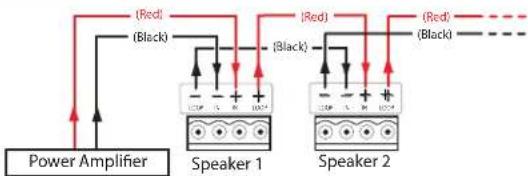
- Attach speaker wires from the ceiling tile hole to the included 4-pole captive screw connector using one of the three methods shown below.
NOTES:
• See the wire gauge table below for the maximum number of wires per terminal.
- Do not tin the wires. Tinned wires do not remain secure in the captive screws and can break easily after several bends.
• See the CS 3T and CS 120P User Guide for detailed information on wiring configurations.
1
flowchart
graph TD
    A["Power Amplifier"] --> B["Speaker 1"]
    A --> C["Speaker 2"]
    B --> D["Red (Black)"]
    B --> E["Black (Red)"]
    C --> F["Red (Black)"]
    C --> G["Black (Red)"]
Wiring Multiple Speakers Using Loop-through When a chain of speakers is wired this way, disconnecting one speaker removes power from all downstream speakers.
2

flowchart
graph TD
    A["Power Amplifier"] --> B["Speaker 1"]
    A --> C["Speaker 2"]
    B --> D["Red (Black)"]
    B --> E["Red (Black)"]
    C --> F["Red (Black)"]
    C --> G["Red (Black)"]
Wiring Multiple Speakers in Parallel When a chain of speakers is wired this way, disconnecting one speaker does not remove power from the remaining speakers in the chain.
3

flowchart
graph TD
    A["Speaker 1"] -->|Red| B["Power Amplifier"]
    A -->|Black| C["Speaker 1"]
    B --> D["Power Amplifier"]
    C --> E["Speaker 1"]
Wiring a Single Speaker
Wire Gauge Table
| Number of Wires per Connection Point | Maximum Wire Gauge |
| 1 | 12 AWG |
| 2 | 16 AWG |
| 4 | 18 AWG |
- Insert the captive screw plug into the 4-pole receptacle on the transformer cap.
- Secure the speaker wire to the strain relief tie-down point, using the included zip tie.

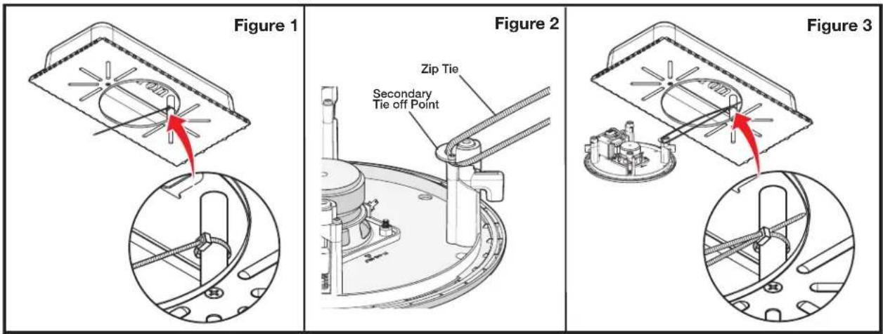
- Attach secondary support lines (CS 120P configuration).
NOTE: Skip this step if the speaker is to be used in the open back configuration and proceed to step 11)
a. Insert the free end of the zip tie, located inside of the CS 120P (see figure 1 below), through the secondary attachment point of the speaker (see figure 2 below).
b. Insert the free end of the zip tie into the locking connector on the opposite end of the zip tie (see figure 3 below).
NOTE: Leave enough slack in the zip tie so that the speaker can be securely installed in the enclosure.
c. Tighten the zip tie.
- Mount the CS 3T.
a. Insert the CS 3T through the bottom of the hole in the ceiling tile that was cut in step 2 on page 1.
b. Tighten the four screws (clockwise) until the speaker is securely clamped to the ceiling.

ATTENTION:
c. If using the CS 120P, proceed to step 13 on page 4.
- Attach secondary support lines (open back configuration).

ATTENTION:
- Do not allow any slack in the secondary support line.
-
Ne laissez aucun jeu au niveau du filin de sécurité secondaire.
-
Replace the adjacent tile that was removed in step 3 on page 1.
- Set the rotary tap selector switch to the appropriate setting, using a small screwdriver.

- Install the grille. Position the outer perimeter of the grille into the groove of the speaker baffle. Six magnets pull the grille securely into place.

NOTE: Grille hooks are provided for removal of the grille after installation.
| Extron Headquarters+1.800.633.9876 (Inside USA/Canada Only) | Extron Asia+65.6383.4400 | Extron China+86.21.3760.1568 | Extron Korea+82.2.3444.1571 |
| Extron Europe+31.33.453.4040 | Extron Japan+81.3.3511.7655 | Extron Middle East+971.4.299.1800 | Extron India+91.80.3055.3777 |
© 2014 Extron Electronics — All rights reserved. All trademarks mentioned are the property of their respective owners. www.extron.com

Brand : Extron
Model : CS 3T
Category : Loudspeaker