
SM 3 - Speaker Extron - Free user manual and instructions
Find the device manual for free SM 3 Extron in PDF.


| Product Type | Surface Mount Speaker |
| Driver Size | 3-inch full-range driver with paper cone |
| Frequency Response | 75 Hz to 18 kHz, -10 dB (full space) |
| Power Handling (Continuous Pink Noise) | 15 W (per IEC 60268-5) |
| Power Handling (Continuous Program) | 30 W |
| Enclosure Material | UV stabilized, flame retardant PC/ABS plastic |
| Color Options | Black or white finishes |
| Mounting System | Concealed mounting with 0° and 10° mounting plates |
| Connection Type | Automatic gold-plated contact pins |
| Security Feature | Hidden release mechanism and security key locking |
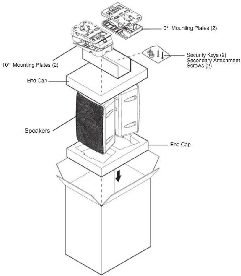
| Included Accessories | Two mounting plates (0° and 10°), two security keys, two secondary attachment screws, end caps |
| Warranty | 5 years |
Frequently Asked Questions - SM 3 Extron
User questions about SM 3 Extron
0 question about this device. Answer the ones you know or ask your own.
Ask a new question about this device
Download the instructions for your Speaker in PDF format for free! Find your manual SM 3 - Extron and take your electronic device back in hand. On this page are published all the documents necessary for the use of your device. SM 3 by Extron.
USER MANUAL SM 3 Extron
SpeedMount® Surface Mount Speakers
natural_image
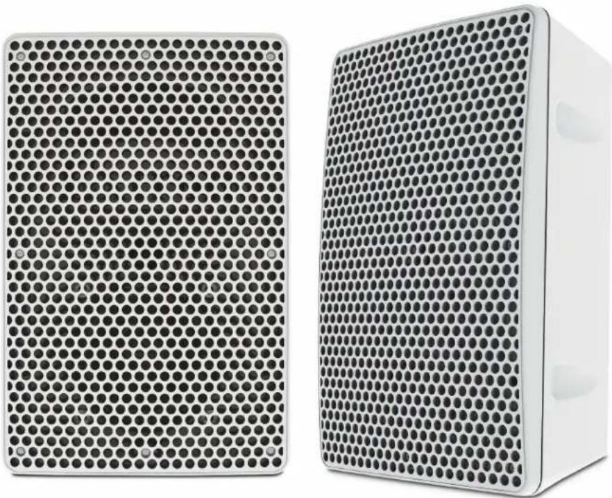
Two white rectangular speakers with a grid-patterned panel, no visible text or symbolsSafety Instructions
Safety Instructions • English
WARNING: This symbol, ⚠, when used on the product, is intended to alert the user of the presence of uninsulated dangerous voltage within the product's enclosure that may present a risk of electric shock.
ATTENTION: This symbol, △ when used on the product, is intended to alert the user of important operating and maintenance (servicing) instructions in the literature provided with the equipment.
For information on safety guidelines, regulatory compliances, EMI/EMF compatibility, accessibility, and related topics, see the Extron Safety and Regulatory Compliance Guide, part number 68-290-01, on the Extron website, www.extron.com.
Chinese Traditional (繁體中文)
Conventions Used in this Guide
Notifications
The following notifications are used in this guide:
CAUTION: A caution indicates a situation that may result in minor injury.
ATTENTION: Attention indicates a situation that may damage or destroy the product or associated equipment.
NOTE: A note draws attention to important information.
Specifications Availability
Product specifications are available on the Extron website, www.extron.com.
Copyright
© 2013 Extron Electronics. All rights reserved.
Trademarks
All trademarks mentioned in this guide are the properties of their respective owners.
The following registered trademarks ^® , registered service marks ^SM , and trademarks ^TM are the property of RGB Systems, Inc. or Extron Electronics:
| Registered Trademarks ^(8) |
| AVTrac, Cable Cubby, CrossPoint, eBUS, EDID Manager, EDID Minder, Extron, Flat Field, GlobalViewer, Hideaway, Inline, IP Intercom, IP Link, Key Minder, LockIt, MediaLink, PlenumVault, PoleVault, PowerCage, PURE3, Quantum, SoundField, SpeedMount, SpeedSwitch, System Integrator, TeamWork, TouchLink, V-Lock, VersaTools, VN-Matrix, VoiceLift, WallVault, WindoWall, XTP and XTP Systems |
| Registered Service Mark ^(SM) : S3 Service Support Solutions |
| Trademarks ^(TM) |
| AAP, AFL (Accu-Rate Frame Lock), ADSP (Advanced Digital Sync Processing), AIS (Advanced Instruction Set), Auto-Image, CDRS (Class D Ripple Suppression), DDSP (Digital Display Sync Processing), DMI (Dynamic Motion Interpolation), Driver Configurator, DSP Configurator, DSVP (Digital Sync Validation Processing), FastBite, FOXBOX, IP Intercom HelpDesk, MAAP, MicroDigital, ProDSP, QS-FPC (QuickSwitch Front Panel Controller), Scope-Trigger, SIS, Simple Instruction Set, Skew-Free, SpeedNav, Triple-Action Switching, XTP, XTP Systems, XTRA, ZipCaddy, ZipClip |
Contents
Introduction.... 1
About the SM 3 Speaker .... 1
Features 1
Application Example 2
Installation....3
Installing the Speaker Mounting Plate .... 3
Mounting to a Wall Box....4
Mounting to a Wall Stud.... 5
Wiring the Speaker Mounting Plate......6
Attaching the Speaker to the Mounting Plate.....9
Step 1: Attaching the Speaker......9
Step 2: Using the Security Key to Lock and Unlock the Speaker....10
Removing the Speaker from the Mounting Plate....11
Attaching a Secondary Support Cable....12
Reference Information 13
Packaging 13
Introduction
This user guide contains information about the Extron SM 3 SpeedMount Surface Mount Speaker.
About the SM 3 Speaker
The SM 3 speaker is a low profile surface-mount speaker system that features a three-inch full-range driver with very wide audio dispersion. Speaker mounting incorporates a separate mounting plate that can be attached directly to a wall or to an electrical box behind the wall. The speaker wiring attaches to the mounting plate so that the speaker can easily slide into the mounting plate, making electrical contact between the plate and the contacts on the speaker. A built-in locking mechanism between the speaker and the mounting plate also prevents the speaker from being removed by unauthorized personnel. The speaker may be easily removed by depressing a hidden release mechanism that does not require tools.
Features
- Concealed mounting system — Exclusive concealed mounting system included with 0° and 10° mounting plates.
- Mounting plate — Each speaker comes with a mounting plate that accommodates both American (3.25 inches) and European (60 mm) electrical boxes. Two types of mounting plates are provided with each speaker for both a flat (ADA compliant – protruding less than four inches off of the wall) and an angled (10°) mounting profile.
• 3-inch driver with paper cone — Full range with a wide audio dispersion. - Rated power — 15 W continuous pink noise (per IEC 60268-5); 30 W continuous program.
• Frequency response — 75 Hz to 18 kHz, -10 dB (full space)
• Bass-reflex, UV stabilized, flame retardant PC/ABS plastic enclosure
• Color options — Available in black or white finishes.
• Automatic speaker connection — Recessed gold-plated contact pins integrated into each speaker automatically make an electrical connection when the speaker is mounted to the wall mounting plate. - Hidden release mechanism — The speaker automatically locks on to the wall mounting adapter to prevent tampering, but a hidden release mechanism allows the speaker to be quickly unlocked without the use of tools.
• Security key — A special key allows the speaker to be locked or unlocked to the mounting plate.
Application Example
The illustration below is one example of configuring a system using the SM 3 speakers.
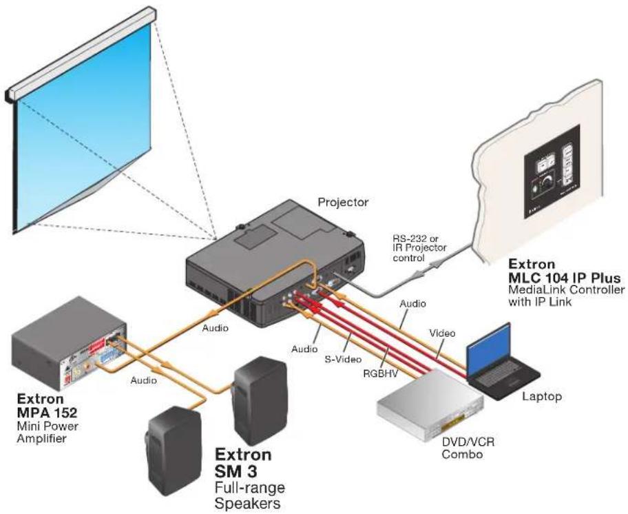
flowchart
graph TD
    A["Extron MPA 152\nMini Power Amplifier"] -->|Audio| B["Extron SM 3\nFull-range Speakers"]
    B -->|Audio| C["Projector"]
    C -->|Audio| D["Extron MLC 104 IP Plus\nMediaLink Controller with IP Link"]
    C -->|S-Video| E["RGBHV"]
    C -->|Audio| F["Laptop"]
    C -->|RS-232 or IR Projector control| G["Extron MLC 104 IP Plus\nMediaLink Controller with IP Link"]
    B --> H["DVD/VCR Combo"]
Installation
The Installation section describes:
• Installing the Speaker Mounting Plate
• Attaching the Speaker to the Mounting Plate
• Removing the Speaker from the Mounting Plate
• Attaching a Secondary Support Cable
Installing the Speaker Mounting Plate
The SM 3 speaker comes with two types of speaker mounting plates:
- 0° plate — The 0° plate allows the speaker to be mounted flat on a vertical wall with the speaker protruding less than four inches (ADA compliant) from the wall surface (see the illustration below).
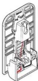
0° Mounting Plate
- 10° mounting plate — The 10° mounting plate allows the speaker to be installed at a 10 degree angle so that the speaker can be pointed down from an elevated position (see the illustration below).
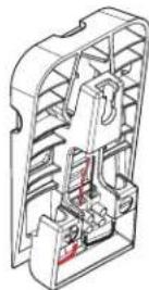
° Mounting Plate
The mounting plate can be installed vertically or horizontally.
The mounting plate can be installed to a wall box (see "Mounting to a Wall Box" below) or to a wall stud (see "Mounting to a Wall Stud" on the following page).
Mounting to a Wall Box
NOTE: Mounting hardware is not provided.
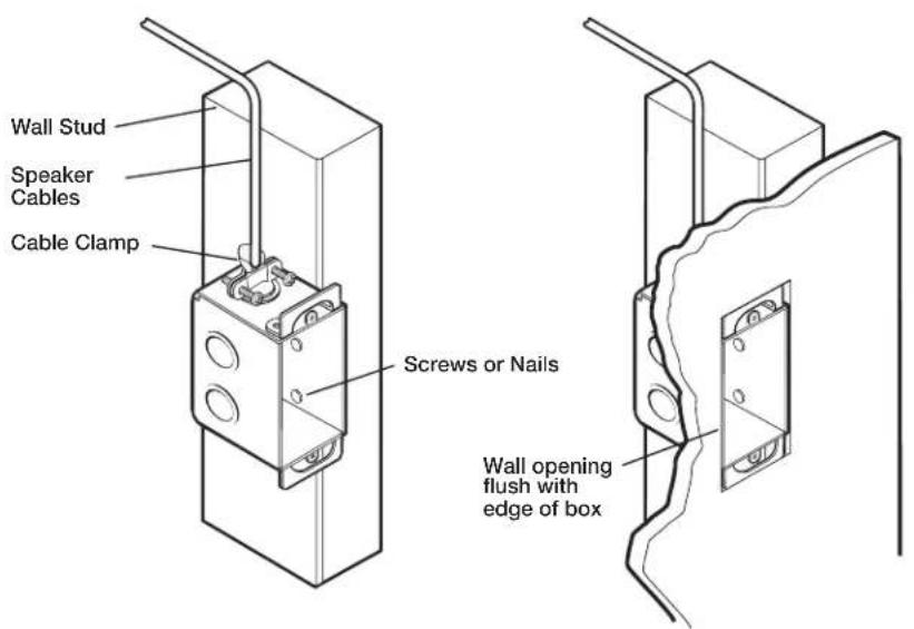
- Install the speaker cables into the wall or conduit before installing the wall box.
-
Place the wall box against the installation surface, and mark the guidelines for the opening on the wall.
-
Cut the material from the marked area.
-
Insert the wall box to check the size of the opening and fit. Enlarge or smooth the edges of the opening if needed.
-
Feed cables through punch-out holes of the wall box leaving enough slack for the speaker connections and secure them with cable clamps to provide strain relief.
-
Insert the wall box into the opening and attach it to the wall or stud, leaving the front edge flush with the outer wall.
-
To attach a wall box to wood, use four #8 or #10 screws or 10-penny nails. A minimum of 12 inch (1.3 cm) of screw threads must penetrate the wood.
Mounting to a Wall Stud
NOTE: Mounting hardware is not provided.
-
Install the speaker cables into the wall or conduit before installing the speaker mounting plate.
-
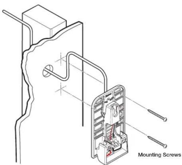
Locate the wall stud where the mounting plate will be installed and while positioning the mounting plate over the wall stud, mark the location of two pilot holes. Use the holes on either side of the mounting plate so that the stud does not interfere with the speaker wire routing, as shown below.
NOTE: A speaker wire access hole (see below) must also be cut in the wall, so mark that hole location now with the mounting plate positioned on the wall, while ensuring that the wall stud does not interfere with the wire routing and that the mounting plate hides the access hole.
-
Drill the mounting plate pilot holes and cut the speaker wire access hole, as previously marked.
-
Route the speaker cables through the wall without snagging, being sure to leave enough slack to connect the wires to the mounting plate.
Wiring the Speaker Mounting Plate
NOTE: Mounting hardware is not provided.
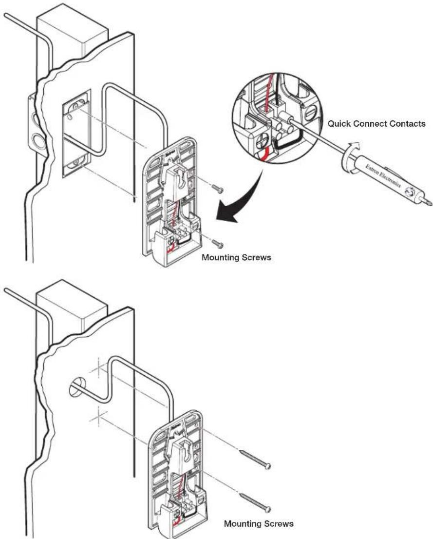
- Route the two speaker wires through the rear of the mounting plate and attach the wire ends to the quick connect contacts using a small screwdriver (see the illustration below). Be sure to observe the correct polarity.
NOTE: The positive (+) connector and the negative (-) connector are marked on the mounting plate.
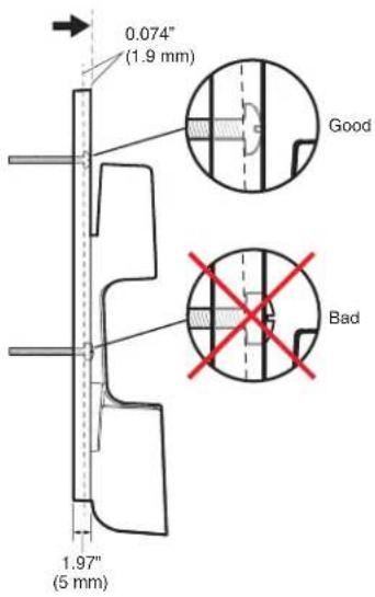
ATTENTION: Use the appropriate mounting screws. The screw heads must not protrude more than .074" (1.9 mm) above the screw holes in the mounting plate. If the screw head protrudes too far above the mounting plate surface, damage to the speaker may occur when the speaker is attached (see the figure below).
- Attach the mounting plate to the wall, using two mounting screws (see the illustrations below).
NOTE: The mounting screw holes in the mounting plate allow for some degree of play and lateral movement so that the mounting screws may be aligned properly with the screw holes of the wall box.
ATTENTION: Make sure that the wall box is secured to the wall structure and can handle the weight of the speaker. If there is doubt, secure the mounting plate with additional mounting screws. The wall stud mounting holes can be used for this purpose.
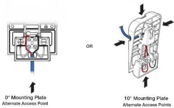
NOTE: When mounting to surfaces that do not allow wires to be routed from behind (such as on masonry or concrete walls) and the wires are routed to the speakers via a raceway, use the alternate access points to run the wires to the quick connect speaker contacts (see the figures below).
Attaching the Speaker to the Mounting Plate
Step 1: Attaching the Speaker
NOTE: If a secondary attachment point is being used, see the "Attaching a Secondary Support Cable" section on page 12 for installation details before proceeding further.
ATTENTION: By default, the SM 3 speaker is shipped unlocked. When mounting the speaker to the mounting plate, be sure that the speaker is unlocked. Failure to place the speaker in the unlocked position will result in damage to the speaker lock mechanism should an attempt be made to mount a locked speaker (see "Step 2: Using the Security Key to Lock and Unlock the Speaker" on page 10).
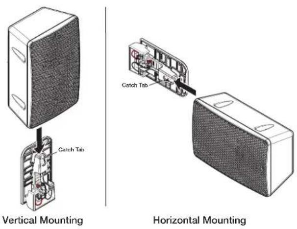
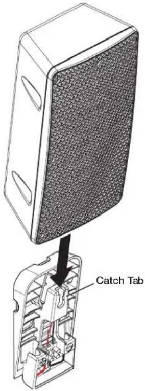
Position the rear mounting slot of the speaker above the catch tab of the mounting plate, then slide the speaker down into the mounting plate until a click is heard indicating that the speaker is secured in place (see figure below). When properly seated, the speaker connections are automatically made. Horizontal mounting is similar with only the orientation of the speaker being different.
Step 2: Using the Security Key to Lock and Unlock the Speaker
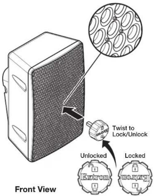
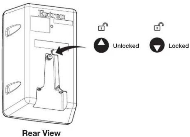
The SM 3 speaker uses an included security key to lock and unlock the speaker to its mounting plate (see the illustration below). The key has two positions: lock and unlock. The active position of the key is nearest the top of the speaker.
Insert the key into the center of the speaker grill and turn the key, as needed, so that the speaker is in the unlocked position (see the figure below). There are three small raised "dimples" on the grill surface that surround the keyhole. Repeat this procedure, but set the key to the locked position to lock the speaker.
CAUTION: The key must be rotated to the unlocked position before the speaker is attached to the mounting plate. Failure to place the speaker in the unlocked position will result in damage to the speaker lock mechanism should an attempt be made to mount the speaker.
NOTE: To avoid misplacing the key, store the key in a secure location for future use.
Removing the Speaker from the Mounting Plate
To remove the speaker from the mounting plate, you must unlatch the locking mechanism:
- Insert the security key into the keyhole of the speaker grill (see "Step 2: Using the Security Key to Lock and Unlock the Speaker" on page 10) and turn the key to the unlock position.
- Remove the security key.
- Apply pressure with your finger over the keyhole to unlatch the speaker from the mounting plate while lifting up on the speaker (see the illustration below).
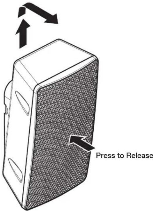
CAUTION: To avoid damaging or scratching the grill finish, do not use tools or sharp instruments to depress the unlocking mechanism hidden behind the center of the grill.
Attaching a Secondary Support Cable
If a secondary support cable is being attached, use the included screw to attach a suitable cable to the screw hole, as shown below.

Reference only
Reference Information
The Reference Information section describes:
- Packaging
Packaging
Extron Warranty
Extron Electronics warrants this product against defects in materials and workmanship for a period of five years from the date of purchase. In the event of malfunction during the warranty period attributable directly to faulty workmanship and/or materials, Extron Electronics will, at its option, repair or replace said products or components, to whatever extent it shall deem necessary to restore said product to proper operating condition, provided that it is returned within the warranty period, with proof of purchase and description of malfunction to:
and Central America:
Extron Electronics
1230 South Lewis Street
Anaheim, CA 92805
U.S.A.
Japan:
Extron Electronics, Japan
Kyodo Building, 16 Ichibancho
Chiyoda-ku, Tokyo 102-0082
Japan
Europe and Africa:
Extron Europe
Hanzeboulevard 10
3825 PH Amersfoort
The Netherlands
China:
Extron China
686 Ronghua Road
Songjiang District
Shanghai 201611
China
Asia:
Extron Asia Pte Ltd
135 Joo Seng Road, #04-01
PM Industrial Bldg.
Singapore 368363
Singapore
Middle East:
Extron Middle East
Dubai Airport Free Zone
F12, PO Box 293666
United Arab Emirates, Dubai
This Limited Warranty does not apply if the fault has been caused by misuse, improper handling care, electrical or mechanical abuse, abnormal operating conditions, or if modifications were made to the product that were not authorized by Extron.
NOTE: If a product is defective, please call Extron and ask for an Application Engineer to receive an RA (Return Authorization) number. This will begin the repair process.
USA: 714.491.1500 or 800.633.9876
Asia: 65.6383.4400
Europe: 31.33.453.4040
Japan: 81.3.3511.7655
Units must be returned insured, with shipping charges prepaid. If not insured, you assume the risk of loss or damage during shipment. Returned units must include the serial number and a description of the problem, as well as the name of the person to contact in case there are any questions.
Extron Electronics makes no further warranties either expressed or implied with respect to the product and its quality, performance, merchantability, or fitness for any particular use. In no event will Extron Electronics be liable for direct, indirect, or consequential damages resulting from any defect in this product even if Extron Electronics has been advised of such damage.
Please note that laws vary from state to state and country to country, and that some provisions of this warranty may not apply to you.
| Extron Headquarters+1.800.633.9876 (Inside USA/Canada Only)Extron USA - West Extron USA - East+1.714.491.1500 +1.919.850.1000+1.714.491.1517 FAX +1.919.850.1001 FAX | Extron Europe+800.3987.6673(Inside Europe Only)+31.33.453.4040+31.33.453.4050 FAX | Extron Asia+65.6383.4400+65.6383.4664 FAX | Extron Japan+81.3.3511.7655+81.3.3511.7656 FAX | Extron China+86.21.3760.1568+86.21.3760.1566 FAX | Extron Middle East+971.4.299.1800+971.4.299.1880 FAX | Extron Korea+82.2.3444.1571+82.2.3444.1575 FAX | Extron India1800.3070.3777(Inside India Only)+91.80.3055.3777+91.80.3055.3737 FAX |
- Safety Instructions
- Safety Instructions • English
- Chinese Traditional (繁體中文)
- Conventions Used in this Guide
- Notifications
- Specifications Availability
- Copyright
- Trademarks
- Contents
- Introduction.... 1
- Installation....3
- Reference Information 13
- Introduction
- About the SM 3 Speaker
- Features
- Application Example
- Installation
- Installing the Speaker Mounting Plate
- Mounting to a Wall Box
- Mounting to a Wall Stud
- Wiring the Speaker Mounting Plate
- Attaching the Speaker to the Mounting Plate
- Step 1: Attaching the Speaker
- Step 2: Using the Security Key to Lock and Unlock the Speaker
- Removing the Speaker from the Mounting Plate
- Attaching a Secondary Support Cable
- Reference Information
- Packaging
- Extron Warranty
- Japan:
- Europe and Africa:
- China:
- Asia:
- Middle East:
Brand : Extron
Model : SM 3
Category : Speaker