VT-81011 - Motion detector V-TAC - Free user manual and instructions
Find the device manual for free VT-81011 V-TAC in PDF.

User questions about VT-81011 V-TAC
0 question about this device. Answer the ones you know or ask your own.
Ask a new question about this device
Download the instructions for your Motion detector in PDF format for free! Find your manual VT-81011 - V-TAC and take your electronic device back in hand. On this page are published all the documents necessary for the use of your device. VT-81011 by V-TAC.
USER MANUAL VT-81011 V-TAC
WEEE Number: 80133970
INSTRUCTION MANUAL
INFRARED MOTION SENSOR
TECHNICAL DATA
| MODEL VT-81011 | |
| SKU 23427 | |
| INPUT VOLTAGE AC: 220-240V, 50/60 Hz | |
| RATED LOAD | Max. 800W 400W +LED |
| TIME DELAY | Min. 10sec ±3secMax. 15min ±2min |
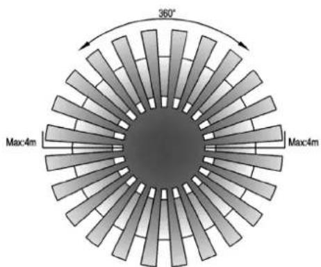
| DETECTION RANGE | 360° |
| DETECTION DISTANCE | 8m Max (<24°C) |
| DETECTION MOTION SPEED | 0.6-1.5m/s |
| WORKING TEMPERATURE | -20°C to +40°C |
| WORKING HUMIDITY | <93%RH |
| POWER CONSUMPTION | Approx, 0.9W |
| IP RATING IP20 | |
natural_image
Circular white ceiling lamp with concentric rings and central recess (no text or symbols)

| AMBIENT LIGHT <3-2000 LUX (Adjustable) | |
| INSTALLATION HEIGHT | 2.2-4m |
| DIMENSION | ∅102x24.9 mm |
INTRODUCTION & WARRANTY
Thank you for selecting and buying V-TAC product. V-TAC will serve you the best. Please read these instructions carefully before starting the installation and keep this manual handy for future reference. If you have any another query, please contact our dealer or local vendor from whom you have purchased the product. They are trained and ready to serve you at the best. The warranty is valid for 5 years from the date of purchase. The warranty does not apply to damage caused by incorrect installation or abnormal wear and tear. The company gives no warranty against damage to any surface due to incorrect removal and installation of the product.
Caution, risk of electric shock.

MULTI-LANGUAGE MANUAL QR CODE Please scan the QR code to access the manual in multiple languages.
This marking indicates that this product should not be disposed of with other household wastes.


- Please make sure to turn off the power before starting the installation.
- Installation must be performed by a qualified electrician.
- Cover or shied any adjacent live components.
- For indoor use only.
FUNCTION
- Can identify day and night: The consumer can adjust working state in different ambient light. It can work in the daytime and at night when it is adjusted on the "sun" position (max). It can work in the ambient light less than 3LUX when it is adjusted on the "3" position (min). As for the adjustment pattern, please refer to the testing pattern.
- Time-Delay is added continually: When it receives the second induction signals within the first induction, it will restart to time from the moment.
natural_image
Diagram showing red radial bars radiating from a circular structure with an arrow indicating direction (no text or symbols)
natural_image
Abstract black-and-white radial pattern with no text or symbols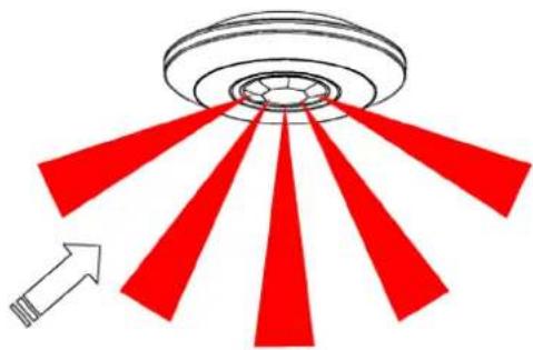
natural_image
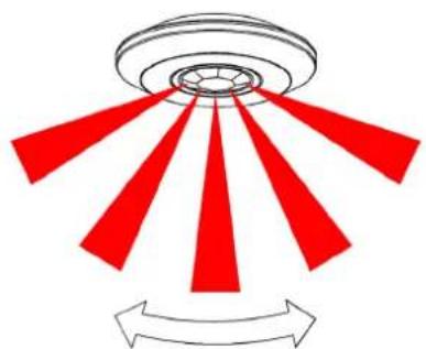
Diagram showing red arrows pointing outward from a circular structure, with an arrow indicating direction (no text or symbols)Good Sensitivity Poor Sensitivity
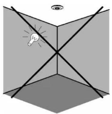
INSTALLATION ADVICE
As the detector responds to changes in temperature, avoid the following situations:
- Avoid pointing the detector towards objects with highly reflective surfaces, such as mirrors etc.
- Avoid mounting the detector near heat sources, such as heating vents, air conditioning units, light etc.
- Avoid pointing the detector towards objects that may move in the wind, such as curtains, tall plants etc.
natural_image
Diagram showing a light bulb inside a cube with diagonal lines, no text or symbols present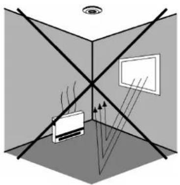
natural_image
Diagram of a 3D room with lighting sources and screens, no text or symbols present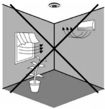
natural_image
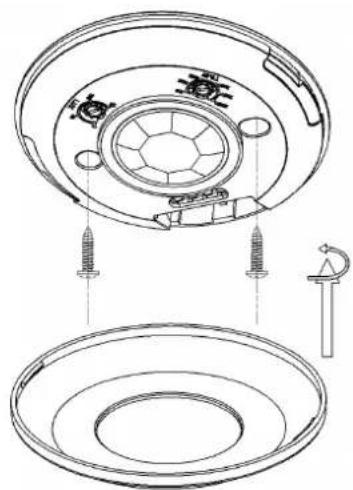
Diagram showing a potted plant under a ceiling with sunlight filtering through a window and ceiling-mounted screens (no text or symbols)INSTALLATION
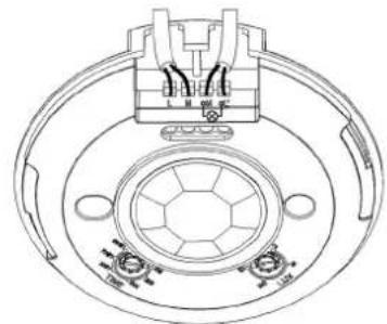
- Please move the upper cover with anti-clockwise whirl as per the diagram on the right.
- Connect the power and the load according to the connection-wire diagram.
- Fix the bottom on the selected position with the inflated screw.
• Install back the upper cover on the sensor, then you could switch on the power and test it.
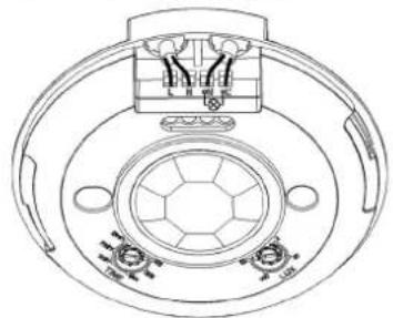
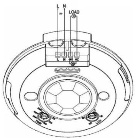
WIRING DIAGRAM
natural_image
Technical line drawing of a circular mechanical component with internal components and mounting holes (no text or symbols)The wires come in and out from the bottom
natural_image
Technical line drawing of a mechanical component with concentric rings and mounting holes (no text or symbols)The wires come in and out from the side
SENSOR INFORMATION
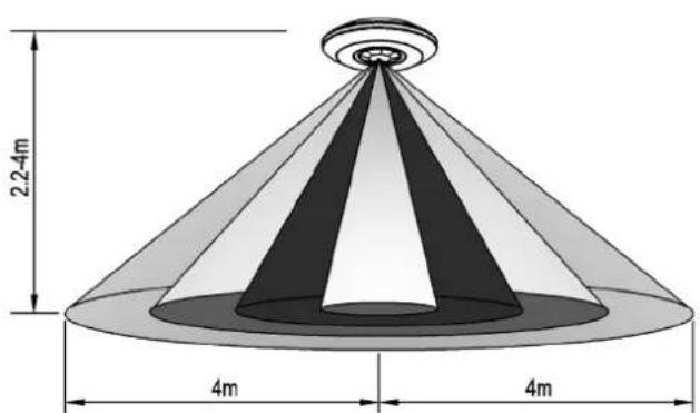
Height of Installation: 2.2-4m DETECTION DISTANCE: Max. 8m
TEST
- Turn the TIME knob anti-clockwise on the minimum (10s).Turn the LUX knob clockwise on the maximum (sun).
- Switch on the power; the sensor and its connected lamp will have no signal at the beginning. After Warm-up 30sec, the sensor can start work. If the sensor receives the induction signal, the lamp will turn on. While there is no another induction signal
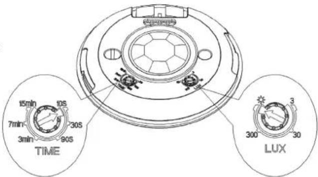
any more, the load should stop working within 10sec±3sec and the lamp would turn off.
- Turn LUX knob anti-clockwise on the minimum (3). If the ambient light is more than 3LUX, the sensor would not work and the lamp stop working too. If the ambient light is less than 3LUX (darkness), the sensor would work. Under no induction signal condition, the sensor should stop working within 10sec±3sec.
Note: when testing in daylight, please turn LUX knob to ⚙ (SUN) position, Otherwise the sensor lamp will not work. If the lamp is more than 60W, the distance between lamp and sensor should be 60cm at least.
TROUBLESHOOTING
• The load does not work:
a. Please check if the connection of power source and load is correct.
b. Please check if the load is good.
c. Please check if the settings of working light correspond to ambient light.
• The sensitivity is poor:
a. Please check if there is any hindrance in front of the detector to affect it to receive the signals.
b. Please check if the ambient temperature is too high.
c. Please check if the induction signal source is in the detection field.
d. Please check if the installation height corresponds to the height required in the instruction.
e. Please check if the moving orientation is correct.
• The sensor can not shut off the load automatically:
a. Please check if there is continual signal in the detection field.
b. Please check if the time delay is set to the maximum position.
RoHS