C1000 mPOS - Cash register Colormetrics - Free user manual and instructions
Find the device manual for free C1000 mPOS Colormetrics in PDF.

| Product Type | Mobile Point of Sale (mPOS) Cash Register |
| Brand | Colormetrics |
| Model | C1000 mPOS |
| Display | 4.3-inch color touchscreen, 480x272 pixels |
| Connectivity | Wi-Fi 802.11 b/g/n, Bluetooth 4.0, USB Type-C |
| Power Supply | DC 5V/2A via USB-C power adapter |
| Battery | Built-in rechargeable Li-Ion, 3000 mAh, up to 8 hours operation |
| Dimensions (WxDxH) | 220 x 150 x 60 mm |
| Weight | 0.6 kg |
| Operating System | Android 10 (customized) |
| Processor | Quad-core ARM Cortex-A7, 1.5 GHz |
| Memory | 2 GB RAM, 16 GB internal storage |
| Supported Payment Methods | Credit/debit cards (EMV), NFC contactless, QR code |
| Integrated Printer | Thermal receipt printer, 58 mm paper width, up to 100 mm/s |
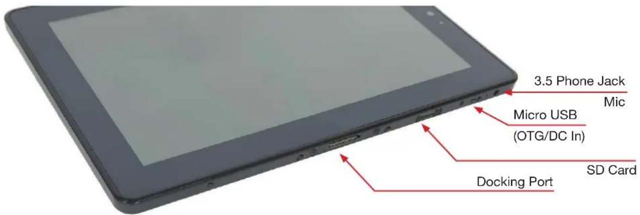
| Ports | 1x USB-C, 1x microSD slot, 1x 3.5mm audio jack |
| Accessories Included | Power adapter, USB-C cable, quick start guide, receipt paper roll |
| Maintenance | Clean with soft dry cloth; avoid liquids; do not use abrasive cleaners |
| Safety | CE, FCC, RoHS certified; overcharge protection; thermal cutoff |
| Spare Parts & Reparability | Battery and printer module replaceable; other components not user-serviceable |
| Environmental Conditions | Operating temperature: 0°C to 40°C; humidity: 20% to 80% non-condensing |
| Warranty | 1 year limited warranty |
Frequently Asked Questions - C1000 mPOS Colormetrics
User questions about C1000 mPOS Colormetrics
0 question about this device. Answer the ones you know or ask your own.
Ask a new question about this device
Download the instructions for your Cash register in PDF format for free! Find your manual C1000 mPOS - Colormetrics and take your electronic device back in hand. On this page are published all the documents necessary for the use of your device. C1000 mPOS by Colormetrics.
USER MANUAL C1000 mPOS Colormetrics
natural_image
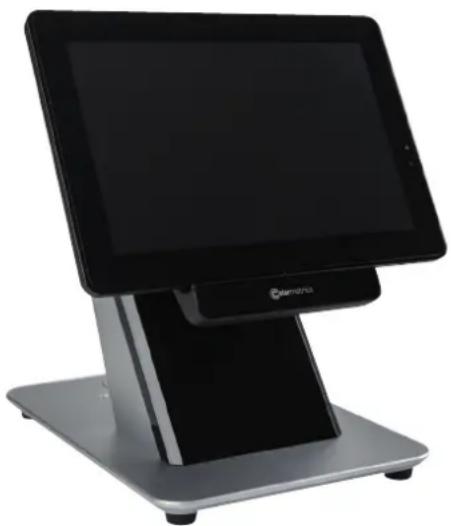
Exterior view of a modern tablet display stand with 'Colormetrics' branding (no additional text or symbols visible)COPYRIGHT
Copyright 2017 Publishing. All Rights Reserved.
This manual, software and firmware described in it are copyrighted by their respective owners and protected under the laws of the Universal Copyright Convention. You may not reproduce, transmit, transcribe, store in a retrieval system, or translate into any language, in any form or by any means, electronic, mechanical, magnetic, optical, chemical, biological, molecular, manual, or otherwise, any part of this publication without the express written permission of the publisher.
All products and trade names described within are mentioned for identification purpose only. No affiliation with or endorsement of the manufacturer is made or implied. Product names and brands appearing in this manual are registered trademarks of their respective companies.
The information published herein has been checked for accuracy as of publishing time. No representation or warranties regarding the fitness of this document for any use are made or implied by the publisher. We reserve the right to revise this document or make changes in the specifications of the product described therein at any time without notice and without obligation to notify any person of such revision or change.
SAFETY AND WARRANTY
- Read these safety instructions carefully.
- Disconnect the equipment from power outlet before cleaning, disassembly or transport. Do not use liquid or spray detergents for cleaning. Use a damp cloth only and avoid any prolonged contact with moisture.
- Keep the unit away from humidity.
- Place the unit on a sturdy surface before servicing or operation to prevent accidental drops.
- The openings on the enclosure are for ventilation. Do NOT cover the openings.
- Make sure the voltage and load ratings of the power source are correct before connecting the equipment to the power outlet.
- Position the power cord to prevent accidental tripping. Do not twist, pinch or clip the power cord.
- All cautions and warnings printed on the equipment should be followed.
- If the equipment is not used for a long time, disconnect it from the power source.
- Never pour any liquid into openings. This could cause fire or electrical shock.
- For safety reasons, only qualified service personnel should open and service the equipment.
- If any of the following situations arises, get the equipment checked by service personnel:
- The power cord, plug, or adapter is visibly damaged.
- Liquid has entered into the equipment.
- The equipment has been exposed to moisture.
- The equipment has been dropped and damaged.
-
The equipment has obvious signs of breakage.
-
DO NOT LEAVE THIS EQUIPMENT IN AN UNCONTROLLED ENVIRONMENT WHERE THE STORAGE TEMPERATURE IS BELOW -20 °C (-4 °F) OR ABOVE 60 °C (140 °F).
TABLE OF CONTENTS
CHAPTER 1
Introduction....2
Main features 4
C1000 mPOS packing list 4
C1000 mPOS 5
Expansion Cover 7
C1000 mPOS Docking Station 8
Tablet dimensions....9
Dimensions of tablet with Expansion Cover 10
Dimensions of tablet with Docking Station.... 11
Operation tilt angle & limitation.... 12
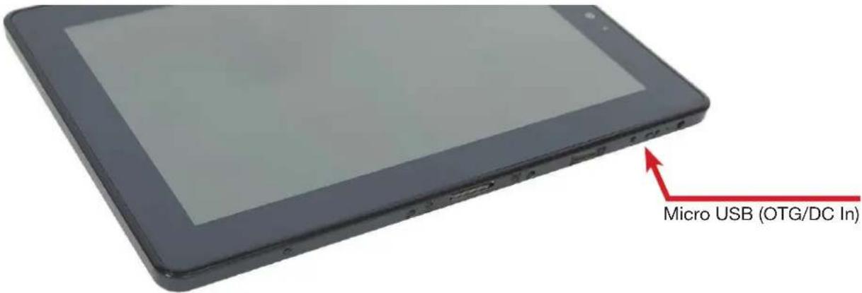
Rear I/O panel connectivity 13
CHAPTER 2
Hardware installation 15
Expansion Cover installation 15
Activate from shipping mode....16
Docking Station lock & release 17
Installation of a SIM card in the Expansion Cover 18
Cash drawer installation 20
Customer display Installation 21
COM port setting 24
CHAPTER 3
Software installation and setup 25
LTE module driver installation 26
CHAPTER 4
Specifications 30
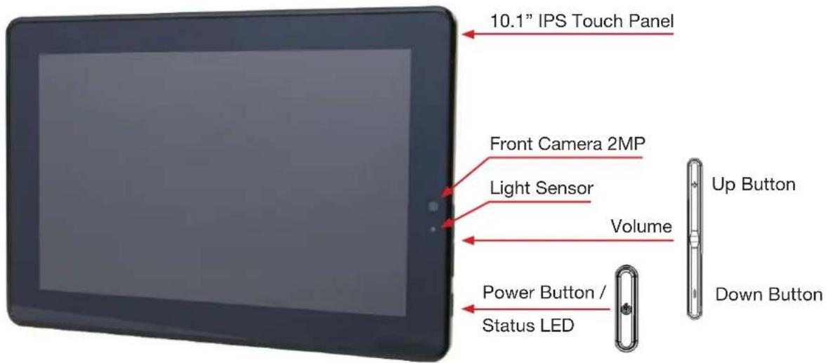
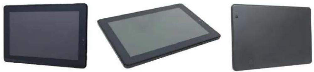
Main Features:
- Windows and Android compatible POS tablet
• Ruggedized for tough environments
• High-quality, durable tempered glass with P-Cap touch - With IP54-rating-compliant front panel and able to withstand drops of up to 1.2 m
- Variety of supported devices: EMV reader, MSR, NFC, camera, 1D/2D scanner, 4G LTE, MicroSD card slot
natural_image
Exterior view of a modern digital tablet stand (no visible text or symbols)C1000 mPOS packing list
| Standard Optional & Peripherals | |||
| 1 | 10.1” Tablet POS Terminal | 1 | RJ-45 to D-sub9 adapter cable |
| 2 | 5V 10W power adapter | 2 | Expansion Cover |
| 3 | Micro USB cable | 3 | Docking Station |
| 4 | Optional 2^nd I/O panel | ||
| 5 | 12V 60W/150W power adapter | ||
CHAPTER 1
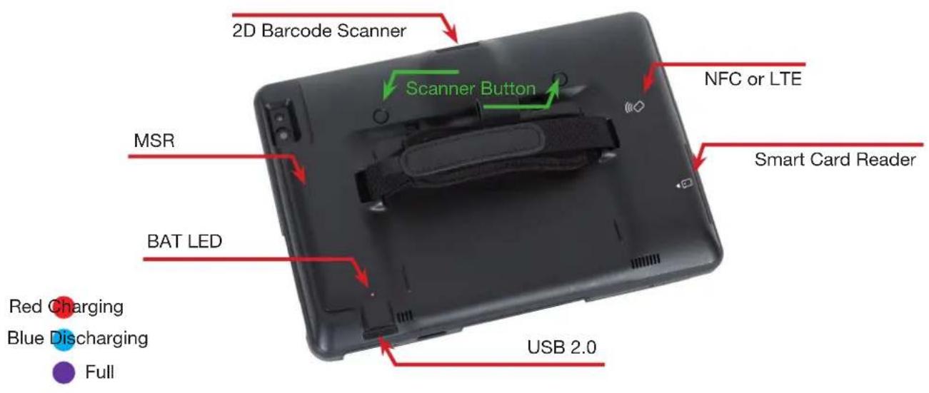
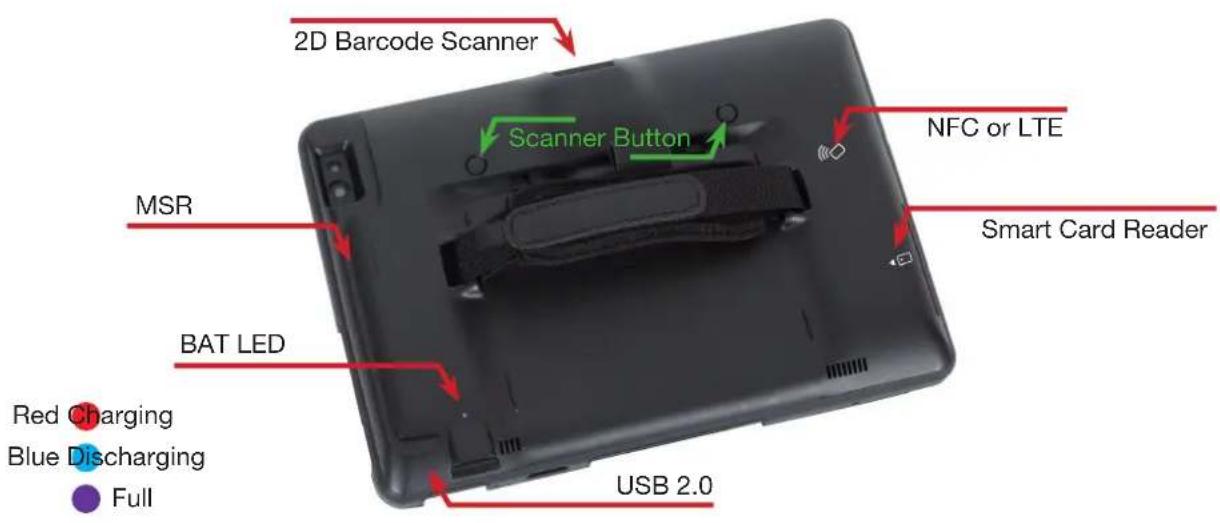
C1000 mPOS
LED STATUS Note
| RED | Battery charging | |
| BLUE | Battery discharging / System on | |
| PURPLE | Battery fully charged | |
| None | System off without charging / or Shipping Mode |
CHAPTER 1
CHAPTER 1
Expansion Cover
| LED STATUS Note | ||
| RED | 2^nd battery charging | |
| BLUE | 2^nd battery discharging Charging 1 | ^st battery |
| PURPLE | 2^nd battery fully charged | |
| None | 2^nd battery 0% / or Shipping Mode | |
CHAPTER 1
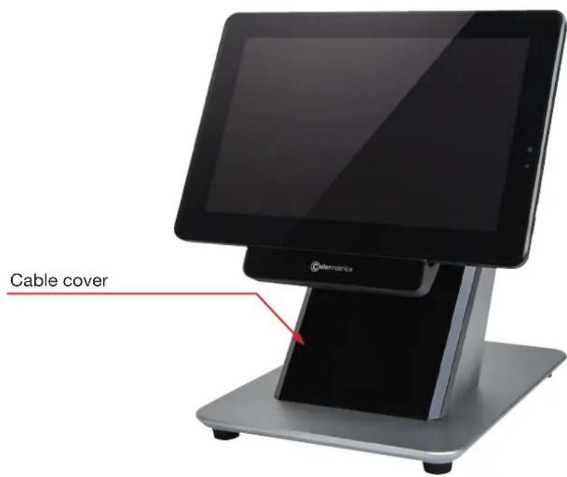
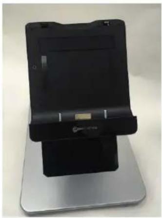
C1000 mPOS Docking Station (Option)
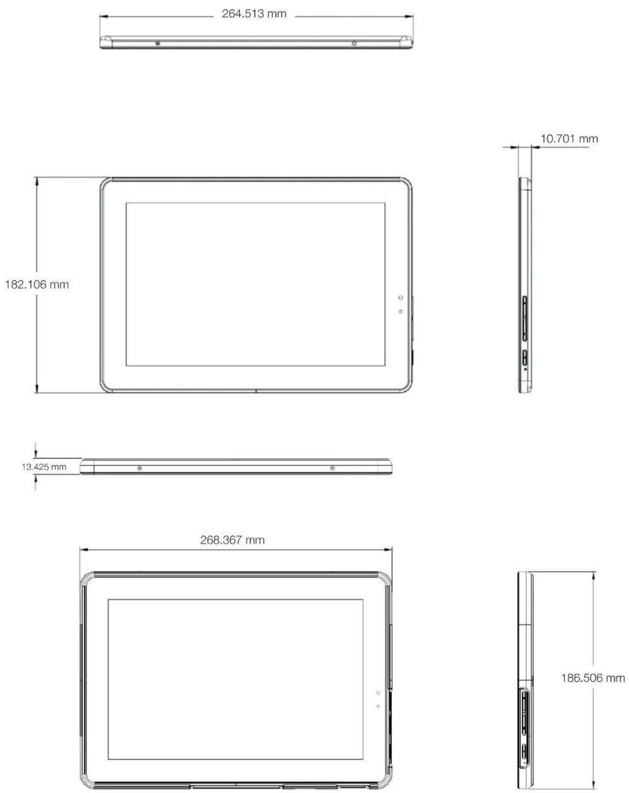
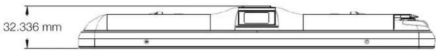
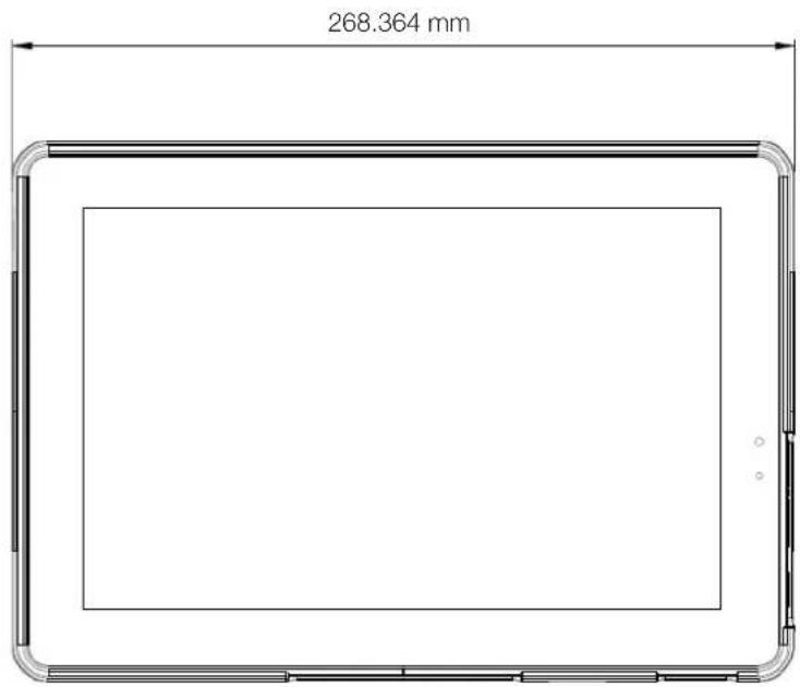
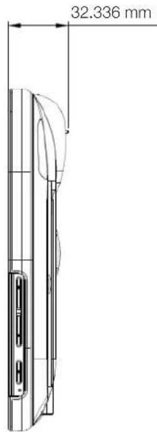
Tablet dimensions
CHAPTER 1
Dimensions of tablet with Expansion Cover
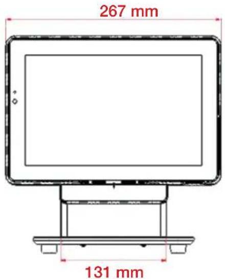
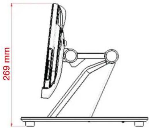
Dimensions of tablet with Docking Station
CHAPTER 1
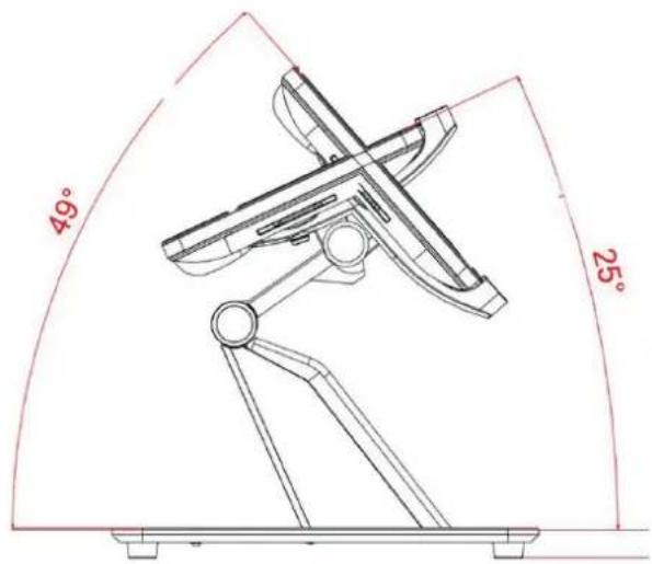
Operation tilt angle & limitation
Tilt angle: 96^ to 183^
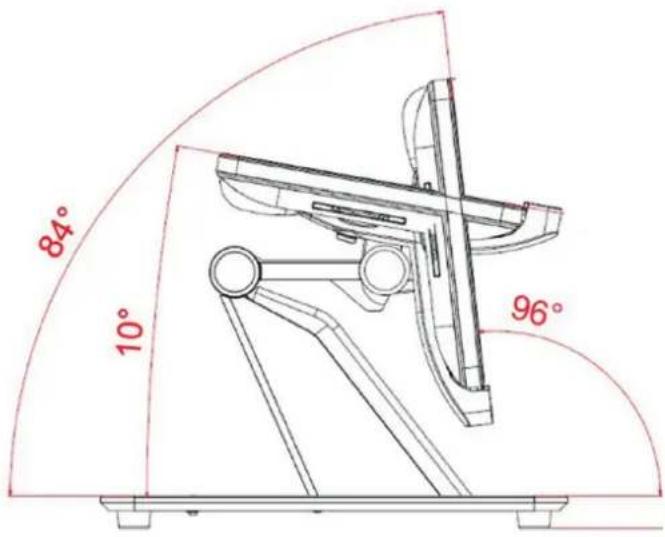
Lift angle: 35^
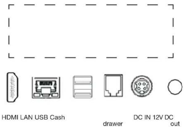
Rear I/O panel connectivity
Default I/O panel
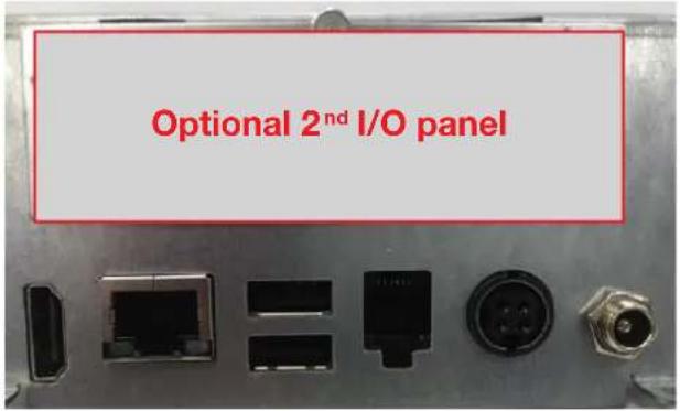
Optional 2 ^nd I/O panel
| 2^nd IO type | ||
| Type A | 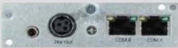 | 1*24V Out / 2*RJ45 COM Port |
| Type B | 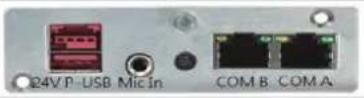 | 1*PUSB24V / 2*RJ45 COM Port |
| Type C | 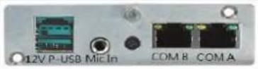 | 1*PUSB12V / 2*RJ45 COM Port |
| Type G | 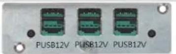 | 3*PUSB12V |
| Type H | 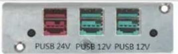 | 1*PUSB24V / 2*PUSB12V |
| I/O Port Connector Type Description | ||
| 12V DC out DC out 2.5 mm 12 V DC out for | 12V peripherals | |
| 12V DC in DC-in (4 pin) 12 V power adapter | ||
| Cash Drawer RJ-11 12 V cash drawer | ||
| USB USB Type A | USB 2.0 | |
| USB USB Type A | USB 2.0 / 3.0 | |
| Ethernet RJ-45 10/100 LAN | ||
| Video HDMI 2 | ^nd LCD | |
| Option Type A | ||
| 24V DC out DC-out (3 Pin) 24V DC Output | ||
| COM 5 | RJ-45 | Serial port COM 5 (select with jumper)RI-NA LED; 5V-Green Light; 12V - Orange Light |
| COM 6 | RJ-45 | Serial port COM 6 (select with jumper)RI-NA LED; 5V-Green Light; 12V - Orange Light |
| Option Type B | ||
| 24V USB 2.0 | 24V USB | 24V USB device |
| COM 5 | RJ-45 | Serial port COM 5 (select with jumper)RI-NA LED; 5V-Green Light; 12V - Orange Light |
| COM 6 | RJ-45 | Serial port COM 6 (select with jumper)RI-NA LED; 5V-Green Light; 12V - Orange Light |
| Option Type C | ||
| 12V USB 2.0 | 12V USB | 12V USB device |
| COM 5 | RJ-45 | Serial port COM 5 (select with jumper)RI-NA LED; 5V-Green Light; 12V - Orange Light |
| COM 6 | RJ-45 | Serial port COM 6 (select with jumper)RI-NA LED; 5V-Green Light; 12V - Orange Light |
| Option Type G | ||
| 12V USB 2.0 *3 | 12V USB | 12V USB device |
| Option Type H | ||
| 24V USB 2.0 | 24V USB | 24V USB device |
| 12V USB 2.0 *2 | 12V USB | 12V USB device |
CHAPTER 2
Hardware installation
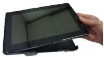
Expansion Cover Installation
- Turn off power and remove power cord from the terminal.
Put the tablet into the Expansion Cover.
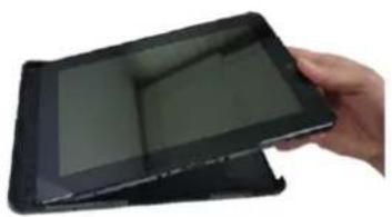
natural_image
Hand holding a black tablet device with visible screen (no text or symbols)Insert left side first.
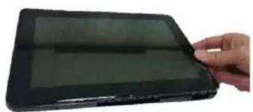
natural_image
Hand holding a black rectangular electronic device with a screen, no visible text or symbolsPress the tablet into position.
natural_image
Hand holding a black tablet device with a screen, no visible text or symbols on the device itself.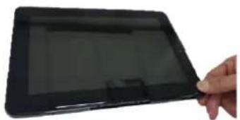
natural_image
Hand holding a black tablet device with a screen, no visible text or symbols on the device itself
natural_image
Close-up of hands holding a black tablet with a visible screen, no text or symbols presentFasten the 4 screws to fix the tablet and Expansion Cover.
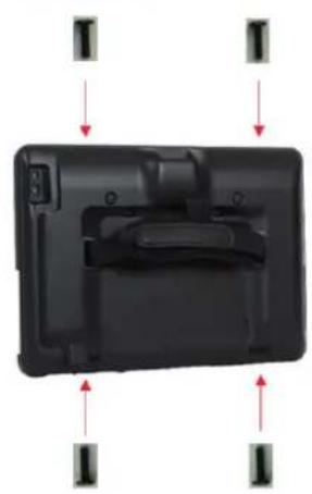
natural_image
Black plastic device with internal components and directional arrows indicating movement or orientation (no text or symbols)CHAPTER 2
Activate from shipping mode
Activate from shipping mode: Apply 5V DC voltage to Micro USB port.
CHAPTER 2
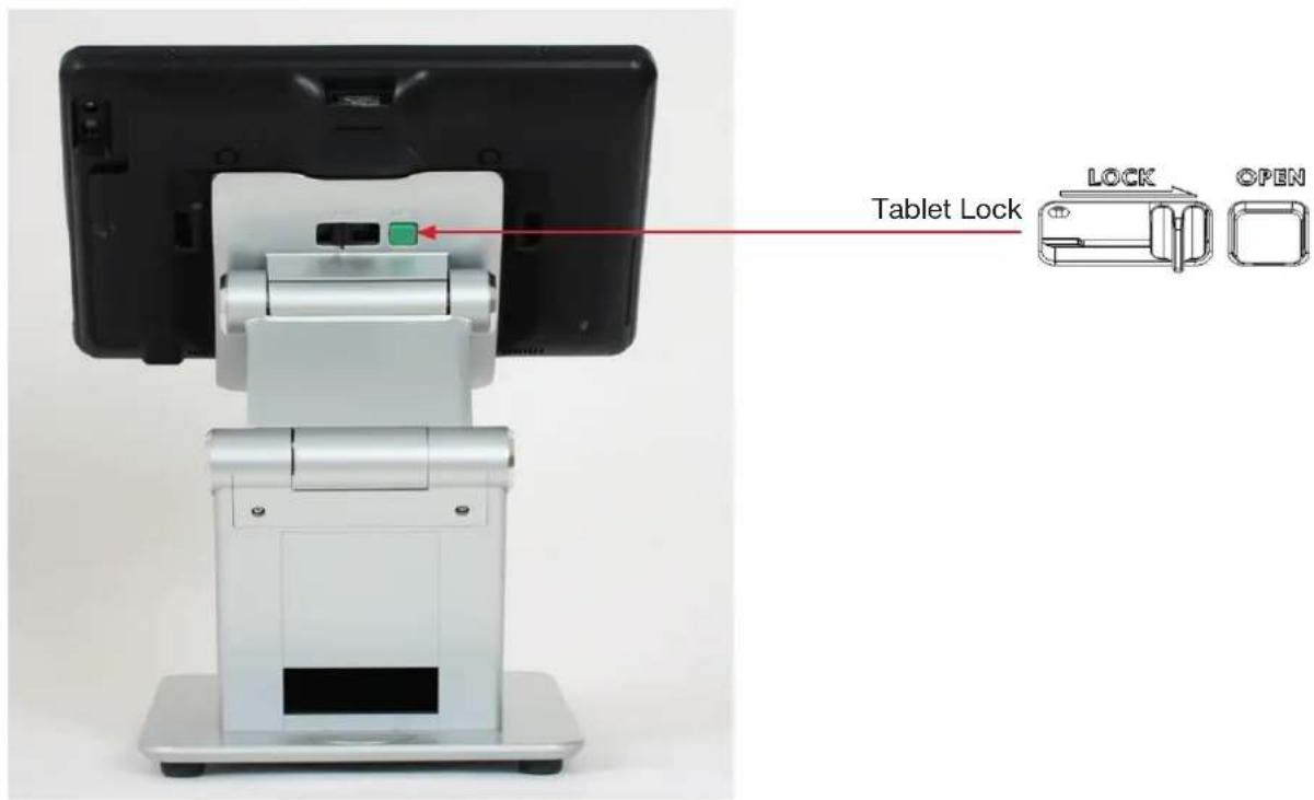
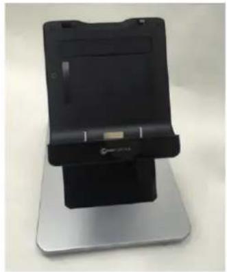
Docking Station lock & release
1. Lock Tablet
Step 1. Place the Docking Station on a stable surface.
natural_image
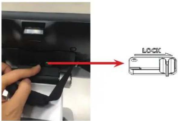
Black and silver electronic device with a stand (no visible text or symbols)Step 3. Push locker from left to right.
natural_image
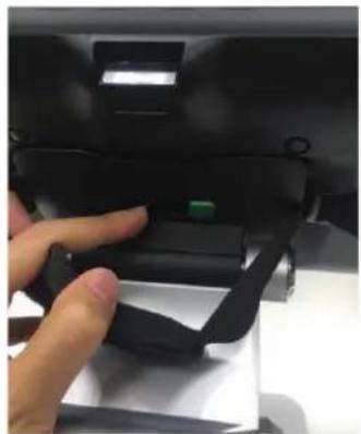
Close-up of a hand pressing a black mechanical component with a green indicator (no visible text or symbols)2. Unlock Tablet
Step 1. Push green button to unlock tablet. Step 2. Remove tablet.

natural_image
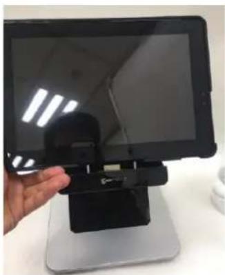
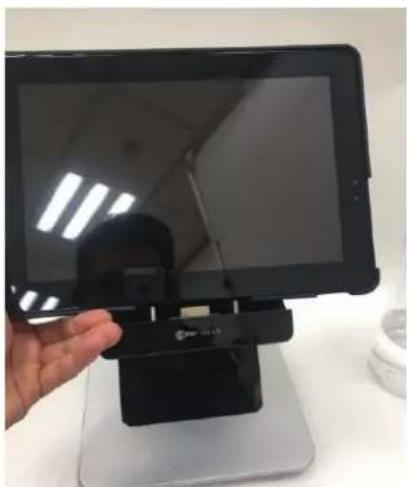
Close-up of a hand pressing a black mechanical component with a green button (no visible text or symbols)Step 2. Properly dock the tablet to the stand.
natural_image
Hand holding a black electronic device on a stand, no visible text or symbolsStep 4. Check that the lock position is as shown in the picture.
natural_image
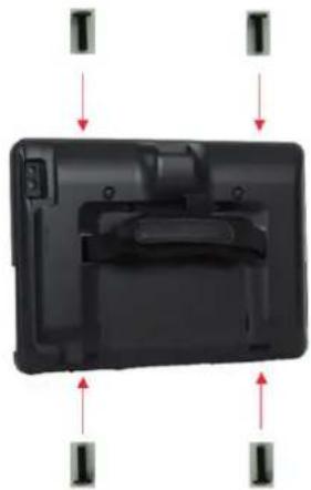
Hand holding a black tablet stand with a small device, placed on a silver base (no visible text or symbols)Installation of a SIM card in the Expansion Cover
- Remove 4 screws
natural_image
Black plastic electronic device with red directional arrows indicating orientation (no text or symbols)- Remove tablet (pull out)
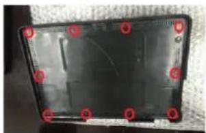
- Remove 10 screws in Expansion Cover
natural_image
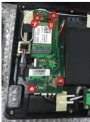
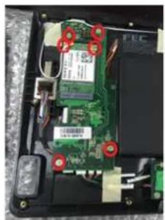
Black rectangular electronic device with red circular markers on the sides, no visible text or symbols- Remove 6 screws on PCB
natural_image
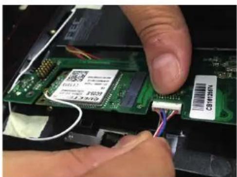
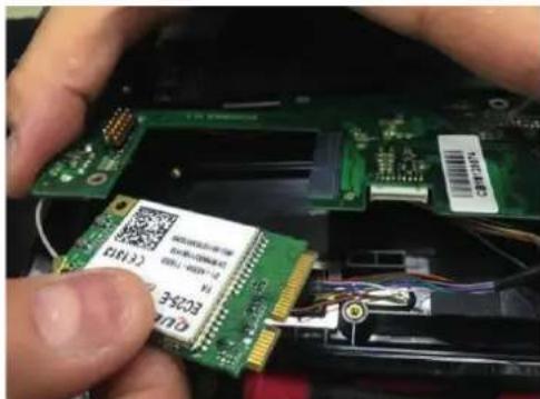
Interior view of an electronic circuit board with visible traces and components (no readable text or symbols)- Remove connector and module
natural_image
Close-up of hands installing a green circuit board with a USB cable and barcode tag (no readable text or symbols)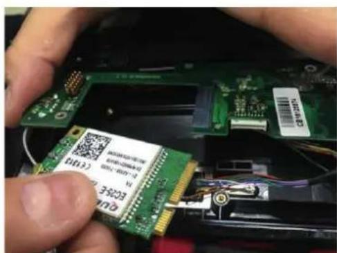
- Insert SIM card in slot
natural_image
Close-up of hands installing or adjusting a green printed circuit board with visible components (no text or symbols)- Put module back
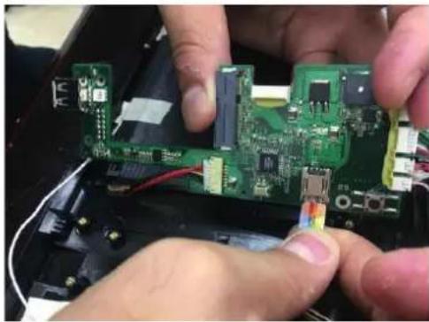
- Put connector back
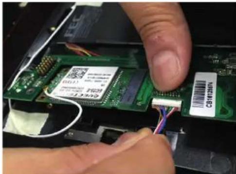
natural_image
Close-up of hands inserting a green electronic circuit board into a device (no visible text or symbols)- Fasten 6 screws for PCB & fasten 10 screws for Expansion Cover
natural_image
Interior view of an electronic circuit board with visible components and red circular annotations (no readable text or symbols)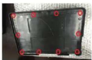
natural_image
Black plastic tray with red circular markers on the left face, no visible text or symbolsCHAPTER 2
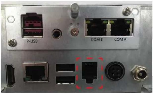
Cash drawer installation
Before connecting the cash drawer to the stand, please make sure the drive voltage and cable pin assignment of the cash drawer matches the definition of the cash drawer port.
natural_image
Front panel of a network device showing ports and connectors (no readable text or symbols)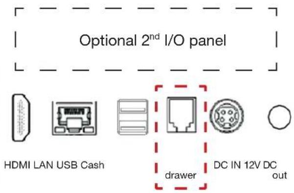
IO_BASE_ADDRESS = 0xfed80000;
R_PCH_CFIO_SOUTHWEST = 0x00;
R_PCH_CFIO_NORTH = 0x 8000
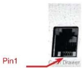
| Cash Drawer 1: DIO with RJ-11 connector | |
| PIN no. | Signal description |
| 1 Ground | |
| 2 DIO Out 1 | |
| 3 +12V | |
| 4 DIO IN 0 | |
| 5 DIO Out 0 | |
| 6 Ground | |
CHAPTER 2
Customer display Installation
- Assemble pole type customer play module
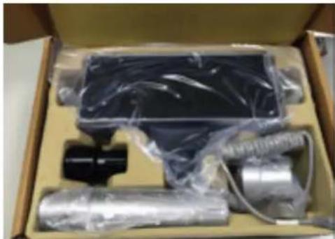
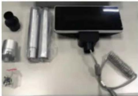
Open Customer display package.
natural_image
Box containing various electronic components including a rectangular device, coiled tubing, and a black connector (no visible text or symbols)Content: VFD x 1, Pole x 2 RJ45 to RJ45 cable, Aluminum stand x 1, black plastic x 1, Screw x 8
natural_image
White lab desk with electronic components including batteries, a charging device, and a coiled cable (no visible text or symbols)Assemble pole

natural_image
Close-up of a handheld electronic device with a black connector and a small cylindrical component, placed on a white surface (no visible text or symbols)4 Screw for Aluminum Stand
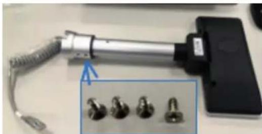
natural_image
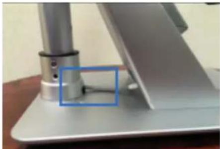
Close-up of a handheld electronic device with coiled cable and four metallic screws, no visible text or symbols.- Assemble pole type customer play module with Main unit Remove cable cover from Main unit stand
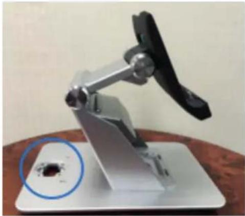
natural_image
Mechanical device with a circular inset showing a dark spot on its surface (no text or symbols visible)put cable into main unit
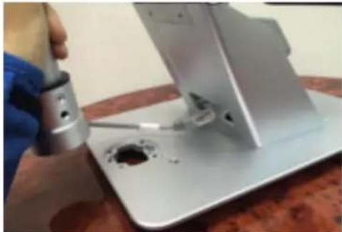
natural_image
Close-up of a hand using a tool to adjust or install a metal mechanical component with a hole (no visible text or symbols)Make sure pole install in the correct position.
natural_image
Close-up of a metallic electronic device with a blue highlighted component, no visible text or symbols4 Screw for the Main unit fix pole module

natural_image
Close-up of a mechanical component with bolts and a yellow cable inserted (no visible text or symbols)CHAPTER 2
Connect RJ45 cable with stand Interface.
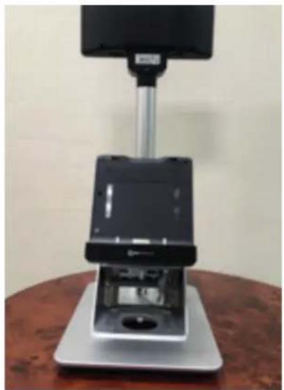
natural_image
Exterior view of a modern office building (no signage)CHAPTER 2
COM port setting
This section showing
- COM port position.
- How to adjust voltage RI or 5V or 12V by jumper on the PCB board.
- Mode setting.
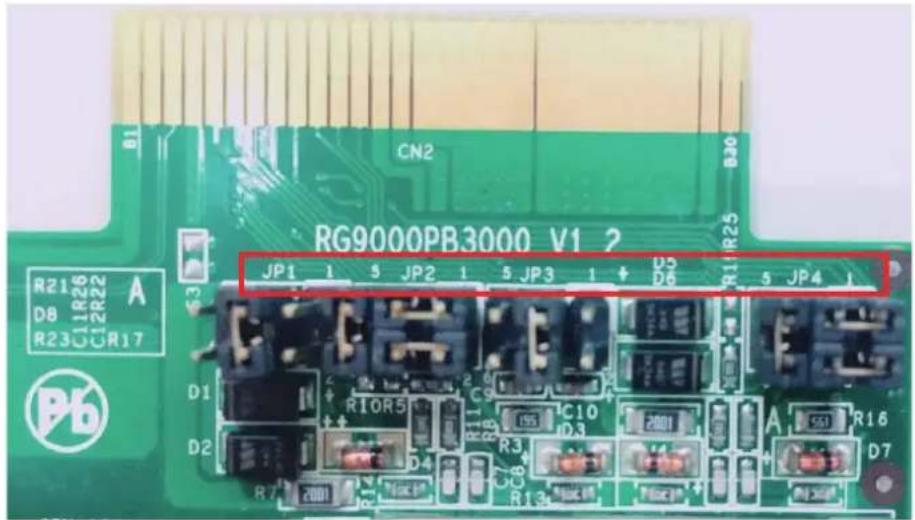
Comport position:
Adjust voltage & Mode setting
Example Type C option IO:
JP1 & JP2 are for COM6 setting
JP3 & JP4 are for COM5 setting
To adjust COM6 voltage set as 12V. (Put jumper on JP1, short pin 5 & 6) To set COM6 as VFD mode (Put jumper on JP2, short pin 1&2, 3&5, 4&6)
Software installation and setup
Chipset Driver Installation
Intel Chipset Installation Utilities for Windows 10
- Copy the drivers.zip file to your device, and unzip it.
- Right click install.bat file, select "Run as administrator" to install the drivers.

- After the drivers install completely, then right click Disable_bdg.bat file, select "Run as administrator" to run it.

- After run completely, restart the device.
LTE module driver installation
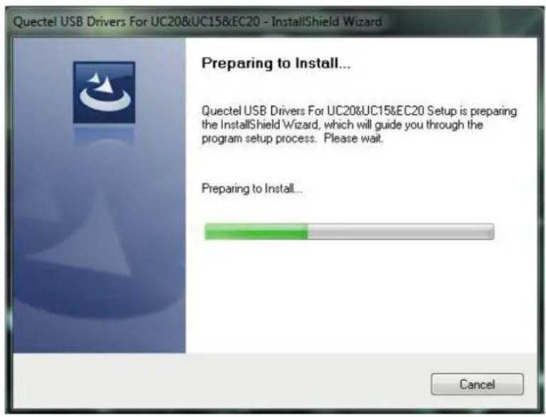
- The image below shows that the system has not installed the driver.
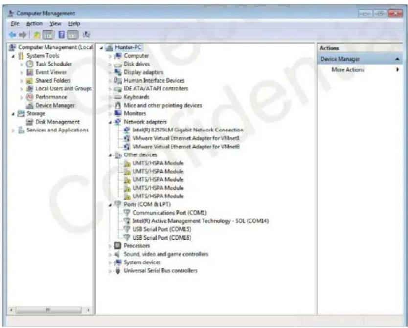
Image 1: Driver not installed for EC25-E module
Note: You must ensure the EC25 module has been connected to the unit before installing the drivers.
- Check installation setting.
Note: Please get the latest installation package.
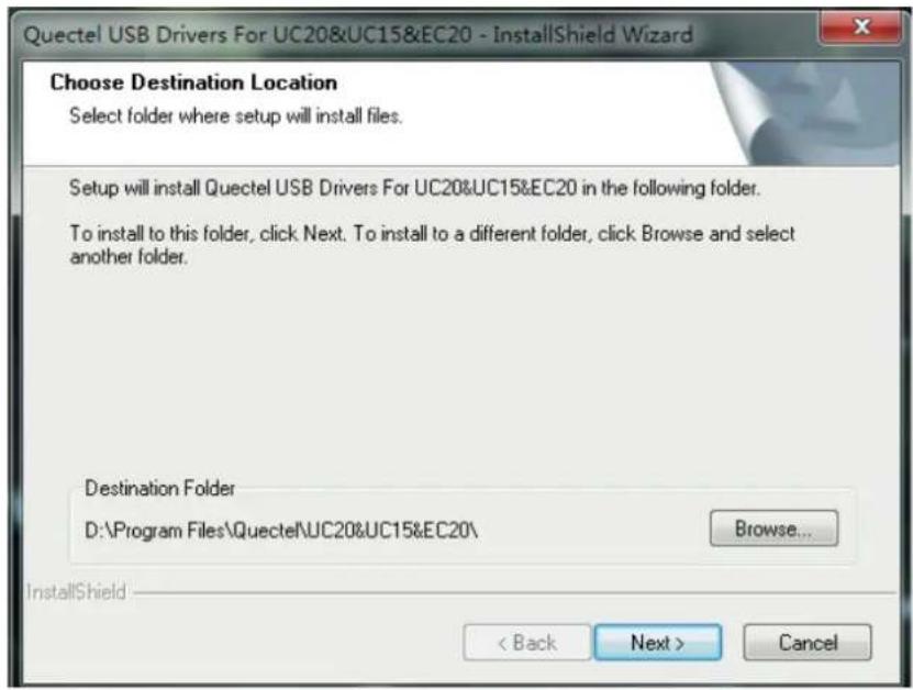
3. Choose destination location
If you do not want to change the default location, please click "Next" directly to go on.
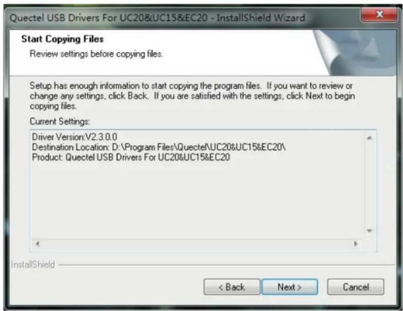
4. Prepare driver files needed for installation.
Click "Next" to go on, as shown below.
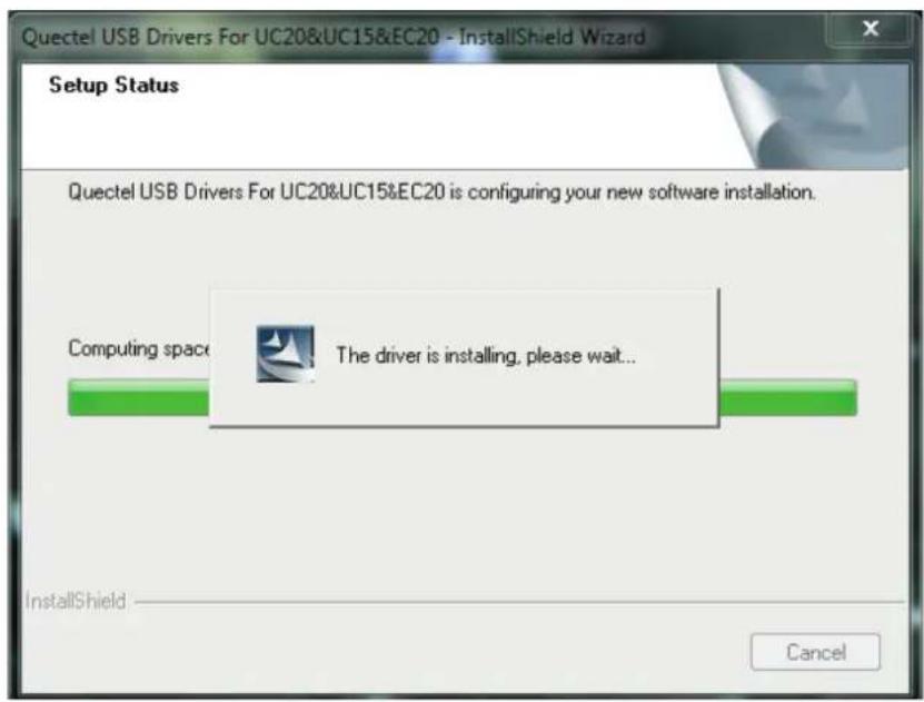
5. Automatic installation
It may take some time to install the drivers, please wait patiently for the process to complete.
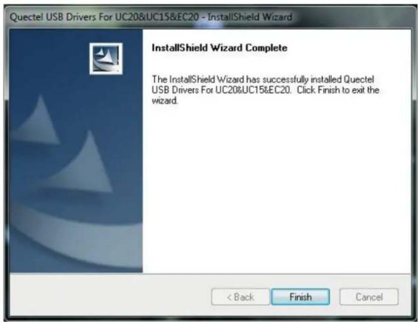
6. Complete Installation
The drivers have been installed completely, shown as below.
Specifications
| Specifications | |
| Screen | 10.1" IPS, 1280x800, 350 nits, 25K |
| Touch | Projected Capacitive (Multi-touch) |
| Processor | Intel Cherry Trail Quad Core Atom X5 Z8300 1.44 GHz ~ 1.84 GHz |
| OS | Windows 10, Android 5.1 |
| Built-in Storage | eMMC 64G (Windows), eMMC 32G (Android) |
| 2nd Storage | Micro SD Card Slot (max.: 128 GB) |
| Memory | LP DDR3 4G (Windows), LP DDR3 2G (Android) |
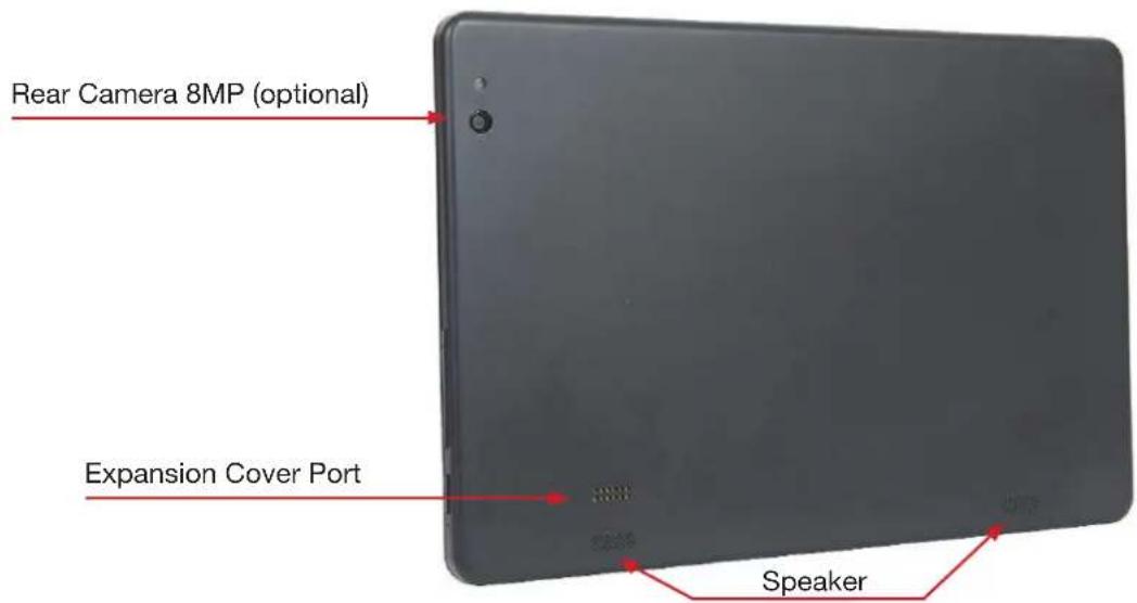
| Camera | Front camera: 2 MP (default),Rear camera: 8 MP (optional) |
| Connection | Wifi 802.11 b/g/n, Bluetooth 4.0 |
| Battery | Non-Removable 6800 mAh Li-on |
| Sensor | Accelerator-sensor / Gyroscope / Light sensor |
| Line out | 3.5 mm phone jack |
| Micro USB | DC in |
| Mic In | DMIC |
| Speakers | 1W x 2 Speakers |
| Size & Weight | 264.5 mm x 182 mm x 10.7 mm; 678 g |
| Specifications | |
| Protection | Drop specs. 1.2 m |
| Add-on Options | MSR (ISO T1/2/3) |
| 1D/2D scanner | |
| IC card reader | |
| NFC Reader/Writer | |
| Battery 6800 mAh | |
| 1 x USB 2.0 port | |
| 4G LTE module | |
| Size & Weight | 268 mm x 187 mm x 32.3 mm, 458 g (depends on add-on devices) |
| Expansion Cover with peripheral options (max. 3 items), 1 x USB 2.0 port (NFC, IC card reader and 4G LTE antenna share the same USB port and position, cannot co-exist). | |
natural_image
Black and silver electronic device with a stand, no visible text or symbols on the device itself.| Specifications | |
| Default I/O panel | HDMI |
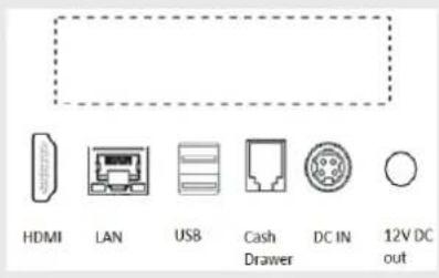 | LAN port |
| USB 2.0 x 2 | |
| Cash drawer (RJ-11) | |
| DC 12V in | |
| DC 12V out | |
| Power Adapter | 12V 60W / 12V 150W (with 2^nd I/O) |
| Optional I/O panel | Type A / B / C / G / H |
- COPYRIGHT
- Copyright 2017 Publishing. All Rights Reserved.
- SAFETY AND WARRANTY
- TABLE OF CONTENTS
- CHAPTER 1
- CHAPTER 2
- CHAPTER 3
- CHAPTER 4
- Main Features:
- Expansion Cover
- Operation tilt angle & limitation
- Rear I/O panel connectivity
- Hardware installation
- Expansion Cover Installation
- Activate from shipping mode
- Docking Station lock & release
- Lock Tablet
- Unlock Tablet
- Installation of a SIM card in the Expansion Cover
- Cash drawer installation
- Customer display Installation
- COM port setting
- Adjust voltage & Mode setting
- Software installation and setup
- Chipset Driver Installation
- LTE module driver installation
- Choose destination location
- Prepare driver files needed for installation.
- Automatic installation
- Complete Installation
Brand : Colormetrics
Model : C1000 mPOS
Category : Cash register