P2300 - Cash register Colormetrics - Free user manual and instructions
Find the device manual for free P2300 Colormetrics in PDF.

| Product Type | Electronic Cash Register |
| Model | P2300 |
| Brand | Colormetrics |
| Dimensions (approx.) | 350 x 300 x 150 mm |
| Weight (approx.) | 3.5 kg |
| Power Supply | AC adapter (9V DC, 1A) |
| Display | Backlit LCD, operator and customer |
| Printer | Thermal receipt printer, 58mm paper roll |
| Key Functions | PLU, department keys, tax keys, payment modes (cash, card, check) |
| Memory | Up to 3000 PLUs, 200 clerks |
| Connectivity | RS-232 port for PC or printer |
| Battery Backup | Internal battery for memory retention |
| Maintenance | Clean exterior with soft dry cloth; avoid liquids |
| Safety | Keep away from water and extreme temperatures; unplug during storms |
| Spare Parts | Thermal paper rolls (58mm), printer head |
| Repairability | Contact authorized service center for repairs |
| Manual | User manual available for download (92 pages, English) |
Frequently Asked Questions - P2300 Colormetrics
User questions about P2300 Colormetrics
0 question about this device. Answer the ones you know or ask your own.
Ask a new question about this device
Download the instructions for your Cash register in PDF format for free! Find your manual P2300 - Colormetrics and take your electronic device back in hand. On this page are published all the documents necessary for the use of your device. P2300 by Colormetrics.
USER MANUAL P2300 Colormetrics
natural_image
Two modern digital display units with black covers and a white base, no visible text or symbols on the devices themselves.Table of ConTenTs
CopyrightT 4
safeTy insTruCTions 5
paCking lisT 6
1-1. Standard Accessories 6
sysTem View 7
2-1. Rear View with Optional LPT Port 7
2-2. Specification 8
2-3. Internal Layout 9
pin Definition 11
rear i/o inTerfaCe 13
sysTem assembly & Disassembly 15
3-1. HDD 15
3-2. CF- Card 15
3-3. MSR 17
3-4. Cable Cover 17
3-5. 15" 2nd Display 18
3-6. 8" 2nd Display 21
3-7. 1D / 2D / iButton with RFID Module 25
DeViCe DriVer insTallaTion 26
4-1. Resistive Type Touch Panel 26
4-2. MagStripe Card Reader Configuration Utility 33
4-3. Fingerprint Reader 37
4-4. RFID 48
inTernal VfD (opTional) 58
5-1. VFD Specification 58
seTup softWare guiDe 59
i-buTTon reaDer ConfiguraTion uTiliTy 62
bios/uTiliTy seTup 71
Advanced BIOS Features 72
Advanced Chipset Features 83
LCD Surface Cleaning 90
CE Notice 91
COPYRIGHT
Copyright 2010 Publishing. All Rights Reserved.
This manual, software and firmware described in it are copyrighted by their respective owners and protected under the laws of the Universal Copyright Convention. You may not reproduce, transmit, transcribe, store in a retrieval system, or translate into any language, in any form or by any means, electronic, mechanical, magnetic, optical, chemical, biological, molecular, manual, or otherwise, any part of this publication without the express written permission of the publisher.
All products and trade names described within are mentioned for identification purpose only. No affiliation with or endorsement of the manufacturer is made or implied. Product names and brands appearing in this manual are registered trademarks of their respective companies.
The information published herein has been checked for accuracy as of publishing time. No representation or warranties regarding the fitness of this document for any use are made or implied by the publisher. We reserve the right to revise this document or make changes in the specifications of the product described therein at any time without notice and without obligation to notify any person of such revision or change.
SAFETY INSTRUCTIONS
- Read these instructions carefully. Keep these instructions for future reference.
- Please disconnect this equipment from AC outlet before cleaning. Don't use liquid or sprayed detergent for cleaning. Use moisture sheet or cloth for cleaning.
- Please keep this equipment from humidity.
- Lay this equipment on a reliable surface when install. A drop or fall could cause injury.
- Make sure power cord such a way that people can not step on it. Do not place anything over the power cord.
- All cautions and warnings on the equipment should be noted.
- If the equipment is not used for long time, disconnect the equipment from main to avoid being damaged by transient over voltage.
- Never pour any liquid into opening, this could cause fire or electrical shock.
-
If one of the following situations arises, get the equipment checked by a service personnel:
a. The power cord or plug is damaged.
b. Liquid has penetrated into the equipment.
c. The equipment has been exposed to moisture.
d. The equipment does not work well or you can not get it work according to user manual.
e. The equipment has dropped and damaged. -
Do not leave this equipment in an environment unconditioned, storage temperature below -20^ or above 60^ , it may damage the equipment.
-
Unplug the power cord when doing any service or adding optional kits.
Lithium Battery Caution:
Danger of explosion can happen if the battery is incorrectly replaced, Replace only the original or equivalent type recommended by the manufacture. Dispose used batteries according to the manufacture's instructions.
Do not remove the cover, and ensure no user serviceable components are inside. Take the unit to the service center for service and repair.
PACKING LIST
1-1. Standard Accessories
a.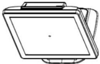 | b.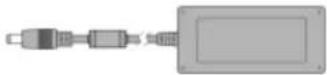 |
c.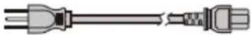 | d. |
e. | f.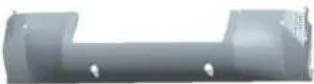 |
1-2. Optional Accessories
| a. |  | b. | 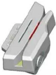 |
| c. |  |
a. System (with stand)
b. Power Adapter
c. Power Cord
d. Driver Bank
e. Screw x2
f. Cable Cover
a. Single MSR
b. 3 IN 1 MSR
c. Screw x2
2-1. Rear View Standard
* Please make sure 19V DC plug in the right direction before plugging in DC jack.
Item
- Mic
- Line-Out
- RJ11 (Cash Drawer)
- RJ45(LAN)
- USB 2.0 X4
6.COM1 - VGA
8.COM2
9. RJ45(COM 3 external)
10. PS2(K/B)
11. 19V DC Input
12. Parallel port (Option)
13. Power Button
14. MSR/Smart Card/ i-Button/ Fingerprint/ RFID (Option)
- VFD(Option)
- HDD/CF CARD
2-2. specification
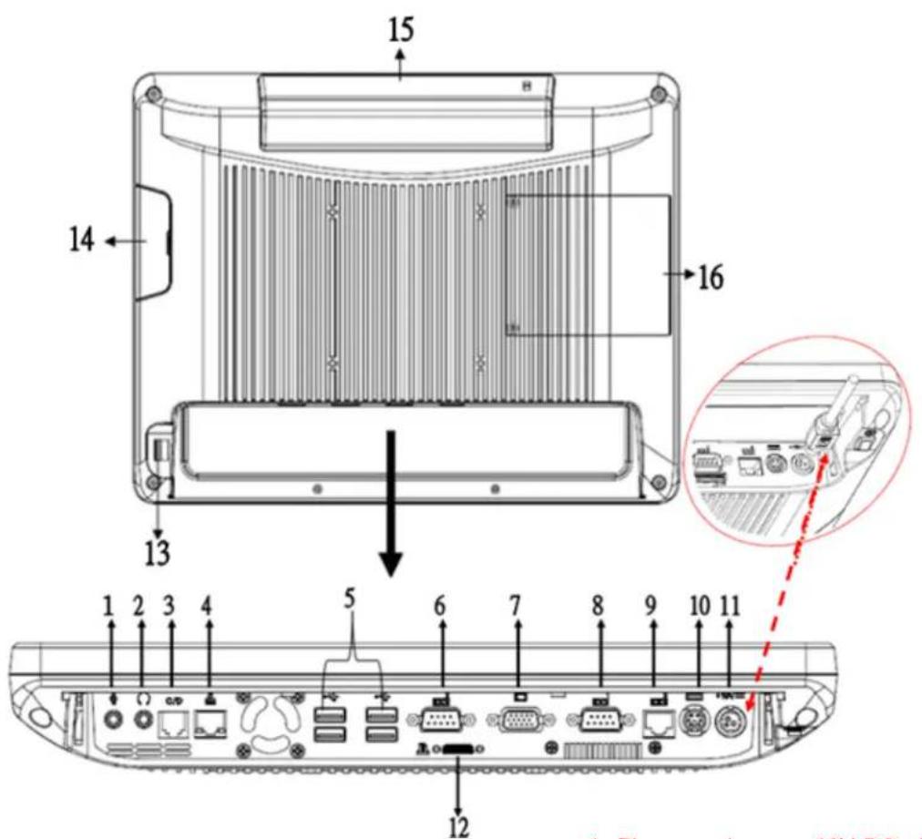
| Processor | Intel® Celeron® G540 processor (2M Cache, 2.50GHz) |
| Chipsets: North Bridge/South Bridge | H61 |
| Memory | One SO-DIMM socket supports DDR3 1333MHZ up to 4GB |
| Audio | Line-out/Mic-in |
| Network | RJ45 10/100/1000 Base-T |
| USB | 4*USB 2.0 |
| Storage | CFast type I / 2.5” SATA HDD / SSD |
| BIOS | AMI UEFI BIOS |
| Power | DC 19V 180W Adaptor |
| Thermal Solution | Heat sink + Fan X3 |
| Dimension | 368 (W) x 264.2 (H) x 285 (D) mm |
| Operating Temperature | 0°C ~ 35°C |
| Storage Temperature | -20°C ~ 60°C |
| Storage Humidity | 20% ~ 80%, non-condensing |
| Display | |
| LCD Panel Size | 15-inch TFT Active Matrix Display |
| Resolution | 1024*768 Pixels |
| Brightness | 250 cd/m2 |
| Touch Panel | 5-wire Resistive Type / optional |
| Tilt Angle | 30°~90° |
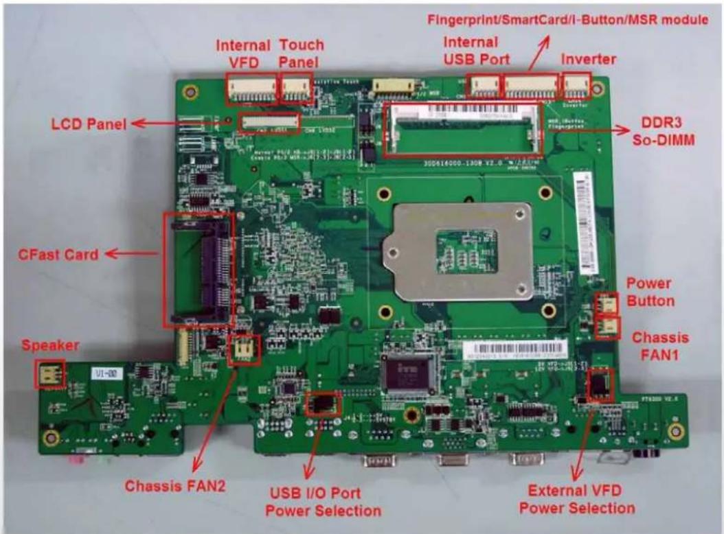
2-3. Internal Layout
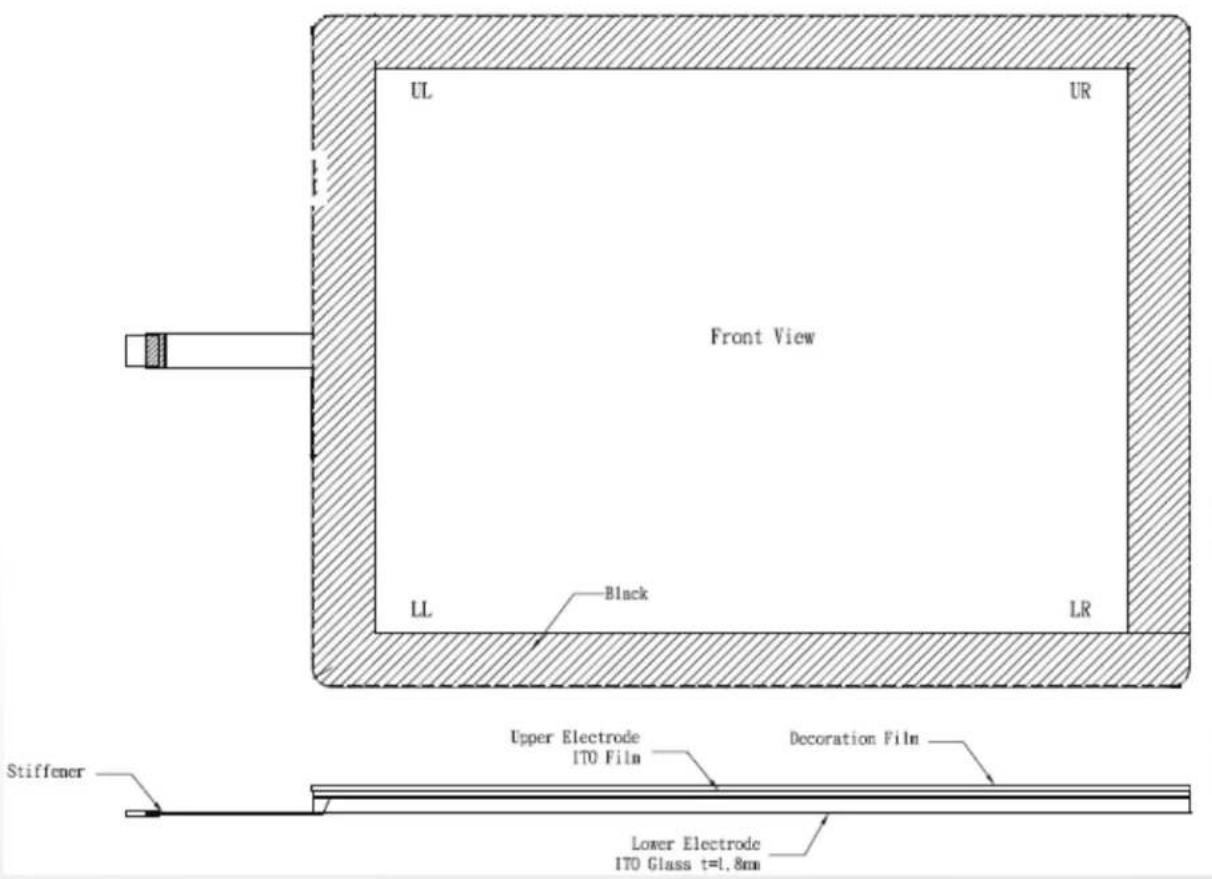
2-4. Touch Panel Life Test Condition
2-4.1 Pointing life test
Hit it thirty fi ve million times with a silicon rubber of R 0.8, Hs 60 and measure it. The measurement must satisfy the under-metioned items. Hitting force shall be 250g and hitting speed 3 times per second.
- Resistance state should the same 5.1
- Linearity should the same 5.2
- Insulation resistance should the same 5.3
2-4.2 Hand Writing test
Write one hundred thousand times of 40mm straight line to and fro (counts as twice) with and engineering plastic stylus in AA area. The measurement items must satisfy the under-mentioned items. Writing force shall be 250g and writing speed 3,000 times per hour.
- Resistance state should the same 5.1
- Linearity should the same 5.2
- Insulation resistance should the same 5.3
PIN DEFINITION
1. Parallel J7
| Pin NO. | Pin Name | Description |
| 1 | STB# | Printer Strope |
| 2 | PD0 | Parallel Port DATA0 |
| 3 | PD1 | Parallel Port DATA1 |
| 4 | PD2 | Parallel Port DATA2 |
| 5 | PD3 | Parallel Port DATA3 |
| 6 | PD4 | Parallel Port DATA4 |
| 7 | PD5 | Parallel Port DATA5 |
| 8 | PD6 | Parallel Port DATA6 |
| 9 | PD7 | Parallel Port DATA7 |
| 10 | ACK# | Printer Acknowledge |
| 11 | BUSY | Printer Busy |
| 12 | PE | Printer Paper End |
| 13 | SLCT | Printer Select |
| 14 | AFD# | Printer Auto Line Feed |
| 15 | ERR# | Printer Error |
| 16 | INIT# Printer Initialize | |
| 17 | SLIN# Printer Select Input | |
| 18 | GND Ground | |
| 19 | GND Ground | |
| 20 | GND Ground |
3. VFD Connector CN9
| Pin NO. | Pin Name | Description |
| 1 5V | +5V | |
| 2 NDSR | DSR | |
| 3 GND | Ground | |
| 4 NRTS | DTR | |
| 5 NRTS | RTS | |
| 6 | NCTS | CTS |
| 7 | NTXD | TXD |
| 8 | NRXD | RXD |
| 9 GND | Ground | |
| 10 | 12C | +12V |
4. Mic
| Pin NO. | Pin Name | Description |
| 1 GND | Ground | |
| 2 GND | Ground | |
| 3 | Mic R | Mic right |
| 4 | Mic L | Mic left |
| 5 | Detect | Delect |
2. Line-out J3
| Pin NO. | Pin Name | Description |
| 1 GND | Ground | |
| 2 GND | Ground | |
| 3 | Line OUT R | Line out |
| 4 | Line OUT L | Line out |
| 5 | Detect | Delect |
5. Speaker SP1
| Pin NO. | Pin Name | Description |
| 1 | + | Speaker + |
| 2 | - | Speaker - |
6. LVDS CN 2
| Pin NO. | Pin Name | Description |
| 1 | LCDVCC +3.3v | |
| 2 | LCDVCC +3.3v | |
| 3 | GND Ground | |
| 4 NC | NC | |
| 5 | DATA 0- | LVDS Output DATA0- |
| 6 | DATA 0+ | LVDS Output DATA0+ |
| 7 | GND Ground | |
| 8 | DATA 1- | LVDS Output DATA1- |
| 9 | DATA 1+ | LVDS Output DATA1+ |
| 10 | GND Ground | |
| 11 | DATA 2- | LVDS Output DATA2- |
| 12 | DATA 2+ | LVDS Output DATA2+ |
| 13 | GND Ground | |
| 14 | CLK- | LVDS CLK- |
| 15 | CLK+ | LVDS CLK+ |
| 16 | GND Ground | |
| 17 NC | NC | |
| 18 NC | NC | |
| 19 | GND Ground | |
| 20 NC | NC | |
7. Inverter CN14
| Pin NO. | Pin Name | Description |
| 1 VCO | +12V | |
| 2 GND | Ground | |
| 3 NC | NC | |
| 4 | BKL_CTL | Back Light Brightness |
| 5 | BKL_EN | Back Light Enable |
8. Extra USB CN13
| Pin NO. | Pin Name | Description |
| 1 VCC | +5V | |
| 2 - DATA D- | ||
| 3 + DATA D+ | ||
| 4 GND | Ground | |
| 5 GND | Ground | |
1. COM1' COM2' COM3 port
| Pin Signal Function | ||
| 1 CD Carrier Detect (IN) | ||
| 2 RD Receive Data (IN) | ||
| 3 TD Transmit Data(OUT) | ||
| 4 DTR Data Terminal Ready(OUT) | ||
| 5 GND Ground | ||
| 6 | DSR Data Set Ready (In) | |
| 7 RTS | Request To Send (OUT) | |
| 8 CTS | Clear To Send (IN) | |
| 9 | Ring/5V/12V | Setting by BIOS |
COM3 port. Warning!! COM3 (RJ45 Connector) for external VFD use only. Never use on network device. If you are using on the network device will cause the device damaged.
COM 3 port will be inactive if POS has internal VFD. (Alternative of COM 3 or internal VFD)
2. VGA port
| Pin | I/O | Function |
| 1 | Out | Red Video |
| 2 | Out | Green Video |
| 3 | Out | Blue Video |
| 4 | In | Monitor ID 2 |
| 5 | - | TTL Ground(Monitor Self Test) |
| 6 | - Red Analogue Ground | |
| 7 | - | Green Analogue Ground |
| 8 | - | Blue Analogue Ground |
| 9 | - | Key (Plugged Hole) |
| 10 - | Sync Ground | |
| 11 | In | Monitor ID 0 |
| 12 | In | Monitor ID 1 |
| 13 Out | Horizontal Sync | |
| 14 Out | Vertical Sync | |
| 15 | In | Monitor ID 3 |
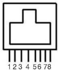
natural_image
Pure electrical connector pinout diagram without any text or symbolsPin 1: +5V / +12V
Pin 2: DSR#
Pin 3: GND
Pin 4: DTR#
Pin 5: RTS#
Pin 6: CTS#
Pin 7: TxD
Pin 8: RxD
- USB port
| Pin | Signal Name | Wire Colour | Comment |
| 1 | Vcc | Red Cable Power | |
| 2 | - Data | White | Data Transfer |
| 3 | + Data | Green | Data Transfer |
| 4 | Ground | Black | Cable Ground |
| Shell | Shield - | Drain Wire | |
- RJ11 port (for Cash drawer)
| Pin | Signal Name Direction | |
| 1 | Frame GND | - |
| 2 | Drawer Kick-out drive signal 1 | Output |
| 3 | N/C | - |
| 4 | +12V | - |
| 5 | N/C | - |
| 6 | Signal GND | - |
- PS/2 K/B port
| Pin | Signal Name |
| 1 | Data from Device |
| 2 | Not Connected |
| 3 | Ground |
| 4 | +5V DC |
| 5 | Clock |
| 6 | Not Connected |
Example DOS COMMAND for Cash Drawer:
-
Create the file: TEST.TXT
-
Input below contents in TEST.TXT CONTEXT-"000.0" MODE COM5:300
-
Run COMMAND under DOS mode COPY TEST.TXT COM5
-
DC Jack
- LAN port
| Pin Wire Colour Description | ||
| 1 White/Orange Transmit | ||
| 2 Orange Transmit | ||
| 3 White/Green Receive | ||
| 4 Blue Not Used | ||
| 5 White/Blue Not Used | ||
| 6 | Green | Receive |
| 7 | White/Brown | Not Used |
| 8 | Brown | Not Used |
| Pin | Signal Name |
| 1 | DC IN 19V |
| 2 | Ground |
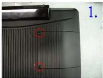
3-1. HDD
natural_image
Close-up of a black plastic component with two red circular annotations highlighting features (no readable text or symbols)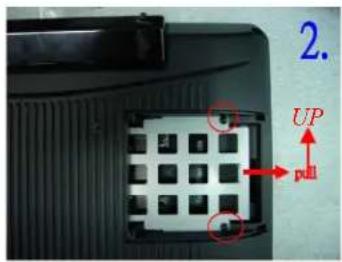
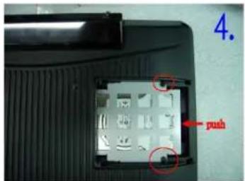
natural_image
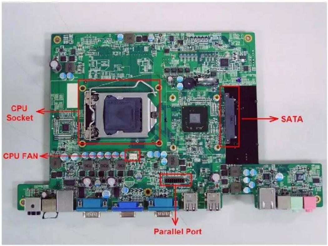
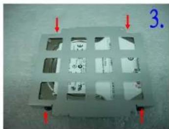
Metallic tray with multiple compartments and red arrows pointing to features, labeled '3.' (no text or symbols on the tray itself)- Unfasten the HDD cover screw*2
- Pull out the HDD bracket
- Fasten the screw*4
- Place the HDD bracket back to the module
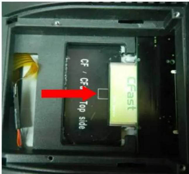
3-2. CF-Card
- Please notice the notched CF Card. This side up.
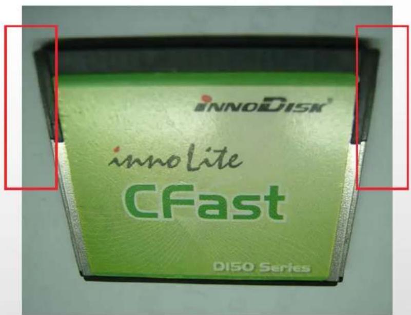
- Before Installing CF Card.
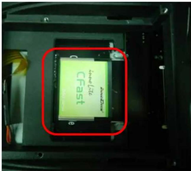
- After Installing CF Card.
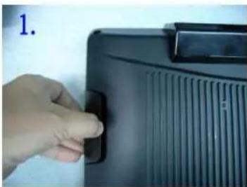
3-3. MSR
natural_image
Hand pressing a button on a black electronic device (no visible text or symbols)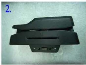
natural_image
Black plastic electronic device with ventilation slots and a 4-pin connector (no visible text or symbols)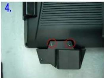
natural_image
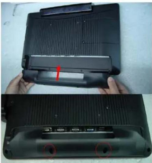
Close-up of a black plastic component with a red circular annotation and two small green dots, no visible text or symbols.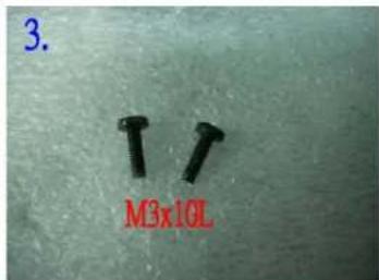
- Open the MSR cover
- Single MSR or 4in1MSR
- Screw*2 M3x10L
- Fasten the screw
3-4. Cable Cover
natural_image
Two views of a black plastic device showing internal components and a red arrow indicating a specific part (no text or symbols visible)Assemble the cable cover from bottom and make sure the two latches are on the right position. Then fasten 2 screws (M3*5L).
3-5. 8"/15" 2nd Display
natural_image
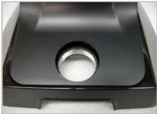
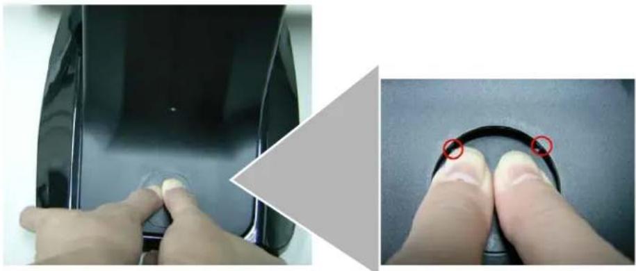
Close-up of a black plastic mechanical component with a threaded circular hole (no text or symbols visible)(1) Remove the plastic pole cover from the stand.
natural_image
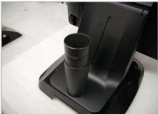
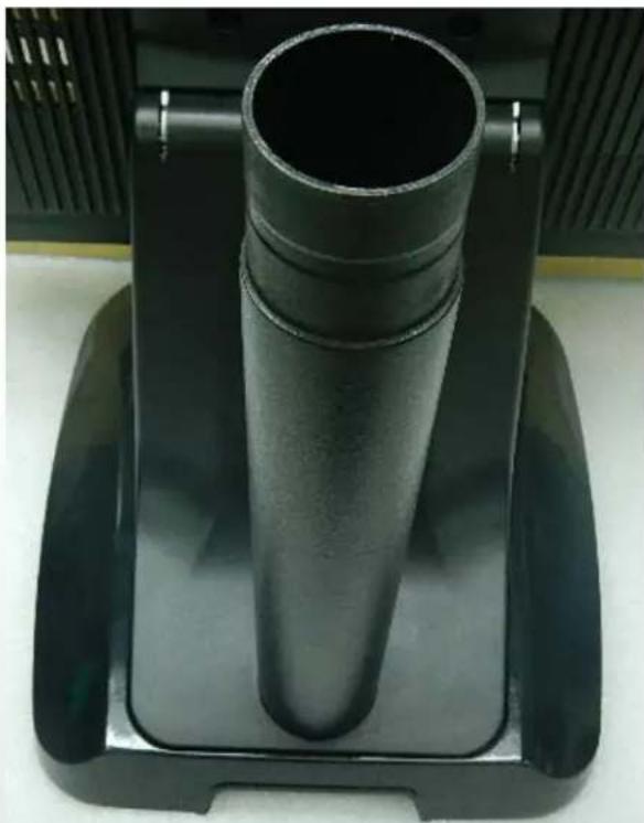
Close-up of a black plastic spray machine with three cylindrical cups on a base (no visible text or symbols)(2) Install the pole into the socket in clockwise direction.
natural_image
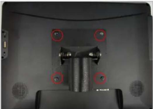
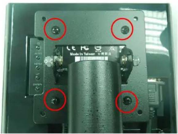
Close-up of a mechanical component with four red-circled holes and mounting holes (no visible text or symbols)(3) Fasten the four screws (M4*8L) to joint the VESA bracket and the rear cover.
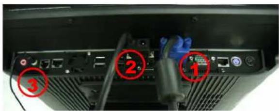
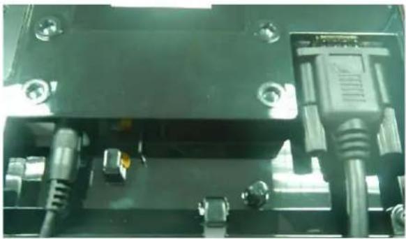
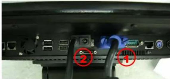
(4) Connect the COM port, DC cable as shown in figure (1). (Please refer to page 61 to set the COM port pin9 with 12V DC output.)
(5) Connect the VGA cable as shown in figure (2).
(6) Connect the audio cable as shown in figure(3).
(7) Assemble the cable cover from bottom and make sure the two latches are on the right position, and fasten the two screws (M3*5L).
(8) Route the cables through the opening of stand front cover and cable clip at the bottom and route the cables into the tube of pole.
natural_image
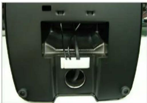
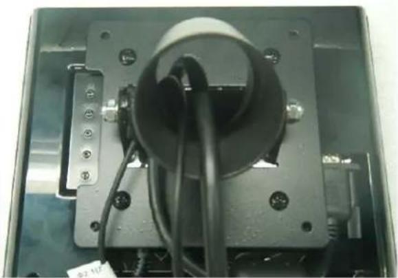
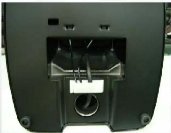
Interior view of a black electronic device with visible internal components and mounting holes (no text or symbols)(9) Reeve the cables out of the tube.
natural_image
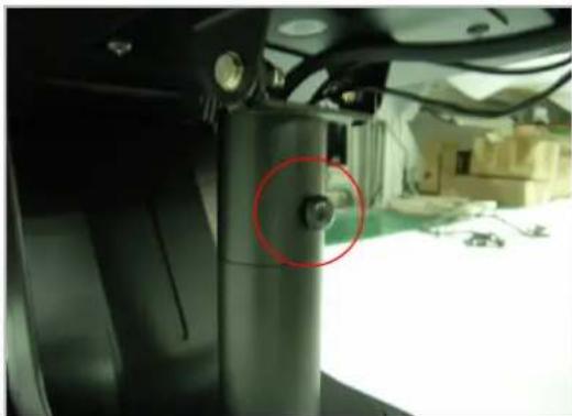
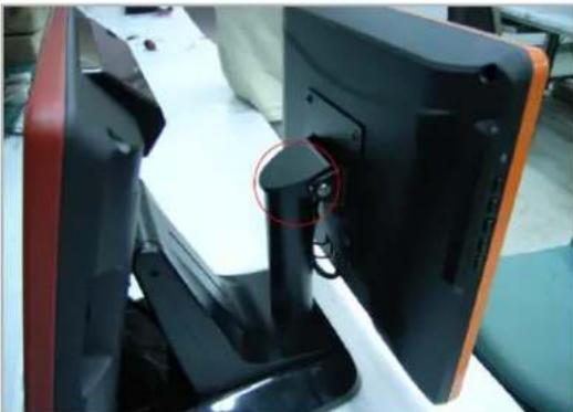
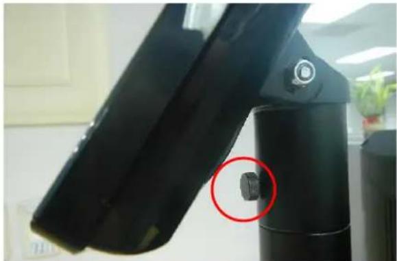
Close-up of a mechanical component with a red circle highlighting a bolt, no visible text or symbols(10) Mount the VESA bracket on the pole and route cables out of the tube of VESA bracket. Fasten the thumb screw to fix the VESA bracket.
natural_image
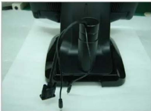
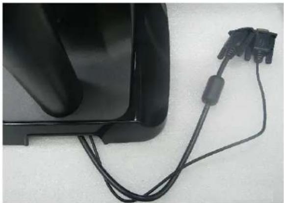
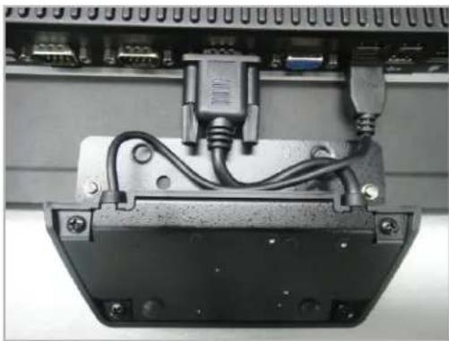
Close-up of a black electronic device with attached cable and connector, placed on a white surface (no visible text or symbols)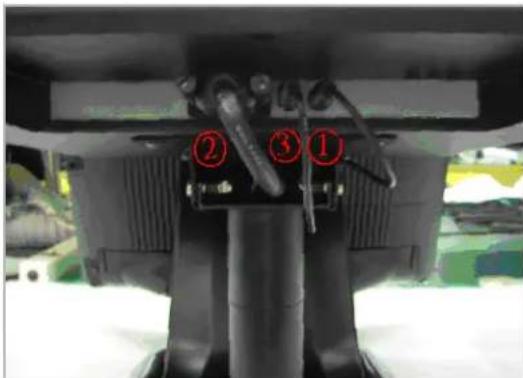
(11) Connect the DC power cable as shown in figure (1).
(12) Connect the VGA cable as shown in figure (2).
(13) Connect the Audio cable as shown in figure (3).
natural_image
Close-up of a black electronic device with a red circular annotation highlighting a key component (no visible text or symbols)(14) Put the cable cover on the hinge of VESA bracket.
3-6. 8" 2nd Display
- Remove the plastic pole cover from the stand.
natural_image
Close-up of hands adjusting a black car door panel, showing the edge and finger positioning (no text or symbols visible)- Install the pole into the socket in clockwise direction.
natural_image
Close-up of a black cylindrical mechanical component mounted on a black base, with no visible text or symbols.- Connect VGA cable and DC power cable
natural_image
Close-up of a mechanical or electronic component with metallic pins and connectors (no visible text or symbols)- Fasten the four screws (M4*8L) to joint the VESA bracket and the rear cover.
- Reeve the cables out of the tube.
natural_image
Close-up of a mechanical component with wires and connectors, no visible text or symbols- Mount the VESA bracket on the pole and route cables out of the tube of VESA bracket. Fasten the thumb screw to fix the VESA bracket.
natural_image
Close-up of a black mechanical device with a red circular annotation highlighting a small component (no visible text or symbols)- Reeve the cables out from the bottom of pole.
natural_image
Close-up of a black electronic device with two connected cables (no visible text or symbols)- Route the cables through the opening of stand front cover and cable clip at the bottom and route the cables into the tube of pole.
natural_image
Back view of a black electronic device with internal components and mounting holes (no visible text or symbols)-
Connect the DC power cable as shown in figure (1).
-
Connect the VGA cable as shown in figure (2).
To setup COM port PIN9 with 12V DC output from BIOS setup, please refer to page 89, Advanced Chipset Features / COM port PIN9 setting.
- Put the cable cover on the hinge of VESA bracket.
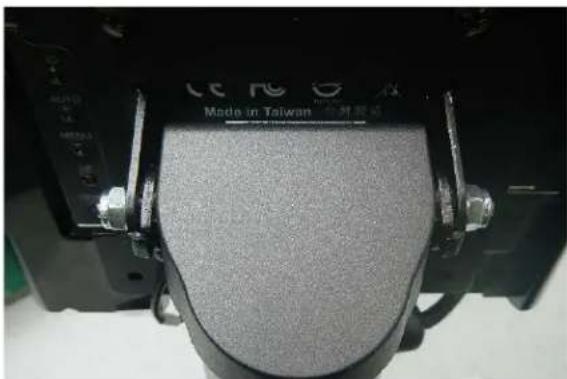
natural_image
Close-up of a mechanical component with metallic fittings and a textured surface, labeled 'Made in Taiwan' (no readable text beyond label)3-7. 1D / 2D / iButton with RFID Module
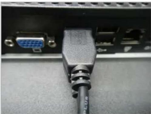
natural_image
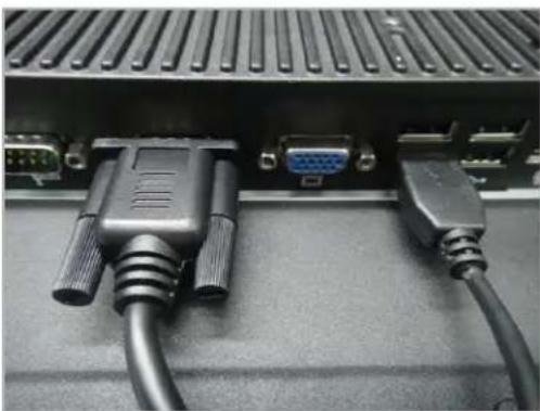
Close-up of a black VGA connector with a blue GND and a USB cable inserted, mounted on a computer drive (no visible text or symbols)(1) Cable installation. For iButton with RFID module; For 2D barcode scanner with RFID module: Connect the cable as shown.
natural_image
Close-up of an electronic device housing with visible wiring and connectors (no text or symbols)(3) Fix the screws as shown.
natural_image
Close-up of a black VGA connector with two cables, showing ports and connectors (no text or symbols visible)(2) For 1D barcode scanner with RFID module: Connect the cable as shown.
* Before COM port cable connection, please setup COM port PIN9 with 5V DC output from BIOS setup.
Please refer to page 83, Advanced Chipset Features / COM port PIN9 setting.
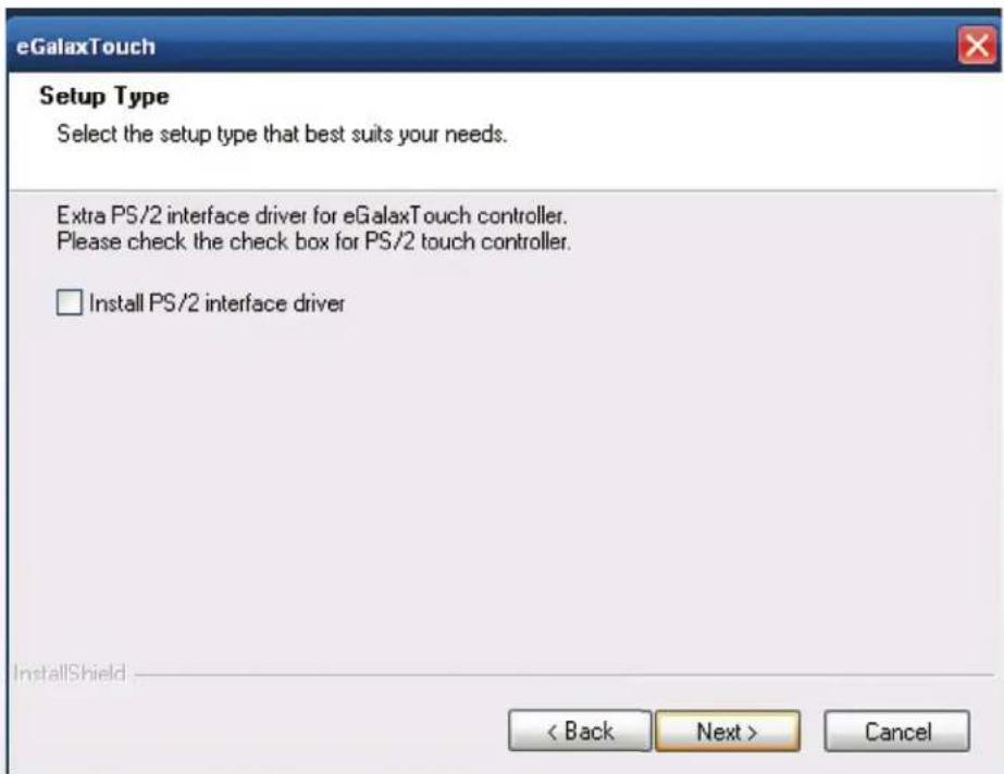
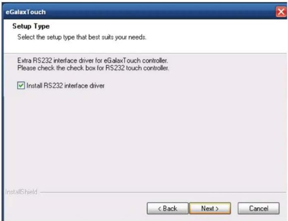
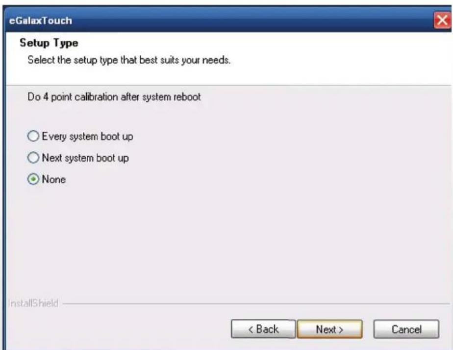
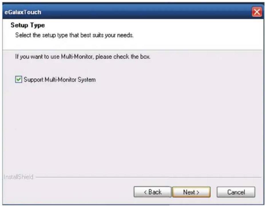
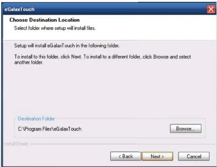
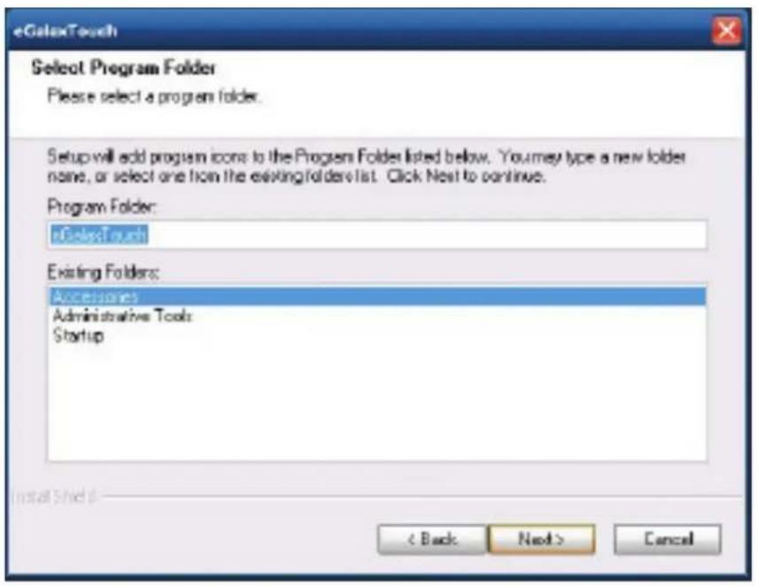
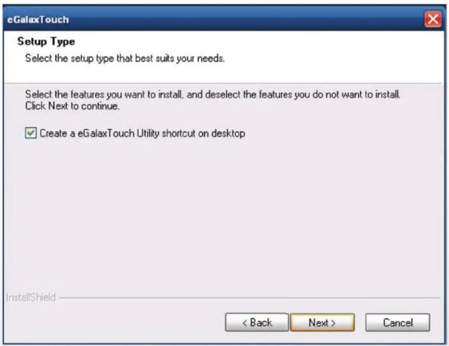
4-1. Resistive Type Touch Panel
1. Click "Next"
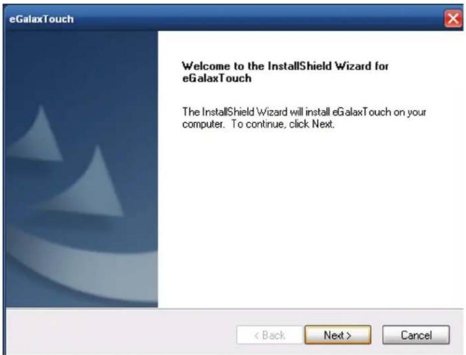
2. Click "Next"
3. Click "Next"
4. Select "None", Click "Next".
- Click "OK"

- Select "Support Multi-Monitor System", Click "Next".
- Click "Next".
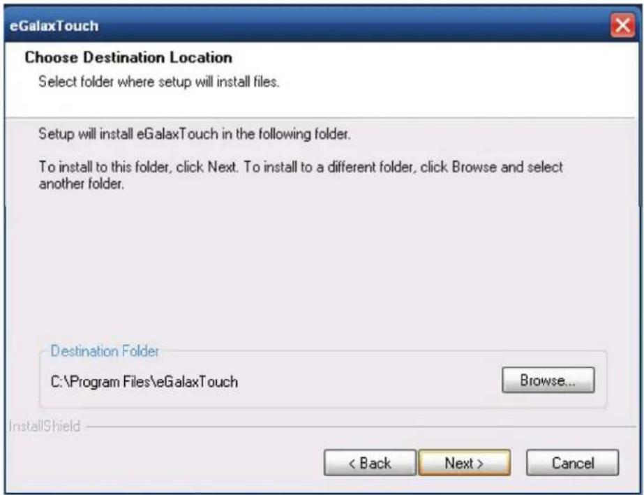
- Click "Next".
9 Click "Next"
- Select "Create a eGalaxTouch Utility shortcut on desktop", Click "Next".
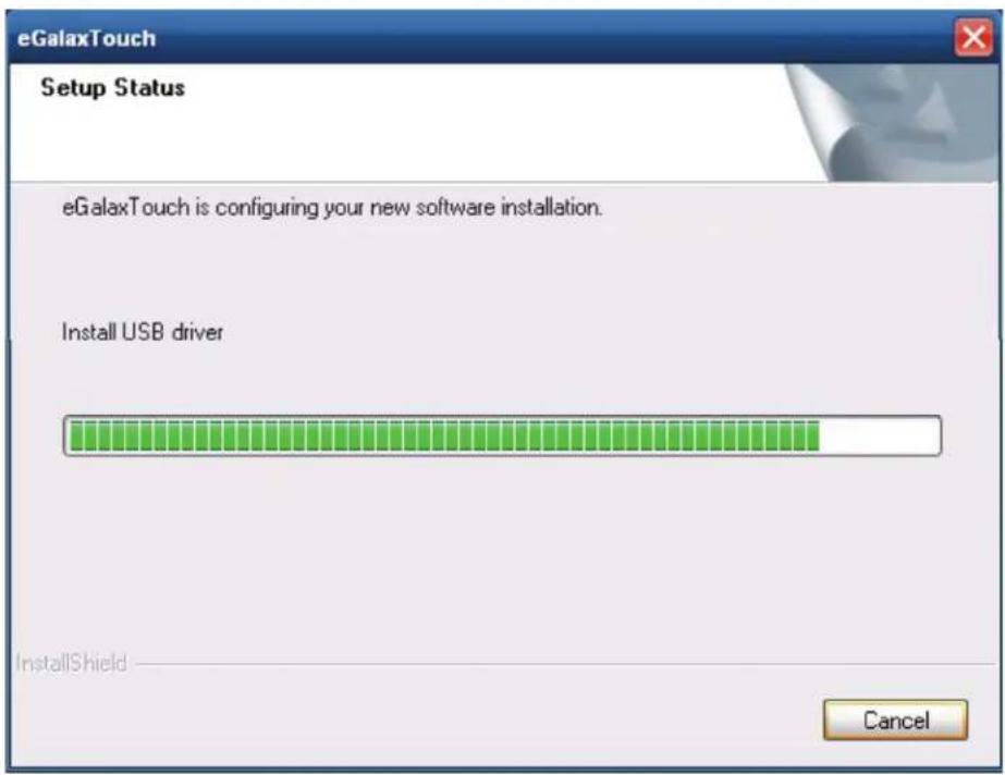
- Would you do 4 point calibration now? Click "Yes".

- Do 4 points alignment to match display


- Calibration utility

4-2. MagStripe Card Reader Configuration Utility
The MagStripe Card Reader Configuration Utility is used to set up the output format of HID MSR.
Installation
Below steps guide you how to install the Utility program.
1 Insert the setup CD
2 Run the HID_MSR_PSW00003_V2_0_0.exe setup file that is located in the Software folder of CD.
3 Follow the wizard to complete the installation.
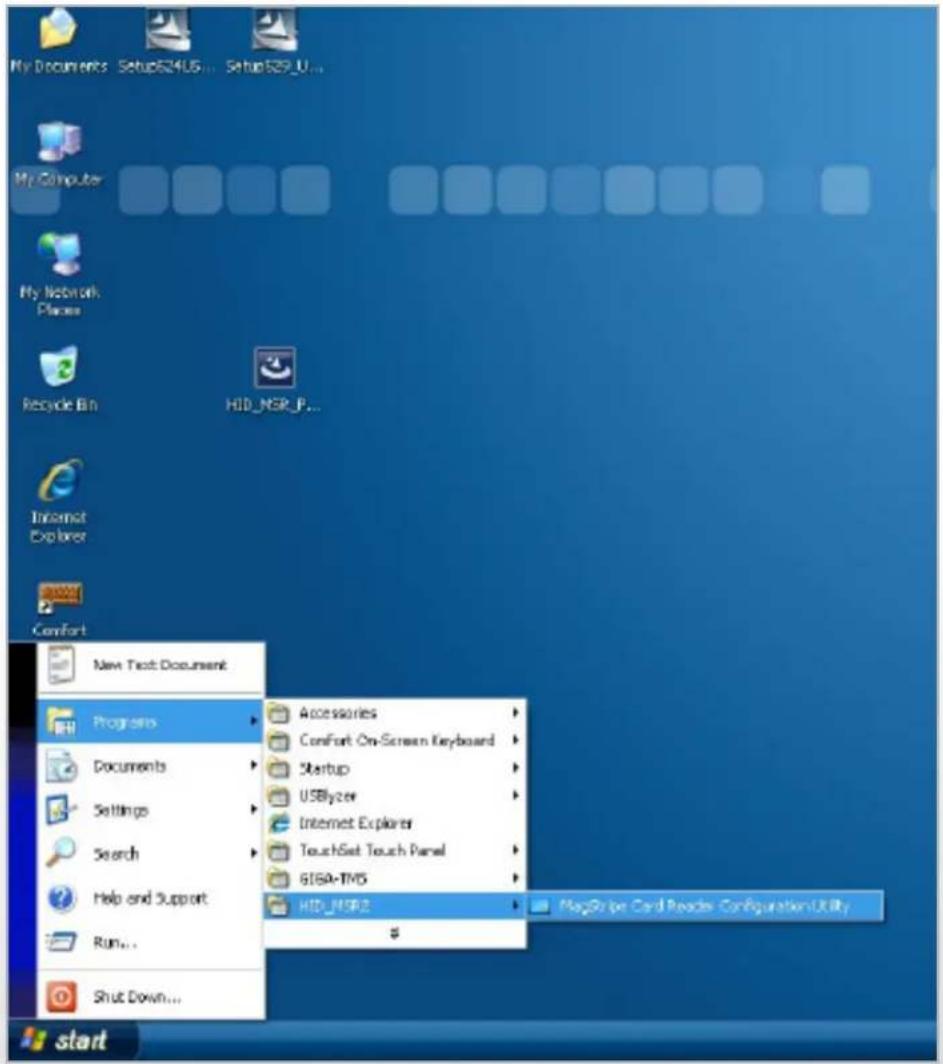
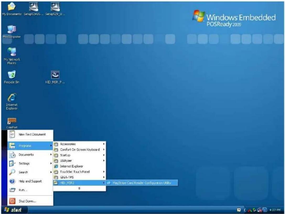
Launching Program
Below steps guide you how to load the Utility program.
1 From Start/Programs, click HID_MSR2 folder
2 Click MagStripe Card Reader Configuration Utility to launch the program.
1 The utility program will detect the connected reader. If detected, all the input text boxes will be enabled.
2 If the reader has not been connected to PC yet, please connect the reader and then click Refresh to get connected.
Configuration
Below is the main window of Utility program.
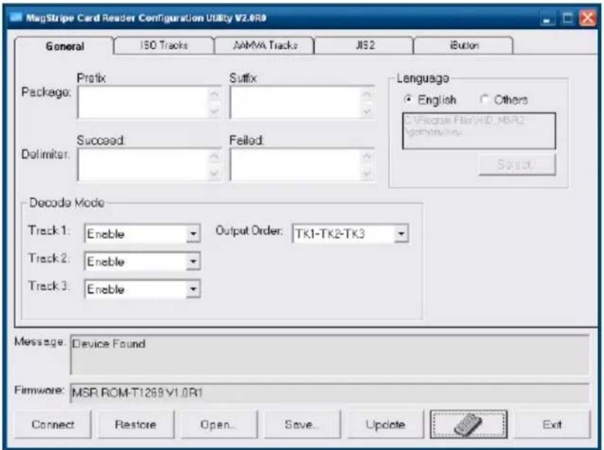
for the settings, there are:
1 Language: The language defines the code positions of the keyboard. Each language should use its own settings. Wrong language selected will cause the wrong character displayed.
2 Prefix/Suffix: Defines the data string which you would like to append in front or end of the MSR data string.
3 Error Message: Indicates which track number cause the error.
4 Delimiter: Indicates the swipe result.
5 ISO: Define start and end sentinel character.
6 Decode Mode: Determines the way of outputting the three tracks data.
Shown below is the data structure of the output string for MSR.
PP PR1 SS1 TK1 ES1 SU1 PR2 SS2 TK2 ES2 SU2 PR3 SS3 TK3 ES3 SU3 SU DM
1 PP: Prefix for package.
2 PR1: Prefix for track 1.
3 SS1: Start sentinel for track 1.
4 TK1: Data for track 1, if error happens, using Error Message instead.
5 ES1: End sentinel for track 1.
6 SU1: Suffix for track 1.
7 PR2: Prefix for track 2.
8 SS2: Start sentinel for track 2.
9 TK2: Data for track 2, if error happens, using Error Message instead.
10 ES2: End sentinel for track 2.
1 SU2: Suffix for track 2.
2 PR3: Prefix for track 3.
3 SS3: Start sentinel for track 3.
4 TK3: Data for track 3, if error happens, using Error Message instead..
5 ES3: End sentinel for track 3.
6 SU3: Suffix for track 3.
7 SU: Suffix for package.
8 DM: Delimiter for the swipe result.
Prefix/Suffix
In default, the prefix and suffix settings are all keep blank. There are 4 kinds of prefix and suffix to be defined, which are:
1 Package: For the prefix string, it is appended in the front of the whole MSR data. For the suffix, it is appended in the end of the whole MSR data. In most case, the suffix for package is always to be the "Enter" or "Tab" character. The max data length of the prefix and suffix for the package can be up to 127.
2 TK1: For the prefix string, it is appended in the front of the start sentinel of track 2. For the suffix, it is appended in the end of the end sentinel of track 2. The max data length of the prefix and suffix for the TK1 can be up to 127.
3 TK2: For the prefix string, it is appended in the front of the start sentinel of track 2. For the suffix, it is appended in the end of the end sentinel of track 2. The max data length of the prefix and suffix for the TK1 can be up to 127.
4 TK3: For the prefix string, it is appended in the front of the start sentinel of track 3. For the suffix, it is appended in the end of the end sentinel of track 3. The max data length of the prefix and suffix for the TK1 can be up to 127.
ISO
This group defines the start and end sentinel for each track. The sentinel is always used to extract the track data from the whole MSR data string. The data length for each sentinel is fixed to one character. Because there is ISO standard that defining the start and end sentinel for the three tracks. For the compatible reason, please do not modify the default value if possible.
Decode Mode
For this group, it contains two kinds of settings, which are:
1 Track Data Filtering: Determine which track to be, not to be output or needed to be output.
2 Switch Output Order: Change the output order of track 1 \~ 3.
Track Data Filtering
Shown below is the filter setting for track 1. This provides a fool-proofing method in case of receiving unwanted or uncompleted track data.
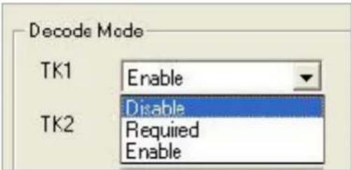
These three filter settings are:
1 Enable: If selected, the data of specified track will be packaged in the MSR data string. If the specified track data is not decoded, it will leave blank in the MSR data string.
2 Required: If selected, which means the output MSR data string must contain the specified track data. If the specified track data is not decoded, even MSR data string contains other track data, it will still not to be output.
3 Disable: If selected, the data of specified track will not be packaged in the MSR data string. No matter it is decoded or not.
Switch Output Order
Show below is the selection of the three track data output order (sequence). The default order is Track 1-Track 2-Track 3.
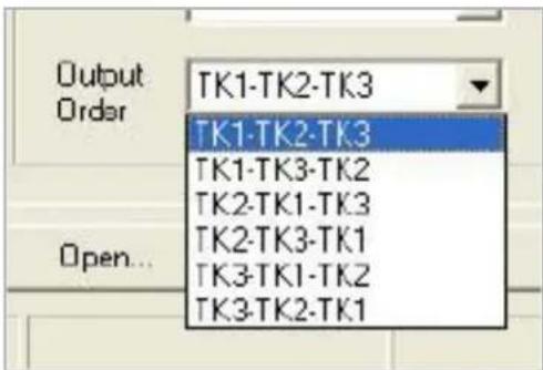
There 6 orders allow to be selected. Please select one to fit your application needs.
Update Settings
Once complete the settings, click Update to update the settings to connected HID MSR reader.
Save Settings To save the settings to a file, click Save; specify the file name and location to be saved. Open Settings To load pre-saved settings, click Open, specify the settings file, and then click OK to load into program. Restore MSR Reader Settings To load restore settings of connected MSR reader, click Restore ES2: End sentinel for track.
4-3. Fingerprint Reader
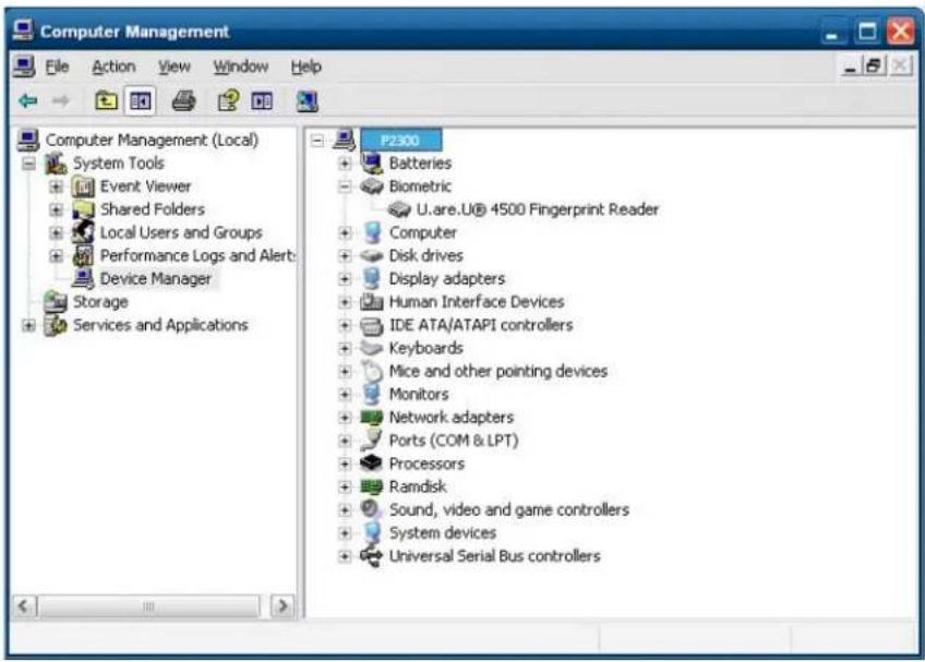
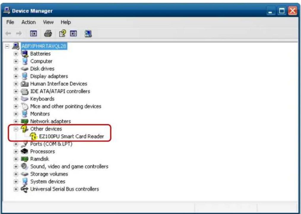
Step 1 Check Fingerprint reader be detected by "Device manager"

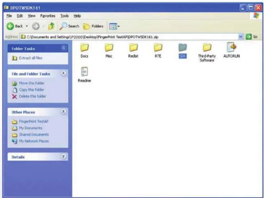
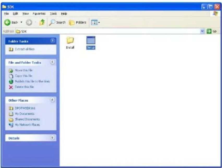
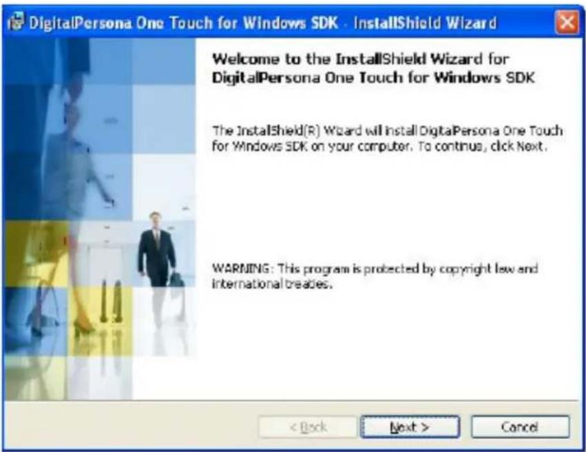
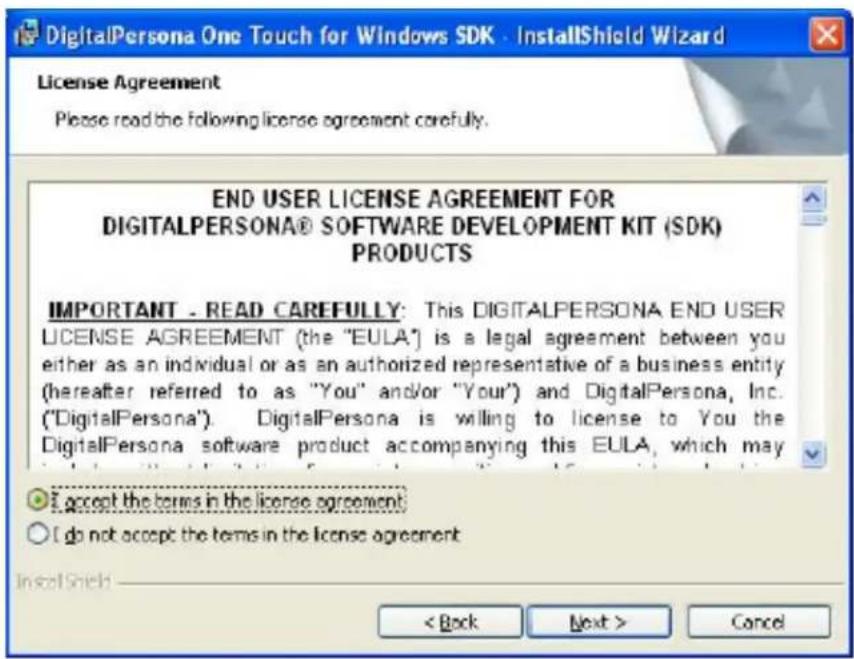
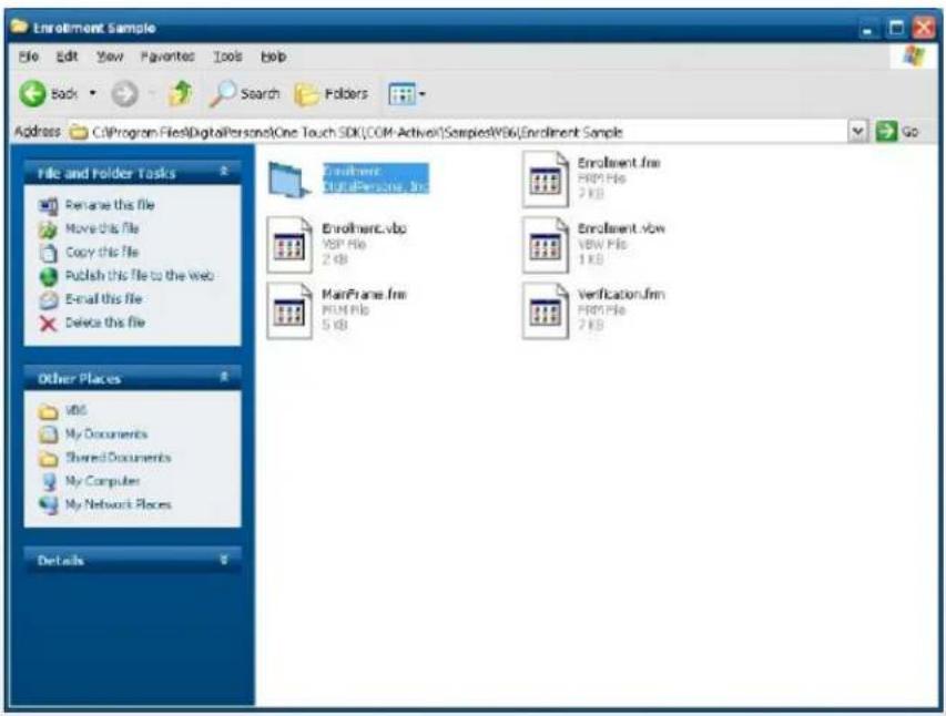
Step 2 Unzip and run Setup.exe from the following folder.
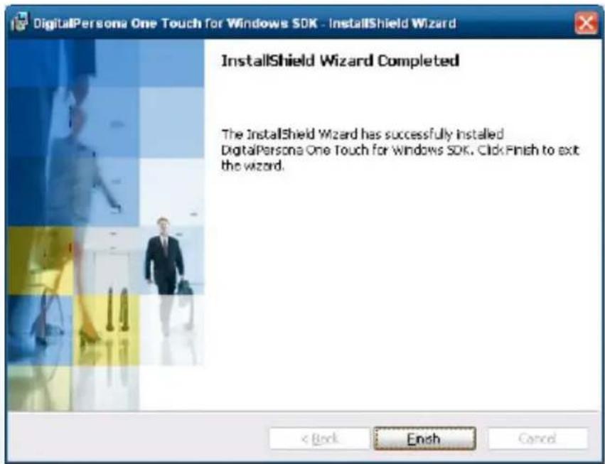
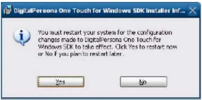
Step 3 Restart system
Step 4 Check Fingerprint reader in device without any extraordinary.
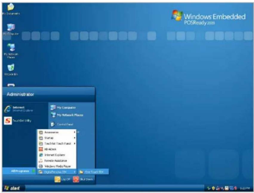
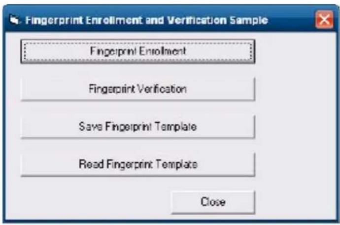
Step 5 Launch Fingerprint reader from start menu
Step 6 Enroll the fingerprint by the "enrollment"
Step 7 Select "Fingerprint Enrollment"
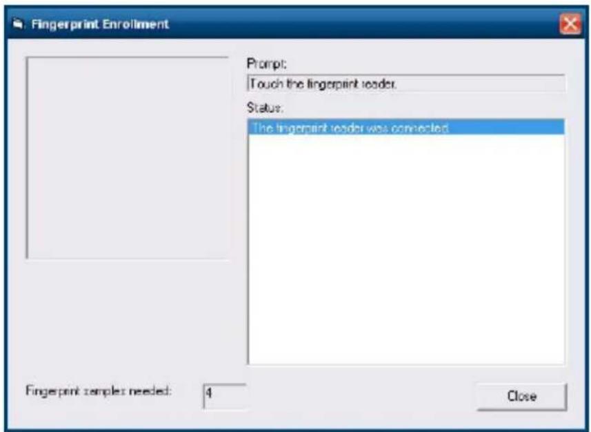
Step 8 Put your finger on fingerprint reader and follow the direction to enroller your fingerprint, it need scan your fingerprint 4 times
Step 9 after enroller finish it will popup a dialog box
![Windows Embedded POSReady 2009 Fingerprint Enrollment Format Click Close, and then click Fingerprint Verification. Status: The fingerprint sample was captured. The fingerprint tissue was created. The fingerprint was removed from the fingerprint reader. The fingerprint reader was successfully identified. Enrolment Simple is good. Created are fingerprint reader. made is good. Created Created The fingerprint was removed from the fingerprint reader. The fingerprint reader was successfully identified. The quality of the fingerprint sample is good. The fingerprint sample was successfully identified. The fingerprint reader was not selected. Fingerprint samples needed Close Start PP-12 - [ ] [ ] [ ] [ ] [ ] [ ] [ ] [ ] [ ] [ ] [ ] [ ] [ ] [ ] [ ] [ ] [ ] [ ] [ ] [ ] [ ] [ ] [ ] [ ] [ ] [ ] [ ] [ ] [ ] [ ] [ ] [ ] [ ] [ ] [ ] [ ] [ ] [ ] [ ] [ ] [ ] [ ] [ ] [ ] [ ] [ ] [ ] [ ] [ ] [ ] [ ] PP-12 - [ ] [ ] [ ] [ ] [ ] [ ] [ ] [ ] [ ] [ ] [ ] [ ] [ ] [ ] [ ] [ ] [ ] [ ] [ ] [ ] [ ] [ ] [ ] [ ] [ ] [ ] [ ] [ ] [ ] [ ] [ ] [ ] [ ] [ ] [ ] [ ] [ ] [ ] [ ] [ ] [ ] [ ][ ][ ][ ][ ][ ][ ][ ][ ][ ][ ][ ][ ][ ][ ][ ][ ][ ][ ][ ][ ][ ][ ][ ][ ][ ][ ][ ][ ][ ][ ][ ][ ][ ][ ][ ][ ][ ][ ][ ][ ][ ][ ][ ][ ][ ][ ][ ][ ][ ][ ][ ][ ][ ][ ][ ][ ][ ][ ][ ][ ][ ][ ][ ][ ][ ][ ][ ][ ][ ][ ][ ][ ][ ][ ][ ][ ][ ][ ][ ][ ][ ][ ][ ][ ][ ][ ][ ][ ][ ][ ][ ][ ][ ][ ][ ][ ][ ][ ][ ][ ][ ] PP-12 - [ ][ ],[ ],[ ],[ ],[ ],[ ],[ ],[ ],[ ],[ ],[ ],[ ],[ ],[ ],[ ],[ ],[ ],[ ],[ ],[ ],[ ],[ ],[ ],[ ],[ ],[ ],[ ],[ ],[ ],[ ],[ ],[ ],[ ],[ ],[ ],[ ],[ ],[ ],[ ],[ ],[ ],[ ],[ ],[ ],[ ],[ ],[ ],[ ],[ ],[ ],[ ] PP-12 - [ ],[ ],[ ],[ ],[ ],[ ],[ ],[ ],[ ],[ ],[ ],[ ],[ ],[ ],[ ],[ ],[ ],[ ],[ ],[ ],[ ],[ ],[ ],[ ],[ ],[ ],[ ],[ ],[ ],[ ],[ ],[ ],[ ],[ ],[ ],[ ],[ ],[ ],[ ],[ ],[ ],[ ],[ ],[ ],[ ],[ ],[ ],[ ],[ ],[ ],( )](/content/2026/05/1058453/images/b78370adc85cc3a8d7bac00b6cb50af949aee8fa0633736c0db7079afde8c9f6.jpg)
4-4. rfiD
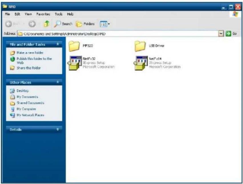
- Install (Operating System: Microsoft Windows POSReady 2009)
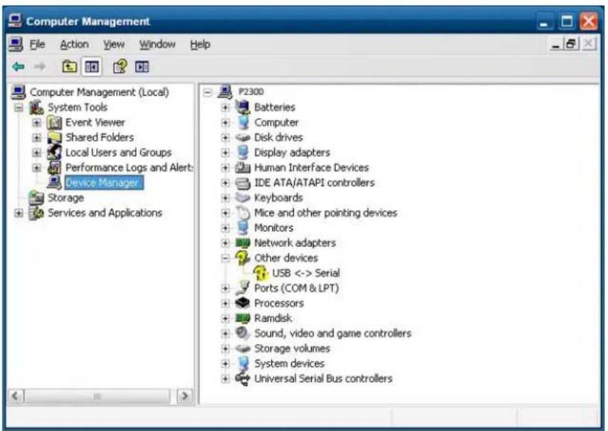
1.2.2 1.1 Check the Device Manager to verify the status of RFID reader.
Computer Management -> Device Manager -> Other devices
(The device will show a question mark if the installation is not done properly.)
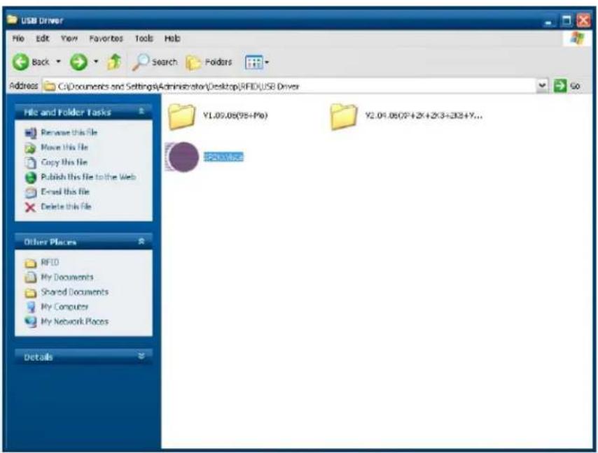
1.2 Install RFID driver file name: XP2KxVista.exe
2-1 Path:\USB Driver\ XP2KxVista.exe
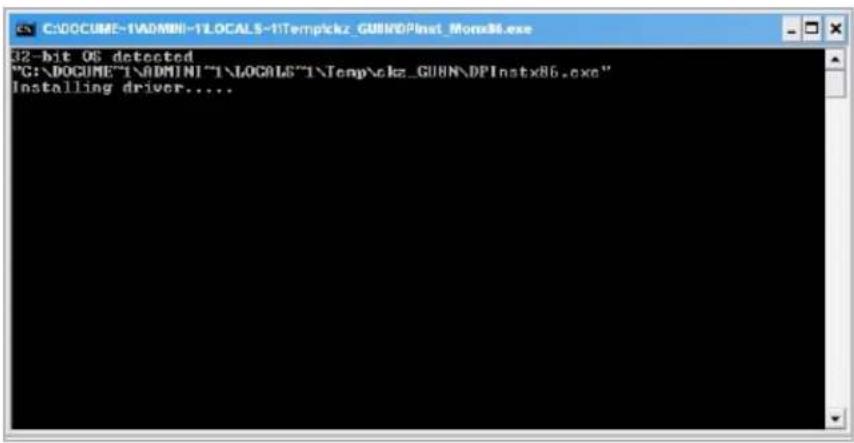
1.2.1 After clicking Next, A pop up console window appears as below.
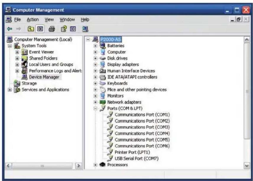
1.2.2 Check the Device Manager to verify the status of RFID reader. Computer Management -> Device Manager -> Ports (COM & LPT)
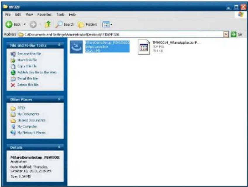
1.3 install RFID utility
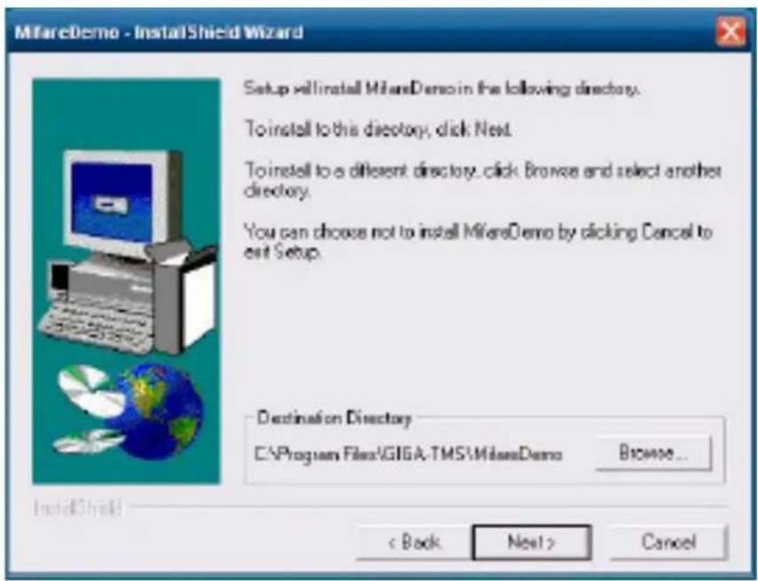
MifareDemoSetup_PSW00020.exe
3-1 Path:\MF320\MifareDemoSetup_PSW00020.exe
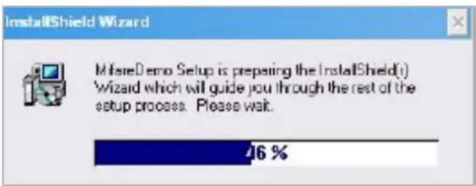
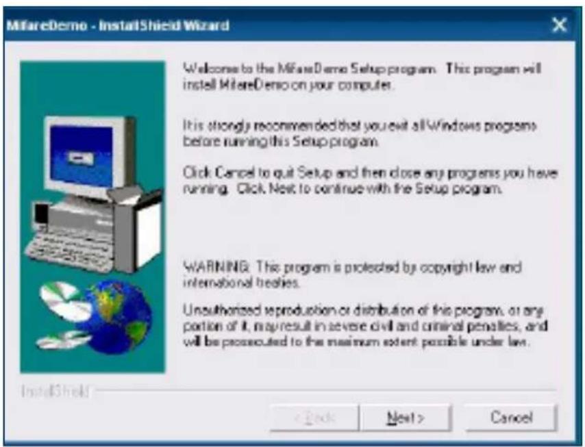
1.3.1 InstallaShield Wizard will be activated.
1.3.2 Click "Next"
1.3.3 Click "Next"
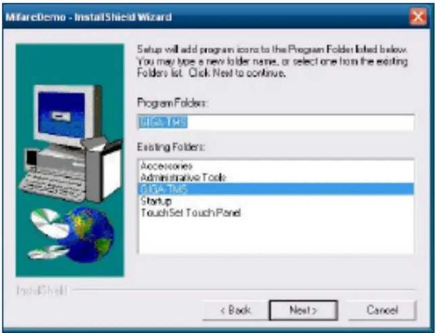
1.3.4 Click "Giga-TMS" & "Next"
1.3.5 Click "Next"
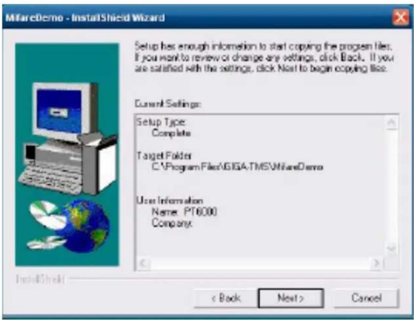
1.3.6 Click "Next"
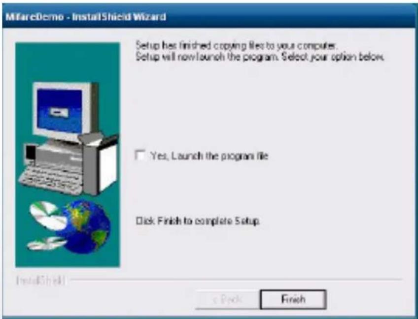
2 Run RFID demo program. Start -> All Programs -> GIGA-TMS -> Mifare Demo
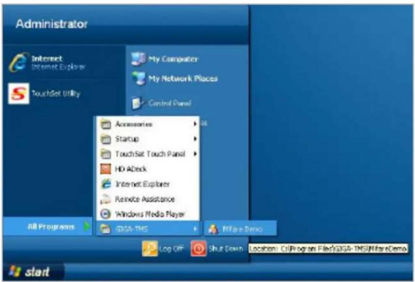
2-1 Run "Auto Scan" Demo AP will detect the RFID reader automatically. Or select the RFID COM port
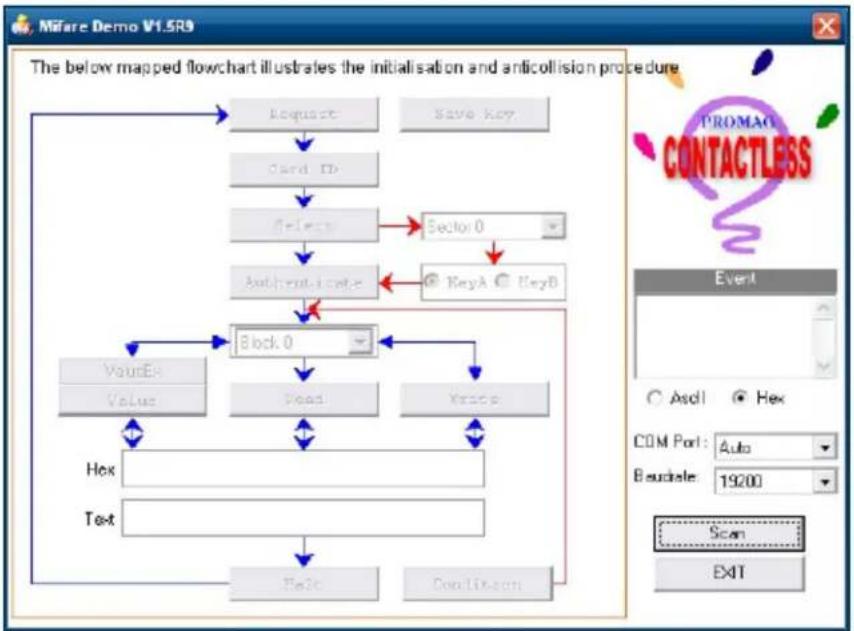
flowchart
graph TD
    A["Request"] --> B["Card ID"]
    B --> C["Select"]
    C --> D["Authentication"]
    D --> E["Block 0"]
    E --> F["Value"]
    E --> G["Read"]
    E --> H["Write"]
    F --> I["Hex"]
    G --> J["Test"]
    H --> K["Find"]
    K --> L["SendTo.com"]
    C --> M["KeyA"]
    M --> N["KeyB"]
    style A fill:#f9f,stroke:#333
    style B fill:#ccf,stroke:#333
    style C fill:#cfc,stroke:#333
    style D fill:#fcc,stroke:#333
    style E fill:#cff,stroke:#333
    style F fill:#ffc,stroke:#333
    style G fill:#ffc,stroke:#333
    style H fill:#ffc,stroke:#333
    style I fill:#cfc,stroke:#333
    style J fill:#cfc,stroke:#333
    style K fill:#cfc,stroke:#333
    style L fill:#cfc,stroke:#333
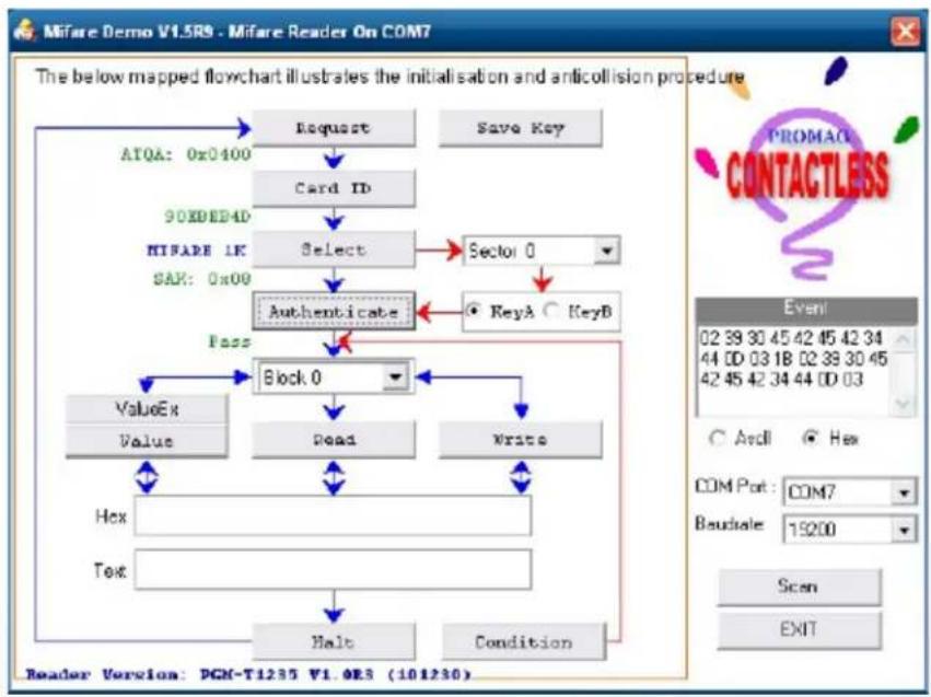
2-2 After finishing the AutoScan, Request box will be ready for the click and Reader Version will show on the position as marked. (Reader Version: PGM-T1235 V1.0R3 (101230) Place Mifare Card to the RFID reader area. Event Dialog window gets the data from the Mifare Card
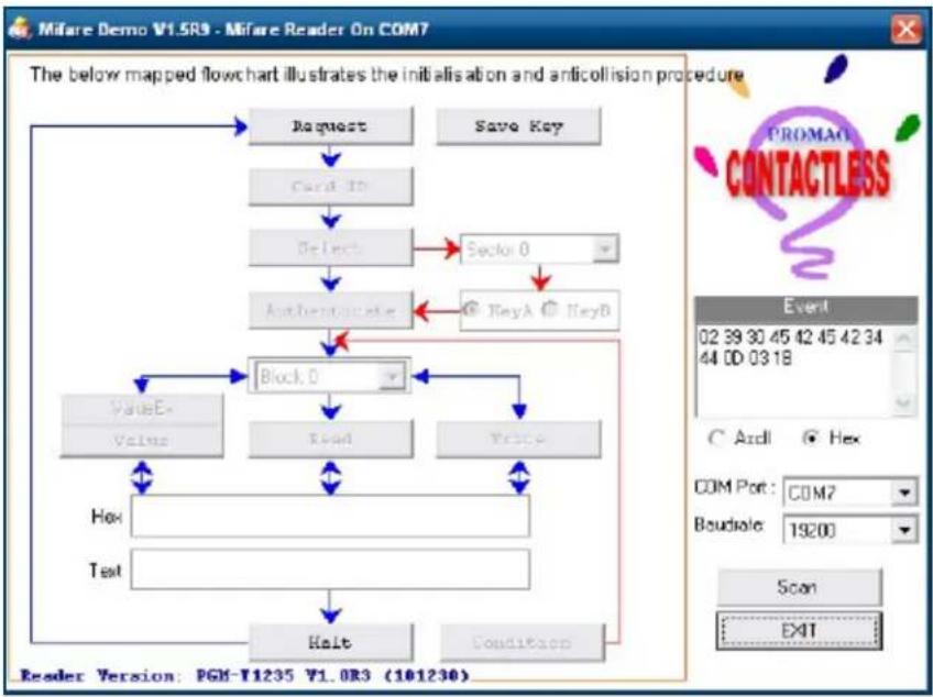
flowchart
graph TD
    A["Request"] --> B["Card ID"]
    B --> C["Select"]
    C --> D["Section 0"]
    D --> E["Authenticate"]
    E --> F["Block 0"]
    F --> G["Read"]
    G --> H["Price"]
    H --> I["Hox"]
    I --> J["Test"]
    J --> K["Halt"]
    K --> L["Condition"]
    L --> M["ValueE"]
    M --> N["Value"]
    N --> O["Block 0"]
    O --> P["Event: 02 39 30 45 42 45 42 34 44 00 03 18"]
    P --> Q["Com Port: COM7\nBoudsole: 19200"]
    Q --> R["Scan: EXIT"]
Close the RFID card to RFID reader
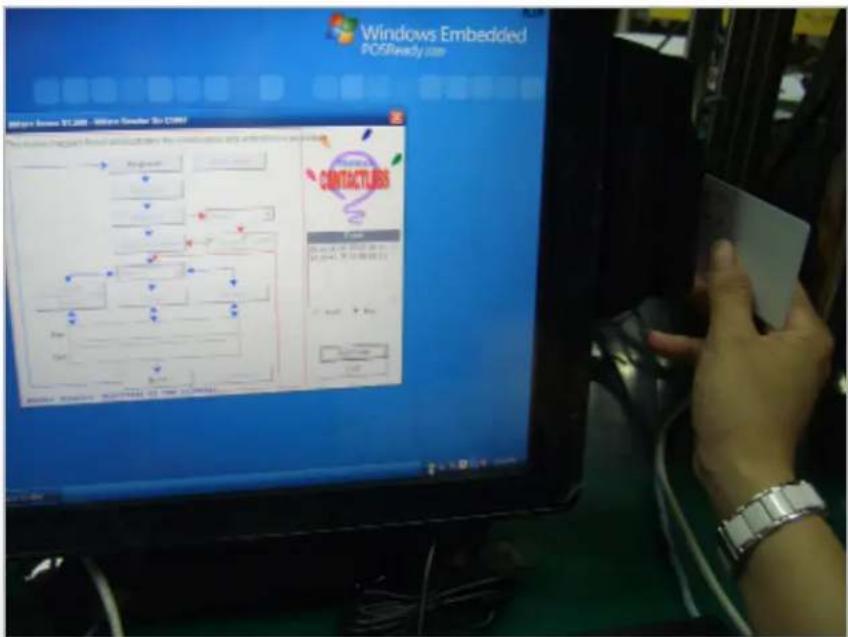
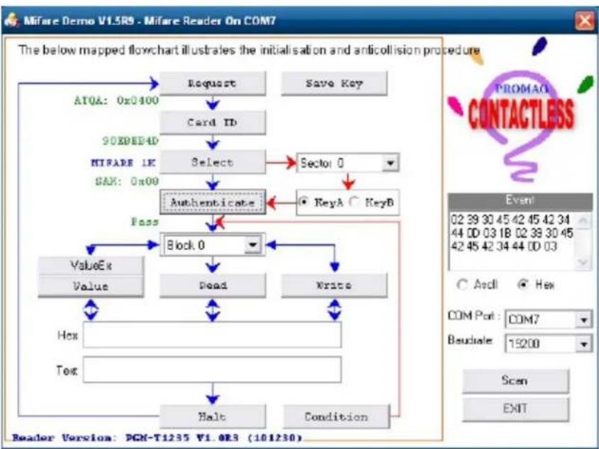
2-3 Card type will be recognized when you click "Request".
(Your Mifare card should be placed on the RFID reader area.)

flowchart
graph TD
    A["Request"] --> B["Card ID"]
    B --> C["Select"]
    C --> D["Authenticate"]
    D --> E["Block 0"]
    E --> F["Dead"]
    F --> G["Write"]
    G --> H["Hex"]
    G --> I["Text"]
    H --> J["Halo"]
    I --> K["Condition"]
    L["ATQA: 0x0400"] --> A
    M["908DEP4D"] --> N["MIFARE 1K"]
    O["SAR: 0x00"] --> P["Authenticate"]
    Q["KeyA"] --> R["KeyB"]
    S["Pass"] --> E
    T["ValueEx"] --> E
    U["Value"] --> E
    V["Hex"] --> H
    W["Text"] --> I
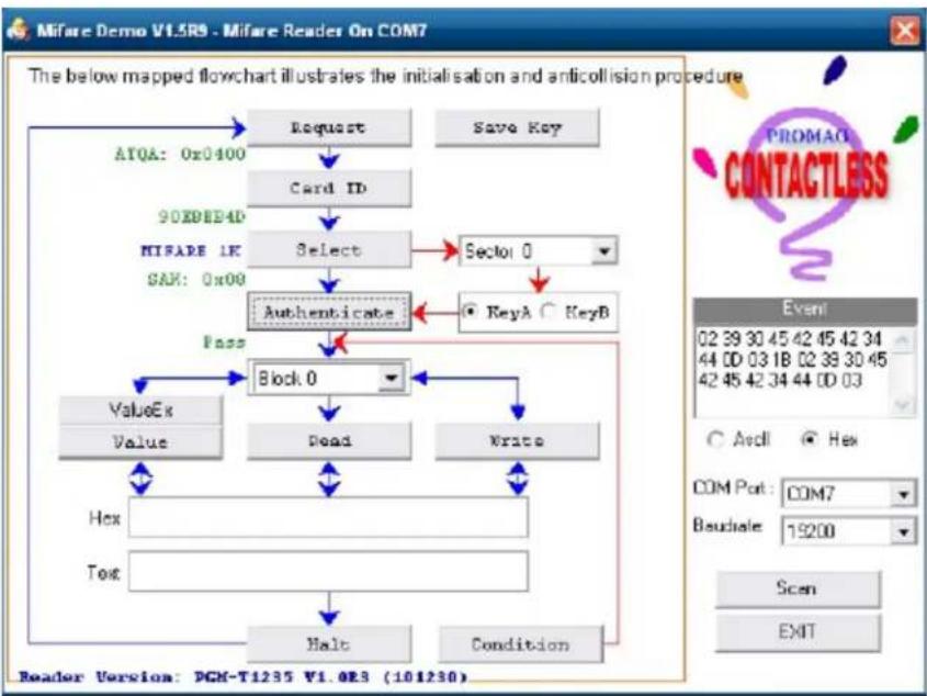
2-4 Card ID will be recognized when you click "Card ID".
flowchart
graph TD
    A["Request"] --> B["Card ID"]
    B --> C["Select"]
    C --> D["Authenticate"]
    D --> E["Block 0"]
    E --> F["Read"]
    E --> G["Write"]
    F --> H["Hex"]
    G --> I["Tex"]
    H --> J["Halt"]
    I --> K["Condition"]
    L["AYQA: 0x0400"] --> A
    M["90EDED4D"] --> N["HIFARE 1K"]
    N --> C
    O["SAX: 0x00"] --> C
    P["KeyA"] --> D
    Q["KeyB"] --> D
    R["Event"] --> S["COM Port : COM7"]
    T["Baudale: 19200"] --> U["Scan"]
    V["Reader Version: DGN-T1235 V1.0R5 (101230)"]
2-5 SAK will be read when you click "Select".
flowchart
graph TD
    A["Request"] --> B["Card ID"]
    B --> C["Select"]
    C --> D["Authenticate"]
    D --> E["Block 0"]
    E --> F["Read"]
    E --> G["Write"]
    F --> H["Hex"]
    G --> I["Text"]
    H --> J["Halt"]
    I --> K["Condition"]
    L["ATQA: 0x0400"] --> A
    M["SAX: 0x09"] --> C
    N["KEYA"] --> O["KeyB"]
    P["KEYB"] --> D
    Q["KEYB"] --> D
    R["KEYB"] --> D
    S["KEYB"] --> D
    T["KEYB"] --> E
    U["KEYB"] --> F
    V["KEYB"] --> G
    W["KEYB"] --> H
    X["KEYB"] --> I
    Y["KEYB"] --> J
    Z["KEYB"] --> K
    AA["KEYB"] --> L
    AB["KEYB"] --> M
    AC["KEYB"] --> N
    AD["KEYB"] --> O
    AE["KEYB"] --> P
    AF["KEYB"] --> Q
    AG["KEYB"] --> R
    AH["KEYB"] --> S
    AI["KEYB"] --> V
    AJ["KEYB"] --> W
    AK["KEYB"] --> X
    AL["KEYB"] --> Y
2-6 The result will show when you click "Authenticate"
flowchart
graph TD
    A["Request"] --> B["Card ID"]
    B --> C["Select"]
    C --> D["Authenticate"]
    D --> E["Block 0"]
    E --> F["Dead"]
    F --> G["Write"]
    G --> H["Hex"]
    H --> I["Text"]
    I --> J["Halt"]
    J --> K["Condition"]
    L["ATQA: 0x0400"] --> A
    M["90E8EP4D"] --> N["MIFARE 1K"]
    O["SAX: 0x09"] --> P["Authencitate"]
    Q["KeyA"] --> R["KeyB"]
5-1. VFD Specification
natural_image
Close-up of a dark, glossy electronic device with no visible text or symbols| General | Display Method Vaccum Fluorescent Display (Blue-green) | |
| Number of characters 40 (20 columns x 2 lines) | ||
| Brightness 500~1000 cd/m2 | ||
| Character front 5x7 dot matrix | ||
| Character type 95 Alphanumeric, 32 International Characters | ||
| Character size 6.75(H) x 3.75(W) mm | ||
| Dot size (X xY) 0.55x0.75 mm | ||
| Download charaters 9 chara ters | ||
| Height | 4.70" (120mm) with stand-alone base | |
| 9.80" (250mm) with base and 1 extension | ||
| Panel Dimension 75(H)x170(W)x50(D) mm | ||
| Pole Dimension Per support length: 130 mm | ||
| Base Dimension 33(H)x159.8(W)x100(D) mm | ||
| Viewing Angle Max. 90° | ||
| Horizontal Rotation Max. 355° | ||
| Weight Approx. 980 grams | ||
| Commands Mode | LD220, EPSON, AEDEX, UTC/S, UTC/P, ADM788, DSP800, CD5220, EMAX, LOGIC CONTROL, Ultimate | |
| Language Support | US English, Int'l English, Bosnia, Croatian, Czech, Danish, Dutch, Estonain, Faroese, Finnish, Flemish, French, Fr Canadian, German, Greek, Hebrew, Hungarian, Icelandic, Indonesian, Irish, Italian, Katakana, Lativian, Lithuanian, Norwegian, Polish, Portuguese, Romanian, Russian, Slo-vene, Slovak, Spanish, Swedish | |
| Interface | RS-232 (serial) / USB | |
| Reliability | Baud rate | Direct connection 9600 or 19,200 bps |
| Connection | MTBF | 30,000 hours |
| Power | Consumption | 5~12 VDC |
| Safety | EMC standards Safety standards | FCC, CE |
seTup sofTware guiDe
1 Power on, and waiting test page of EEPROM test, Baud rate, and Command page. And you may set up the customer display by "VFD_Setup.exe" Utility.
2. To execute "VFD_Setup.exe" for setup communication between display and Utility
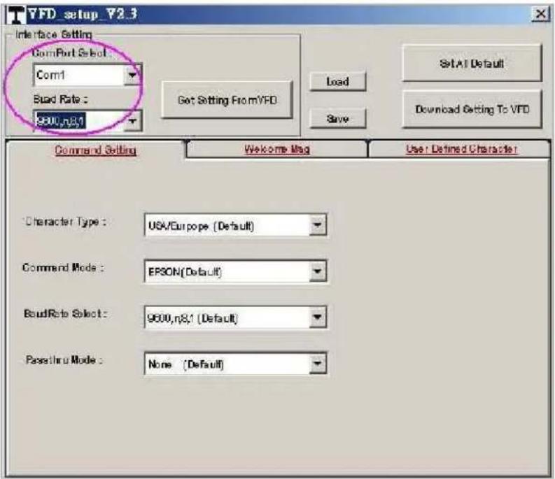
The Baud Rate will show on states page of the Utility (Note: You may check it when power on the display)
- "Get Setting From VFD" button To get all setting from the display and It'll refresh the "VFD_Setup.exe" utility
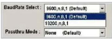
- "Character Type" / "Comand Mode" / "BaudRate Selcet" / "Passthru Mode" Please refer to Chapter 4-5 user manual
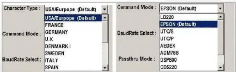
- "Set All Default" button To show default setting, the Default table is,
Character Type: USA
Command Type: EPSON
BaudRate Setting: 9600/n/8/1
Passthru Mode: None
Welcome msg line1: ***VFD DISPLAY***
Welcome msg line2: ***HAVE A NICE DAY AND THANK YOU***
- Welcome Msg
Welcome Msg line1 maximum 20 characters, line 2 maximum 20 characters, total of 40 characters.
a. ASCCII mode
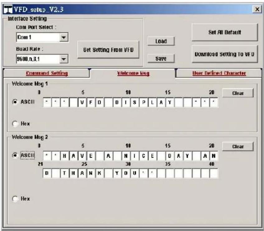
You can type the character by keyboard (0x20h\~0x7Fh), if you press clear icon, it will clear the all Msg characters on AP.
b. Hex mode
Hex mode can define the character from 0x20h to 0xFFh, the range 0x80\~0xFF
wich depends on the code page table.
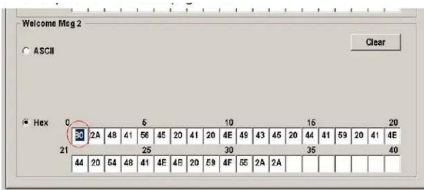
Like the first character (0x80) in default code page will show Ç on display
7. "Download setting to VFD" button
This button is to download the setting from VFD_Setup.exe to display.
*After success dialog „Download O.K.! Please restart!“ message popped up, you

8. "Save" button
To save user's setting in file, example: below picture to save file name as „Rename-Goodluck“ file set for Welcome Msg.
P.S: The default setting named „VFD.vfd“ which can't be made any setting change.
9. "Load" button
For saving your time, you could load any setting file which you made before the display. You must restart the display for enable the new settings.
i-Button Reader Configuration Utility
The i-Button Reader Configuration Utility is used to set up the output format of HID MSR
Installation
Below steps guide you how to install the Utility program.
- Insert the setup CD.
- Run the HID_MSR_PSW00003_V2_0_0.exe setup file that is located in the Software folder of CD.
- Follow the wizard to complete the installation.
Launching Program
Below steps guide you how to load the Utility program.
- From Start/Programs, click HID_MSR2 folder.
- Click MagStripe Card Reader Configuration Utility to launch the program.
- The utility program will detect the connected reader. If detected, all the input text boxes will be enabled.
- If the reader has not been connected to PC yet, please connect the reader and then click Refresh to get connected.
Configuration
Below is the main window of i-Button Utility program.
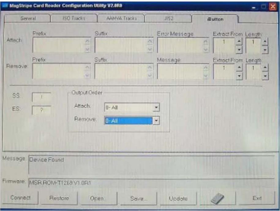
For the settings, there are:
- Prefix/Suffix: Defines the data string which you would like to append in front or end of the i-Button key string.
- Error Message: Indicates error message when i-Button key read fail.
- Message: Indicates message when i-Button key read correctly.
- SS/ES : Define Start and End sentinel byte for the i-Button ID string.
- Length : i-Button ID length request from 0\~16.
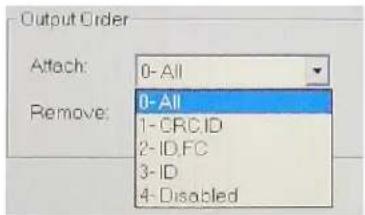
- Output order: 4 format could be select at Attach /Remove i-Button ID.
Update Settings
Once complete the settings, click Update to update the settings to connected HID MSR reader.
Save Settings
To save the settings to a file, click Save; specify the file name and location to be saved.
Open Settings
To load pre-saved settings, click Open, specify the settings file, and then click OK to load into program.
Restore MSR Reader Settings
To load restore settings of connected MSR reader, click Restore ES2: End sentinel for track.
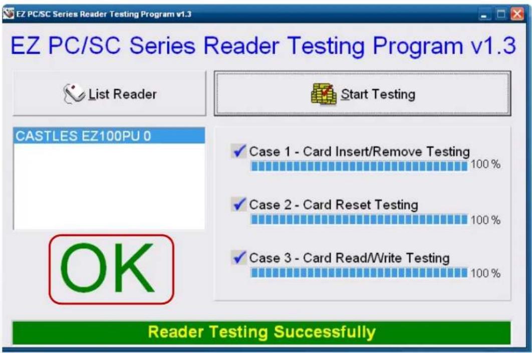
Installation and Testing of Smart Card Reader
- Check smart card reader be detected by "Device manager".
- Install the SCR driver.
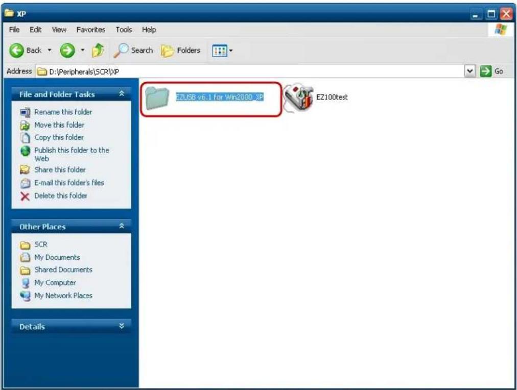
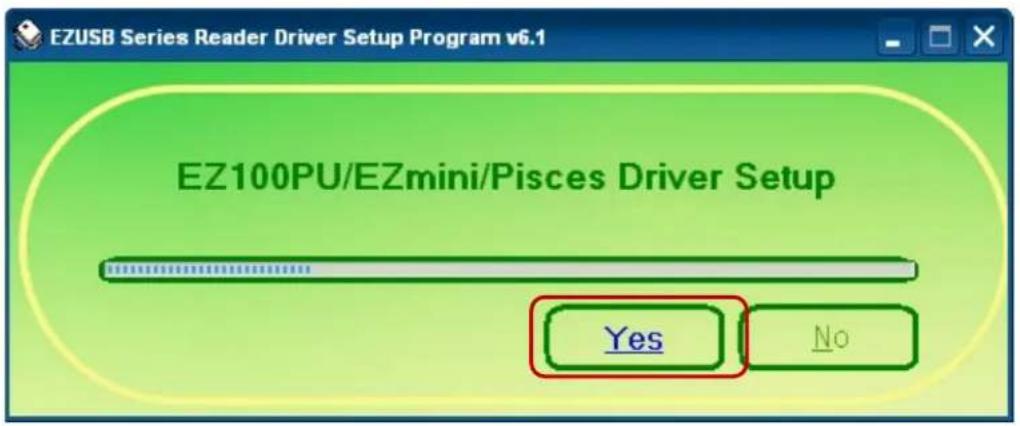
3. Run Setup.exe.
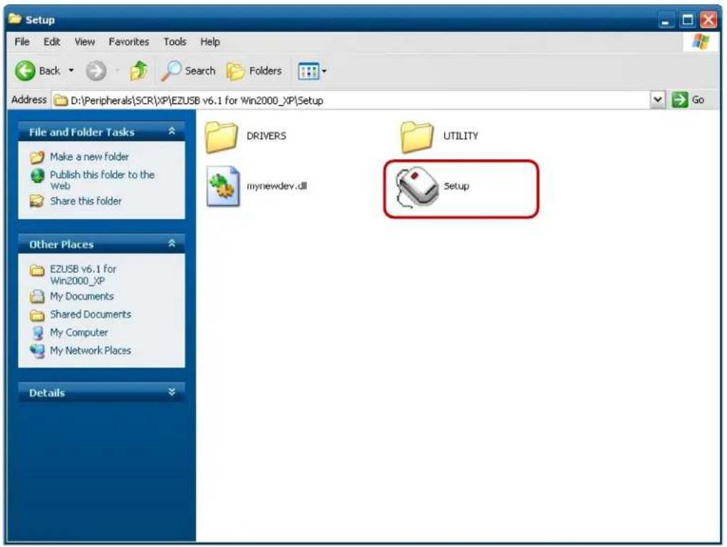
4. Click "Yes".
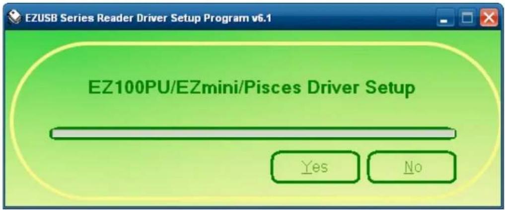
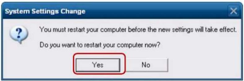
- Restart systems.
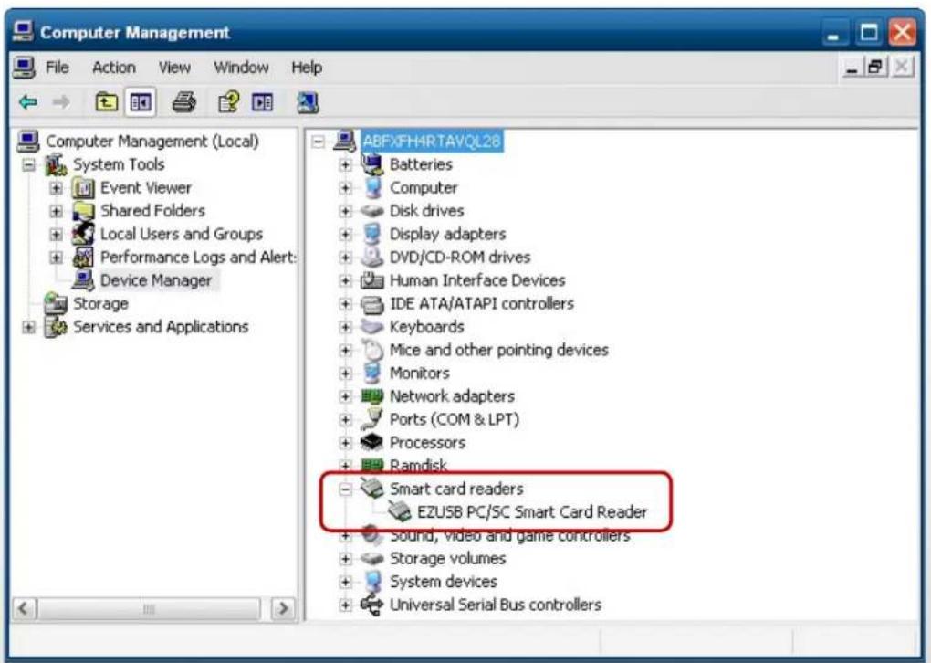
- Check SCR reader in Device Manager.
- Run the testing program - EZ100test.
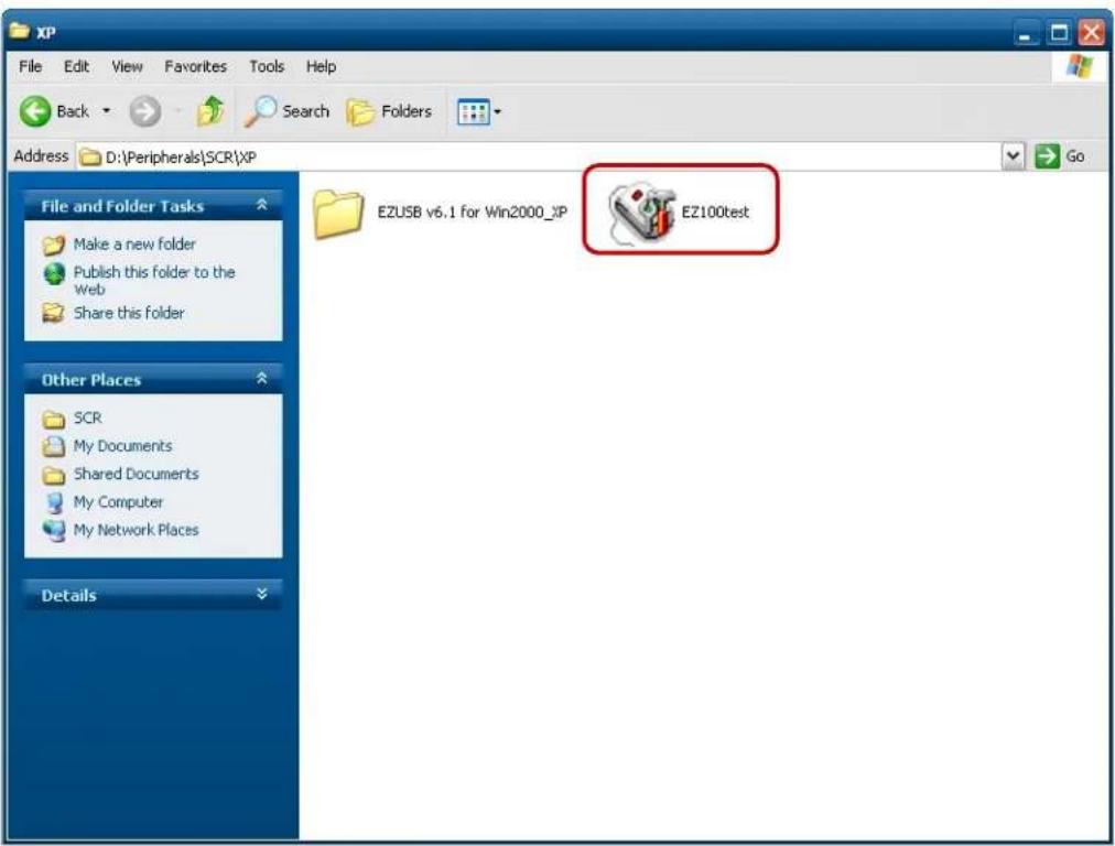
- Confirm that SCR can be detected by the testing program, then run the program - the Start Testing.
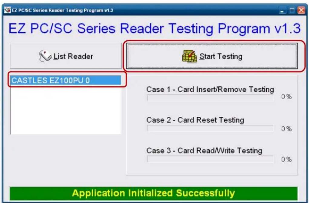
- Follow dialog boxes displayed to remove and insert card.


- After finishing the testing, the dialog box will show "oK".
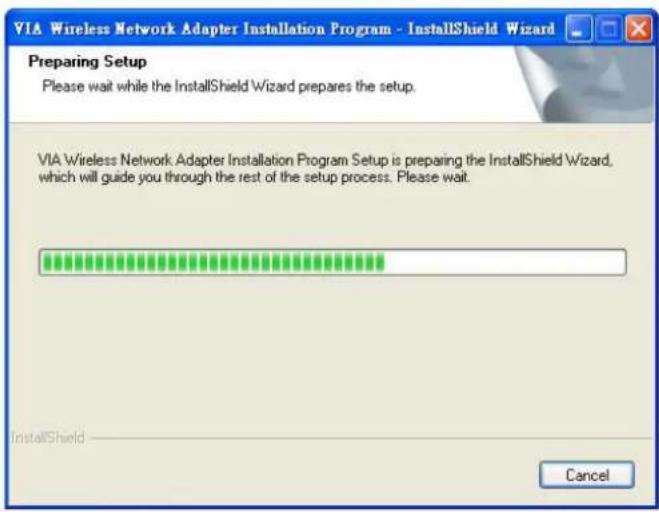
wi-fi
- Install the Wi-Fi driver.

9271_Windows_Driver_V1.3_0.0_x86.exe
- Run Setup.exe.

9271_Wind...
6-1. BIOS/Utility setup
Press /
| BIOS Information BIOS Vendor Core Version Compliancy Project Version Build Date and Time | American Megatrends 4.6.4.1 UEFI 2.1 CI00B 0.01 x64 03/19/2012 19:16:26 | Choose the system default language |
| Manufacture Name Product Name BIOS Version | Colometrics P2300 V:8.2.00-03192012 | |
| Memory Information Total Memory | 2048 MB (DDR3 1067) | |
| System Language | [English] | +: Select Screen ↑↓: Select Item Enter: Select +/-: Change Opt. F1: General Help F2: Previous Values F3: Optimized Defaults F4: Save & Exit ESC: Exit |
| System Date System Time | [Thu 04/26/2012] [13:34:02] | |
| Access Level | Administrator |
Please press /
Date and Time
The Date and Time items show the current date and time on the computer. If you are running a Windows OS, these items are automatically updated whenever you make changes to the Windows Date and Time Properties utility.
WARNING
Setting the wrong values in the sections below may cause the system to malfunction. Make sure that the settings made are compatible with the hardware.
6-2. Advanced
Use the Advanced menu to configure the CPU and peripheral devices through the following sub-menus:
![Aptio Setup Utility - Copyright (C) 2011 American Megatrends, Inc. Main Advanced Chipset Boot Security Save & Exit Legacy OpROM Support Launch PXE OpROM [Enabled] ▶ ACPI Settings ▶ S5 RTC Wake Settings ▶ CPU Configuration ▶ SATA Configuration ▶ Intel IGD SHSCI OpRegion ▶ USB Configuration ▶ IT8783F Super IO Configuration ▶ IT8783F H/W Monitor Enable or Disable Boot Option for Legacy Network Devices. ++: Select Screen ↑↓: Select Item Enter: Select +/-: Change Opt. F1: General Help F2: Previous Values F3: Optimized Defaults F4: Save & Exit ESC: Exit](/content/2026/05/1058453/images/b62cbd754f37f3d950299f0a490a7144b912109127cb87337e86caa89eba4c05.jpg)
6-2.1 ACPI Configuration
The ACPI Configuration menu configures the Advanced Configuration and Power Interface (ACPI) options
![Aptio Setup Utility - Copyright (C) 2011 American Megatrends, Inc. Advanced ACPI Settings Enable ACPI Auto Configuration [Disabled] Enable Hibernation [Enabled] ACPI Sleep State [S3 (Suspend to RAM)] Enables or Disables BIOS ACPI Auto Configuration. +: Select Screen ↑↓: Select Item Enter: Select +/-: Change Opt. F1: General Help F2: Previous Values F3: Optimized Defaults F4: Save & Exit ESC: Exit](/content/2026/05/1058453/images/15678247161b322184d6ba879d9bef609b847907cf4075430f869a564dc989e9.jpg)
ACPI Sleep State
Use the ACPI Sleep State option to specify the sleep state the system enters when it is not being used.
1. Suspend Disabled
2. S1 (CPU Stop Clock)
DEFAULT The system enters S1 (POS) sleep state. The system appears off. The CPU is stopped; RAM is refreshed; the system is running in a low power mode.
3. S3 (Suspend to RAM)
The caches are flushed and the CPU is powered off. Power to the RAM is maintained. The computer returns slower to a working state, but more power is saved.
6-2.2 S5 RTC Wake Settings
Enable or disable system wake on alarm event. When enabled, system will wake on the hr::min::sec specified.
![Aptio Setup Utility - Copyright (C) 2011 American Megatrends, Inc. Advanced Wake system with Fixed Time [Disabled] Wake system with Dynamic Time [Disabled] Enable or disable System wake on alarm event. When enabled, System will wake on the hr::min::sec specified +: Select Screen +: Select Item Enter: Select +/-: Change Opt. F1: General Help F2: Previous Values F3: Optimized Defaults F4: Save & Exit ESC: Exit](/content/2026/05/1058453/images/ab694476438ab5cc2f17d10f88bc36704b59c7054fb60dd52989f0aa2ae55156.jpg)
6-2.3 CPU Configuration
Use the CPU Configuration menu to enter the CPU Information submenu or setup Intel CPU parameter.
| CPU Configuration | Socket specific CPU Information | |
| Socket 0 CPU Information | ||
| CPU Speed 64-bit | 2500 MHz Supported | |
| Active Processor Cores Limit CPUID Maximum Execute Disable Bit Hardware Prefetcher Adjacent Cache Line Prefetch Intel Virtualization Technology Power Technology Factory long duration power limit Long duration power limit Factory long duration maintained Long duration maintained Recommended short duration power 1 Short duration power limit | [All] [Disabled] [Enabled] [Enabled] [Disabled] [Energy Efficient] | +: Select Screen ↑↓: Select Item Enter: Select +/-: Change Opt. F1: General Help F2: Previous Values F3: Optimized Defaults F4: Save & Exit ESC: Exit |
| 65 Watts 0 1000 ms 0 1.25 * Long Duration 0 | ||
6-2.4 SATA Configuration
Use the SATA Configuration menu to change and/or set the configuration of the SATA devices installed in the system.
| SATA Configuration | (1) IDE Mode. (2) AHCI Mode. (3) RAID Mode. | |
| SATA Mode | [AHCI Mode] | |
| Aggressive Link Power Management | [Enabled] | |
| SATA Port0 | Not Present | |
| Staggered Spin-up | [Disabled] | |
| External SATA Port | [Disabled] | |
| Hot Plug | [Disabled] | |
| SATA Port1 | Not Present | |
| Staggered Spin-up | [Disabled] | |
| External SATA Port | [Disabled] | |
| Hot Plug | [Disabled] | |
| +: Select Screen ↑↓: Select Item Enter: Select +/-: Change Opt. F1: General Help F2: Previous Values F3: Optimized Defaults F4: Save & Exit ESC: Exit | ||
SATA Mode
Use the SATA Mode option to configure SATA devices as normal IDE devices.
Disable Disables SATA devices.
IDE Mode Configures SATA devices as normal IDE device.
RAID Mode Configures SATA devices as RAID device.
6-2.5 Intel IGD SWSCI OpRegion Configuration
Use the Configuration menu to change and/or set the configuration of the internal graphics devices installed in the system.
![Aptio Setup Utility - Copyright (C) 2011 American Megatrends, Inc. Advanced Intel IGD SHSCI OpRegion Configuration DVMT Mode Select [DVMT Mode] DVMT/FIXED Memory [256MB] IGD - Boot Type [VBIOS Default ] LCD Panel Type [1024x768 LVDS] ++: Select Screen ↑↓: Select Item Enter: Select +/-: Change Opt. F1: General Help F2: Previous Values F3: Optimized Defaults F4: Save & Exit ESC: Exit](/content/2026/05/1058453/images/e02cf1045b70660b34f9d40862cb5d44492b31ef697412e8772363df397adafd.jpg)
DVMT Mode
Use the DVMT Mode option to configure internal graphics device.
DVMT/FIXED Memory
Use the option to configure memory size of internal graphics device.
6-2.6 USB Configuration
Use the USB Configuration menu to read USB configuration information and configure the USB settings.
| Aptio Setup Utility - Copyright (C) 2011 American Megatrends, Inc. Advanced | |
| USB Configuration USB Devices: 1 Keyboard, 2 Hubs Legacy USB Support [Enabled] EHCI Hand-off [Disabled] Port 60/64 Emulation [Enabled] USB hardware delays and time-outs: USB transfer time-out [20 sec] Device reset time-out [20 sec] Device power-up delay [Auto] | Enables Legacy USB support. AUTO option disables legacy support if no USB devices are connected. DISABLE option will keep USB devices available only for EFI applications. |
| +: Select Screen ↑↓: Select Item Enter: Select +/-: Change Opt. F1: General Help F2: Previous Values F3: Optimized Defaults F4: Save & Exit ESC: Exit | |
USB Devices
The USB Devices Enabled field lists the USB devices that are enabled on the system.
Legacy USB Support [Enabled]
Use the Legacy USB Support BIOS option to enable USB mouse and USB keyboard support. Normally if this option is not enabled, any attached USB mouse or USB keyboard does not become available until a USB compatible operating system is fully booted with all USB drivers loaded. When this option is enabled, any attached USB mouse or USB keyboard can control the system even when there is no USB driver loaded onto the system.
Disabled Legacy USB support disabled
Enabled Legacy USB support enabled
6-2.7 IT8783F Super IO Configuration
Use the Super IO Configuration menu to set or change the configurations for parallel ports and serial ports.
| Aptio Setup Utility - Copyright (C) 2011 American Magatrends, Inc. Advanced | |
| IT8783F Super IO Configuration IT8783F Super IO Chip IT8783F ► Serial Port 1 Configuration ► Serial Port 2 Configuration ► Serial Port 3 Configuration ► Serial Port 4 Configuration ► Parallel Port Configuration | Set Parameters of Serial Port O (COMA) |
| +: Select Screen ↑↓: Select Item Enter: Select +/-: Change Opt. F1: General Help F2: Previous Values F3: Optimized Defaults F4: Save & Exit ESC: Exit | |
6-2.8 Serial Port n Configuration
Use the Serial Port n Configuration menu to configure the serial port n.
| Serial Port 1 Configuration Serial Port [Enabled] Device Settings IO=3F8h; IRQ=4; Change Settings [Auto] | Enable or Disable Serial Port (COM) |
| +: Select Screen ↑↓: Select Item Enter: Select +/-: Change Opt. F1: General Help F2: Previous Values F3: Optimized Defaults F4: Save & Exit ESC: Exit |
Serial Port [Enabled]
Use the Serial Port option to enable or disable the serial port.
Disabled Disable the serial port
Enabled Enable the serial port
Change Settings [Auto]
Use the Change Settings option to change the serial port IO port address and interrupt address.
Auto The serial port IO port address and interrupt address are automatically detected.
6-2.9 parallel port Configuration
Use the Parallel Port Configuration menu to configure the parallel port.
![Aptio Setup Utility - Copyright (C) 2011 American Megatrends, Inc. Advanced Parallel Port Configuration Parallel Port Device Settings Change Settings Device Mode [Enabled] IO=378h; IRQ=5; [Auto] [Standard Parallel ...] Enable or Disable Parallel Port (LPT/LPTE) +: Select Screen ↑↓: Select Item Enter: Select +/-: Change Opt. F1: General Help F2: Previous Values F3: Optimized Defaults F4: Save & Exit ESC: Exit](/content/2026/05/1058453/images/028800874305f4fa76d65babb7b447895dc2bfc7eef12cada3bd3dde8c16debd.jpg)
6-2.10 h/w monitor
The H/W Monitor menu shows the operating temperature and fan speeds.
| Aptio Setup Utility - Copyright (C) 2011 American Megatrends, Inc. Advanced | |
| Pc Health Status | |
| System temperature1 : +57 % Fan1 Speed : 3792 RPM | |
| ++: Select Screen ↑↓: Select Item Enter: Select +/-: Change Opt. F1: General Help F2: Previous Values F3: Optimized Defaults F4: Save & Exit ESC: Exit | |
6-3. Chipset
Use the Chipset menu to access the Northbridge and Southbridge configuration menus.
WARNING
Setting the wrong values for the Chipset BIOS selections in the Chipset BIOS menu may cause the system to malfunction.
| North Bridge South Bridge HE Subsystem | North Bridge Parameters |
| +: Select Screen 1↓: Select Item Enter: Select +/-: Change Opt. F1: General Help F2: Previous Values F3: Optimized Defaults F4: Save & Exit ESC: Exit |
6-3.1 Northbridge Configuration
Use the Northbridge Chipset Configuration menu to configure the Northbridge chipset.
| Memory Information | Low MMIO resources align at 64MB/1024MB | |
| Total Memory | 2048 MB (DDR3 1067) | |
| Memory Slot0 | 2048 MB (DDR3 1067) | |
| Memory Slot1 | 0 MB (DDR3 1067) | |
| Memory Slot2 | 0 MB (DDR3 1067) | |
| Memory Slot3 | 0 MB (DDR3 1067) | |
| Low MMIO Align | [1024M] | |
| DMI Gen2 | [Enabled] | |
| VT-d | [Disabled] | |
| Initiate Graphic Adapter | [PEG/IGD] | +: Select Screen ↑↓: Select Item Enter: Select +/-: Change Opt. F1: General Help F2: Previous Values F3: Optimized Defaults F4: Save & Exit ESC: Exit |
| IGD Memory | [64M] | |
| Render Standby | [Enabled] | |
| IGD Multi-Monitor | [Disabled] | |
| PCI Express Port | [Auto] | |
| PEG Force Gen1 | [Disabled] | |
| Detect Non-Compliance Device | [Disabled] | |
| MRC Message Print | [Disabled] |
Initiate Graphic Adapter [PEG/IGD]
Use the Initiate Graphic Adapter option to select the graphics controller used as the primary boot device. Select either an integrated graphics controller (IGD) or a combination of PCI graphics controller, a PCI express (PEG) controller or an IGD.
Configuration options are listed below:
IGD
PCI/IGD
PCI/PEG
PEG/IGD DEFAULT
PEG/PCI
IGD Memory [64 M]
Use the IGD Memory option to specify the amount of system memory that can be used by the internal graphics device.
6-3.2 southbridge Configuration
Use the Southbridge Configuration menu to configure the Southbridge chipset.
| SB Chipset Configuration SMBus Controller | [Enabled] |
| Restore AC Power Loss | [Power Off] |
| Serial Port 1 Voltage Select | [STD] |
| Serial Port 2 Voltage Select | [STD] |
| Audio Configuration Azalia HD Audio | [Enabled] |
| PCI Express Ports Configuration USB Configuration |
serial port 1/2 Voltage select [sTD]
Select „COM1/2 PIN9 Function“ and press
| ITEM Option Descriptions | ||
| COM1 PIN9 Function COM1/2 Pin9 select PING function5V | ||
| COM2 PIN9 Function COM1/2 Pin9 select 5V/12V function12V |
6-3.3 ME Subsystem
Use the ME Subsystem menu to configure the Intel® Management Engine (ME) configuration options.
![Aptio Setup Utility - Copyright (C) 2011 American Megatrends, Inc. Chipset Intel ME Subsystem Configuration ME Version 7.1.20.1119 ME Subsystem [Enabled] ME Temporary Disable [Disabled] End of Post Message [Enabled] Execute MEBx [Enabled] MEBx Mode [Normal] ► Integrated Clock Chip Configuration ME Subsystem Help +: Select Screen ↑↓: Select Item Enter: Select +/-: Change Opt. F1: General Help F2: Previous Values F3: Optimized Defaults F4: Save & Exit ESC: Exit](/content/2026/05/1058453/images/0d894e1557aeaebe3ac2dd826e77fcc445d39451ef820161cee40441ad88a2a8.jpg)
6-3.4 Boot
Use the Boot menu to configure system boot options.
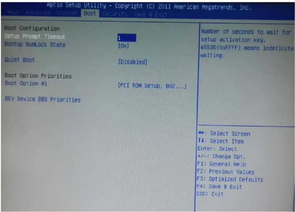
Bootup NumLock State [On]
Use the Bootup NumLock State BIOS option to specify if the number lock setting must be modified during boot up.
Quiet Boot [Enabled]
Use the Quiet Boot BIOS option to select the screen display when the system boots.
6-3.4 Security
Use the Security menu to set system and user passwords.
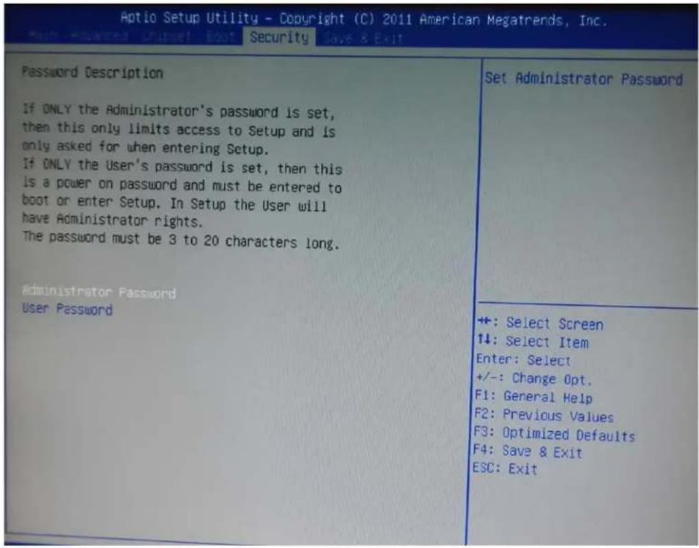
Administrator Password
Use the Administrator Password to set or change an administrator password.
User Password
Use the User Password to set or change a user password.
6-3.5 Save & Exit
Use the Save & Exit menu to load default BIOS values, optimal failsafe values and to save configuration changes.
| Save Changes and ExitDiscard Changes and ExitSave Changes and ResetDiscard Changes and Reset | Exit system setup after saving the changes. |
| Save OptionsSave ChangesDiscard Changes | |
| Restore DefaultsSave as User DefaultsRestore User Defaults | |
| Boot OverridePCI ROM Setup, BO2 DOO FO | +: Select Screen↑↓: Select ItemEnter: Select+/-: Change Opt.F1: General HelpF2: Previous ValuesF3: Optimized DefaultsF4: Save & ExitESC: Exit |
| Launch EFI Shell from filesystem device |
LCD Surface Cleaning
1. How to clean the LCD surface properly?
Do not spray any liquids on the LCD screen directly, and do not use paper towels, this can cause the LCD screen to become scratched.
Always apply the solution to your cloth first, not directly to the parts you are cleaning. You want to avoid dripping the solution directly into your computer or laptop.
Stroke the cloth across the display in one direction, moving from the top of the display to the bottom.
2. What are some of the basic supplies needed to clean an LCD screen?
A soft cotton cloth. When cleaning the LCD screen it is important to use a soft cotton cloth, rather than an old rag. Some materials, such as paper towels, could cause scratches and damage the LCD screen.
Solution of water and isopropyl alcohol. This solution can be used along with the soft cotton cloth.
Computer wipes. Only use these if they specifically state on the package they are designed for LCD laptop screens. Computer wipes can come in handy for fast clean-ups or when you want to avoid mixing up a cleaning solution yourself.
3. What types of cleaners are acceptable?
- Water
• Vinegar (mixed with water) - Isopropyl Alcohol
NOTICE: The following cleaners are unacceptable:
- Acetone
- Ethyl alcohol
- Ethyl acid
- Ammonia
- Methyl chloride
CE Notice
This device complies with the requirements of the CE directive.
FCC Notice
This equipment has been tested and found to comply with the limits for a Class B digital device, pursuant to Part 15 of the FCC rules. These limits are designed to provide reasonable protection against harmful interference in a residential installation. This equipment generates, uses and can radiated radio frequency energy and, if not installed and used in accordance with the instructions, may cause harmful interference to radio communications. However, there is no guarantee that interference will not occur in a particular installation. If this equipment does cause harmful interference to radio or television reception, which can be determined by turning the equipment off and on, the user is encouraged to try to correct the interference by one or more of the following measures:
- Reorient or relocate the receiving antenna.
- Increase the separation between the equipment and receiver.
- Connect the equipment into an outlet on a circuit different from that to which the receiver is connected.
- Consult the dealer or an experienced radio/TV technician for help.
Shielded interface cables must be used in order to comply with emission limits.
Changes or modifications not expressly approved by the party responsible for compliance could void the user's authority to operate the equipment.
WEEE Notice
This appliance is labelled in accordance with European Directive 2002/96/EC concerning waste electrical and electronic equipment (WEEE). The Directive determines the framework for the return and recycling of used appliances as applicable throughout the European Union. This label is applied to various products to indicate that the product is not to be thrown away, but rather reclaimed upon end of life per this Directive.
- Table of ConTenTs
- CopyrightT 4
- safeTy insTruCTions 5
- paCking lisT 6
- sysTem View 7
- pin Definition 11
- rear i/o inTerfaCe 13
- sysTem assembly & Disassembly 15
- DeViCe DriVer insTallaTion 26
- inTernal VfD (opTional) 58
- seTup softWare guiDe 59
- i-buTTon reaDer ConfiguraTion uTiliTy 62
- bios/uTiliTy seTup 71
- COPYRIGHT
- Copyright 2010 Publishing. All Rights Reserved.
- SAFETY INSTRUCTIONS
- Lithium Battery Caution:
- PACKING LIST
- 1-1. Standard Accessories
- 1-2. Optional Accessories
- 2-1. Rear View Standard
- Item
- 2-4. Touch Panel Life Test Condition
- 2-4.1 Pointing life test
- 2-4.2 Hand Writing test
- PIN DEFINITION
- Parallel J7
- VFD Connector CN9
- Mic
- Line-out J3
- Speaker SP1
- LVDS CN 2
- Inverter CN14
- Extra USB CN13
- COM1' COM2' COM3 port
- VGA port
- 3-1. HDD
- 3-2. CF-Card
- 3-3. MSR
- 3-4. Cable Cover
- 3-5. 8"/15" 2nd Display
- 3-6. 8" 2nd Display
- 3-7. 1D / 2D / iButton with RFID Module
- 4-1. Resistive Type Touch Panel
- Click "Next"
- Click "Next"
- Click "Next"
- Select "None", Click "Next".
- Click "Next"
- 4-2. MagStripe Card Reader Configuration Utility
- Installation
- Launching Program
- Configuration
- for the settings, there are:
- Prefix/Suffix
- ISO
- Decode Mode
- Track Data Filtering
- Switch Output Order
- Update Settings
- 4-3. Fingerprint Reader
- 4-4. rfiD
- install RFID utility
- Click "Next"
- Click "Giga-TMS" & "Next"
- Click "Next"
- Click "Next"
- 2-3 Card type will be recognized when you click "Request".
- 2-4 Card ID will be recognized when you click "Card ID".
- 5-1. VFD Specification
- seTup sofTware guiDe
- "Download setting to VFD" button
- "Save" button
- "Load" button
- i-Button Reader Configuration Utility
- Save Settings
- Open Settings
- Restore MSR Reader Settings
- Installation and Testing of Smart Card Reader
- Run Setup.exe.
- Click "Yes".
- wi-fi
- 6-1. BIOS/Utility setup
- Date and Time
- WARNING
- 6-2. Advanced
- 6-2.1 ACPI Configuration
- ACPI Sleep State
- Suspend Disabled
- S1 (CPU Stop Clock)
- S3 (Suspend to RAM)
- 6-2.2 S5 RTC Wake Settings
- 6-2.3 CPU Configuration
- 6-2.4 SATA Configuration
- SATA Mode
- 6-2.5 Intel IGD SWSCI OpRegion Configuration
- DVMT Mode
- DVMT/FIXED Memory
- 6-2.6 USB Configuration
- USB Devices
- Legacy USB Support [Enabled]
- 6-2.7 IT8783F Super IO Configuration
- 6-2.8 Serial Port n Configuration
- Serial Port [Enabled]
- Change Settings [Auto]
- 6-2.9 parallel port Configuration
- 6-2.10 h/w monitor
- 6-3. Chipset
- 6-3.1 Northbridge Configuration
- Initiate Graphic Adapter [PEG/IGD]
- IGD Memory [64 M]
- 6-3.2 southbridge Configuration
- serial port 1/2 Voltage select [sTD]
- 6-3.3 ME Subsystem
- 6-3.4 Boot
- Bootup NumLock State [On]
- Quiet Boot [Enabled]
- 6-3.4 Security
- Administrator Password
- User Password
- 6-3.5 Save & Exit
- LCD Surface Cleaning
- How to clean the LCD surface properly?
- What are some of the basic supplies needed to clean an LCD screen?
- What types of cleaners are acceptable?
- NOTICE: The following cleaners are unacceptable:
- CE Notice
- FCC Notice
- WEEE Notice
Brand : Colormetrics
Model : P2300
Category : Cash register