P4100 - Cash register Colormetrics - Free user manual and instructions
Find the device manual for free P4100 Colormetrics in PDF.

| Product Type | Cash Register (POS System) |
| Brand | Colormetrics |
| Model | P4100 |
| Processor | Intel Celeron J1900 Quad Core 2.0 GHz |
| Memory | 1x SO-DIMM DDR3L up to 8 GB |
| Storage | 2.5" SATA HDD/SSD, M.2 (22/2) 1x SSD |
| Display Size | 15-inch TFT LED LCD |
| Display Resolution | 1024 x 768 pixels |
| Brightness | 350 cd/m² |
| Touch Panel | 5-wire Resistive or Projected Capacitive |
| Network | 1x RJ45 10/100/1000 Base-T |
| USB Ports | 4x USB 2.0, 1x USB 3.0 |
| Serial Ports | 4x RJ45 (Powered COM ports with +5V/+12V) |
| I/O Options | Type A, B, C, D (e.g., additional USB, RS232, Parallel, 24V Powered USB) |
| Power Adapter | AC 19V 60W/90W/150W (depending on configuration) |
| Cooling | Fanless thermal solution |
| Dimensions (W x D x H) | 374 x 301 x 37 mm (without stand) |
| Operating Temperature | 0°C to 35°C |
| Storage Temperature | -20°C to 60°C |
| Storage Humidity | 20% to 80% non-condensing |
| Cleaning LCD | Use soft cotton cloth with water/isopropyl alcohol; avoid paper towels, acetone, ammonia |
| Safety Features | Lithium battery caution, surge protection, CE and WEEE compliant |
Frequently Asked Questions - P4100 Colormetrics
User questions about P4100 Colormetrics
0 question about this device. Answer the ones you know or ask your own.
Ask a new question about this device
Download the instructions for your Cash register in PDF format for free! Find your manual P4100 - Colormetrics and take your electronic device back in hand. On this page are published all the documents necessary for the use of your device. P4100 by Colormetrics.
USER MANUAL P4100 Colormetrics
natural_image
Exterior view of a modern office desk monitor with a black frame and 'Colormetrics' logo on the front panel (no additional text or symbols visible)COPYRIGHT SAFETY INSTRUCTIONS
Copyright 2015 Publishing. All Rights Reserved.
This manual, software and firmware described in it are copyrighted by their respective owners and protected under the laws of the Universal Copyright Convention. You may not reproduce, transmit, transcribe, store in a retrieval system, or translate into any language, in any form or by any means, electronic, mechanical, magnetic, optical, chemical, biological, molecular, manual, or otherwise, any part of this publication without the express written permission of the publisher.
All products and trade names described within are mentioned for identification purpose only. No affiliation with or endorsement of the manufacturer is made or implied. Product names and brands appearing in this manual are registered trademarks of their respective companies.
The information published herein has been checked for accuracy as of publishing time. No representation or warranties regarding the fitness of this document for any use are made or implied by the publisher. We reserve the right to revise this document or make changes in the specifications of the product described therein at any time without notice and without obligation to notify any person of such revision or change.
- Read these instructions carefully. Keep these instructions for future reference.
- Please disconnect this equipment from AC outlet before cleaning. Don't use liquid or sprayed detergent for cleaning. Use moisture sheet or cloth for cleaning.
- Please keep this equipment from humidity.
- Lay this equipment on a reliable surface when install. A drop or fall could cause injury.
- Make sure power cord such a way that people cannot step on it. Do not place anything over the power cord.
- All cautions and warnings on the equipment should be noted.
- If the equipment is not used for long time, disconnect the equipment from main to avoid being damaged by transient over voltage.
- Never pour any liquid into opening, this could cause fire or electrical shock.
- If one of the following situations arises, get the equipment checked by a service personnel:
a. The power cord or plug is damaged.
b. Liquid has penetrated into the equipment.
c. The equipment has been exposed to moisture.
w. The equipment does not work well or you can not get it work according to user manual.
e. The equipment has dropped and damaged. - Do not leave this equipment in an environment unconditioned, storage temperature below -20°C or above 60°C, it may damage the equipment.
- Unplug the power cord when doing any service or adding optional kits.
Lithium Battery Caution:
Danger of explosion can happen if the battery is incorrectly replaced, Replace only the original or equivalent type recommended by the manufacture. Dispose used batteries according to the manufacture's instructions.
Do not remove the cover, and ensure no user serviceable components are inside. Take the unit to the service center for service and repair.
TABLE OF CONTENTS
COPYRIGHT 2
SAFETY INSTRUCTIONS 3
1 PACKING LIST 5
1-1. Standard Accessories 5
1-2. Optional Accessories 5
2 SYSTEM VIEW 6
2-1. Rear View (I/O Type A) 6
2-2. Back View 6
2-3. Specification 7
2-4. Internal Layout 8
3 PIN DEFINITION 9
4 REAR I/O INTERFACE 12
5 SYSTEM ASSEMBLY & DISASSEMBLY 13
5-1. HDD 13
5-2. Memory 14
5-3. MSR/i-Button/RFID 15
5-4. VFD/8"/10"/15" 2nd Display 16
5-5. 1D/2D Barcode scanner 19
6 DEVICE DRIVER INSTALLATION 20
6-1. Resistive Type Touch Panel and P-CAP 20
6-2. MagStripe Card Reader Configuration Utility 26
6-3.RFID 35
6-4. USB 2nd Display 41
6-5. Configuration Utility of i-Button Reader 43
6-6. VFD VD1220 49
7 BIOS/UTILITY SETUP 54
7-1. Advanced 55
7-2. Security 57
7-3. Power 58
7-4. Boot 59
7-5. Exit 59
NOTICE 60
8 LCD SURFACE CLEANING 61
1 PACKING LIST
1-1 Standard Accessories
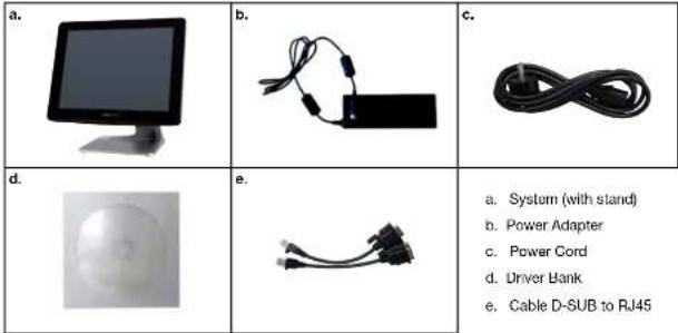
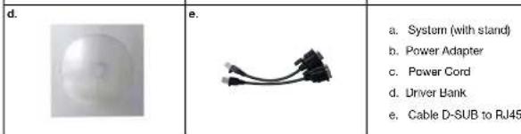
a. System (with stand)
b. Power Adapter
c. Power Cord
d. Driver Hank
e. Cable D-SUB to RJ45
1-2 Optional Accessories
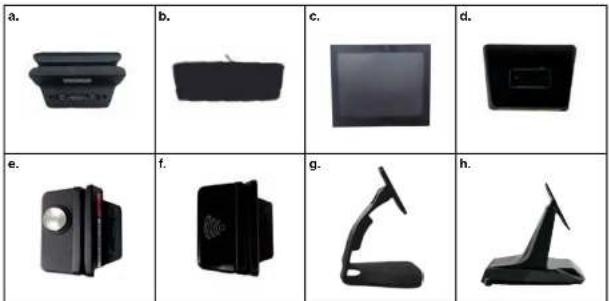
a. Single MSR e. MSR + iButton
b. 2x 20 VFD (pole or direct mount) f. MSR + RFID
c. 8" - 10" 2" Display, 15" 2" Display (pole) g. Stand option B
d. 1D or 2D Scanner h. Stand option C

www.coli.relics.info www.coli.net. comlc Colon relics P4100
Colon reticus P4100

2 SYSTEM VIEW
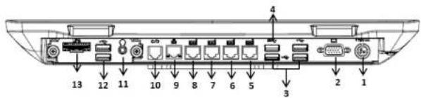
2-1 Rear View (I/O Type A)
2-2 Back View
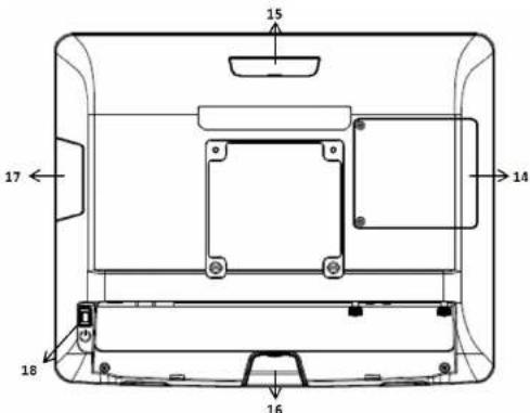
Item
1 19V DC Input 10 RJ11 (Cash Drawer)
2 VGA 11 Line Out x1
3 USB 2.0 x3 12 USB 2.0 x2
4 USB 3.0 x1 13 UPS Connector
5 RJ45 (COM4) 14 HDD Cover
6 RJ45 (COM3) 15 VFD Cover/8" 10" 2" Display (Option)
7 RJ45 (COM2) 16 1D/2D Barcode scanner (Option)
8 RJ45 (COM1) 17 MSR/i-Button/RFID (Option)
9 LAN port 18 Power Button
2-3 Specification
| Processor Intel® Celeron J1900 Quad Core 2.0GHz | ||
| Memory One SO-DIMM socket supports DDR3L up to 8GB | ||
| Storage 2.5" SATAI HDD / SSD | M.2 (22/2) 1x (SSD) | |
| Network RJ45 10/100/1000 Base-T | ||
| USB port 4x USB 2.0 / 1x USB 3.0 | ||
| Serial port 4x RJ45 (powered COM) | ||
| I/O option | Type A | 2x USB 2.0, UPS connector, 1x Line-out |
| Type B(P-CAP only) | 1x RS232 (RJ45 with DC 5W/12V selectable),UPS connector, 1x Line-out | |
| Type C | 2x USB 2.0, 1x 24V Powered USB , 1x Mic, 1x Line-out | |
| Type D | 1x Standard Parallel | |
| BIOS | Inside BIOS | |
| Power | AC 19V 60W Adaptor (Used for connecting all USB ports andone power COM port) | |
| AC 19V 90W Adaptor (STD) | ||
| AC 19V 150W Adaptor ( Use I/O type C) | ||
| Thermal Solution | Fanless | |
| Dimension | 374 (W) x 301 (F) x 37 (D) mm (w/o stand) | |
| Operating Temperature | 0°C ~ 35°C | |
| Storage Temperature | -20°C ~ 60°C | |
| Storage Humidity | 20% ~ 80%, non-condensing | |
| Display | ||
| LCD Panel Size | 15-inch TFT LED LCD | |
| Resolution | 1024*768 Pixels | |
| Brightness | 350 cd/m2 | |
| Touch Panel | 5-wire Resistive Type / Projected Capacitive Type | |
Note:
Intel® Celeron J1900 CPU does not support POSReady 2009


2-4 Internal Layout
M/B PCBA
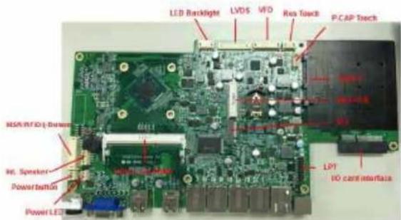
Type A I/O Card
2x USB
1x UPS
1x Audio
Type B I/O Card (PCAP and factory fixed unit)

1x RS232
1x UPS,
1x Audio
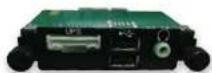
Type C I/O Card

2x USB
1x 24 V pUSB
1x Audio
Type D I/O Card
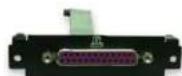
1x LPT
3 PIN DEFINITION
- LVDS Connector Pin Definition
| Pin NO. Definition Pin NO. Definition | ||
| 1NC 1 GND | ||
| 2 GND 12 Data 1 | ||
| 3 Data 3+ 13 Data 1- | ||
| 4 Data 3- 11 GND | ||
| 5 GND 15 Data 0 | ||
| 6 Clock- | 16 Data 0- | |
| / | Clock-1/ | NG |
| 8 GND 19 GND | ||
| 9 Data 2+ 19 | +3.3V | |
| 10 Data 2+ | 20 | -3.3V |
- LED Panel Backlight Pin Definition
| Ph NO. | Definition |
| 1 | +12V |
| 2 (GND) | |
| 3 | NC |
| 4 | Brightness |
| 5 | -50 Enable |
- SATA: 22-Pin SATA Pin Definition
| Pin NO. | Definition Pin NO. | Definition | ||
| S1 | CND | P1 | NC | |
| S2 | SATA IXOP | P2 | NC | |
| S3 | SATATXON | P3 | NC | |
| S4 | CND | P4 | CND | |
| S5 | SATATXON | P5 | CND | |
| S6 | SATATXOP | P6 | CND | |
| S7 | CND | P7 18V | ||
| P8 +5V | ||||
| P8 18V | ||||
| P10 | CND | |||
| P11 | CND | |||
| P12 | CND | |||
| P13 | NC | |||
| P14 | NC |
- Int. Speaker Pin Definition
| Pin NO. Definition |
| 1 Left Out + |
| 2 Left Out |
| 3 Right Out - |
| 4 Right Out + |
- Touch Panel Pin Definition
| Fin S.D. del kilo | |
| 1+5V | |
| 2 FxC | |
| 3 (×) | |
| 4 GND | |
- Printer Connector Pin Definition
| Pin NO. Definition Pin NO. Definition | |||
| 1 | STE# | 11 | PD4 |
| 2 | AH1# | 121+ | |
| 3 | PDC | 13 | PD5 |
| 4 | ENT# | 14 | SLCT |
| 5 PJ1 | 15 | FL6 | |
| 6 GINIT# | 16 | GND | |
| 7 PD2 | 17 PD7 | ||
| 8 | S IN# | 18 | GND |
| 9 | PD3 | 19 | ACK# |
| 10 | BUSY | 20 | GND |
- VFD Connector Pin Definition
| Pin NO. Delin for Pin NO. Detition | |||
| 1 RTS# 8 fSV | |||
| 2 CND7 | -5V | ||
| 3 x D9 | USB D> | ||
| 4 FxD | 9 | USB D | |
| 5 | CTS# | 10 | GND |
- MSR Connector Pin Definition
| Fm NO.1 Dein ion Fm NO.1 Definion | |||
| 1+5V7 | USD D+ | ||
| 2+5V8 | USD B | ||
| 3 | GND9 | USD D+ | |
| 4 | USD D- | 10 | GND |
| 5 | USD D+ | 11 | 13.3V |
| 6 | USD D- | 12 | +3.3V |
- LINE-OUT JACK Pin Definition
| Fin: NO.1 Delnillo | |
| 1 | GND AUD |
| 2 | GND AUD |
| 3 | INF OUTR2 |
| 4 | LINE OUTR2 |
| 5 | LNC2 JD |
- MIC-IN JACK Pin Definition
| Pin NO. | Definition |
| 1 | GND AUD |
| 2 | GND AUD |
| 3 | MIC1 N |
| 4 | MIC1 N |
| 5 | MIC1 JD |
- UPS Battery Connector Pin Definition
| Pin NO. | Definition Pin NO. Definition | ||
| 1 | GND 7 | HA ID | |
| 2 | GND 9 | Dat+ | |
| 3 | GND 9 | Dat+ | |
| 4 | GND | 10 | Hall+ |
| 5 | SMDDATA | 11 | Dat+ |
| 6 | SMKCI K |
- 24V USB Connector Pin Definition
| Pin NO.1 Definition Pin NO. Definition | |||
| 1-5V 5 | GND | ||
| 2 | USB10- | 8 | +24V |
| 3 | USB10+ | 7 | +24V |
| 4 | GND 8 | GND | |
4 REAR I/O INTERFACE
- RJ45 Powered COM (COM1, COM2, COM3, COM4) port
| Pin NO. Definition |
| 1 15V/ 12V |
| 2 DGR# |
| 3 GND |
| 4 DIF# |
| 5 RS# |
| 6 CIR# |
| 7 XJ |
| 8 RxQ |
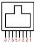
Pin 1: +5V / +12V
Pin 2: DSR#
Pin 3: GND
Pin 4: DTR#
Pin 5: RTS#
Pin 6: CTS#
Pin 7: TxD
Pin 8: RxD
NOTICE:
☆ COM1-4 port. Warning!! Never use on network device. If you are using on the network device will cause the device damaged.
☆☆ COM 4 port will be inactive if POS has internal VFD. (Alternative of COM 4 or internal VFD)
- RJ11 (Cash Drawer) Connector Pin Definition
| Pin NO: Signal Name Direction | ||
| 1 | Frame GND | - |
| 2 | Drawer Kick out drive signal1 | Output |
| 3 | Cash Drawer Status | input |
| 4 | +2V/+2V | - |
| 5 | NC | |
| 6 | Signal GND | - |
Example DOS COMMAND
for Cash Drawer
- Create the file: TEST.TXT
-
Input below contents in TEST.TXT CONTEXT-"000.0" MODE COM 6:300
-
DC JACK Pin Definition
| Pin NO. Definition | |
| 1 | +19V |
| 2 | Ground |
| 3 + 19V | |
5 SYSTEM ASSEMBLY & DISASSEMBLY
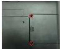
5-1 HDD
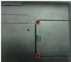
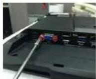
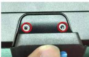
natural_image
Close-up of a metallic surface with two red circular markers highlighting specific points (no text or symbols present)- Unscrew 2 screws and remove the base cover
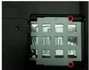
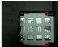
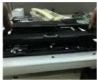
natural_image
Close-up of a computer monitor rear panel with multiple display cases and two red location markers (no visible text or symbols)- Unscrew 2 screws on HDD bracket
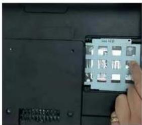
- Pull out the HDD bracket

natural_image
Close-up of a gray electronic device casing with multiple compartments and buttons, no visible text or symbols.- Fasten HDD on HDD bracket with 4 screws
5-2 Memory
1. Unscrew 2 screws and remove the base cover
2. Unscrew 2 screws on HDD bracket

3. Pull out the HDD bracket

4. Unscrew 2 screws I/O Board 5.
Unscrew 1 screw on VFD 6. Unscrew 1 screw on Barcode
7. Unscrew 2 screws on VGA
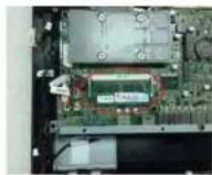
8. Remove the back cover 9. Put the memory into socket
5-3 MSR/i-Button/RFID

natural_image
Close-up of a finger pressing down on a dark fabric or panel (no visible text or symbols)- Remove MSR cover
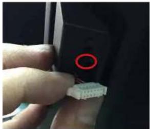
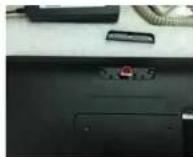
natural_image
Close-up of a finger pointing to a small white connector with a red circle highlighting the tip (no text or symbols visible)- Install MSR holder with 2 screws
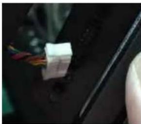
natural_image
Close-up of a hand holding a small white connector with wires, partially visible against a dark background (no text or symbols)- Plug MSR cable
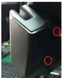
natural_image
Close-up of a black server tower with two red circular markers on its side (no visible text or symbols)- Install MSR with 2 screws
5-4 VFD/8" or 10" Display

natural_image
Close-up of a hand holding a rectangular object against a dark background (no visible text or symbols)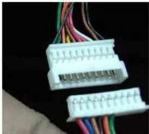
natural_image
Close-up of two white electrical connectors with multicolored wires against a black background (no visible text or symbols)- Remove the Top cover 2. Plug VFD cable / Plug 8" or 10" display cable
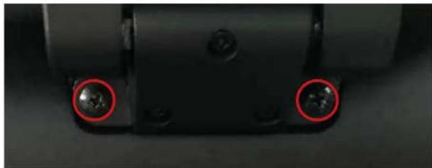
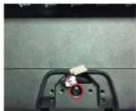
natural_image
Close-up of a mechanical component with two red-circled holes (no text or symbols visible)- Install VFD with 2 screws/Install 8" or 10" 2" display with 2 screws
☆ Alternative of external COM4 (RJ45 Connector) or Internal VFD.
5-4-2 15" 2nd Display
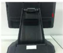
- Remove back cover of the stand
natural_image
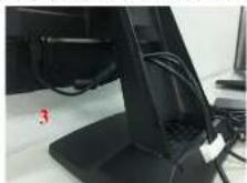
Close-up of a black electronic device with a handle and label, no visible text or symbols- Plug in DC 19V, VGA and the end of RJ45 of "RJ45 to D-SUB 9P" cables to the DC Jack, VGA and RJ45 ports on the system

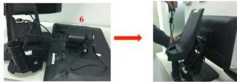
natural_image
Close-up of a computer monitor showing ports and cables, with a red arrow indicating transformation (no text or symbols visible)- Arrange the cables, as shown in the figure
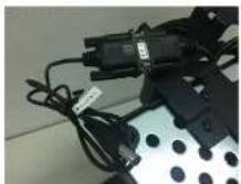
- Connect the end of D-SUB 9P female of the "D-SUB 9P to DC Jack" cable to the other end of D-SUB 9P male cable
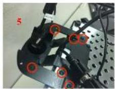
- Fasten the 6 screws on the extended base to the frame base
natural_image
Close-up of mechanical components with red circular markers, no visible text or symbols- Install the tube into the extended base and arrange the cables as shown in the figure then restore the back cover of the stand
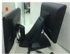
natural_image
Two-panel image showing a device with cables and a red arrow pointing to a monitor screen (no visible text or symbols)- Plug in the other end of VGA and DC Jack of the "D-SUB 9P to DC Jack" cables to the 15" 2nd display

- Install complete
Refer to P.66 using the power menu to enable the 12V power to the COM port is connected to the 15" 2nd display.
5-5 1D/2D Barcode Scanner

natural_image
Close-up of a finger pressing a black electronic component with a metallic clip (no visible text or symbols)- Remove the Barcode cover

natural_image
Close-up of a car's electrical connector with wires and connectors (no visible text or symbols)- Plug Barcode cable
natural_image
Close-up of a finger pressing a button on a mechanical component (no visible text or symbols)- Install Barcode with 2 screws
6 DEVICE DRIVER INSTALLATION
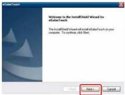
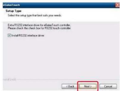
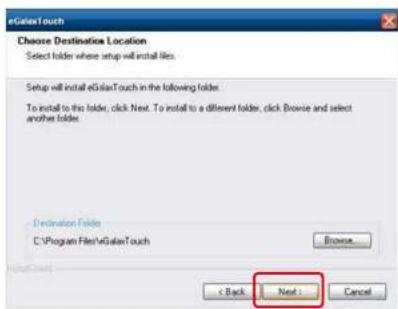
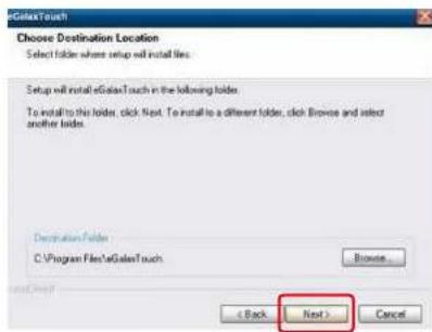
6-1 Resistive Type Touch Panel and P-CAP
- Click "Next".
- Click "Next".
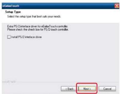
- Click "Next".
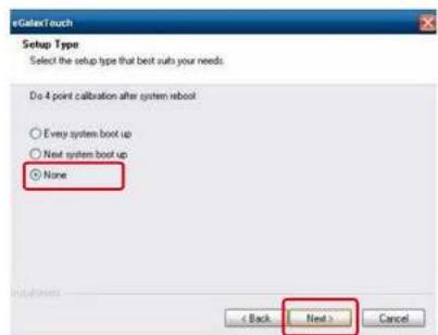
- Select "None", Click "Next".
- Click "OK".

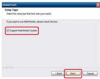
- Select "Support Multi-Monitor System", Click "Next".
- Click "Next".
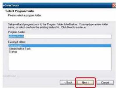
- Click "Next".
- Click "Next".
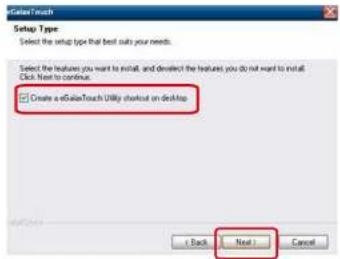
- Select "Create a eGalaxTouch Utility shortcut on desktop", Click "Next".
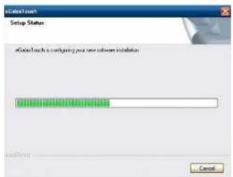
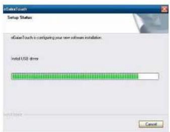
- Would you do 4 point calibration now? Click "Yes".

- Do 4 points alignment to match display.

natural_image
Blank white image with two small circular markers: one marked with a red plus sign and the other with a gray circle containing the number 14 (no text or symbols beyond these markers)- Calibration utility.

6-2 MagStripe Card Reader Configuration Utility
The MagSwipe Configuration Utility is used to set up the output format of MagSwipe.
Installation
Below steps guide you how to install the Utility program.
- Insert the setup CD.
- Run the 80066804-006 Magswipe Configuration Software V2 1 A setup file that is located in the Software folder of CD.
• Follow the wizard to complete the installation.
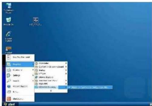
Launching Program
Below steps guide you how to load the Utility program.
- From Start/Programs, click MagSwipe folder.
- Click MagSwipe Configuration Utility to launch the program.
Configuration

Select Reader Interface
The reader to be configured should be connected. Select the corresponding connected reader interface and click the Continue button.

After the interface selection is made, click the Continue button. The utility attempts to communicate with the connected reader. If successful, the Home Menu Page is displayed. The Home Menu Page is shown below.
IDTECH
MagSwipe Configuration Utility
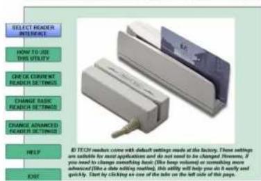
Change Basic Reader Setting
After selecting the appropriate interface for the reader, select one of the Home Menu Page buttons to proceed with the Magnetic Stripe Reader (MSR) configuration process. The "Basic Reader Settings" group defines the basic operating parameters and data output format of the reader.
IDTECH
MagSwipe Configuration Utility
Button Definitions
Send To MSR
When all the setting parameters are selected, use the "Send To MSR..." button to send configuration data to the reader device. When the reader has received the data correctly, the settings take effect immediately.
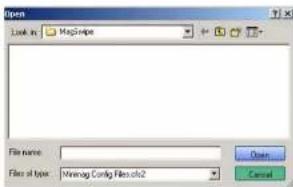
Load From File
The configuration data can be loaded into the configuration utility from a file that has been previously saved. Select this command, start a „File Open" dialog, which allows selection of the file.
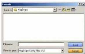
Save To File
The configuration data can be saved as a file and being used later to configure other readers. When saving a configuration the „File Save“ dialog is opened as shown below. Input a filename and file location.
Default All
This button sets the reader with the default configuration parameters (the default factory settings). The settings take effect immediately. The default parameters affect all reader configurations settings.
Close
Close this dialog and return to the Home Menu Page.
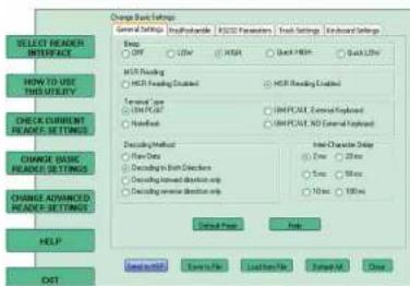
General Settings
This group of configuration settings defines the basic operating parameters of the reader.
IDTECH
MagSwipe Configuration Utility
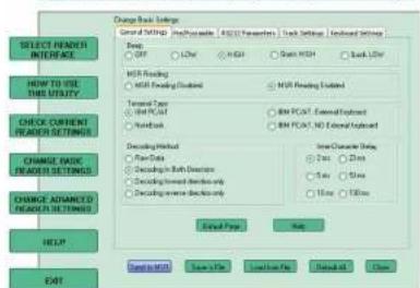
MSR Reading
This option will turn on or off the MSR. If MSR is disabled no data is sent out to host in any case. The default is MSR Reading Enabled.
Decoding Method Settings
This option gives four kinds of decoding methods
Raw Data (output in both forward and reverse directions)
Decoding in Both Directions (forward and reverse reading)
Decoding in Forward Direction only (card entering slot from LED end)
Decoding in Reverse Direction only (card entering slot from end opposite LED)
With the bi-directional operation, the user can swipe the card in both swipe directions and the data encoded on the magnetic stripe will be output. In the single swipe direction selections, the card can only be swiped in one specified direction to read the card. The default setting will decoding card data with the card swiped in either the forward or the reverse direction.
"Raw Data" is an output of the decoded magnetic stripe data in hexadecimal format (no ASCII character conversion is performed). In the Raw Data setting, the reader outputs all track-decoded data. The MSR will represent the raw data with two ASCII characters: the first ASCII character is for high bits of the raw data byte and the second is for the low bits. For example, the two ASCII characters, "A" and "I" represent raw data Byte 41h (01000001).
Beep Volume
The Beep volume can be adjusted to four loudness levels or off. Four loudness levels are:
Quick High
Quick Low
High
Low
The default is High beep
Terminal Type
NoteBook
IBM-PC/AT
IBM-PC/AT. External keyboard
IBM-PC/AT, No External keyboard
The firmware can be programmed to interface as a keyboard wedge to 4 different types of terminals.
The default is IBM-PC/AT.
Inter-Character Delay
2ms, 5ms, 10ms, 20ms, 50ms, 100ms;
This is the time period the reader will delay between sending successive characters. Some terminals or computers (host) require an inter-character delay to simulate the effects of keystroke delays. Choosing a longer inter-character delay causes the characters to be sent at a slower rate. If the host system is not capable of receiving characters as fast as the reader can transmit, setting an appropriate inter-character delay will keep the reader from overrunning the host input buffer. The default is 2ms.
Default Page Button
After you click the Default Button, the general settings page will change back to the default value. Settings are not sent to MSR until the „Send to MSR“ button is clicked.
Help Button
Click the help button to open the help index for this section.
Pre/Postamble
Preamble
Characters can be added to the beginning of the reader's output string of data. These can be special characters for identifying a specific reading station, to format a message header expected by the receiving host, or any other character string. Up to nine ASCII characters can be defined for the Premable.
Postamble
The Postamble serves the same purpose as the Preamble, except the extra characters are added to the end of a data string. The Postamble can be added only after a terminator character, if specified.
Track Prefix and Suffix
For some Host applications, it may be convenient to start or end a string of reader data with a Sentinel or terminator character. The maximum Prefix/Suffix string is six characters and its default is NULL (no prefix or suffix).
Track Start Sentinels
Characters can be added to the beginning of each track data string to simulate the start of the track data. These can be special characters for identifying a specific track.
End Sentinel
The magnetic stripe End Sentinel character can be added to the end of a magnetic stripe data string. This character simulates the end of character for track 1, track 2 or track 3. This default is ,?'.
Track Settings
IDTECH MagSwipe Configuration Utility
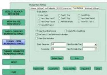
Track Selection
There are three tracks of information possible on a magnetic stripe. This option selects the tracks that will be decoded (read). Note that the magnetic stripe reader must have the hardware configuration (read head and circuits) for reading the specified tracks. If a single or dual track reader is used, the heads must be positioned to read the tracks selected by this option. The default is any track (All tracks written on the card will be read).
Track Separator Selection
This option allows the user to select the character to be used to separate data decoded by a multiple-track reader. The default value is CR.
Send Start/End Sentinel
The reader can send the Start/End sentinel for a track, decoded without error.
Send LRC in Card Data
The reader can send the track LRC for a properly decoded track.
For Track 2 only Send Account Number
The reader can only send account Number if it is true. And if it is false, the reader sends all track 2 data.
Send Error Indication
This option let reader to send out [SS]E[ES] if failed to read or missing data on a selected track. The default is off.
The error output for track 1 is „%E?“.
The error output for track 2 is „;E?“.
The error output for track 3 is „+E?“.
Keyboard Settings
IDTECH
MaySwipe Configuration Unity
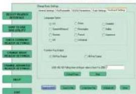
Keyboard Settings
There are keyboard settings information on a magnetic stripe. MiniMag II will support following foreign language keyboard and function key output for PS/2 and USB HID Keyboard Interface.
Language Option
This option allows the user to select the keyboard language of US, Swiss, Swedish, Norwegian, Italian, Spanish (Mexico). German, French, Japanese, UK and Universal. Universal language sends out all the data as a series of ALT keyed sequence.
Function Key Output
The function key output be used to support the special key to delay card data output.
USB HID KB Polling Interview
The user can input the number between 1 to 255 for the delay of output.
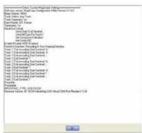
Check Current Reader Setting
After you connect the device, the current reader configuration can be displayed by selecting this button. The configuration data of the connected reader will be displayed like in the example:
6-3 RFID
1. Install driver
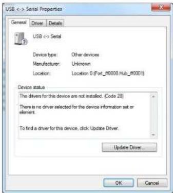
1.1 Check the Device Manager to verify the status of RFID reader.
Computer Management -> Device Manager -> Other devices (The device will show a question mark if the installation is not done properly.)
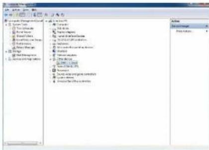
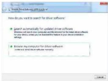
1.2 Double-click to Update driver.
1.3 Select "Browse my computer for driver software".
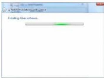
1.4 Click Browse to select file called HFF320U \Driver\FTDI\x64 and click Next.

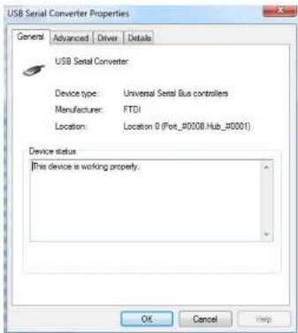
1.5 Install the driver.
1.6 Install complete and then click "close".
1.7 Restart the computer.
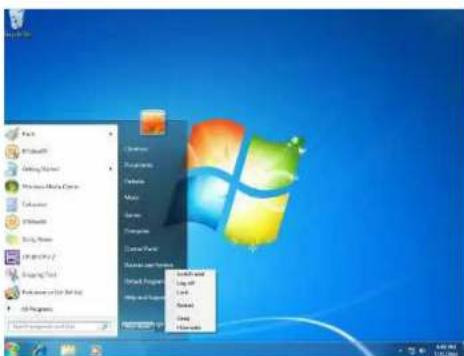
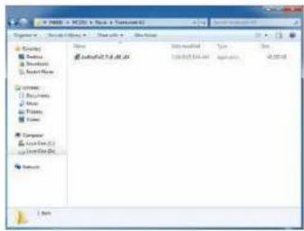
2. Install framework 4.0
2.1 Double-click to install.

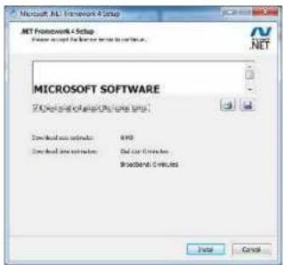
2.2 Select I have read and accept the license terms. And click install.
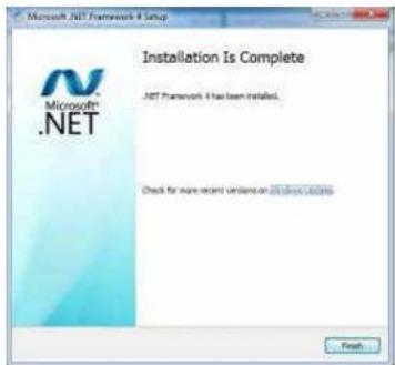
2.3 Click Finish.
3. Quick Start with Demonstration Software
3.1 The demonstration software is "MP Studio.exe" provided in the folder "Demo Software". There is no software setup required; just double click the "MP Studio.exe". The demonstration software can run either from CD or a copy on hard drive. The GUI of software is shown in below picture and ready to use.
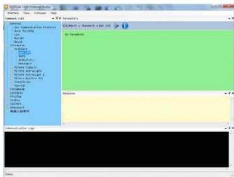
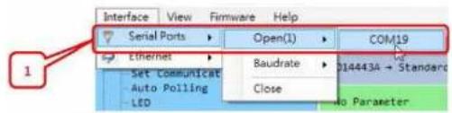
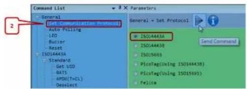
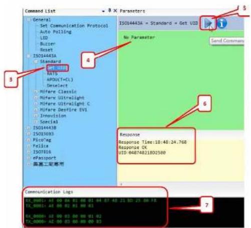
3.2 Following steps, as shown in below picture, demonstration a simple usage in reading UID of ISO14443A card for quick understanding.
6-4 USB 2nd Display
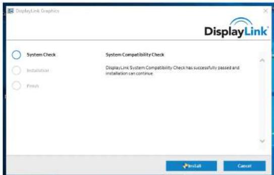
DisplayLink software can be installed from Windows Update. Alternatively, the software can be downloaded and installed from the DisplayLink website following the steps below.
- Double click on the DisplayLink executable, eg DisplayLink_RX.X.exe. The Windows User Account Control window opens (if enabled in the OS).
- Click Yes. DisplayLink Core Software Installs.

- The System Compatibility Check then runs.
- Click Install (if the System Compatibility Check passes).
- Connect your DisplayLink enabled device.
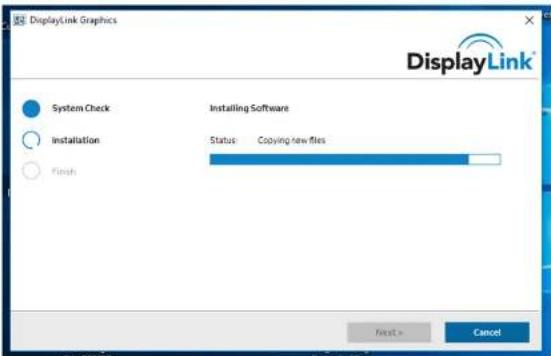
- Upon detection of a DisplayLink enabled device DisplayLink Graphics installs.
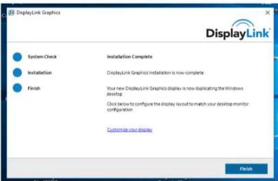
- You are then informed when installation of DisplayLink software has completed.
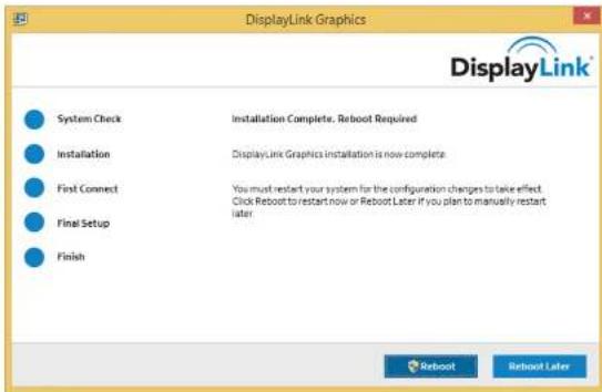
- Reboot your SYSTEM to complete the installation.
Due to the Intel BayTrail J1900 CPU limitation, the DisplayLink driver can only be supported extend mode.
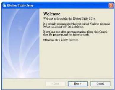
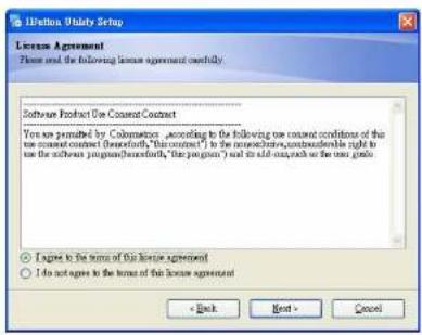
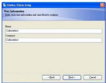
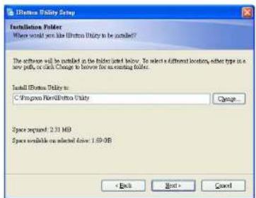
6-5 Configuration Utility of i-Button Reader
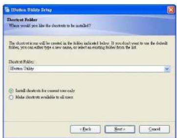
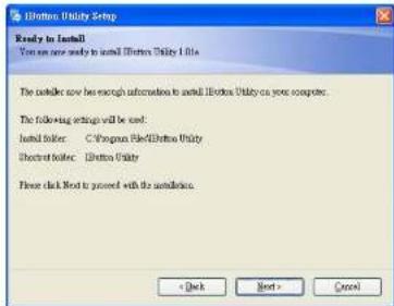
Installation
Below steps guide you how to install the Utility program.
- Insert the setup CD.
- Run the ColometricsButtonUtility.exe setup file that is located in the Software folder of CD.
-
Follow the wizard to complete the installation.
-
Setup IButton V1.0.exe software
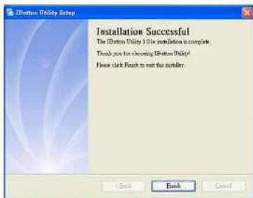
-
To execute "IButton_V1.0.exe" for setup communication between software and IButton module
-
The utility program will detect the connected reader. If detected, all the input text boxes will be enabled.
- If the reader has not been connected to PC yet, please connect the reader and then click Refresh to get connected.
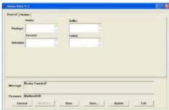
Configuration
Below is the main window of i-Button Utility program
For the settings, there are:
- Prefix/Suffix: Defines the data string which you would like to append in front or end of
the i-Button key string.
iButton Data Package :

- Error Message: Indicates error message when i-Button key read fail.
- Message: Indicates message when i-Button key read correctly.
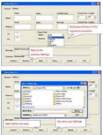
- SS/ES: Define Start and End sentinel byte for the i-Button ID string.
iButton data format:
Start Sentinel + iButton 64- Bit Registration Number + End Sentinel.
• Length : i-Button ID length request from 0-16.
- Output order: 4 formats could be select at Attach /Remove i-Button ID.
iButton 64- Bit Registration Number:
8-Bit CRC + 48-Bit ID + 8-Bit FC.
DEMO SETUP & OUTPUT
OUTPUT DATA :
a!ab00000003bdfa01?
b!ab00000003bdfa01?
6-6 VFD VD1220
-
Power on VFD and waiting test page of EEPROM test, Baud rate and Command page Set up the customer display by „VFDset.exe”
-
Setup VFDset.exe software
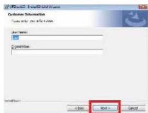
![Microsoft Select Desktop Wizard Installation folder This Next will be installed to the Web, or which Changes to be installed in a Web Server Folder. Select Desktop Wizard [ ] Windows (Windows NT) / [ ] Windows (Windows NT) / [ ] Windows (Windows NT) / [ ] Windows (Windows NT) / [ ] Windows (Windows NT) / [ ] Windows (Windows NT) / [ ] Windows (Windows NT) / [ ] Windows (Windows NT) / [ ] Windows (Windows NT) / [ ] Windows (Windows NT) / [ ] Windows (Windows NT) /[ ] Windows (Windows NT) / [ ] Windows (Windows NT) / [ ] Windows (Windows NT) / [ ] Windows (Windows NT) / [ ] Windows (Windows NT) / [ ] Windows (Windows NT) / [ ] Windows (Windows NT) / [ ] Windows (Windows NT) / [ ] Windows (Windows NT) / [ ] Windows (Windows NT) /\[ ] Next > Cancel](/content/2026/05/1058454/images/014d54d5d198b9f488fc12c714b36a25b75e77a80d4e9409922bcd12ce704ce7.jpg)
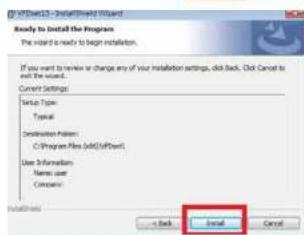
- To execute "VFDset.exe" for setting up communication between software and VFD module
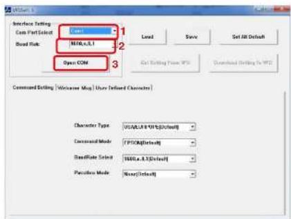
Please then follow the steps as shown in the above figure, the baud rate will show on states page of VFD module (Note: You may check it when power on VFD module), then click "Open COM" button.
-
"Get Setting from VFD" button to get all the settings and It'll refresh the "VFDset.exe" software
-
Select "Character Type"/ "Command Mode"/ "Baud Rate Select"/ "Pass-through Mode"
![Character Type USA/EURPOPE [Default] USA/EURPOPE [Default] Command Mode France Germany U.K. Denmark I Sweden BaudRate Select Command Mode EPSON [Default] EPSON [Default] BaudRate Select UTC/S UTC/P AEDEX BaudRate Select 9600,n,8,1 [Default] 9600,n,8,1 [Default] Passthru Mode 13200,n,8,1](/content/2026/05/1058454/images/0ce6abddd4fca6972c9a3051aa6467b72b8ccbd10a0c8bfd1adcaf373687bd03.jpg)
- Click "Set All Default" button To show default setting, the Default table is
Character Type : USA
Command Type : EPSON/EURPOPE
Baud Rate setting : 9600/n/8/1
Pass-through Mode: None
Welcome msg line 1: *** VFD DISPLAY ***
Welcome msg line 2: ** HAVE A NICE DAY AND THANK YOU **
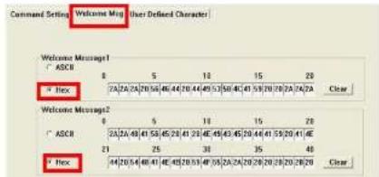
7. Welcome Message
Welcome Message line 1 maximum 20 characters, line 2 maximum 20 characters, total of 40 characters.
a. ASCII mode
You can type the character by keyboard (0x20h \~ 0x7Fh), if you press clear icon, it will clear the all Message characters on AP.
b. Hex mode
Hex mode can define the character from 0x20h to0xFFh the range 0x80\~0xFF which depends on the code page table.
![Command Session: Welcome Mag User Defined Character Welcome Message1 ASCII 0 5 10 15 20 * Hex [2A/2A/2A/20] (56/48/44/20) (49/53/58/4C/41) (53/20/28/2A/2A/2A Clear Welcome Message2 ASCII 0 5 10 15 20 * Hex [2A/2A/48/41/56/48/21] (29/48/49/43/45/20) (44/41/55/20/41) (4E * Hex [21/25/38/38/38/38/38/38/38/38/38/38/38/38/38/38/38/38/38/38/38/38/38/38/38/38/38/38/38/38/38/38/38/38/38/38](/content/2026/05/1058454/images/5bea002189b30fe9b465fb7e91579f1c42c6f6a4d06f7985026186f8c4d72913.jpg)
Like the first character (0x80) in default code page will show on VFD module.
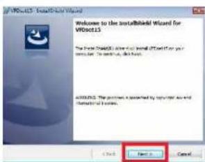
8. Click "Download setting to VFD" button
This button is to download the setting from VH-Set.exe to VH- module. After success dialog "Download O.K! Please restart!" message popped up. Please restart display for enable new setting.

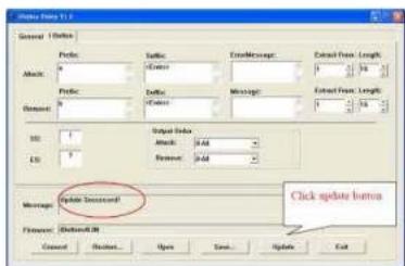
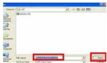
9. Click "Save" button
To save user's setting in file; for example, below picture to save file name as "GOODLUCK" file set for Welcome Message.
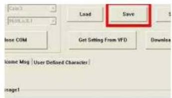
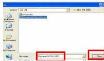
10. Click "Load" button
After saving, you must restart the utility here. Then load your setting rename-GOODLUCK.vfd.
![[com] [000000001] Load Save Set Close COM Get Setting From VFD Download S Income Mag | User Defined Character | message1](/content/2026/05/1058454/images/666ff6d14871109a2d6d28db89fb6f1bd8f798bb219c0080400f2e785e80d854.jpg)
7 BIOS/UTILITY SETUP
Press /
☆ Please press /
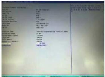
Press
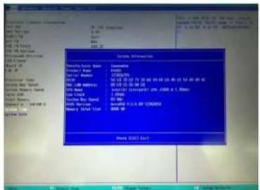
Date and Time
The Date and Time items show the current date and time on the computer. If you are running a Windows OS, these items are automatically updated whenever you make changes to the Windows Date and Time Properties utility.
WARNING!
Setting the wrong values in the sections below may cause the system to malfunction. Make sure that the settings made are compatible with the hardware.
7-1 Advanced
Use the Advanced menu to configure the system for basic operation through the following sub-menus:
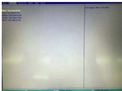
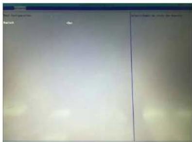
7-1-1 Boot Configuration
Use the Boot Configuration menu to select power-on state for Numlock.
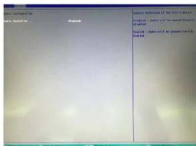
7-1-2 Audio Configuration
Use the Audio Configuration menu to read Audio configuration information and configure the Audio settings.
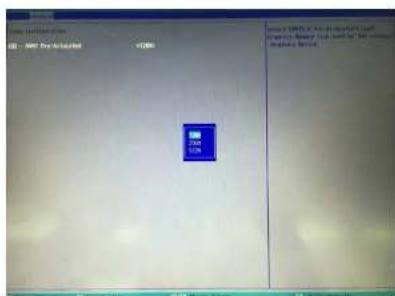
7-1-3 Video Configuration
Use the Video Configuration menu to read Video configuration information and configure the Video settings.
7-1-4 SATA Configuration
Use the SATA Configuration menu to read SATA configuration information and configure the SATA settings.
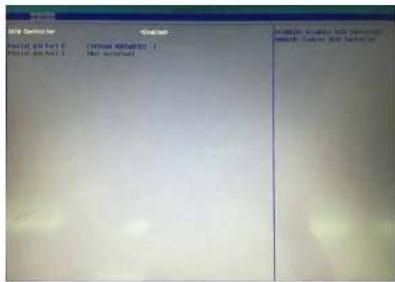
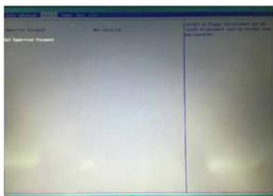
7-2 Security
Use the Security menu to install or change the password.
7-3 Power
Use the Power menu to install or change the password.
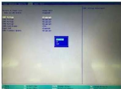
AC Loss Auto Restart
Enable or disable system power on automatically after AC power restored.
RTC Wake Up
When enabled, system will wake on the hr;;min;;sec specified.
Wake on LAN
Enable or disable system wake by onboard LAN chip.
Power button delay 4s
This item allows you to enable or disable power button delay 4s.
COM Voltage
This item allows you to select off, 5V or 12V powered COM.
LVDS Firmware update
This item allows you to enable or disable LVDS Firmware update.
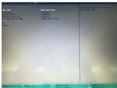
7-4 Boot
Use the Boot menu to select type to Dual type. Legacy type or UEFI type.
7-5 Exit
Use the Save & Exit menu to load default BIOS values, optimal failsafe values and to save configuration changes.
NOTICE
CE Notice
This device complies with the requirements of the CE directive.

WEEE Notice
This appliance is labeled in accordance with European Directive 2002/96/EC concerning waste electrical and electronic equipment (WEEE). The Directive determines the framework for the return and recycling of used appliances as applicable throughout the European Union. This label is applied to various products to indicate that the product is not to be thrown away, but rather reclaimed upon end of life per this Directive.
8 LCD SURFACE CLEANING
1. How to clean the LCD surface properly?
Do not spray any liquids on the LCD screen directly, and do not use paper towels, this can cause the LCD screen to become scratched.
☆ Always apply the solution to your cloth first, not directly to the parts you are cleaning. You want to avoid dripping the solution directly into your computer or laptop.
Stroke the cloth across the display in one direction, moving from the top of the display to the bottom.
2. What are some of the basic supplies needed to clean an LCD screen?
A soft cotton cloth. When cleaning the LCD screen it is important to use a soft cotton cloth, rather than an old rag. Some materials, such as paper towels, could cause scratches and damage the LCD screen.
Solution of water and isopropyl alcohol. This solution can be used along with the soft cotton cloth.
Computer wipes. Only use these if they specifically state on the package they are designed for LCD laptop screens. Computer wipes can come in handy for fast clean-ups or when you want to avoid mixing up a cleaning solution yourself.
3. What types of cleaners are acceptable?
Water
☆ Vinegar (mixed with water)
Isopropyl Alcohol
NOTICE: The following cleaners are unacceptable:
☆ Acetone
☆ Ethyl alcohol
Ethyl acid
☆ Ammonia
☆ Methyl chloride
- COPYRIGHT SAFETY INSTRUCTIONS
- Copyright 2015 Publishing. All Rights Reserved.
- Lithium Battery Caution:
- TABLE OF CONTENTS
- PACKING LIST
- SYSTEM VIEW
- Item
- Note:
- PIN DEFINITION
- REAR I/O INTERFACE
- NOTICE:
- SYSTEM ASSEMBLY & DISASSEMBLY
- 5-4-2 15" 2nd Display
- DEVICE DRIVER INSTALLATION
- 6-1 Resistive Type Touch Panel and P-CAP
- 6-2 MagStripe Card Reader Configuration Utility
- Installation
- Launching Program
- Configuration
- Select Reader Interface
- Change Basic Reader Setting
- Button Definitions
- Send To MSR
- Load From File
- Save To File
- Default All
- Close
- General Settings
- MSR Reading
- Decoding Method Settings
- Beep Volume
- Terminal Type
- Inter-Character Delay
- Default Page Button
- Help Button
- Pre/Postamble
- Preamble
- Postamble
- Track Prefix and Suffix
- Track Start Sentinels
- End Sentinel
- Track Settings
- Track Selection
- Track Separator Selection
- Send Start/End Sentinel
- Send LRC in Card Data
- For Track 2 only Send Account Number
- Send Error Indication
- Keyboard Settings
- Language Option
- Function Key Output
- USB HID KB Polling Interview
- Check Current Reader Setting
- 6-3 RFID
- Install driver
- Double-click to Update driver.
- Select "Browse my computer for driver software".
- Click Browse to select file called HFF320U \Driver\FTDI\x64 and click Next.
- Install the driver.
- Install complete and then click "close".
- Restart the computer.
- Install framework 4.0
- Quick Start with Demonstration Software
- 6-4 USB 2nd Display
- 6-5 Configuration Utility of i-Button Reader
- For the settings, there are:
- iButton data format:
- iButton 64- Bit Registration Number:
- OUTPUT DATA :
- 6-6 VFD VD1220
- Welcome Message
- Click "Download setting to VFD" button
- Click "Save" button
- Click "Load" button
- BIOS/UTILITY SETUP
- Date and Time
- WARNING!
- 7-1 Advanced
- 7-1-1 Boot Configuration
- 7-1-2 Audio Configuration
- 7-1-3 Video Configuration
- 7-1-4 SATA Configuration
- 7-2 Security
- 7-3 Power
- AC Loss Auto Restart
- RTC Wake Up
- Wake on LAN
- Power button delay 4s
- COM Voltage
- LVDS Firmware update
- 7-4 Boot
- 7-5 Exit
- NOTICE
- CE Notice
- WEEE Notice
- LCD SURFACE CLEANING
- How to clean the LCD surface properly?
- What are some of the basic supplies needed to clean an LCD screen?
- What types of cleaners are acceptable?
- NOTICE: The following cleaners are unacceptable:
Brand : Colormetrics
Model : P4100
Category : Cash register