E394S-IM-AA - Uncategorized ASUS - Free user manual and instructions
Find the device manual for free E394S-IM-AA ASUS in PDF.

User questions about E394S-IM-AA ASUS
0 question about this device. Answer the ones you know or ask your own.
Ask a new question about this device
Download the instructions for your Uncategorized in PDF format for free! Find your manual E394S-IM-AA - ASUS and take your electronic device back in hand. On this page are published all the documents necessary for the use of your device. E394S-IM-AA by ASUS.
USER MANUAL E394S-IM-AA ASUS
No part of this manual, including the products and software described in it, may be reproduced, transmitted, transcribed, stored in a retrieval system, or translated into any language in any form or by any means, except documentation kept by the purchaser for backup purposes, without the express written permission of ASUSTeK COMPUTER INC. ("ASUS").
ASUS PROVIDES THIS MANUAL "AS IS" WITHOUT WARRANTY OF ANY KIND, EITHER EXPRESS OR IMPLIED, INCLUDING BUT NOT LIMITED TO THE IMPLIED WARRANTIES OR CONDITIONS OF MERCHANTABILITY OR FITNESS FOR A PARTICULAR PURPOSE. IN NO EVENT SHALL ASUS, ITS DIRECTORS, OFFICERS, EMPLOYEES OR AGENTS BE LIABLE FOR ANY INDIRECT, SPECIAL, INCIDENTAL, OR CONSEQUENTIAL DAMAGES (INCLUDING DAMAGES FOR LOSS OF PROFITS, LOSS OF BUSINESS, LOSS OF USE OR DATA, INTERRUPTION OF BUSINESS AND THE LIKE), EVEN IF ASUS HAS BEEN ADVISED OF THE POSSIBILITY OF SUCH DAMAGES ARISING FROM ANY DEFECT OR ERROR IN THIS MANUAL OR PRODUCT.
Products and corporate names appearing in this manual may or may not be registered trademarks or copyrights of their respective companies, and are used only for identification or explanation and to the owners' benefit, without intent to infringe.
SPECIFICATIONS AND INFORMATION CONTAINED IN THIS MANUAL ARE FURNISHED FOR INFORMATIONAL USE ONLY, AND ARE SUBJECT TO CHANGE AT ANY TIME WITHOUT NOTICE, AND SHOULD NOT BE CONSTRUED AS A COMMITMENT BY ASUS. ASUS ASSUMES NO RESPONSIBILITY OR LIABILITY FOR ANY ERRORS OR INACCURACIES THAT MAY APPEAR IN THIS MANUAL, INCLUDING THE PRODUCTS AND SOFTWARE DESCRIBED IN IT.
Copyright © 2022 ASUSTeK COMPUTER INC. All Rights Reserved.
LIMITATION OF LIABILITY
Circumstances may arise where because of a default on ASUS' part or other liability, you are entitled to recover damages from ASUS. In each such instance, regardless of the basis on which you are entitled to claim damages from ASUS, ASUS is liable for no more than damages for bodily injury (including death) and damage to real property and tangible personal property; or any other actual and direct damages resulted from omission or failure of performing legal duties under this Warranty Statement, up to the listed contract price of each product.
ASUS will only be responsible for or indemnify you for loss, damages or claims based in contract, tort or infringement under this Warranty Statement.
This limit also applies to ASUS' suppliers and its reseller. It is the maximum for which ASUS, its suppliers, and your reseller are collectively responsible.
UNDER NO CIRCUMSTANCES IS ASUS LIABLE FOR ANY OF THE FOLLOWING: (1) THIRD-PARTY CLAIMS AGAINST YOU FOR DAMAGES; (2) LOSS OF, OR DAMAGE TO, YOUR RECORDS OR DATA; OR (3) SPECIAL, INCIDENTAL, OR INDIRECT DAMAGES OR FOR ANY ECONOMIC CONSEQUENTIAL DAMAGES (INCLUDING LOST PROFITS OR SAVINGS), EVEN IF ASUS, ITS SUPPLIERS OR YOUR RESELLER IS INFORMED OF THEIR POSSIBILITY.
SERVICE AND SUPPORT
Visit our multi-language web site at https://www.asus.com/support/
Contents
About this manual....5
Conventions used in this manual....6
Typography....6
Package contents ....7
Chapter 1: Specifications Summary
E395S / E394S / E393S-IM-AA R3.0
Specifications Summary....10
Chapter 2: Product Introduction
2.1 Before you proceed....14
2.2 Motherboard layout....15
2.3 System memory....17
2.4 Onboard jumpers....18
2.5 Internal connectors....22
2.6 I/O connectors....38
Chapter 3: Upgrading your Single Board Computer
3.1 Installing memory modules....40
3.2 Installing 2.5" storage device ....41
3.3 Installing the Mini PCIe card....42
3.4 Installing a Nano SIM card....43
3.5 Installing an Micro SD card....44
3.6 Installing the wireless card 45
3.7 Installing an M.2 SSD....46
3.8 Installing a heatsink....47
3.9 Installing a heat spreader....49
Chapter 4: BIOS Setup
4.1 Getting to know your BIOS....54
4.2 BIOS setup program....55
4.3 Main Menu....57
4.3.1 System Date [Day xx/xx/xxxx].... 57
4.3.2 System Time [xx:xx:xx]....57
4.4 Advanced menu ....58
4.4.1 Trusted Computing 59
4.4.2 PCH Storage Configuration 61
4.4.3 Onboard Devices Configuration....63
4.4.4 ACPI Settings 65
4.4.5 APM Configuration....66
4.4.6 SMART Settings....67
4.4.7 NCT6116D Super IO Configuration 67
4.4.8 NCT6116D HW Monitor 69
4.4.9 Serial Port Console Redirection....69
4.4.10 CPU Configuration....73
4.4.11 AMI Graphic Output Protocol Policy 77
4.4.12 PCI Subsystem Settings 77
4.4.13 USB Configuration 78
4.4.14 Network Stack Configuration 80
4.4.15 SDIO Configuration 81
4.4.16 Platform Trust Technology 81
4.4.17 Security Configuration 82
4.4.18 LFP Configuration 82
4.4.19 Thermal....83
4.5 Security 85
4.6 Boot menu....88
4.7 Save & Exit menu....92
4.8 Updating your BIOS....93
4.8.1 ASUS CrashFree BIOS 3 utility 93
4.8.2 ASUS EzFlash Utility....94
4.8.3 BUPDATER utility 96
Appendix
Safety information....100
Setting up your system....100
Care during use....101
Safety precautions....102
Regulatory notices....103
Service and Support....107
About this manual
This manual provides information about the hardware and software features of your Single Board Computer, organized through the following chapters:
Chapter 1: Specifications Summary
This chapter details the hardware and software features of your Single Board Computer.
Chapter 2: Product Introduction
This chapter describes the features of the motherboard. It includes description of the connectors, and I/O ports on the motherboard.
Chapter 3: Upgrading your Single Board Computer
This chapter provides you with information on how to upgrade the memory modules, wireless modules, and hard disk drive / solid state drive of your Single Board Computer.
Chapter 4: BIOS Setup
This chapter tells how to change system settings through the BIOS Setup menus. Detailed descriptions of the BIOS parameters are also provided.
Appendix
This section includes notices and safety statements your Single Board Computer.
Conventions used in this manual
To highlight key information in this manual, some text are presented as follows:
IMPORTANT! This message contains vital information that must be followed to complete a task.
NOTE: This message contains additional information and tips that can help complete tasks.
WARNING! This message contains important information that must be followed to keep you safe while performing certain tasks and prevent damage to your Single Board Computer's data and components.
Typography
Bold text Indicates a menu or an item to select.
Italic
This indicates sections that you can refer to in this manual.
Package contents
Your Single Board Computer package contains the following items:
natural_image
Floor plan layout with room layouts and equipment (no text or labels)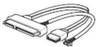
natural_image
Illustration of a USB cable with two connectors (no text or symbols)E395S-IM-AA / E394S-IM-AA / E393S-IM-AA R3.0 SATA and power cable
NOTE:
- Some bundled accessories may vary with different models. For details on these accessories, refer to their respective user manuals.
- The device illustration is for reference only. Actual product specifications may vary with models.
- If the device or its components fail or malfunction during normal and proper use within the warranty period, bring the warranty card to the ASUS Service Center for replacement of the defective components.
1
Specifications Summary
E395S / E394S / E393S-IM-AA R3.0 Specifications Summary
| E395S-IM-AA R3.0 | E394S-IM-AA R3.0 | E393S-IM-AA R3.0 | ||
| Form factor | 3.5", 146 x 105 mm | |||
| Processor | CPU | Intel® Apollo Lake-I, x7-E3950 | Intel® Apollo Lake-I, x5-E3940 | Intel® Apollo Lake-I, x5-E3930 |
| Max. Speed | 1.6GHz Quad-core (Turbo 2.0GHz) | 1.6GHz Quad-core (Turbo 1.8GHz) | 1.3GHz Dual-core (Turbo 1.8GHz) | |
| L2 Cache | 2MB | |||
| Chipset | Integrated | |||
| Memory | 1 x 204-pin SO-DIMM, max. 8GB, DDR3L 1866MHz, non-ECC, un-buffered memory | |||
| Storage | SATA port 1 x SATA 6GB/s connector (Gen 3.0) | |||
| Graphics | Controller | Intel® HD Graphics 505 | Intel® HD Graphics 500 | Intel® HD Graphics 500 |
| HDMI | 1 x HDMI supports HDMI 1.4b up to 3840 x 2160 @ 30 Hz | |||
| DisplayPort | 1 x DisplayPort supports DP 1.2 up to 4096 x 2160 @ 60 Hz | |||
| LVDS | 1 x LVDS supports 1920 x 1080 @ 60 Hz resolution in dual LVDS bus mode | |||
| eDP (optional) | 1 x eDP supports eDP 1.3 x4 lanes, Up to 3840 x 2160 @ 60 Hz | |||
| Multi Display | DP+HDMI+LVDS Multi-Display output: DP/HDMI/LVDS ports Supports up to 3 displays simultaneous under OS | |||
| Expan-sion slot | Mini PCIe | 1 x Full-Length Mini PCIe slot 1 x On-board Nano-SIM socket | ||
| M.2 | 1 x M.2 Socket 1 with E key, type 2230 for WIFI/BT device 1 x M.2 Socket 3 with M key, type 2242 (SATA mode) | |||
| Others | 1 x Micro SD Card slot (on-board) | |||
| Ethernet | 2 x Intel® I210IT, RJ-45 LAN ports, supports 10/100/1000Mbps | |||
(continued on the next page)
| Audio | Realtek ALC897/ALC887 High Definition Audio CODEC* The audio codec may vary between motherboards, please consult your sales window for the motherboard's exact codec type. |
| Rear I/O | 1 x DisplayPort1 x HDMI port4 x USB 3.2 Gen 1 Type-A ports2 x RJ-45 LAN ports |
| Internal connectors | 6 x Serial ports (2 x RS-232/422/485, 4 x RS-232)1 x USB 2.0 connector (supports additional 2 USB 2.0 ports)1 x 4-pin Chassis fan connector1 x Chassis intrusion connector1 x Front panel audio connector (AAFP)1 x System panel connector1 x Clear CMOS jumper1 x SATA power connector1 x LPC debug connector1 x SMBus connector1 x I2C connector1 x 4-pin Power connector1 x GPIO connector (8-bit) |
| Watchdog Timer (H/W) | Yes |
| Security | 1 x SPI TPM connector |
| Power Supply | DC 12-24V |
| Operating System | Windows® 10 (64bit)Win10 lot EnterpriseUbuntuRedHat EnterpriseFedora Workstation |
| Environment | Operating Temperature: -40°C ~ 85°CNon-operating Temperature: -40°C ~ 85°C |
NOTE: Specifications are subject to change without notice.
Product Introduction
2
2.1 Before you proceed
Take note of the following precautions before you install motherboard components or change any motherboard settings.
NOTE: The diagrams in this chapter are for reference only. The motherboard layout may vary with models.
IMPORTANT! Components shown in this section may require additional purchase. Refer to Package contents section for more information about the contents of your Single Board Computer package.
WARNING!
- Unplug the power cord from the wall socket before touching any component.
- Before handling components, use a grounded wrist strap or touch a safely grounded object or a metal object, such as the power supply case, to avoid damaging them due to static electricity.
- Hold components by the edges to avoid touching the ICs on them.
- Whenever you uninstall any component, place it on a grounded antistatic pad or in the bag that came with the component.
- Before you install or remove any component, ensure that the ATX power supply is switched off or the power cord is detached from the power supply. Failure to do so may cause severe damage to the motherboard, peripherals, or components.
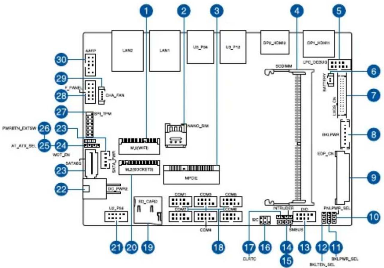
2.2 Motherboard layout
flowchart
graph TD
    A["30"] --> B["ANFP"]
    C["29"] --> D["F_PANEL"]
    E["28"] --> F["CHA_FAN"]
    G["27"] --> H["SPL_TPM"]
    I["PWRBTN_EXTSW"] --> J["26"]
    K["AT_ATX_SEL"] --> L["25"]
    M["WDT_EN"] --> N["SATAEG"]
    O["24"] --> P["DATA_PWR"]
    Q["23"] --> R["SD_CARD"]
    S["22"] --> T["DC_PWR2"]
    U["21"] --> V["US_P56"]
    W["20"] --> X["SD_CARD"]
    Y["19"] --> Z["COM1"]
    Y --> AA["COM2"]
    Y --> AB["COM3"]
    Y --> AC["COM4"]
    Y --> AD["COM5"]
    Y --> AE["COM6"]
    Y --> AF["COM7"]
    Y --> AG["COM8"]
    Y --> AH["COM9"]
    Y --> AI["INTRUDER"]
    Y --> AJ["SMRUS"]
    Y --> AK["DC"]
    AL["1"] --> AM["LAN2"]
    AN["2"] --> AO["LAN1"]
    AP["3"] --> AQ["U3_P54"]
    AR["4"] --> AS["U3_P72"]
    AT["5"] --> AU["DP3_HDM3"]
    AV["6"] --> AW["LPC_DEBUG"]
    AX["7"] --> AY["BATTERY"]
    AZ["RIO_PWR"] --> BA["LIVOS_ON"]
    BB["8"] --> BC["RIO_PWR"]
    BD["9"] --> BE["EDP_ON"]
    BF["PMLPWR_SEL"] --> BG["DRLPWR_SEL"]
    BH["10"] --> BI["DRLPWR_SEL"]
| Layout contents Page | |
| 1. M.2 Wi-Fi slot 24 | |
| 2. Nano SIM Card slot 24 | |
| 3. Mini PCIe slot 23 | |
| 4. DIMM slot 17 | |
| 5. Low Pin Count connector 27 | |
| 6. Battery connector 27 | |
| 7. LVDS connector (on selected models) 26 | |
| 8. Back Light Inverter Power connector 26 | |
| 9. EDP Signal connector (on selected models) 28 | |
| 10. LVDS Panel Power Selection jumper (on selected models) 19 | |
| 11. Back Light Power Selection jumper 19 | |
| 12. Back Light Power Enable jumper | 20 |
| 13. GPIO connector | 29 |
| 14. Chassis Intrusion connector | 33 |
| 15. System Management Bus connector | 29 |
| 16. I2C connector | 30 |
| 17. Clear RTC RAM jumper | 18/ |
| 18. Serial Port connector | 31 |
| 19. Micro SD card slot 23 | |
| 20. M.2 slot | 25 |
| 21. USB 2.0 connector | 32 |
| 22. DC-in 4-Pin Power connector | 37 |
| 23. SATA 6Gb/s & SATA Power connector | 22 |
| 24. HW WDT Enable jumper | 20 |
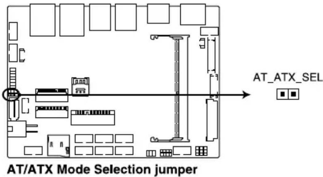
| 25. AT/ATX Mode Configuration jumper | 21 |
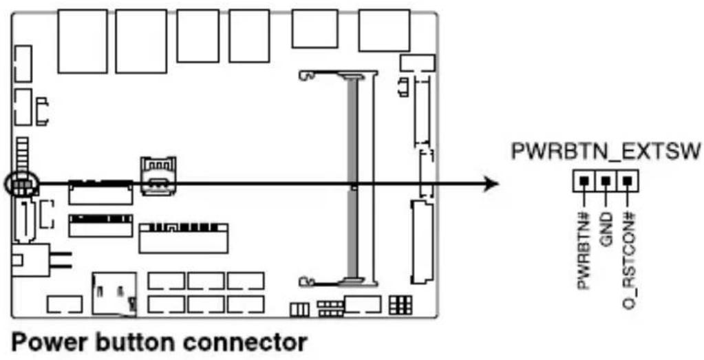
| 26. Power button connector | 25 |
| 27. SPI TPM connector | 30 |
| 28. System Panel connector | 35 |
| 29. Fan connector | 34 |
| 30. Line Out / Mic connector | 36 |
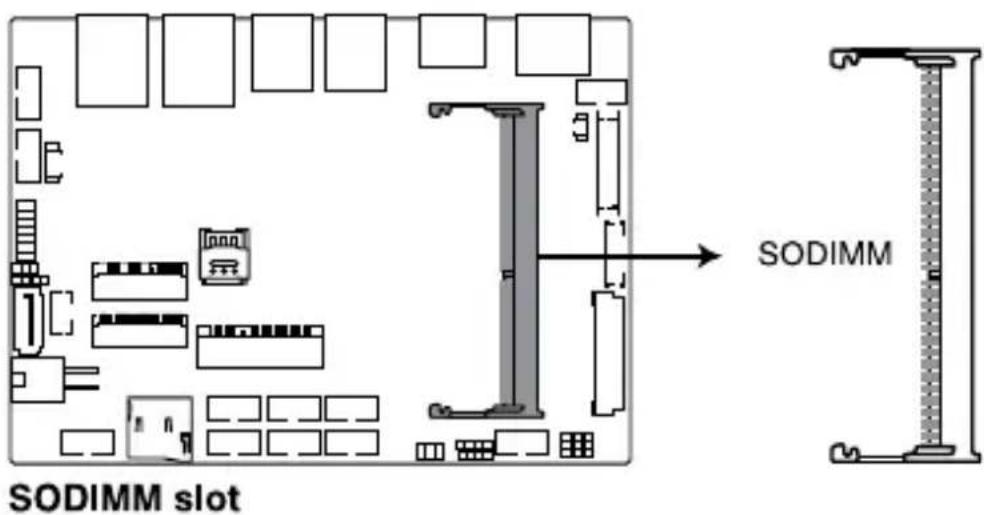
2.3 System memory
The motherboard comes with a Small Outline Dual Inline Memory Module (SODIMM) slot designed for DDR3L memory modules.
2.4 Onboard jumpers
1. Clear RTC RAM jumper
The Clear RTC RAM jumper allows you to clear the Real Time Clock (RTC) RAM in the CMOS, which contains the date, time, system passwords, and system setup parameters.
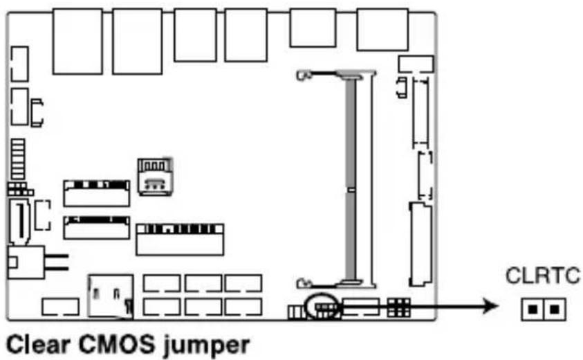
To erase the RTC RAM:
- Turn OFF the computer and unplug the power cord.
- Short-circuit pin 1-2 with a metal object or jumper cap for about 5-10 seconds.
- Plug the power cord and turn ON the computer.
- Hold down the
key during the boot process and enter BIOS setup to re-enter data.
WARNING! DO NOT remove the jumper cap from its default position except when clearing the RTC RAM. Removing the jumper cap will cause system boot failure!
NOTE: If the steps above do not help, remove the onboard button cell battery and move the jumper again to clear the CMOS RTC RAM data. After clearing the CMOS, reinstall the button cell battery.
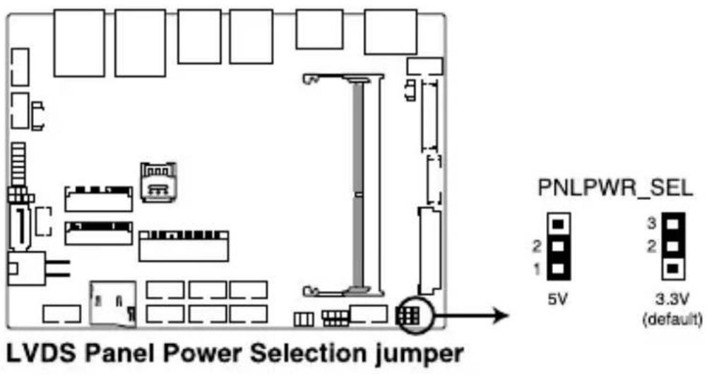
2. LVDS Panel Power Selection jumper (on selected models)
The LVDS Panel Power jumper allows you to select the voltage for the LVDS panel.
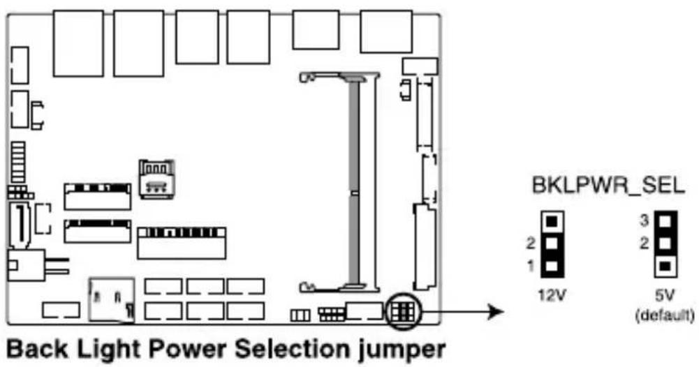
3. Back Light Power Selection jumper
The Back Light Power Selection jumper allow you to select the voltage for the LVDS back light module.
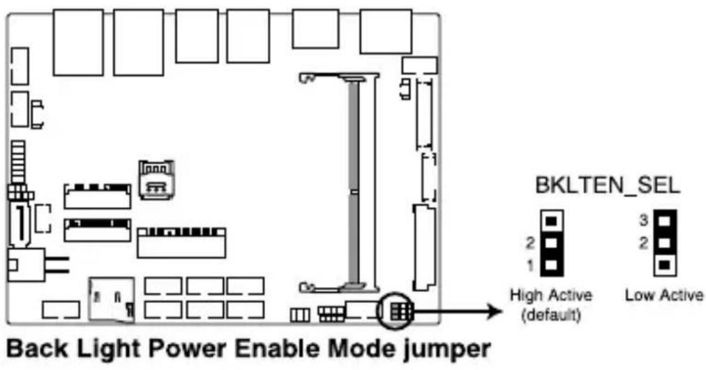
4. Back Light Power Enable jumper
The Back Light Power Enable jumper allows you to configure the power setting for the panel.
5. HW WDT Enable jumper
A watchdog timer is an electronic timer that is used to detect and recover from computer malfunctions. The HW WDT (watchdog timer) Enable jumper allows the HW watchdog resets the system automatically even when the system crashes.
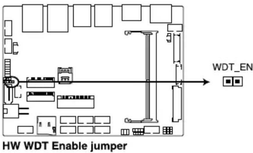
NOTE: The default setting for this jumper is set to HW WDT enabled with a jumper cap attached.
6. AT/ATX Mode Configuration jumper
The AT/ATX Mode Configuration jumper allows you to switch between AT or ATX modes. The default setting for this jumper is set to ATX mode with a jumper cap attached, to switch to AT mode, remove the jumper cap.
2.5 Internal connectors
1. SATA 6Gb/s & SATA Power connector
The SATA 6Gb/s and SATA Power connectors allow you to connect SATA devices such as optical disc drives and hard disk drives via a SATA cable and power cable.
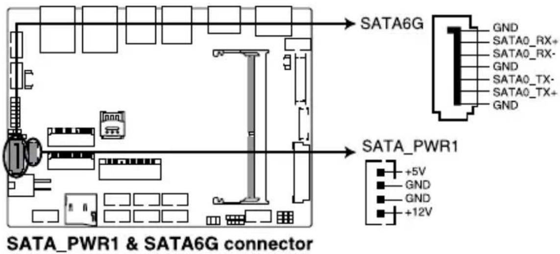
Connector type
Wafer HD 4P, 2.0mm pitch
NOTE: Ensure to use the bundled cable when connecting a storage device to this connector.
2. Mini PCIe slot
The Mini PCIe slot allows you to install a Mini PCIe peripheral device.
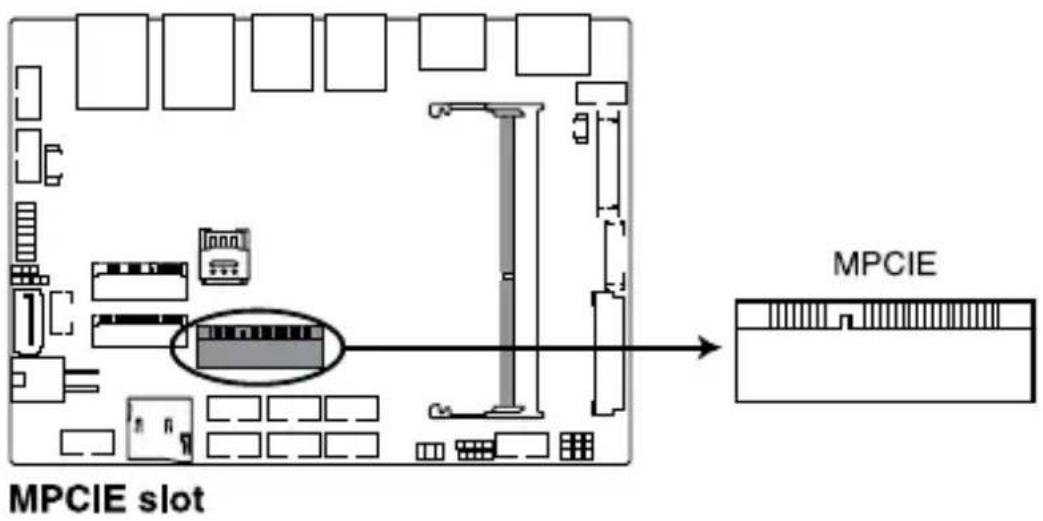
NOTE: The Mini PCIe peripheral device is purchased separately.
3. Micro SD Card slot
The Micro SD Card slot allows you to install a Micro SD card.
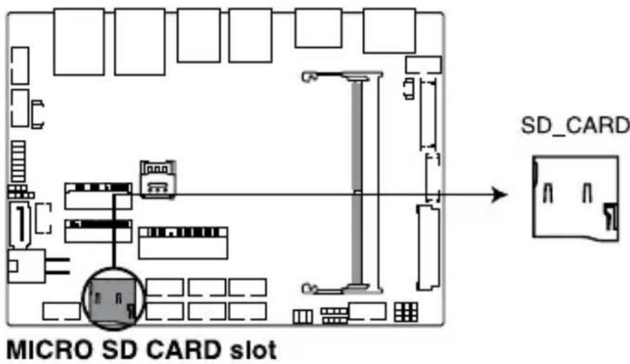
NOTE: The Micro SD card is purchased separately.
4. Nano SIM Card slot
The Nano SIM Card slot allows you to install a Nano SIM card.
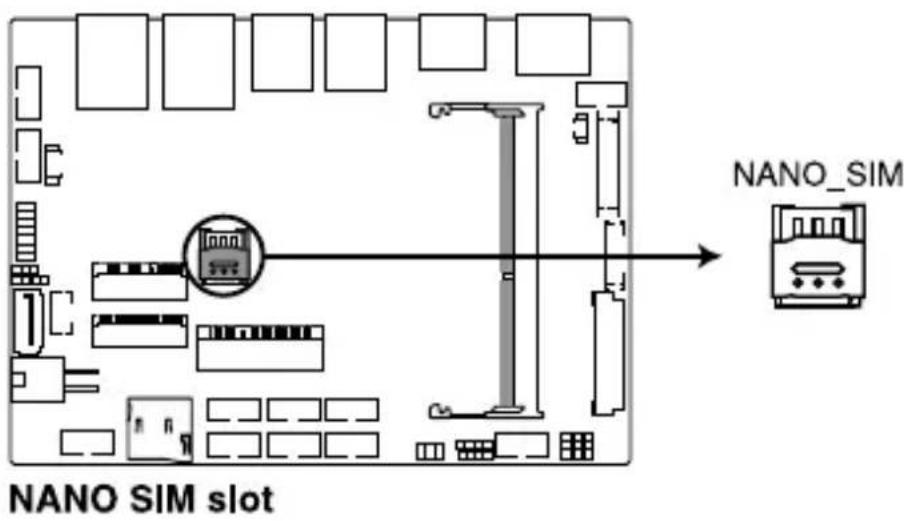
NOTE: The Nano SIM card is purchased separately.
5. M.2 Wi-Fi slot
The M.2 Wi-Fi slot allows you to install an M.2 Wi-Fi module (E-key, type 2230).
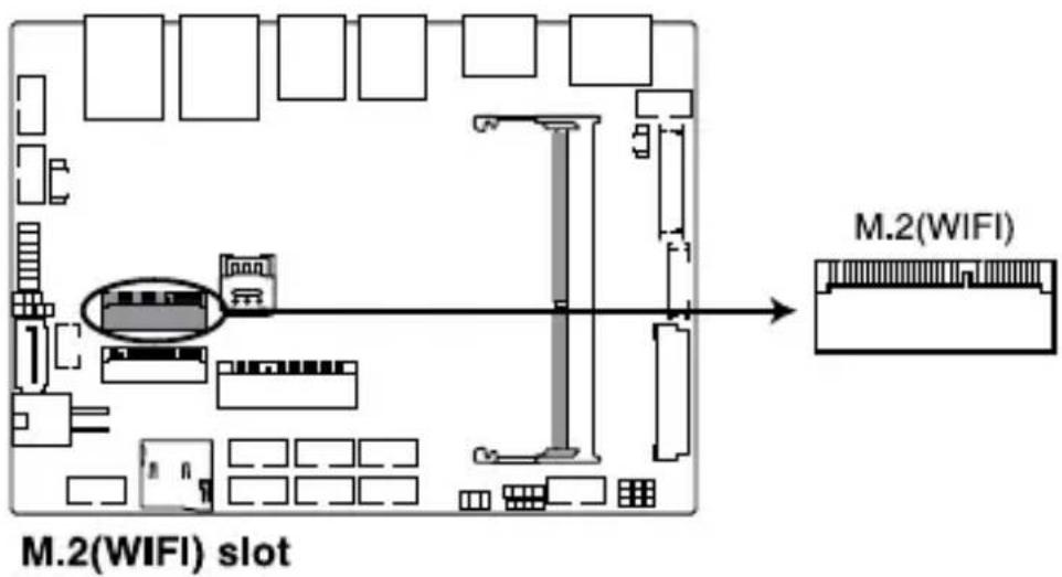
NOTE: The M.2 Wi-Fi module is purchased separately.
6. M.2 slot
The M.2 slot allows you to install 2242 M.2 devices such as 2242 M.2 SSD modules.
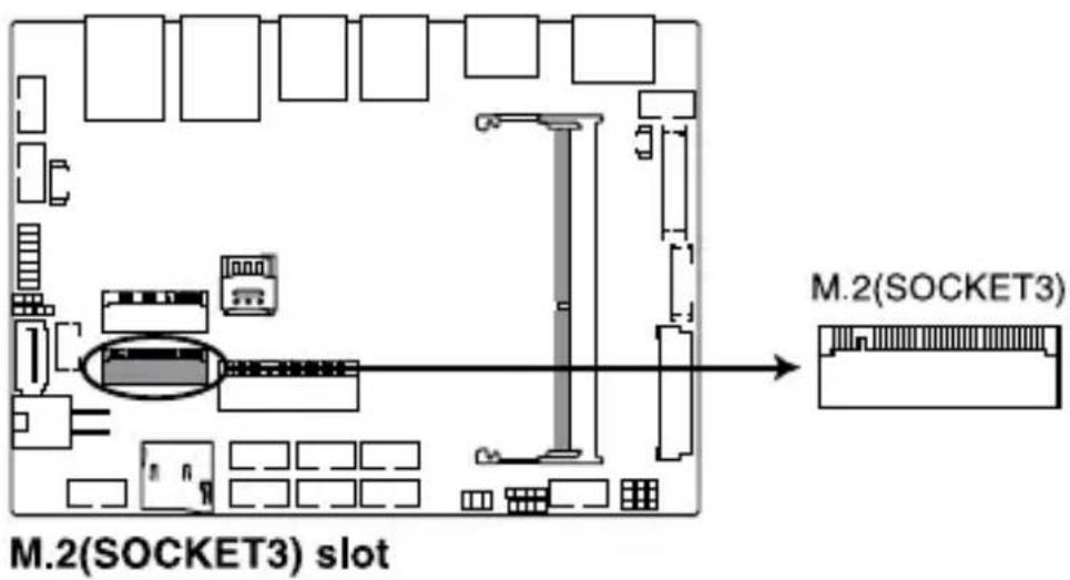
NOTE: The M.2 SSD module is purchased separately.
7. Power button connector
The Power Button connector allows you to connect an external power button.
8. LVDS connector (on selected models)
The LVDS connector allows you to connect a LCD monitor that supports a Low-voltage Differential Signaling (LVDS) interface.
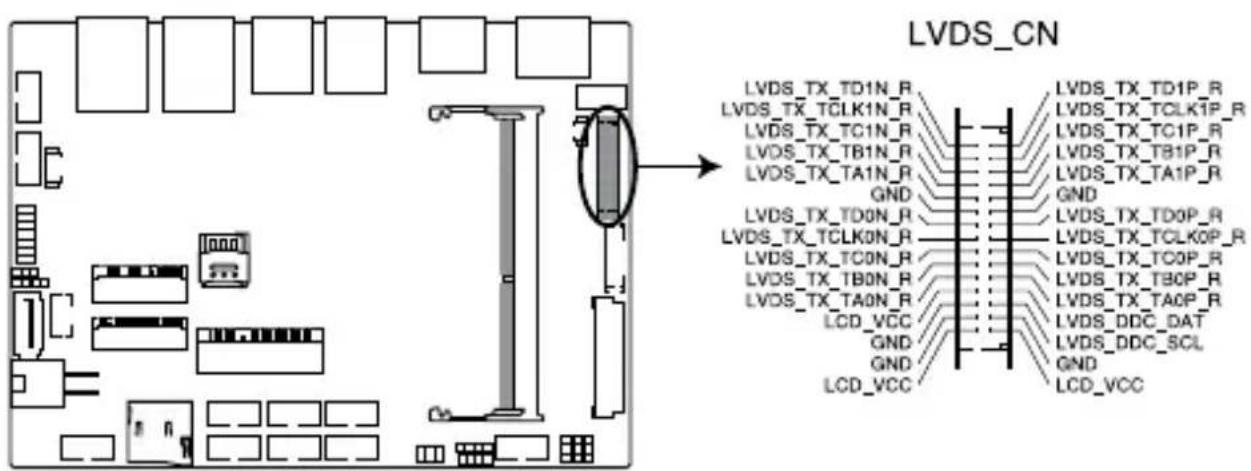
LVDS connector
Connector type
WAFER HD 2X15P 1.25MM pitch
9. Back Light Inverter Power connector
The Back Light Inverter Power connector is for the panel back light module power input.
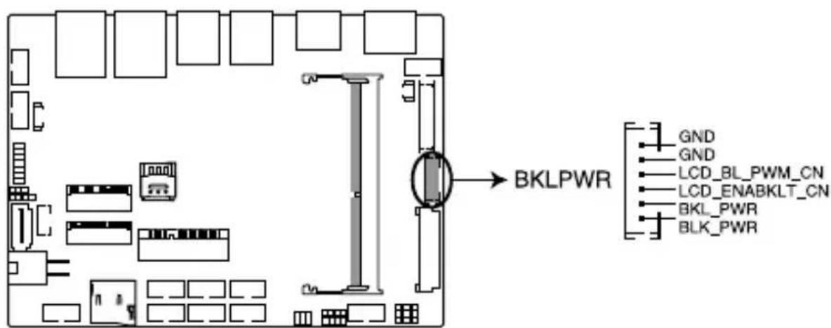
Backlight Inverter Power connector
Connector type
WAFER 6P 2.0mm pitch NATURAL S/T
10. Low Pin Count connector
The Low Pin Count connector allows you to connect a low pin count (LPC) debug card that offers a faster, more efficient motherboard troubleshooting solution. When connected to a debug card, users can view error and debugging codes on the card and get a better idea of initialization and recovery processes.
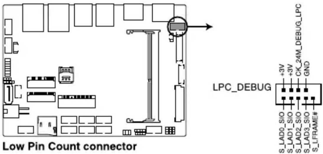
Connector type
BOX header 2x5p, K10, 2.0mm pitch
11. Battery connector
The Battery connector allows you to connect the lithium CMOS battery.
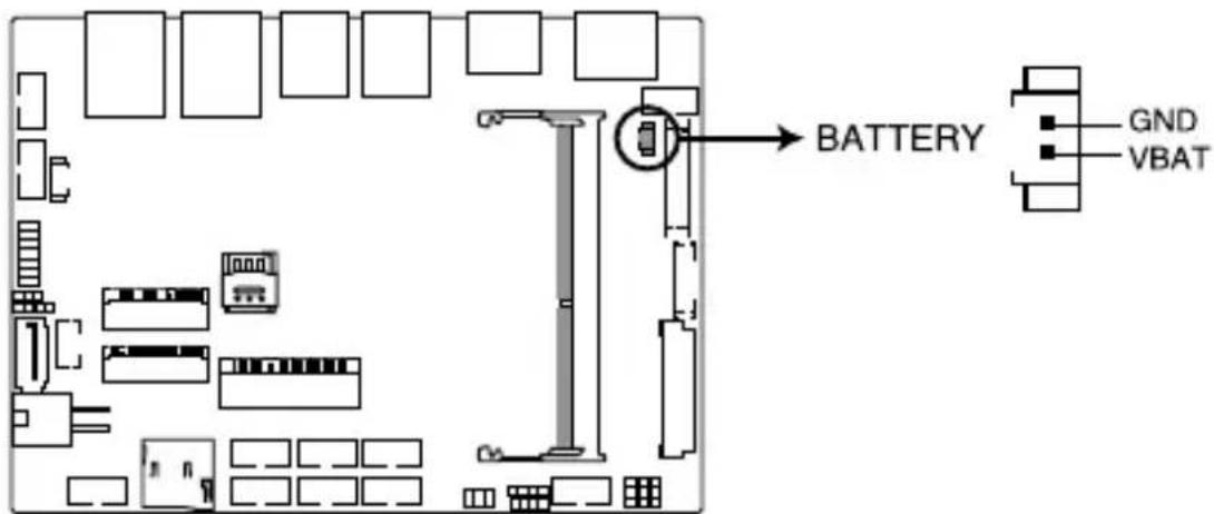
Battery connector
12. EDP Signal connector (on selected models)
The EDP Signal connector allows you to connect an internal embedded DisplayPort.

Connector type
WtoB CON 40P 0.5MM,R/A
ACES/88341-4001
13. System Management Bus connector
The System Management Bus (SMBus) connector allows you to connect SMBus devices. This connector is generally used for communication with the system and power management-related tasks.
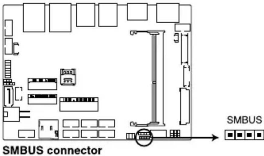
Connector type
Header 1x4p, 2.0mm pitch
14. GPIO connector
The GPIO connector allows you to connect a general purpose input/output module which allows you to customize the digital signal input/output.
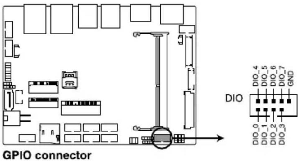
Connector type
BOX header 2x5p, K9, 2.0mm pitch
15. I2C connector
The I2C (Inter-Integrated Circuit)connector allows you to connect an I2C compatible IoT security module.
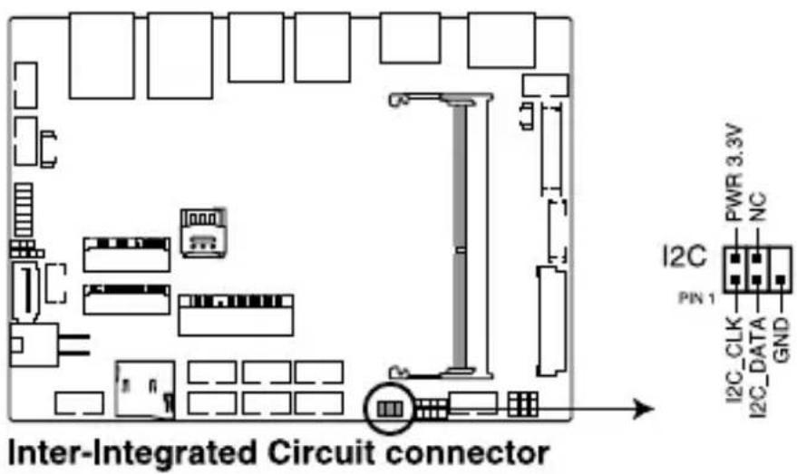
Connector type
Header 2x3p, K6, 2.0mm pitch
16. SPI TPM connector
The SPI TPM connector supports a Trusted Platform Module (TPM) system, which can securely store keys, digital certificates, passwords, and data. A TPM system also helps enhance network security, protects digital identities, and ensures platform integrity.
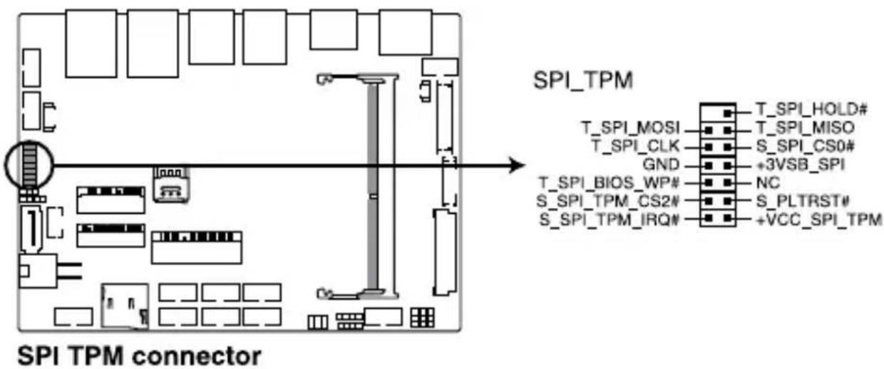
Connector type
Header 2x7p,K14, 2.0mm pitch
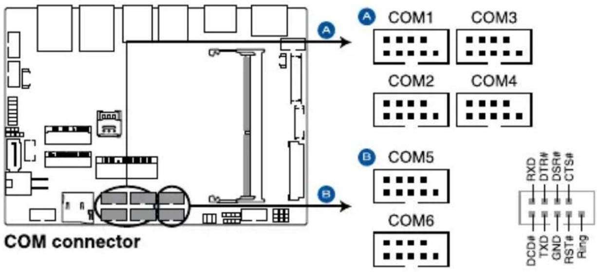
17. Serial Port connector
The Serial (COM) Port connector allows you to connect a serial port module. Connect the serial port module cable to this connector, then install the module to a slot opening on the system chassis.
flowchart
graph TD
    subgraph COM Connector
        A["Component A"] --> B["COM1"]
        A --> C["COM2"]
        A --> D["COM3"]
        A --> E["COM4"]
        A --> F["COM5"]
        A --> G["COM6"]
    end
    subgraph COM Connector
        B --> H["RD0"]
        C --> I["DTR#"]
        D --> J["DSR#"]
        E --> K["RST#"]
        F --> L["Ring"]
        G --> M["RD0"]
        G --> N["TXD"]
        G --> O["GND"]
    end
    style COM Connector fill:#f9f,stroke:#333
    style COM1 fill:#ccf,stroke:#333
    style COM2 fill:#ccf,stroke:#333
    style COM3 fill:#ccf,stroke:#333
    style COM4 fill:#ccf,stroke:#333
    style COM5 fill:#ccf,stroke:#333
    style COM6 fill:#ccf,stroke:#333
Connector type
BOX header 2x5p, K10, 2.0mm pitch
NOTE:
- The serial port module is purchased separately.
• COM1 and COM2 support RS-232/422/485.
• COM 3, COM4, COM5, and COM6 support RS-232.
18. USB 2.0 connector
The USB 2.0 connector allows you to connect a USB module for additional USB 2.0 ports. The USB 2.0 connector provides data transfer speeds of up to 480 MB/s connection speed.
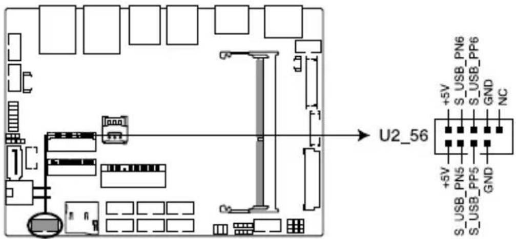
USB 2.0 connector
Connector type
BOX header 2x5p, K9, 2.0mm pitch
WARNING! DO NOT connect a 1394 cable to the USB connectors. Doing so will damage the motherboard!
NOTE: The USB 2.0 module is purchased separately.
19. Chassis Intrusion connector
The Chassis Intrusion connector allows you to connect a intrusion sensor or microswitch for the chassis intrusion detection feature. When you remove any chassis component, the sensor or microswitch triggers and sends a high level signal and records a chassis intrusion event.
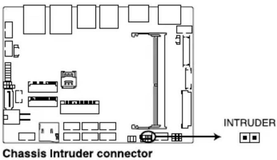
NOTE: By default, a jumper cap that disables the intrusion detection feature is installed on the connector to prevent accidental triggers.
20. Fan connector
The Fan connector allows you to connect a fan to cool the system.
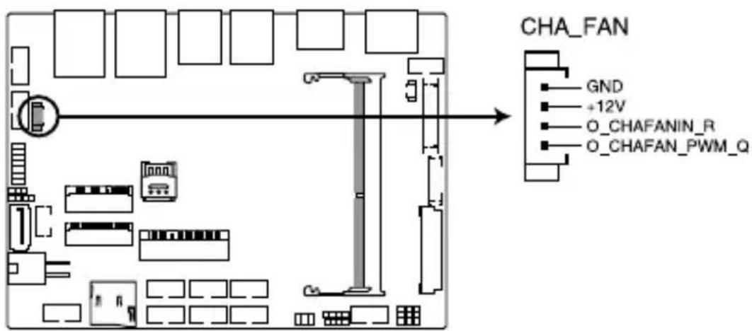
FAN connector
Connector type
WtoB CON 4P,1.25mm,S/T
WARNING!
- DO NOT forget to connect the fan cable to the fan connector. Insufficient air flow inside the system may damage the motherboard components. These are not jumpers! Do not place jumper caps on the fan connectors!
- Ensure the cable is fully inserted into the connector.
21. System Panel connector
The System Panel connector supports several chassis-mounted functions.
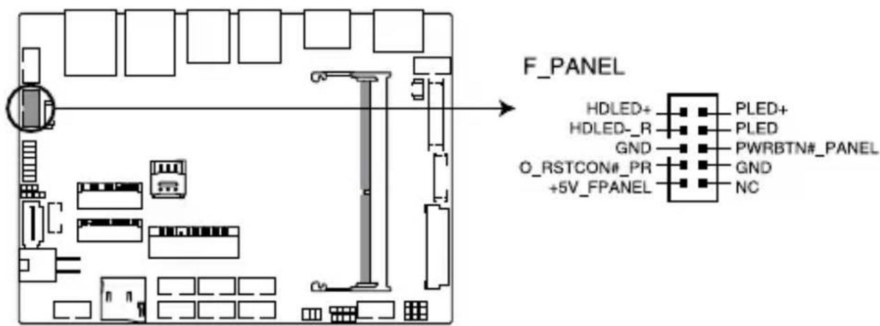
Front Panel connector
Connector type
BOX header 2x5p 2.0mm pitch
• System Power LED connector (PLED)
The 2-pin connector allow you to connect the System Power LED. The System Power LED lights up when the system is connected to a power source, or when you turn on the system power, and blinks when the system is in sleep mode.
• Storage Device Activity LED connector (HDLED)
The 2-pin connector allows you to connect the Storage Device Activity LED. The Storage Device Activity LED lights up or blinks when data is read from or written to the storage device or storage device add-on card.
• Power Button/Soft-off Button connector (PWRBTN)
The 3-1 pin connector allows you to connect the system power button. Press the power button to power up the system, or put the system into sleep or soft-off mode (depending on the operating system settings).
- Reset button connector (O\_RSTCON)
The 2-pin connector allows you to connect the chassis-mounted reset button. Press the reset button to reboot the system.
22. Line Out / Mic connector
The Line Out / Mic connector is for a line out / microphone module that supports HD Audio. Connect one end of the line Out / mic module cable to this connector.
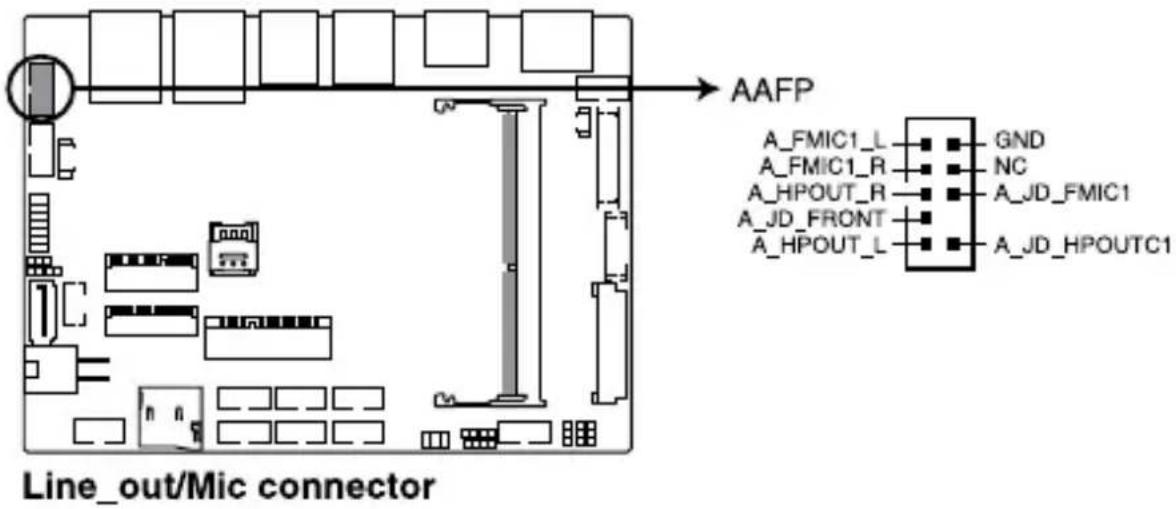
Connector type
BOX header 2x5p, K8, 2.0mm pitch
NOTE: We recommend that you connect a high-definition line out / mic module to this connector to avail of the motherboard's high- definition audio capability.
23. DC-in 4-Pin Power connector
The DC-in 4-pin Power connector is for DC power input. Using a compatible power cable and power board, you may connect a suitable power supply with DC-in jacks.
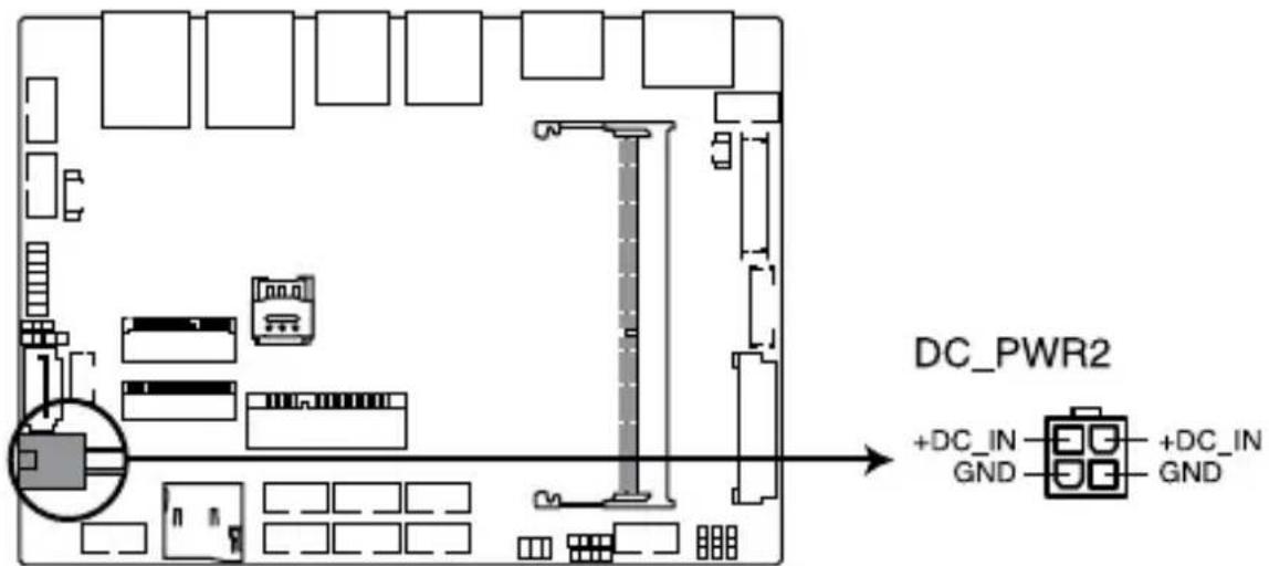
DC-in 4-pin Power connector
Connector type
POWER CON 4P R/A
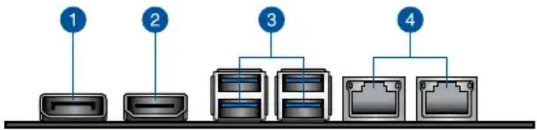
2.6 I/O connectors
Front panel
flowchart
graph LR
    A["1"] --> B["Printer"]
    C["2"] --> D["Printer"]
    E["3"] --> F["Server"]
    G["4"] --> H["Router"]
Front panel connectors
| 1. DisplayPort |
| 2. HDMI port |
| 3. USB 3.2 Gen 1 ports |
| 4. LAN (RJ-45) ports |
3
Upgrading your Single Board Computer
IMPORTANT!
- Ensure that your hands are dry before proceeding with the rest of the installation process. Before installing any of the features in this guide, use a grounded wrist strap or touch a safely grounded object or metal object to avoid damaging them due to static electricity.
- Turn off the power of your Single Board Computer, and allow it to cool for at least 10 minutes before performing any installation/uninstallation process.
NOTE: The illustrations in this section are for reference only. The slots may vary depending on model.
3.1 Installing memory modules
Your motherboard comes with a SO-DIMM memory slot that allow you to install a DDR3L SO-DIMM.
Align and insert the memory module into the slot (A) and press it down (B) until it is securely seated in place.
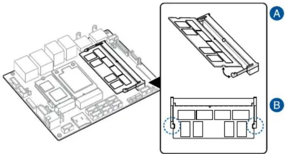
natural_image
Technical diagram showing a 3D layout of electronic components and a multi-layered device with labeled sections A and B (no text or symbols on the diagram itself)3.2 Installing 2.5" storage device
- Connect the storage device cable to the storage device.
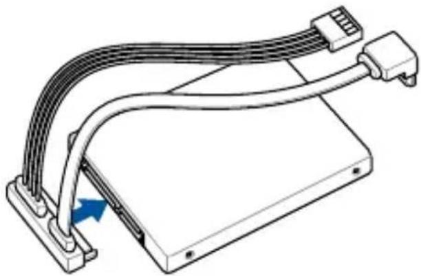
natural_image
Technical line drawing of a mechanical device with multiple wires and connectors, showing a blue arrow indicating a specific component (no text or symbols present)- Connect the storage device cable to the SATA6G and SATA_PWR connectors on the motherboard.
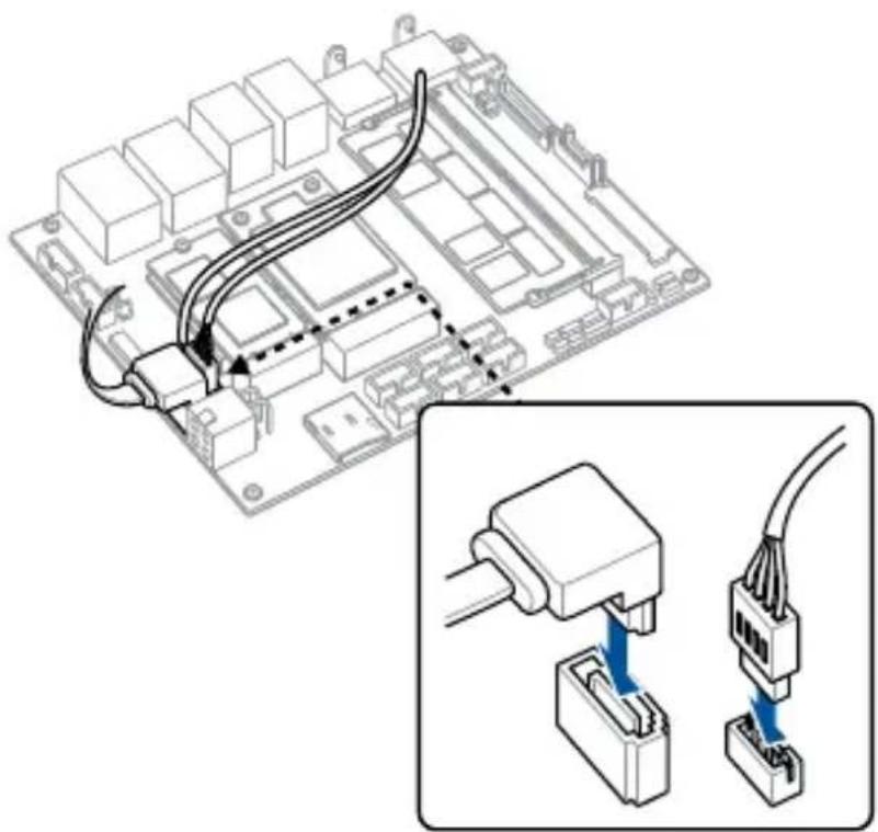
natural_image
Diagram of a computer motherboard with connected cables and connectors, showing internal wiring connections (no text or labels)3.3 Installing the Mini PCIe card
Your motherboard comes with a Mini PCIe slot that allows you to install a Mini PCIe peripheral card.
Align and insert the Mini PCIe card into the slot (A) and press it down and secure it in place using two (2) screws (B).
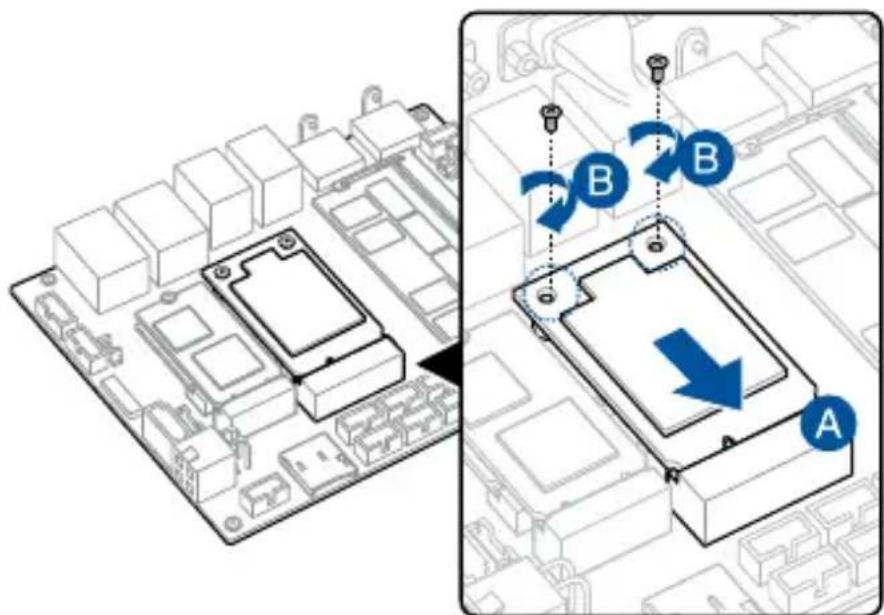
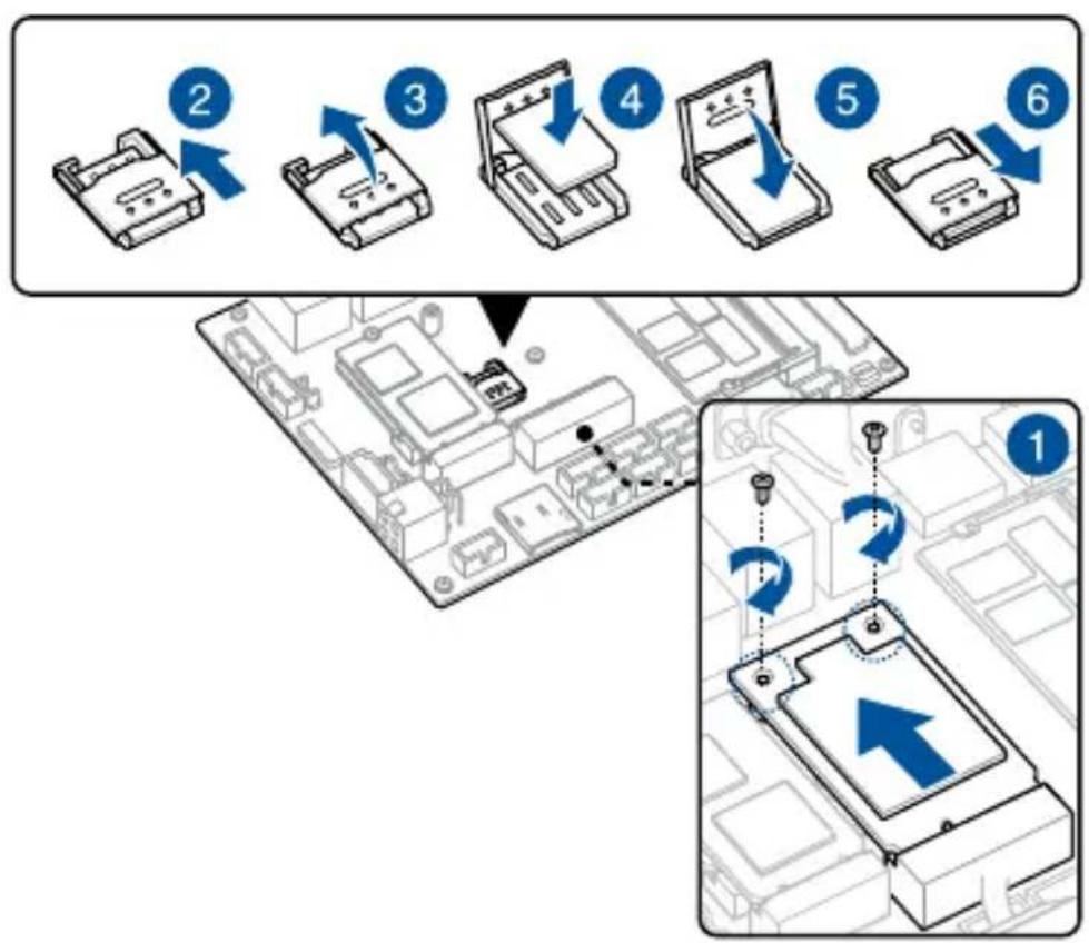
3.4 Installing a Nano SIM card
- (optional) Remove the Mini PCIe card if there is a Mini PCIe card installed by removing the two (2) screws securing the Mini PCIe card first, then removing the Mini PCIe card.
- Push the Nano SIM cover towards the front I/O of your motherboard.
- Lift the Nano SIM cover.
- Place the Nano SIM into the Nano SIM slot.
- Replace the Nano SIM cover.
- Push the Nano SIM cover towards the rear of your motherboard to secure the Nano SIM card.
flowchart
graph TD
    A["Step 1: Initial Board with PC"] --> B["Step 2: Insert PC to form an electronic component"]
    B --> C["Step 3: Insert PC to form a laptop with a printer"]
    C --> D["Step 4: Insert PC to form a tablet device"]
    D --> E["Step 5: Insert PC to form a hard disk"]
    E --> F["Step 6: Insert PC to form a hard disk with a printer"]
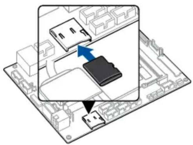
3.5 Installing an Micro SD card
Insert your Micro SD card into the Micro SD card slot. Ensure that the Micro SD card is pushed all the way into the Micro SD card slot.
natural_image
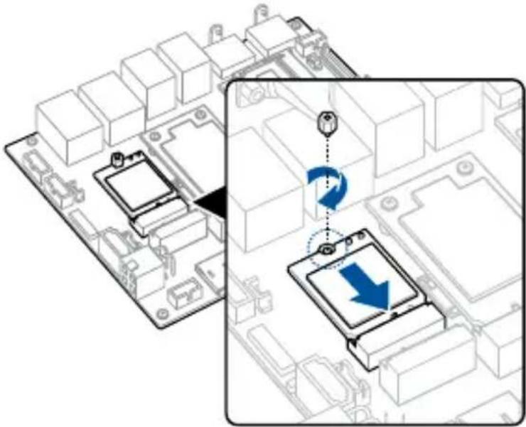
Isometric view of a computer motherboard with a highlighted internal component (no text or symbols)3.6 Installing the wireless card
-
Remove the M.2 stand screw.
-
Align and insert the wireless card into its slot on the motherboard, then gently push down the wireless card on top of the screw hole and fasten it using the previously removed stand screw.
natural_image
Diagram showing a computer motherboard with an inset view of a device's rotation and movement (no text or symbols)- (optional) Connect the antennas to your wireless card.
NOTE:
- Connecting antennas to your wireless card may strengthen the wireless signal.
- A soft clicking sound indicates that the antenna has been securely attached on the wireless card.
• The antennas are purchased separately.
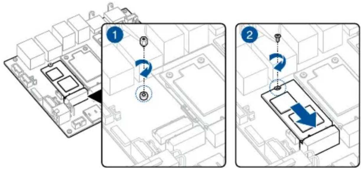
3.7 Installing an M.2 SSD
-
(optional) Replace the stand screw if it has been removed.
-
Align and insert the M.2 SSD into its slot inside the Single Board Computer, then gently push down the M.2 SSD on top of the stand screw hole and fasten it using a screw.
3.8 Installing a heatsink
- Place the heatsink with its fins faced down on a flat surface.
- Place the motherboard over the heatsink so that the five (5) screw holes on the motherboard are aligned to the five (5) standoffs on the heatsink as shown below.
- Secure the motherboard to the heatsink using the five (5) spring screws bundled with the heatsink in the sequence shown below.
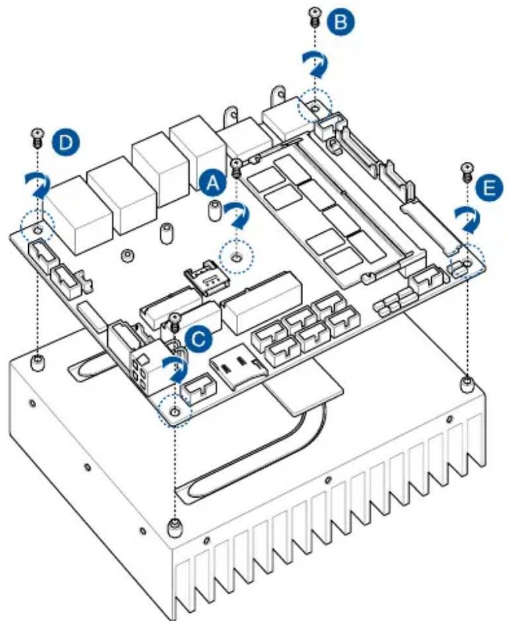
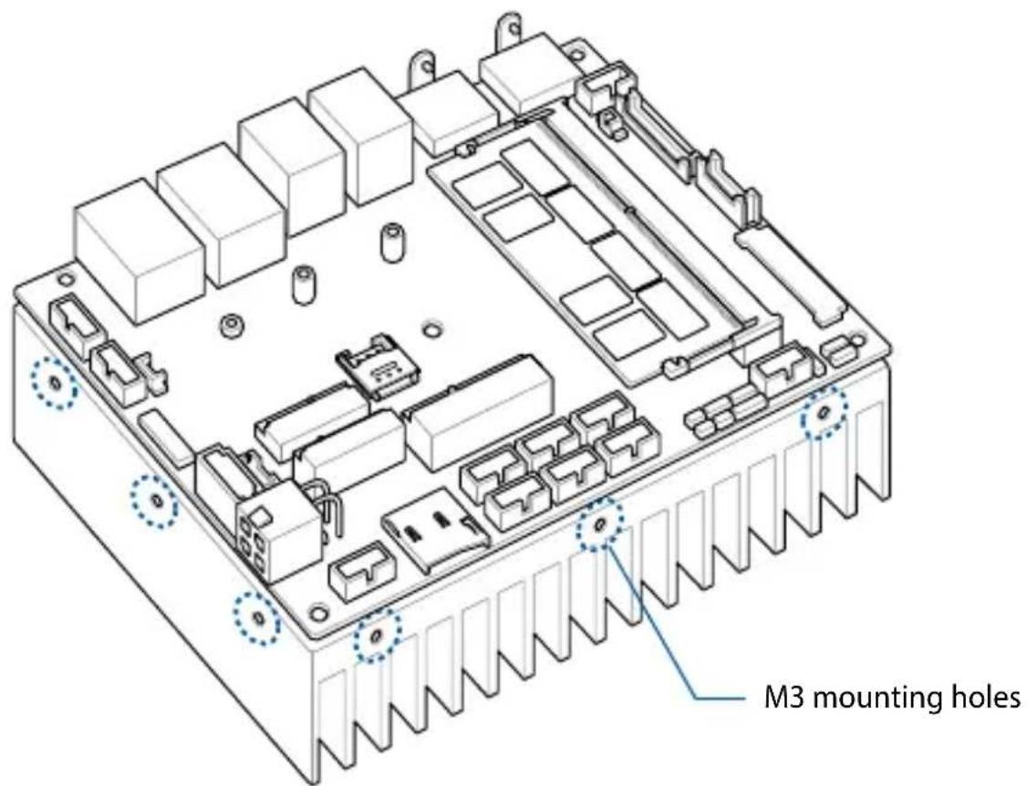
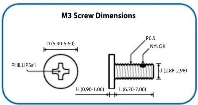
- (optional) Attach the heatsink and motherboard assembly to your chassis using the M3 mounting holes along the four sides of the heatsink together with the bundled M3 screws.
NOTE: A total of twelve (12) mounting holes are provided for more flexibility in attaching the assembly to your chassis.
3.9 Installing a heat spreader
- Place the heat spreader with its copper pad and thermal interface material facing up on a flat surface.
- Remove the plastic protective film from the copper pad and thermal interface material on the heat spreader, if there is one.
- Orient the motherboard so that the CPU and chipset on its backside are in direct contact with the copper pad on the heat spreader, and the five (5) screw holes on the motherboard are aligned to the five (5) standoffs on the heat spreader.
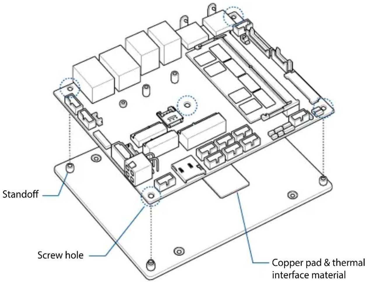
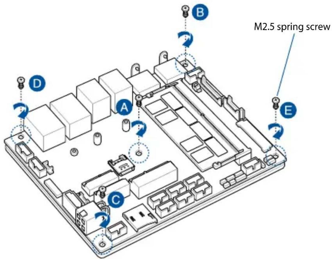
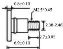
- Secure the motherboard to the heat spreader using the five (5) M2.5 spring screws bundled with the heat spreader in the sequence shown below.
M2.5 Spring Screw Dimensions


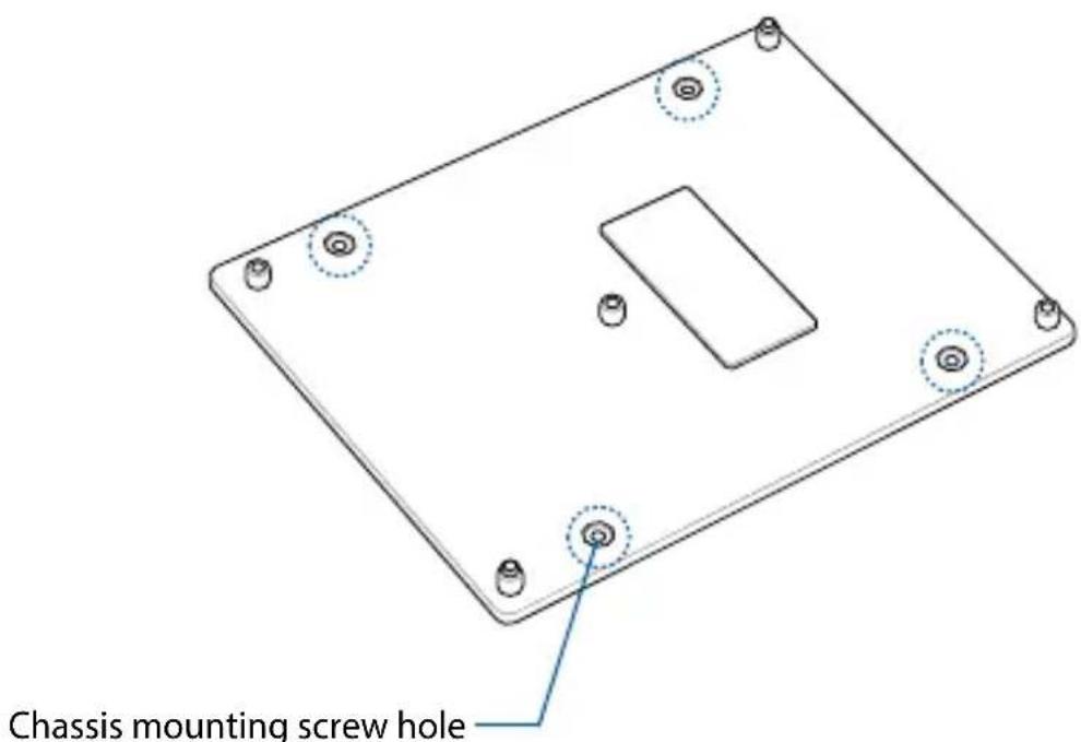
- Mount the motherboard and heat spreader assembly to the chassis using four (4) M2.5 screws to the four (4) chassis mounting screw holes on the heat spreader. Refer to the illustration below for the location of the chassis mounting screw holes.
BIOS Setup
4
4.1 Getting to know your BIOS
The BIOS (Basic Input and Output System) stores system hardware settings such as Storage Device Configuration, Advanced Power Management, and Boot Device Configuration that are needed for system startup. Under normal circumstances, the default BIOS settings apply to most conditions to ensure optimal performance. DO NOT change the default BIOS settings except in the following circumstances:
- An error message appears on the screen during the system bootup and requests you to run the BIOS setup.
- You have installed a new system component that requires further BIOS settings or update.
WARNING! Inappropriate BIOS settings may result to instability or boot failure. We strongly recommend that you change the BIOS settings only with the help of a trained service personnel.
4.2 BIOS setup program
Use the BIOS Setup program to update the BIOS or configure its parameters. The BIOS screens include navigation keys and brief online help to guide you in using the BIOS Setup program.
Entering BIOS Setup at startup
To enter BIOS Setup at startup:
- Press
Entering BIOS Setup after POST
To enter BIOS Setup after POST:
- Press
- Press the power button to turn the system off then back on. Do this option only if you failed to enter BIOS Setup using the first option.
BIOS menu screen
This section provides a brief introduction of the BIOS Interface of your Single Board Computer.
Configuration fieldsMenu items General helpMenu bar
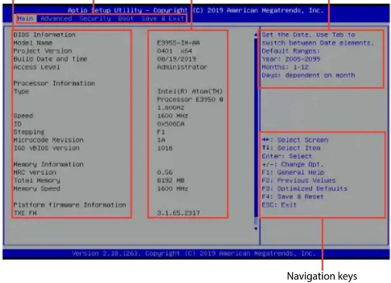
Menu bar
The menu bar on top of the screen has the following main items:
| Main For changing the basic system configuration |
| Advanced For changing the advanced system settings |
| Security For changing the security settings |
| Boot For changing the system boot configuration |
| Save & Exit For selecting the save and exit options or loading default settings |
4.3 Main Menu
When you enter the BIOS Setup program, the Main menu screen appears. The Main menu provides you an overview of the basic system information, and allows you to set the system date and time. Scroll down to display the other BIOS items.
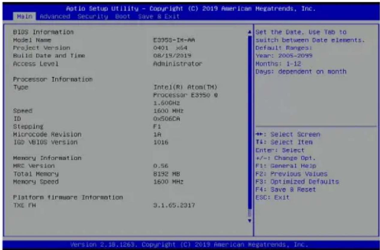
4.3.1 System Date [Day xx/xx/xxxx]
Allows you to set the system date.
4.3.2 System Time [xx:xx:xx]
Allows you to set the system time.
4.4 Advanced menu
The Advanced menu items allow you to change the settings for the CPU and other system devices.
WARNING! Be cautious when changing the settings of the Advanced menu items. Incorrect field values can cause the system to malfunction.
![Aptio Setup Utility - Copyright (C) 2019 American Megatrends, Inc. Main Advanced Security Boot Save & Exit Start ASUS EzFlash OS Type [Other OS] ► Trusted Computing ► PCH Storage Configuration ► Onboard Devices Configuration ► ACPI Settings ► APM Configuration ► SMART Settings ► NCT6116D Super IO Configuration ► NCT6116D HM Monitor ► Serial Port Console Redirection ► CPU Configuration ► PCI Subsystem Settings ► USB Configuration ► Network Stack Configuration ► SDIO Configuration ► Platform Trust Technology ► Security Configuration ► LFP Configuration ► Thermal Trusted Computing Settings +: Select Screen T#: Select Item Enter: Select +/-: Change Opt. F1: General Help F2: Previous Values F3: Optimized Defaults F4: Save & Reset ESC: Exit Version 2.18.1263. Copyright (C) 2019 American Megatrends, Inc.](/content/2026/06/1175753/images/3c142eb7a3574fc536c783f164268be3cf0d1cf5848f81a6e16a176d39dde747.jpg)
Start ASUS EzFlash
Allows you to run ASUS EzFlash BIOS ROM Utility when you press
WARNING! Ensure to back up your Bitlocker recovery key and suspend Bitlocker encryption in the operating system before updating your BIOS.
NOTE: For more details, refer to section 4.8.2 ASUS EzFlash Utility.
OS Type
Allows you to select your installed operating system.
Execute the Microsoft® Secure Boot check. Only select this option when booting on Windows® UEFI mode or other Microsoft® Secure Boot compliant OS.
[Other OS] Get the optimized function when booting on
Windows ^® non-UEFI mode. Microsoft ^® Secure Boot only supports Windows ^® UEFI mode.
4.4.1 Trusted Computing
| Aptio Setup Utility - Copyright (C) 2019 American Megatrends, Inc. Advanced | |
| TPM20 Device Found Security Device Support [Enable] Active PCR banks SHA-1, SHA256 Available PCR banks SHA-1, SHA256 | Enables or Disables BIOS support for security device. O.S. will not show Security Device. TCG EFI protocol and INT1A interface will not be available. |
| SHA-1 PCR Bank [Enabled] SHR256 PCR Bank [Enabled] | |
| Pending operation [None] Platform Hierarchy [Enabled] Storage Hierarchy [Enabled] Endorsement Hierarchy [Enabled] | |
| TPM2.0 UEFI Spec Version [TCG_2] Physical Presence Spec Version [1.3] | +: Select Screen T↓: Select Item Enter: Select |
NOTE: All values changed here do not take effect until computer is restarted.
Security Device Support
Allows you to enable or disable the BIOS support for security device.
Configuration options: [Disable] [Enable]
NOTE: The following items appear only when Security Device Support is set to [Enabled].
SHA-1 PCR Bank
Allows you to enable or disable SHA-1 PCR Bank. Configuration options: [Disable] [Enable]
SHA256 PCR Bank
Allows you to enable or disable SHA256 PCR Bank. Configuration options: [Disable] [Enable]
Pending operation
Allows you to schedule an operation for the Security Device. Configuration options: [None] [TPM Clear]
NOTE: Your computer will reboot during restart in order to change the state of Security Device.
Platform Hierarchy
Allows you enable or disable the Platform Hierarchy. Configuration options: [Disabled] [Enabled]
Storage Hierarchy
Allows you enable or disable the Storage Hierarchy. Configuration options: [Disabled] [Enabled]
Endorsement Hierarchy
Allows you enable or disable the Endorsement Hierarchy. Configuration options: [Disabled] [Enabled]
TPM2.0 UEFI Spec Version
Allows you to select the TCG2 spec version support. [TCG_1_2] Compatible mode for Windows 8 ^ / Windows ^ 10. [TCG_2] Supports new TCG2 protocol and event format for Windows ^ 10 or later.
Physical Presence Spec Version
Select to tell the OS to support PPI Spec Version 1.2 or 1.3. Configuration options: [1.2] [1.3]
NOTE: Some HCK tests might not support version 1.3.
4.4.2 PCH Storage Configuration
While entering Setup, the BIOS automatically detects the presence of SATA devices. The SATA Port items show [Empty] if no SATA device is installed to the corresponding SATA port.
| Aptio Setup Utility - Copyright (C) 2019 American Megatrends, Inc. Advanced | ||
| PCH Storage Configuration SATA Controller SMART Self Test Aggressive LPM Support SATA6G Software Preserve SATA6G Port SATA6G Port Hot Plug M.2(SOCKET3) Software Preserve M.2(SOCKET3) Port M.2(SOCKET3) Port Hot Plug | [Enable] [Disabled] [Disabled] TS128GSSD4201 (128.0GB) Unknown [Enabled] [Disabled] [Not Installed] Unknown [Enabled] [Disabled] | Enables or Disobles the Chipset SATA Controller. ++: Select Screen T1: Select Iten Enter: Select +/-: Change Opt. F1: General Help |
SATA Controller
Allows you to enable or disable the Chipset SATA Controller. Configuration options: [Disabled] [Enabled]
SMART Self Test
SMART (Self-Monitoring, Analysis and Reporting Technology) is a monitoring system that shows a warning message during POST (Power-On Self Test) when an error occurs in the hard disks. Configuration options: [Disabled] [Enabled]
NOTE: The following items appear only when SATA Port Enable is set to [Enabled].
Aggressive LPM Support
This item is designed for LPM (link power management) support with a better energy saving conditions.
Configuration options: [Disabled] [Enabled]
SATA6G
SATA6G Port
Allows you to enable or disable the SATA port.
Configuration options: [Disabled] [Enabled]
SATA6G Port Hot Plug
Allows you to enable or disable SATA Hot Plug Support.
Configuration options: [Disabled] [Enabled]
M.2(SOCKET3)
M.2(SOCKET3) Port
Allows you to enable or disable the M.2(SOCKET3) port.
Configuration options: [Disabled] [Enabled]
M.2(SOCKET3) Port Hot Plug
Allows you to enable or disable M.2(SOCKET3) Hot Plug Support.
Configuration options: [Disabled] [Enabled]
4.4.3 Onboard Devices Configuration
![Aptio Setup Utility - Copyright (C) 2019 American Megatrends, Inc. Advanced HD-Audio Support [Enable] Intel LAN [Enable] Intel LAN PXE Option ROM [Disable] Intel LAN 2 [Enable] Intel LAN 2 PXE Option ROM [Disable] M.2 WiFi(E-Key) PCIE Port [Enabled] USB Port [Enabled] Mini PCIe PCIE Port [Enabled] USB Port [Enabled] I2C Controller [Enable] ► 10 Expander Configuration Enable/Disable MD-Audio Support ◆: Select Screen ↑: Select Item](/content/2026/06/1175753/images/a5888da34f3d423f680a37f5d7c18c07cf33bd42d3185a76a6ecf68b224dc0db.jpg)
HD Audio Support
Allows you to enable or disable HD-Audio support.
Configuration options: [Disabled] [Enabled]
Intel LAN
Allows you to enable or disable Intel LAN.
Configuration options: [Disabled] [Enabled]
NOTE: The following item appears only when Intel LAN is set to [Enabled].
Intel LAN PXE Option ROM
Allows you to enable or disable Intel LAN PXE OPROM launch.
Configuration options: [Disabled] [Enabled]
Intel LAN 2
Allows you to enable or disable Intel LAN 2.
Configuration options: [Disabled] [Enabled]
Intel LAN 2 PXE Option ROM
Allows you to enable or disable Intel LAN 2 PXE OPROM launch.
Configuration options: [Disabled] [Enabled]
M.2 WiFi(E-Key)
PCIE Port
Allows you to enable or disable Wi-Fi Controller.
Configuration options: [Disabled] [Enabled]
USB Port
Allows you to enable or disable Bluetooth Controller.
Configuration options: [Disabled] [Enabled]
Mini PCIe
PCIE Port
Allows you to enable or disable PCIe Controller.
Configuration options: [Disabled] [Enabled]
USB Port
Allows you to enable or disable USB Controller.
Configuration options: [Disabled] [Enabled]
I2C Controller
Allows you to enable or disable I2C Controller Support.
Configuration options: [Disabled] [Enabled]
IO Expander Configuration
IO Expander GPIO 0-7
Direction
Allows you to select the direction of the GPIO.
Configuration options: [Output] [Input]
4.4.4 ACPI Settings
The items in this menu allow you to configure the system ACPI parameters.
![Aptio Setup Utility - Copyright (C) 2019 American Megatrends, Inc. Advanced ACPI Settings Enable ACPI Auto Configuration [Disabled] Enable Hibernation [Enabled] ACPI Sleep State [S3 (Suspend to RAM)] Lock Legacy Resources [Disabled] Enables or Disables BIOS ACPI Auto Configuration.](/content/2026/06/1175753/images/9f6ffe21f908e233396743786f5e117c7fa4247224499380eff58ff3306a0bd6.jpg)
Enable ACPI Auto Configuration
Allows you to enable or disable the BIOS ACPI Auto Configuration. Configuration options: [Disabled] [Enabled]
NOTE: The following item appears only when Enable ACPI Auto Configuration is set to [Disabled].
Enable Hibernation
Allows you to enable or disable the ability of the system to hibernate (OS/S4 Sleep State). Configuration options: [Disabled] [Enabled]
IMPORTANT! This option may be not be effective with some OS.
ACPI Sleep State
Allows you to select the highest ACPI sleep state the system will enter when the SUSPEND button is pressed. Configuration options: [Suspend Disabled] [S3 (Suspend to RAM)]
Lock Legacy Resources
Allows you to enable or disable the Lock of Legacy Resources. Configuration options: [Disabled] [Enabled]
4.4.5 APM Configuration
Allows you to configure the Advance Power Management (APM) settings.
![Aptio Setup Utility - Copyright (C) 2019 American Megatrends, Inc. Advanced ErP Ready (Disabled) Restore AC Power Loss (S5 State) Power On By PCI-E [Disabled] Power On By Ring [Disabled] Power On By RTC [Disabled] Allow BIOS to switch off some power at S4/S5 to get the system ready for ErP requirement. When set to Enabled, all other PMF options will be switched off. RGB LEDs and RGB/Addressable RGB Headers will also be](/content/2026/06/1175753/images/b57f94e78e2918f451a3a523ec4dd9a01703527826f82b397208d9c06a4a4c36.jpg)
ErP Ready
Allows you to switch off some power at S4+S5 or S5 to get the system ready for ErP requirement. When set to [Enabled], all other PME options will be switched off.
Configuration options: [Disabled] [Enabled(S4+S5) [Enabled(S5)]
Restore AC Power Loss
[S0] The system goes into ON state after an AC power loss.
[S5] The system goes into OFF state after an AC power loss.
[Last State] The system goes into either OFF or ON state, whatever the system state was before the AC power loss.
Power On By PCI-E
Allows you to enable or disable the wake-on-LAN function for the onboard LAN controller or other installed PCI-E LAN cards.
Configuration options: [Disabled] [Enabled]
Power On By Ring
[Disabled] Disables the Ring devices to generate a wake event.
[Enabled] Enables the Ring devices to generate a wake event.
Power On By RTC
[Disabled] Disables RTC to generate a wake event.
[Enabled] When set to [Enabled], the items RTC Alarm Date (Days) and Hour/Minute/Second will become user-configurable with set values.
4.4.6 SMART Settings
The items in this menu allow you to configure the SMART Self Test settings.
![Aptio Setup Utility - Copyright (C) 2019 American Megatrends, Inc. Advanced SMART Settings SMART Self Test [Disabled] Run SMART Self Test on all HDDs during POST.](/content/2026/06/1175753/images/acdc85eaedac24024c97cd35d16975de9e96cba967b1930516e4958c2335d3f1.jpg)
SMART Self Test
Allows you to run SMART Self Test on all HDDs during POST. Configuration options: [Disabled] [Enabled]
4.4.7 NCT6116D Super IO Configuration
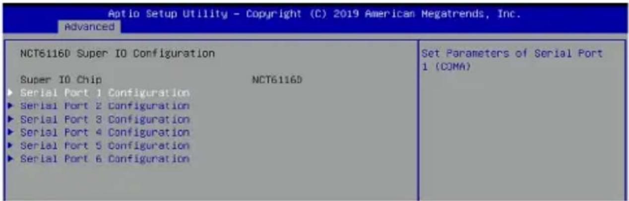
Serial Port 1-2 Configuration
Allows you to set the parameters of Serial Port 1-2.
Serial Port
Allows you to enable or disable Serial Port. Configuration options: [Disabled] [Enabled]
NOTE: The following items appear only when Serial Port is set to [Enabled].
Mode Select
Configuration options: [RS232] [RS485] [RS422]
Change Settings
Allows you to choose the setting for Super IO device.
Configuration options: [Auto] [IO=3F8h; IRQ=4;] [IO=3F8h; IRQ=3, 4, 5, 6, 7, 9, 10, 11, 12;] [IO=2F8h; IRQ=3, 4, 5, 6, 7, 9, 10, 11, 12;] [IO=3E8h; IRQ=3, 4, 5, 6, 7, 9, 10, 11, 12;]
Serial Port 3-6 Configuration
Allows you to set the parameters of Serial Port 3-6.
Serial Port
Allows you to enable or disable Serial Port.
Configuration options: [Disabled] [Enabled]
NOTE: The following items appear only when Serial Port is set to [Enabled].
Change Settings
Allows you to choose the setting for Super IO device.
Configuration options: [Auto] [IO=3F8h; IRQ=4;] [IO=3F8h; IRQ=3, 4, 5, 6, 7, 9, 10, 11, 12;] [IO=2F8h; IRQ=3, 4, 5, 6, 7, 9, 10, 11, 12;] [IO=3E8h; IRQ=3, 4, 5, 6, 7, 9, 10, 11, 12;]
4.4.8 NCT6116D HW Monitor
| Aotio Setup Utility - Copyright (C) 2019 American Megatrends, Inc. Advanced | |
| PC Health Status | |
| MotherBoard Temperature : +35.5°C CPU Temperature : +34.0°C CHA_FAN_IN : N/A VCORE : +0.896 V +5VSE_IN : +5.093 V System Current : +0.300 A DC_IN : +19.488 V VTT : +1.056 V | |
4.4.9 Serial Port Console Redirection
![Aptio Setup Utility - Copyright (C) 2019 American Megatrends, Inc. Advanced COM1 Console Redirection [Disabled] ► Console Redirection Settings COM2 Console Redirection [Disabled] ► Console Redirection Settings COM3 Console Redirection [Disabled] ► Console Redirection Settings COM4 Console Redirection [Disabled] ► Console Redirection Settings COM5 Console Redirection [Disabled] ► Console Redirection Settings COM6 Console Redirection [Disabled] ► Console Redirection Settings Console Redirection Enable or Disable. ++: Select Screen T↓: Select Item Enter: Select +/-: Change Opt. F1: General Help F2: Previous Values F3: Optimized Defaults F4: Save & Reset ESC: Exit](/content/2026/06/1175753/images/ce031cbfa08f1aecbff4e4b8f184a7af4b00f3f669dc476649a3fd975559d93e.jpg)
COM1-6
Console Redirection
Allows you to enable or disable the console redirection feature.
Configuration options: [Disabled] [Enabled]
NOTE: The following item appears only when Console Redirection is set to [Enabled].
Console Redirection Settings
This item becomes configurable only when you enable the Console Redirection item. The settings specify how the host computer and the remote computer (which the user is using) will exchange data. Both computers should have the same or compatible settings.
Terminal Type
Allows you to set the terminal type.
[VT100] ASCII char set.
[VT100+] Extends VT100 to support color, function keys, etc.
[VT-UTF8] Uses UTF8 encoding to map Unicode chars onto 1 or more bytes.
[ANSI] Extended ASCII char set.
Bits per second
Selects serial port transmission speed. The speed must be matched on the other side. Long or noisy lines may require lower speeds.
Configuration options: [9600] [19200] [38400] [57600] [115200]
Data Bits
Configuration options: [7] [8]
Parity
A parity bit can be sent with the data bits to detect some transmission errors. [Mark] and [Space] parity do not allow for error detection.
[None] None.
[Even] parity bit is 0 if the num of 1's in the data bits is even.
[Odd] parity bit is 0 if num of 1's in the data bits is odd.
[Mark] parity bit is always 1.
[Space] parity bit is always 0.
Stop Bits
Stop bits indicate the end of a serial data packet. (A start bit indicates the beginning.) The standard setting is 1 stop bit. Communication with slow devices may require more than 1 stop bit.
Configuration options: [1] [2]
Flow Control
Flow control can prevent data loss from buffer overflow. When sending data, if the receiving buffers are full, a "stop" signal can be sent to stop the data flow. Once the buffers are empty, a "start" signal can be sent to re-start the flow. Hardware flow control uses two wires to send start/stop signals.
Configuration options: [None] [Hardware RTS/CTS]
VT-UTF8 Combo Key Support
Allows you to enable the VT-UTF8 Combo Key Support for ANSI/VT100 terminals.
Configuration options: [Disabled] [Enabled]
Recorder Mode
With this mode enabled only text will be sent. This is to capture Terminal data.
Configuration options: [Disabled] [Enabled]
Resolution 100x31
Allows you to enable or disable extended terminal resolution.
Configuration options: [Disabled] [Enabled]
Putty Keypad
This allows you to select the FunctionKey and Keypad on Putty.
Configuration options: [VT100] [Intel Linux] [XTERMR6] [SCO] [ESCN] [VT400]
Legacy Console Redirection Settings
Redirection COM Port
Allows you to select a COM port to display redirection of Legacy OS and Legacy OPROM Messages.
Configuration options: [COM1] [COM2] [COM3] [COM4] [COM5] [COM6]
Resolution
This allows you to set the number of rows and columns supported on the Legacy OS.
Configuration options: [80x24] [80x25]
Redirection After POST
This setting allows you to specify if Bootloader is selected than Legacy console redirection.
[Always Enable] Legacy Console Redirection is enabled for Legacy OS.
[Bootloader] Legacy Console Redirection is disabled before booting to Legacy OS.
Serial Port for Out-of-Band Management/Windows Emergency Management Services (EMS)
Console Redirection
Allows you to enable or disable the console redirection feature.
Configuration options: [Disabled] [Enabled]
NOTE: The following item appears only when Console Redirection is set to [Enabled].
Console Redirection Settings
Out-of-Band Mgmt Port
Microsoft Windows Emergency Management Services (EMS) allows for remote management of a Windows Server OS through a serial port. Configuration options: [COM1] [COM2] [COM3] [COM4] [COM5] [COM6]
Terminal Type
Allows you to set the terminal type for out-of-band management.
Configuration options: [VT100] [VT100+] [VT-UTF8] [ANSI]
Bits per second
Allows you to set the serial port transmission speed. Configuration options: [9600] [19200] [57600] [115200]
Flow Control
Allows you to set the flow control to prevent data loss from buffer overflow.
Configuration options: [None] [Hardware RTS/CTS] [Software Xon/Xoff]
4.4.10 CPU Configuration
The items in this menu show the CPU-related information that the BIOS automatically detects.
![Aptio Setup Utility - Copyright (C) 2019 American Megatrends, Inc. Advanced CPU Configuration ► Socket 0 CPU Information Speed 1600 MHz 64-bit Supported ► CPU Power Management Active Processor Cores [Disabled] Intel Virtualization Technology [Enabled] VT-d [Disabled] Bi-directional PROCHOT [Enabled] Thermal Monitor [Enabled] Monitor Waist [Auto] P-STATE Coordination [HH_ALL] DTS [Disabled] Socket specific CPU Information ++: Select Screen TI: Select Item Enter: Select +/-: Change Opt. F1: General Help F2: Previous Values](/content/2026/06/1175753/images/93bcb070837e5f73bf6dafd68eaffa0c512ead0c2cdf9271e8e2e5c3fdeda9fa.jpg)
Socket 0 CPU Information
Allows you to view Socket specific CPU information.
CPU Power Management
EIST
Allows you to enable or disable Intel SpeedStep.
Configuration: [Disabled] [Enabled]
NOTE: The following item appears only when EIST is set to [Enabled].
Turbo Mode
Allows you to enable or disable Turbo Mode.
Configuration options: [Disabled] [Enabled]
Boot performance mode
Allows you to select the performance state that the BIOS will set before OS handoff.
Configuration options: [Max Performance] [Max Battery]
C-States
Allows you to enable or disable C-States.
Configuration options: [Disabled] [Enabled]
NOTE: The following items appear only when C-States is set to [Enabled].
Enhanced C-States
Allows you to enable or disable C1E. When set to [Enabled], CPU will switch to minimum speed when all cores enter C-State.
Configuration options: [Disabled] [Enabled]
Max Package C State
Allows you to control the Max Package C State that the processor will support.
Configuration options: [PC2] [PC1] [C0]
Max Core C State
Allows you to control the Max Core C State that cores will support.
Configuration options: [Fused Value] [Core C10] [Core C9] [Core C8]
[Core C7] [Core C6] [Core C1] [Unlimited]
C-State Auto Demotion
Allows you to configure the demotion of the C-State.
Configuration options: [Disabled] [C1]
C-State Un-demotion
Allows you to configure the un-demotion of the C-State.
Configuration options: [Disabled] [C1]
Power Limit 1 Enable
Allows you to enable or disable Power Limit 1.
Configuration options: [Disabled] [Enabled]
NOTE: The following items appear only when Power Limit 1 Enable is set to [Enabled].
Power Limit 1
Power Limit 1 Clamp Mode
Allows you to enable or disable Power Limit 1 Clamp Mode.
Configuration options: [Disabled] [Enabled]
Power Limit 1 Power
Allows you to set the Power Limit 1 in Watts. Selecting [Auto] will program Power Limit 1 Power based on the silicon default support value.
Configuration options: [Auto] [6] [7] [8] [9] [10] [11] [12] [13] [14] [15] [16] [17] [18] [19] [20] [21] [22] [23] [24] [25]
Power Limit 1 Time Window
Allows you to set the Power Limit 1 Time Window value in Seconds. Selecting [Auto] will program Power Limit 1 Time Window based on the silicon default support value.
Configuration options: [Auto] [1] [2] [3] [4] [5] [6] [7] [8] [10] [12] [14] [16] [20] [24] [28] [32] [40] [48] [56] [64] [80] [96] [112]
Active Processor Cores
Allows you to enable or disable selecting the number of CPU cores to activate in each processor package.
Configuration options: [Disabled] [Enabled]
NOTE: The following items appear only when Active Processor Cores is set to [Enabled].
Core 1-3
Allows you to enable or Core 1-3.
Configuration options: [Disabled] [Enabled]
Intel Virtualization Technology
When set to [Enabled], a VMM can utilize the additional hardware capabilities provided by Vanderpool Technology.
Configuration options: [Disabled] [Enabled]
VT-d
Allows you to enable or disable CPU VT-d.
Configuration options: [Disabled] [Enabled]
Bi-directional PROCHOT
When a processor thermal sensor trips (either core), the PROCHOT# will be driven. If Bi-directional is set to [Enabled], external agents can drive PROCHOT# to throttle the processor.
Configuration options: [Disabled] [Enabled]
Thermal Monitor
Allows you to enable or disable Thermal Monitor.
Configuration options: [Disabled] [Enabled]
Monitor Mwait
Allows you to enable or disable Monitor Mwait.
Configuration options: [Disabled] [Enabled]
P-STATE Coordination
Allows you to change the P-STATE Coordination type.
Configuration options: [HW_ALL] [SW_ALL] [SW_ANY]
DTS
Allows you to enable or disable the Digital Thermal Sensor.
Configuration options: [Disabled] [Enabled]
4.4.11 AMI Graphic Output Protocol Policy
NOTE: This option only appears if OS type in Advanced menu is set to [Windows UEFI Mode].
![Aptio Setup Utility - Copyright (C) 2019 American Negatrends, Inc. Advanced Intel(R) Graphics Controller Intel(R) GOP Driver [10.0.1036] Output Select [HDMI2] Output Interface](/content/2026/06/1175753/images/61609aec3aadfaaa690e326df184a9aee1a36c5e38541b8b5202717e72decad1.jpg)
Output Select
Allows you to select the output interface.
Configuration options: [DVI2] [HDMI2]
4.4.12 PCI Subsystem Settings
Allows you to configure PCI, PCI-X, and PCI Express Settings.
![Aptio Setup Utility - Copyright (C) 2019 American Megatrends, Inc. Advanced AMI PCI Driver Version : AS.01.12 PCI Settings Common for all Devices: Above 4G Decoding [Disabled] DME OMA Mitigation [Disabled] Hot-Plug Support [Enabled] Globally Enables or Disables 64bit capable Devices to be Decoded in Above 4G Address Space (Only if System Supports 64 bit PCI Decoding).](/content/2026/06/1175753/images/7bb55a9ca444ce29a49437146ec9ad44b27d6a61dfed50b9f7e5a82a315290a1.jpg)
Above 4G Decoding
Allows you to enable or disable 64-bit capable devices to be decoded in above 4G address space. It only works if the system supports 64-bit PCI decoding.
Configuration options: [Disabled] [Enabled]
BME DMA Mitigation
Allows you to re-enable Bus Master Attribute disabled during Pci enumeration for PCI Bridges after SMM Locked.
Configuration options: [Disabled] [Enabled]
Hot-Plug Support
Globally enables or disables Hot-Plug support for the entire system. If system has Hot-Plug capable Slots and this option set to [Enabled], it provides a Setup screen for selecting PCI resource padding for Hot-Plug. Configuration options: [Disabled] [Enabled]
4.4.13 USB Configuration
| Aptio Setup Utility - Copyright (C) 2019 American Megatrends, Inc. Advanced | |
| USB Configuration USB Module Version 22 USB Controllers: 1 XHCI USB Devices: 1 Drive, 1 Keyboard Legacy USB Support [Enabled] XHCI Hand-off [Disabled] USB Mass Storage Driver Support [Enabled] Mass Storage Devices: JetFlashTranscend 4GB 8.07 [Auto] | Enables Legacy USD support. AUTO option disables legacy support if no USB devices are connected. DISABLE option will keep USB devices available only for EFI applications. +:-: Select Screen ↑↓: Select Item Enter: Select +/-: Change Opt. F1: General Help F2: Previous value |
| ▶ USB Port Disable Override | |
NOTE: The USB Devices item shows the auto-detected values. If no USB device is detected, the item shows None.
Legacy USB Support
[Disabled] The USB devices can be used only for the BIOS setup program. It cannot be recognized in boot devices list.
[Enabled] Enables the support for USB devices on legacy operating systems (OS).
[Auto] Allows the system to detect the presence of USB devices at startup. If detected, the USB controller legacy mode is enabled. If no USB device is detected, the legacy USB support is disabled.
XHCI Hand-off
NOTE: This item is set to [Disabled] by default for the EHCI (enhanced host controller interface) support by XHCI drivers in operating systems.
[Disabled] Support XHCI by XHCI drivers for operating systems with XHCI support.
[Enabled] Support XHCI by BIOS for operating systems without XHCI support.
USB Mass Storage Driver Support
Allows you to enable or disable the USB Mass Storage driver support. Configuration options: [Disabled] [Enabled]
USB Port Disable Override
Allows you to selectively enable or disable the corresponding USB port from reporting a Device connection to the controller.
U3\_P1-4
Allows you to enable or disable USB port. Once set to [Disabled], any USB devices plugged into the connector will not be detected by BIOS or OS.
Configuration options: [Disabled] [Enabled]
U2\_P5-6
Allows you to enable or disable USB port. Once set to [Disabled], any USB devices plugged into the connector will not be detected by BIOS or OS.
Configuration options: [Disabled] [Enabled]
4.4.14 Network Stack Configuration
Allows you to configure the network stack configuration.
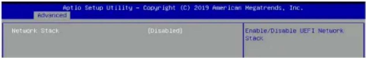
Network Stack
Allows you to enable or disable UEFI Network Stack.
Configuration options: [Disabled] [Enabled]
NOTE: The following items appear only when Network Stack is set to [Enabled].
Ipv4 PXE Support
Enables or disables the lpv4 PXE Boot Support. If disabled, lpv4 PXE boot option will not be created.
Configuration options: [Disabled] [Enabled]
Ipv6 PXE Support
Enables or disables the lpv6 PXE Boot Support. If disabled, lpv6 PXE boot option will not be created.
Configuration options: [Disabled] [Enabled]
4.4.15 SDIO Configuration
![Optio Setup Utility - Copyright (C) 2019 American Megatrends, Inc. Advanced SDIO Configuration SDIO Access Mode [Auto] Auto Option: Access SD device in DMA mode if controller supports it,otherwise in PIO mode.DMA Option: Access SD device in DMA mode.PIO Option: Access SD device in PIO mode.](/content/2026/06/1175753/images/758fb5fbe13b6217884c054eaf55c4954246823a71dd50a8a57cec947017f39f.jpg)
SDIO Access Mode
[Auto] Access SD device in DMA mode if controller supports it, otherwise access SD device in PIO mode.
[ADMA] Access SD device in ADMA mode.
[SDMA] Access SD device in SDMA mode.
[PIO] Access SD device in PIO mode.
4.4.16 Platform Trust Technology
![Aptio Setup Utility - Copyright (C) 2019 American Megatrends, Inc. Advanced TPM Configuration TPM Device Selection [Firmware TPM] Selects TPM device: Firmware TPM or Discrete TPM. Firmware TPM - Enables PTT in SkuMgr. Discrete TPM - Disables PTT in SkuMgr. Harning I](/content/2026/06/1175753/images/94d0a77bcfc045f598c44c735ef18f430ca566899102b9c1cf4e0a77c392c148.jpg)
TPM Device Selection
Allows you to select the TPM device.
[Firmware TPM] Enables PTT in SkuMgr.
[Discrete TPM] Disables PTT in SkuMgr.
WARNING! Selecting [Discrete TPM] will disable PTT and Discrete TPM, and all data saved on it will be lost.
4.4.17 Security Configuration
![Aptio Setup Utility - Copyright (C) 2019 American Megatrends, Inc. Advanced TXE HHRFPO [Disabled] TXE EOP Message [Enabled] Enable/Disable TXE HHRFPO](/content/2026/06/1175753/images/319ec62cfc4608d916e1db106ed2cf438b091c092a1119f452811e73b0098b06.jpg)
TXE HMRFPO
Allows you to enable or disable TXE HMRFPO.
Configuration options: [Disabled] [Enabled]
TXE EOP Message
Allows you to enable or disable sending EOP Message before entering OS.
Configuration options: [Disabled] [Enabled]
4.4.18 LFP Configuration

IGD Flat Panel
Allows you to enable or disable IGD video output to onboard LVDS.
Configuration options: [Disable] [Enable]
NOTE: The following items appear only when IGD Flat Panel is set to [Enable].
LVDS Output Channel Select
Allows you to select the LVDS output channel.
Configuration options: [Single Channel] [Dual Channel]
LVDS Output Format and Color Depth
Allows you to select the LVDS data format and color depth.
Configuration options: [VESA 24 bpp] [JEDIA 24 bpp] [VESA and JEDIA 18 bpp]
EDID Data Source
Allows you to select the EDID data source.
Configuration options: [Pre-defined] [Flat Panel Display]
4.4.19 Thermal
| Aptio Setup Utility - Copyright (C) 2019 American Megatrends, Inc. Advanced | |
| Thermal Configuration Parameters Automatic Thermal Reporting [Disabled] Critical Trip Point [125 C] Passive Trip Point [111 C] Active Trip Point [60 C] | Configure _CRT, _PSV and _ACO automatically based on values recommended in BWG's Thermal Reporting for Thermal Management settings. Set to Disabled for manual configuration. |
Automatic Thermal Reporting
Allows you to configure _CRT, _PSV, and _ACO automatically based on values recommended in BWG's Thermal Reporting for Thermal Management settings. Set to [Disabled] for manual configuration.
Configuration options: [Disabled] [Enabled]
NOTE: The following items appear only when Automatic Thermal Reporting is set to [Disabled].
Critical Trip Point
This value controls the temperature of the ACPI Critical Trip Point - the point in which the OS will shut the system off.
Configuration options: [15 C] [23 C] [31 C] [39 C] [47 C] [55 C] [63 C] [71 C] [79 C] [87 C] [95 C] [100 C] [103 C] [110 C] [119 C] [125 C]
Passive Trip Point
This value controls the temperature of the ACPI Passive Trip Point - the point in which the OS will begin throttling the processor.
Configuration options: [95 C] [Disabled [15 C] [23 C] [31 C] [39 C] [47 C]
[55 C] [63 C] [71 C] [79 C] [87 C] [103 C] [111 C]
Active Trip Point
This value controls the temperature of the ACPI Active Trip Point - the point in which the OS will turn the fan on.
Configuration options: [15 C] [23 C] [31 C] [39 C] [47 C] [55 C] [60 C] [63 C] [71 C] [79 C] [87 C] [95 C] [103 C] [110 C]
4.5 Security
This menu allows a new password to be created or a current password to be changed. The menu also enables or disables the Secure Boot state and lets the user configure the System Mode state.
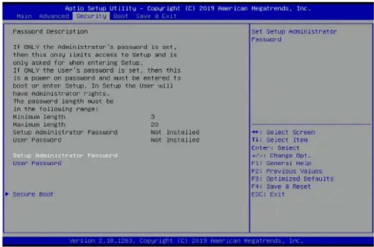
Administrator Password
To set an administrator password:
- Select the Administrator Password item and press
. - From the Create New Password box, key in a password, then press
. - Confirm the password when prompted.
To change an administrator password:
- Select the Administrator Password item and press
. - From the Enter Current Password box, key in the current password, then press
. - From the Create New Password box, key in a new password, then press
. - Confirm the password when prompted.
NOTE: To clear the administrator password, follow the same steps as in changing an administrator password, but press
User Password
To set a user password:
- Select the User Password item and press
. - From the Create New Password box, key in a password, then press
. - Confirm the password when prompted.
To change a user password:
- Select the User Password item and press
. - From the Enter Current Password box, key in the current password, then press
. - From the Create New Password box, key in a new password, then press
. - Confirm the password when prompted.
To clear a user password:
- Select the Clear User Password item and press
. - Select Yes from the Warning message window then press
.
Secure Boot
Secure Boot can be enabled if the system is running in User mode with enrolled platform Key (EPK) or if the CSM function is disabled.
Configuration options: [Disabled] [Enabled]
Key Management
The Key Management item allows you to modify Secure Boot variables and set Key Management page.
Force System to User Mode. Configure NVRAM to contain OEM-defined factory default Secure Boot keys.
Reset to Setup Mode
Delete NVRAM content of all UEFI Secure Boot key databases.
Export Secure Boot Variables
Copy NVRAM content of source Boot variables to files in a root folder on a file system device.
Platform Key (PK)
Configuration options: [Details] [Export] [Update] [Delete]
Key Exchange Keys / Authorized Signatures / Forbidden Signatures
Configuration options: [Details] [Export] [Update] [Append] [Delete]
4.6 Boot menu
The Boot menu items allow you to change the system boot options.
![Aptio Setup Utility - Copyright (C) 2019 American Megatrends, Inc. Main Advanced Security Boot Save & Exit Boot Configuration Fast Boot [Enable] SATA Support [All SATA Devices] VGA Support [EFI Driver] USB Support [Partial Initial] Network Stack Driver Support [Disable] Redirection Support [Disable] CSM Configuration Setup Prompt Timeout 1 Bootup NumLock State [On] Chassis Intrusion Detection [Disabled] POST Delay Time [3 sec] Hait For 'F1' If Error [Enabled] Quiet Boot [Enabled] Boot Option Priorities Boot Option #1 [Windows Boot Manager (P0: TS128GSSD420I)] Boot Override Windows Boot Manager (P0: TS128GSSD420I) Enable or Disable FastBoot features. Most probes are skipped to reduce time cost during boot. +: Select Screen T↓: Select Item Enter: Select +/-: Change Opt. F1: General Help F2: Previous Values F3: Optimized Defaults F4: Save & Reset ESC: Exit Version 2.18.1263. Copyright (C) 2019 American Megatrends, Inc.](/content/2026/06/1175753/images/952fcb3f2277712cfeab03d75e4f95a425d5befcf4ccabe86d18e7234817919d.jpg)
Fast Boot
[Disabled] Allows your system to go back to its normal boot speed.
[Enabled] Allows your system to accelerate the boot speed.
NOTE: The following items appear only when Fast Boot is set to [Enabled].
SATA Support
[Last Boot SATA Devices Only] Only last boot SATA device will be available in POST.
[All SATA Devices] All SATA devices will be available in OS and POST.
VGA Support
[Auto] Only install the Legacy OpRom with Legacy OS and logo will not be shown during POST.
[EFI Driver] EFI driver will still be installed with the EFI OS.
USB Support
[Disabled] All USB devices will NOT be available until after OS boot.
[Full Initial] All USB devices will be available in OS and POST.
[Partial Initial] USB Mass Storage and specific USB port/device will NOT be available before OS boot.
Network Stack Driver Support
[Disabled] Network Stack Driver will be skipped.
[Enabled] Network Stack Driver will not be skipped.
Redirection Support
Allows you to enable or disable the Redirection function.
Configuration options: [Disabled] [Enabled]
CSM Configuration
NOTE: The options in this menu are only available if Secure Boot is set to [Disabled].
CSM Support
This option allows you to enable or disable CSM Support.
Configuration options: [Disabled] [Enabled]
NOTE: The following items appear only when CSM Support is set to [Enabled].
Boot Option filter
This option allows you to control the Legacy/UEFI ROMs priority. Configuration options: [UEFI and Legacy] [Legacy only] [UEFI only]
Network / Storage / Video
This option allows you to control the execution of UEFI and Legacy PXE/ Storage/ Video OpROM.
Configuration options: [Do not launch] [UEFI] [Legacy]
Other PCI devices
This item determines the OpROM execution policy for devices other than Network, Storage, or Video.
Configuration options: [Do not launch] [UEFI] [Legacy]
Setup Prompt Timeout
Allows you to set the number of seconds to wait for setup activation key. 65535(0xFFFF) means indefinite waiting.
Configuration options: [1] - [65535]
Setup Prompt Timeout
Allows you to set the number of seconds to wait for setup activation key. 65535(0xFFFF) means indefinite waiting.
Configuration options: [1] - [65535]
Boot up NumLock State
[On] Set the power-on state of the NumLock to [On].
[Off] Set the power-on state of the NumLock to [Off].
Chassis Intrusion Detection
Allows you to enable or disable the chassis intrusion detection function. Configuration options: [Disabled] [Enabled]
Post Delay Time
Allows you to select a desired additional POST waiting time to easily enter the BIOS Setup. You can only execute the POST delay time during normal boot. The values range from 0 to 10 seconds.
NOTE: This feature only works when set under normal boot.
Wait For 'F1' If Error
Enable this item for the system to pause until the F1 key is pressed when any error occurs.
Configuration options: [Disabled] [Enabled]
Quiet Boot
Allows you to enable or disable the Quiet Boot option.
Configuration options: [Disabled] [Enabled]
Boot Option Priorities
These items specify the boot device priority sequence from the available devices. The number of device items that appears on the screen depends on the number of devices installed in the system.
NOTE:
- To access Windows® OS in Safe Mode, press
after POST (Windows® 8 not supported). - To select the boot device during system startup, press
when the ASUS Logo appears.
Boot Override
These items displays the available devices. The number of device items that appears on the screen depends on the number of devices installed in the system. Click an item to start booting from the selected device.
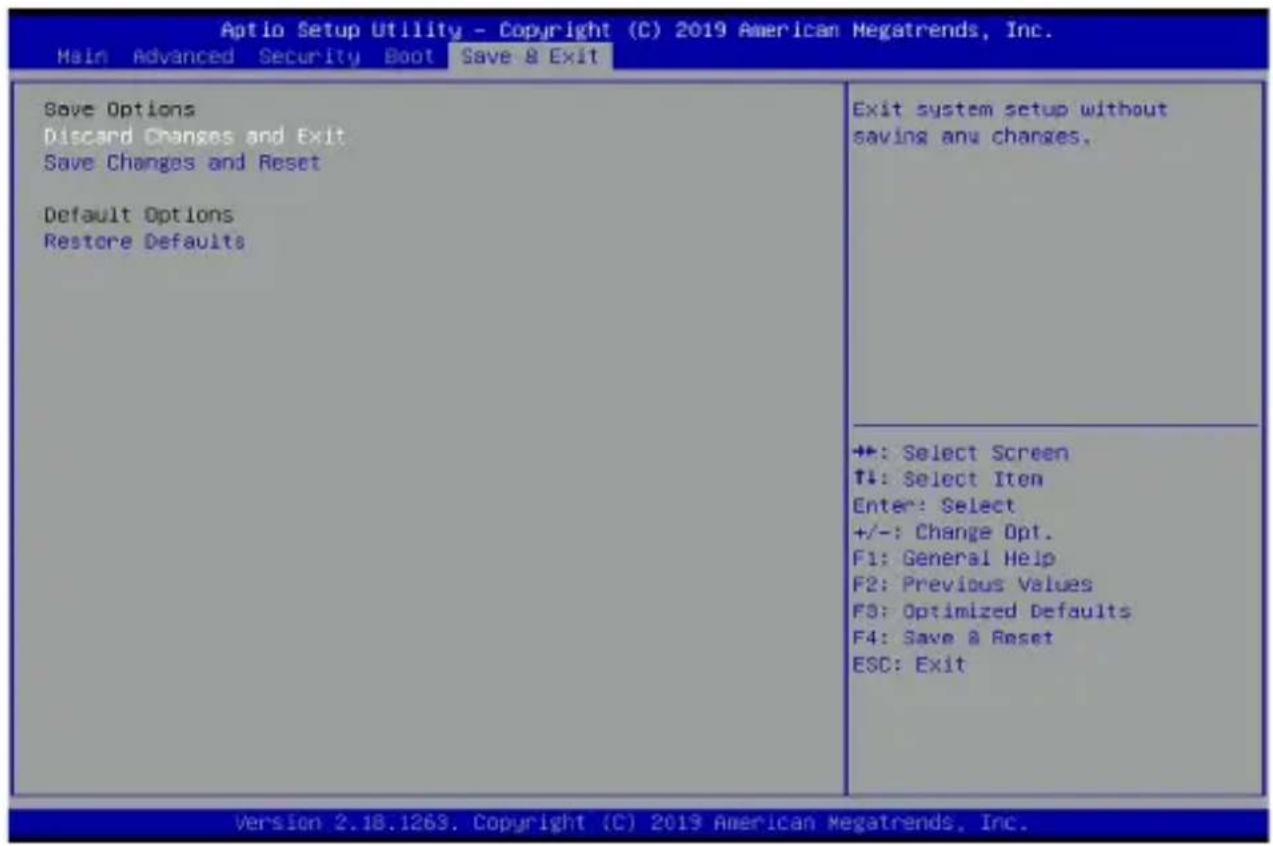
4.7 Save & Exit menu
The Save & Exit menu items allow you to save or discard your changes to the BIOS items.
NOTE: Pressing
Discard Changes and Exit
Exit System setup without saving any changes.
Save Changes and Reset
Exit System setup after saving the changes.
Restore Defaults
Restore/load default values for all the setup options.
4.8 Updating your BIOS
The following utilities allow you to manage and update the motherboard Basic Input/Output System (BIOS) setup:
1. ASUS CrashFree BIOS 3
To recover the BIOS using a bootable USB flash disk drive when the BIOS file fails or gets corrupted.
2. ASUS EzFlash
Updates the BIOS using a USB flash disk.
3. BUPDATER
Updates the BIOS in DOS mode using a bootable USB flash disk drive. Refer to the corresponding sections for details on these utilities.
IMPORTANT! Save a copy of the original motherboard BIOS file to a bootable USB flash disk drive in case you need to restore the BIOS in the future. Copy the original motherboard BIOS using the BUPDATER utility.
4.8.1 ASUS CrashFree BIOS 3 utility
The ASUS CrashFree BIOS 3 is an auto recovery tool that allows you to restore the BIOS file when it fails or gets corrupted during the updating process. You can update a corrupted BIOS file using a USB flash drive that contains the updated BIOS file.
IMPORTANT! Prepare a USB flash drive containing the updated motherboard BIOS before using this utility.
Recovering the BIOS from a USB flash drive
To recover the BIOS from a USB flash drive:
-
Insert the USB flash drive with the original or updated BIOS file to one USB port on the system.
-
The utility will automatically recover the BIOS. It resets the system when the BIOS recovery finished.
WARNING! DO NOT shut down or reset the system while recovering the BIOS! Doing so would cause system boot failure!
NOTE: The recovered BIOS may not be the latest BIOS version for this motherboard. Visit the ASUS website at www.asus.com to download the latest BIOS file.
4.8.2 ASUS EzFlash Utility
The ASUS EzFlash Utility feature allows you to update the BIOS using a USB flash disk without having to use a DOS-based utility.
IMPORTANT! Download the latest BIOS from the ASUS website at www.asus.com before using this utility.
NOTE: The succeeding BIOS screens are for reference only. The actual BIOS screen displays may not be the same as shown.
To update the BIOS using EzFlash Utility:
-
Insert the USB flash disk that contains the latest BIOS file to the USB port.
-
Enter the BIOS setup program. Go to the Advanced menu to select Start ASUS EzFlash and press
to enable it.
WARNING! Ensure to back up your Bitlocker recovery key and suspend Bitlocker encryption in the operating system before updating your BIOS.
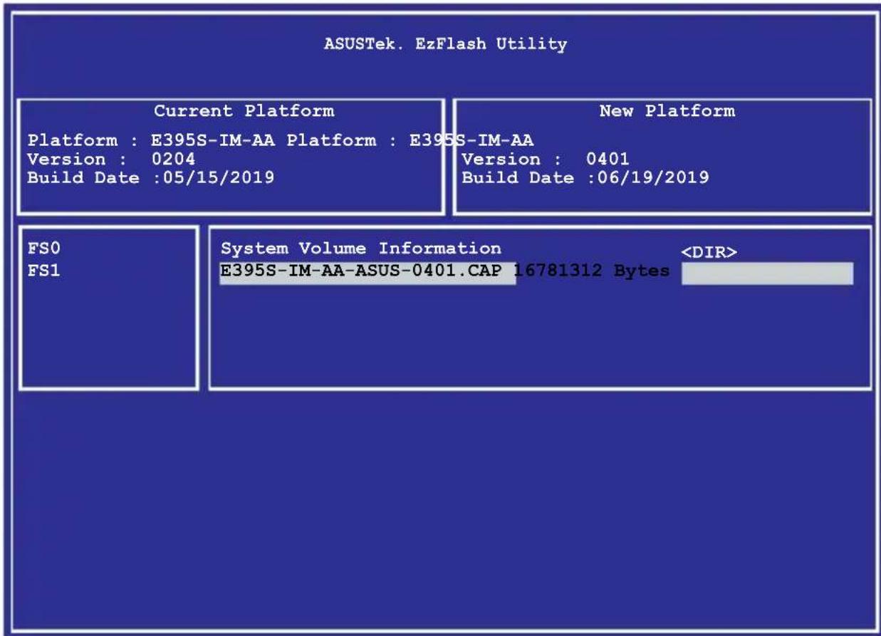
- Press
to switch to the Drive field. - Press the Up/Down arrow keys to find the USB flash disk that contains the latest BIOS then press
. - Press
to switch to the Folder Info field. - Press the Up/Down arrow keys to find the BIOS file then press
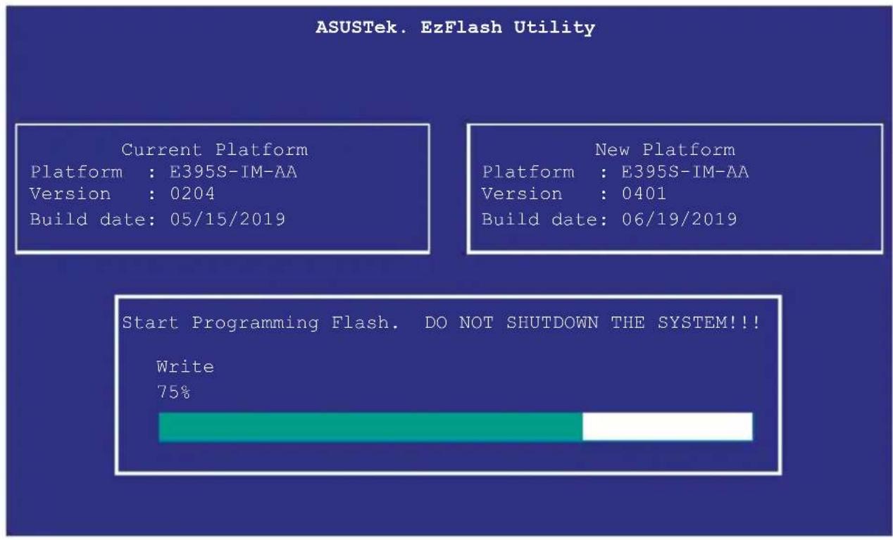
. - Reboot the system when the update process is done.
WARNING
- This function can support devices such as a USB flash disk with FAT 32/16 format and single partition only.
- DO NOT shut down or reset the system while updating the BIOS to prevent system boot failure!
IMPORTANT! Ensure to load the BIOS default settings to ensure system compatibility and stability. Press
4.8.3 BUPDATER utility
NOTE: The succeeding BIOS screens are for reference only. The actual BIOS screen displays may not be the same as shown.
The BUPDATER utility allows you to update the BIOS file in DOS environment using a bootable USB flash disk drive with the updated BIOS file.
Updating the BIOS file
To update the BIOS file using the BUPDATER utility:
- Visit the ASUS website at www.asus.com and download the latest BIOS file for the motherboard. Save the BIOS file to a bootable USB flash disk drive.
-
Download the BUPDATER utility (BUPDATER.exe) from the ASUS support website at support.asus.com to the bootable USB flash disk drive you created earlier.
-
Boot the system in DOS mode, then at the prompt, type:
BUPDATER /i[filename].CAP
where [filename] is the latest or the original BIOS file on the bootable USB flash disk drive, then press
A:>BUPDATER /i [file name]CAP
- The utility verifies the file, then starts updating the BIOS file.
WARNING! DO NOT shut down or reset the system while updating the BIOS to prevent system boot failure!
- The utility returns to the DOS prompt after the BIOS update process is completed. Reboot the system from the hard disk drive.
The BIOS update is finished! Please restart your system. C:>
Appendix
Safety information
Your Single Board Computer is designed and tested to meet the latest standards of safety for information technology equipment. However, to ensure your safety, it is important that you read the following safety instructions.
Setting up your system
- Read and follow all instructions in the documentation before you operate your system.
- Do not use this product near water or a heated source.
- Set up the system on a stable surface.
- Peripherals with extended temperature tolerance (such as industrial grade DRAM, SSD, etc.) will allow this product to be used in environments with ambient temperatures between -20°C and 60°C, with a 0.1m/s air flow. If you plan to use a 2.5" HDD with this product, please use this product in environments with ambient temperatures between 0°C\~45°C, with a 0.1m/s air flow.
- The product should be used in environments with an ambient temperature of 45^ C when using the 65W adapter, whilst using HDD or SDD only and without the PoE module installed.
- If you use an extension cord, make sure that the total ampere rating of the devices plugged into the extension cord does not exceed its ampere rating.
- This equipment should be installed and operated with a minimum distance of 20cm between the radiator and your body.
- Restricted Access Location:
The equipment should only be installed in a Restricted Access Area where both these conditions apply: - access can only be gained by USERS who have been instructed about the reasons for the restrictions applied to the location and about any precautions that shall be taken; and
- access is through the use of a TOOL or lock and key, or other means of security, and is controlled by the authority responsible for the location.
- This device shall not be connected to an Ethernet network with outside plant routing.
Care during use
- Do not walk on the power cord or allow anything to rest on it.
- Do not spill water or any other liquids on your system.
- When the system is turned off, a small amount of electrical current still flows. Always unplug the power cord from the power outlets before cleaning the system.
- If you encounter the following technical problems with the product, unplug the power cord and contact a qualified service technician or your retailer.
- The power cord or plug is damaged.
- Liquid has been spilled into the system.
- The system does not function properly even if you follow the operating instructions.
- The system was dropped or the cabinet is damaged.
- The system performance changes.
Lithium-Ion Battery Warning
CAUTION: Danger of explosion if battery is incorrectly replaced. Replace only with the same or equivalent type recommended by the manufacturer. Dispose of used batteries according to the manufacturer's instructions.
NO DISASSEMBLY
The warranty does not apply to the products that have been disassembled by users

DO NOT throw the Single Board Computer in municipal waste. This product has been designed to enable proper reuse of parts and recycling. This symbol of the crossed out wheeled bin indicates that the product (electrical, electronic equipment, and mercury-containing button cell battery) should not be placed in municipal waste. Check local technical support services for product recycling.
Safety precautions
Accessories that came with this product have been designed and verified for the use in connection with this product. Never use accessories for other products to prevent the risk of electric shock or fire.
Regulatory notices
REACH
Complying with the REACH (Registration, Evaluation, Authorization, and Restriction of Chemicals) regulatory framework, we publish the chemical substances in our products at ASUS REACH website at http://csr.asus.com/english/REACH.htm
ASUS Recycling/Takeback Services
ASUS recycling and takeback programs come from our commitment to the highest standards for protecting our environment. We believe in providing solutions for you to be able to responsibly recycle our products, batteries, other components, as well as the packaging materials. Please go to http://csr.asus.com/english/Takeback.htm for the detailed recycling information in different regions.
COATING NOTICE
IMPORTANT! To provide electrical insulation and maintain electrical safety, a coating is applied to insulate the device except on the areas where the I/O ports are located.
RF exposure warning
This equipment must be installed and operated in accordance with provided instructions and the antenna(s) used for this transmitter must be installed to provide a separation distance of at least 20 cm from all persons and must not be co-located or operating in conjunction with any other antenna or transmitter. End-users and installers must be provide with antenna installation instructions and transmitter operating conditions for satisfying RF exposure compliance.
Federal Communications Commission Statement
This device complies with Part 15 of the FCC Rules. Operation is subject to the following two conditions:
- This device may not cause harmful interference, and
- This device must accept any interference received including interference that may cause undesired operation.
This equipment has been tested and found to comply with the limits for a Class A digital device, pursuant to part 15 of the FCC Rules. These limits are designed to provide reasonable protection against harmful interference when the equipment is operated in a commercial environment.
This equipment generates, uses, and can radiate radio frequency energy and, if not installed and used in accordance with the instruction manual, may cause harmful interference to radio communications. Operation of this equipment in a residential area is likely to cause harmful interference in which case the user will be required to correct the interference at his own expense.
IMPORTANT! Outdoor operations in the 5.15\~5.25 GHz band is prohibited. This device has no Ad-hoc capability for 5250\~5350 and 5470\~5725 MHz.
CAUTION! Any changes or modifications not expressly approved by the grantee of this device could void the user's authority to operate the equipment.
ISED Radiation Exposure Statement for Canada
This equipment complies with ISED radiation exposure limits set forth for an uncontrolled environment. To maintain compliance with ISED RF exposure compliance requirements, please avoid direct contact to the transmitting antenna during transmitting. End users must follow the specific operating instructions for satisfying RF exposure compliance.
Operation is subject to the following two conditions:
• This device may not cause interference and
- This device must accept any interference, including interference that may cause undesired operation of the device.
Compliance Statement of Innovation, Science and Economic Development Canada (ISED)
This device complies with Innovation, Science and Economic Development Canada licence exempt RSS standard(s). Operation is subject to the following two conditions: (1) this device may not cause interference, and (2) this device must accept any interference, including interference that may cause undesired operation of the device.
CAN ICES-003(A)/NMB-003(A)
Wireless Operation Channel for Different Domains
N. America 2.412-2.462 GHz Ch01 through CH11
Japan 2.412-2.484 GHz Ch01 through Ch14
Europe ETSI 2.412-2.472 GHz Ch01 through Ch13
Regional notice for Singapore
Complies with IMDA Standards DB103778
This ASUS product complies with IMDA Standards.
Regional notice for California
WARNING! This product contains chemicals known to the State of California to cause cancer, and birth defects or other reproductive harm. Wash hands after handling.
Regional notice for Malaysia

HDMI Trademark Notice
The terms HDMI, HDMI High-Definition Multimedia Interface, and the HDMI Logo are trademarks or registered trademarks of HDMI Licensing Administrator, Inc.
ENERGY STAR complied product
ENERGY STAR is a joint program of the U.S. Environmental Protection

Agency and the U.S. Department of Energy helping us all save money and protect the environment through energy efficient products and practices.
All ASUS products with the ENERGY STAR logo comply with the ENERGY STAR standard, and the power management feature is enabled by default. The monitor and computer are automatically set to sleep after 10 and 30 minutes of user inactivity. To
wake your computer, click the mouse or press any key on the keyboard.
Please visit http://www.energystar.gov/powermanagement for detail information on power management and its benefits to the environment. In addition, please visit http://www.energystar.gov for detail information on the ENERGY STAR joint program.
NOTE: Energy Star is NOT supported on FreeDOS and Linux-based products.
Service and Support
Visit our multi-language website at https://www.asus.com/support.

| Manufacturer ASUSTek COMPUTER INC. | |
| Address, City 1F., No. 15, Lide | Rd., Beitou Dist., Taipei City 112 |
| Authorized Representative in Europe | ASUS COMPUTER GmbH |
| Address Harkortstrasse 21-23, | 40880 Ratingen |
| Country Germany | |
| Authorized Representative in United Kingdom | ASUSTEK (UK) LIMITED |
| Address 1st Floor, Sackville House, 143-149 Fenchurch Street, London, EC3M 6BL, England | |
| Country United Kingdom | |