AP130-D5 - Uncategorized ASUS - Free user manual and instructions
Find the device manual for free AP130-D5 ASUS in PDF.

| Product Type | Rackmount Server |
| Model | AP130-D5 |
| Form Factor | 1U Rackmount |
| Dimensions (W x D x H) | 444 x 535 x 43.4 mm |
| Weight | Approximately 12 kg |
| Power Supply | Dual redundant 800W PSU |
| Processor | Intel Xeon Scalable Gen 3 |
| Memory | DDR4-3200, up to 512 GB |
| Storage | Up to 8 x 3.5" SAS/SATA hot-swap bays |
| Network | 2 x 10GbE LAN ports |
| Management | ASUS ASMB9-iKVM remote management |
| Cooling | 4 x hot-swap system fans |
| Expansion Slots | 2 x PCIe 4.0 x16 FHHL slots |
| Operating Temperature | 10°C to 35°C |
| Input Voltage | 100-240 VAC, 50/60 Hz |
| Certifications | CE, FCC, RoHS |
| Maintenance | Tool-less access to internal components |
| Safety Features | Over-temperature, over-current protection |
| Spare Parts Availability | PSU, fans, HDD trays available from ASUS |
| User Manual Pages | 128 pages |
Frequently Asked Questions - AP130-D5 ASUS
User questions about AP130-D5 ASUS
0 question about this device. Answer the ones you know or ask your own.
Ask a new question about this device
Download the instructions for your Uncategorized in PDF format for free! Find your manual AP130-D5 - ASUS and take your electronic device back in hand. On this page are published all the documents necessary for the use of your device. AP130-D5 by ASUS.
USER MANUAL AP130-D5 ASUS
Copyright © 2002 ASUSTeK COMPUTER INC. All Rights Reserved.
No part of this manual, including the products and software described in it, may be reproduced, transmitted, transcribed, stored in a retrieval system, or translated into any language in any form or by any means, except documentation kept by the purchaser for backup purposes, without the express written permission of ASUSTeK COMPUTER INC. ("ASUS").
Product warranty or service will not be extended if: (1) the product is repaired, modified or altered, unless such repair, modification of alteration is authorized in writing by ASUS; or (2) the serial number of the product is defaced or missing.
ASUS PROVIDES THIS MANUAL "AS IS" WITHOUT WARRANTY OF ANY KIND, EITHER EXPRESS OR IMPLIED, INCLUDING BUT NOT LIMITED TO THE IMPLIED WARRANTIES OR CONDITIONS OF MERCHANTABILITY OR FITNESS FOR A PARTICULAR PURPOSE. IN NO EVENT SHALL ASUS, ITS DIRECTORS, OFFICERS, EMPLOYEES OR AGENTS BE LIABLE FOR ANY INDIRECT, SPECIAL, INCIDENTAL, OR CONSEQUENTIAL DAMAGES (INCLUDING DAMAGES FOR LOSS OF PROFITS, LOSS OF BUSINESS, LOSS OF USE OR DATA, INTERRUPTION OF BUSINESS AND THE LIKE), EVEN IF ASUS HAS BEEN ADVISED OF THE POSSIBILITY OF SUCH DAMAGES ARISING FROM ANY DEFECT OR ERROR IN THIS MANUAL OR PRODUCT.
SPECIFICATIONS AND INFORMATION CONTAINED IN THIS MANUAL ARE FURNISHED FOR INFORMATIONAL USE ONLY, AND ARE SUBJECT TO CHANGE AT ANY TIME WITHOUT NOTICE, AND SHOULD NOT BE CONSTRUED AS A COMMITMENT BY ASUS. ASUS ASSUMES NO RESPONSIBILITY OR LIABILITY FOR ANY ERRORS OR INACCURACIES THAT MAY APPEAR IN THIS MANUAL, INCLUDING THE PRODUCTS AND SOFTWARE DESCRIBED IN IT.
Products and corporate names appearing in this manual may or may not be registered trademarks or copyrights of their respective companies, and are used only for identification or explanation and to the owners' benefit, without intent to infringe.
Contents
Contents .... iii
FCC/CDC statements...... vi
Safety information ...... vii
About this guide...... viii
How this guide is organized ...... viii
Conventions used in this guide ix
Where to find more information ix
ASUS contact information ....X
P4B533-M specifications summary ...... xi
Chapter 1: Product introduction
1.1 Welcome! 1-1
1.2 Package contents 1-1
1.3 Special features.... 1-2
1.3.1 Product highlights 1-2
1.3.2 Value-added solutions.... 1-3
1.4 Motherboard overview 1-4
1.4.1 Major components 1-4
1.4.2 Core specifications 1-6
Chapter 2: Hardware information
2.1 Motherboard installation 2-1
2.1.1 Placement direction 2-1
2.1.2 Screw holes 2-1
2.2 Motherboard layout 2-2
2.3 Before you proceed 2-3
2.4 Central Processing Unit (CPU).... 2-4
2.4.1 Overview 2-4
2.4.2 Installing the CPU 2-5
2.4.3 Installing the heatsink and fan 2-7
2.4.4 Connecting the CPU fan cable 2-9
2.5 System memory 2-10
2.5.1 Overview 2-10
2.5.2 Memory configurations .....2-11
2.5.3 Installing a DIMM 2-11
2.5.4 Removing a DIMM 2-12
Contents
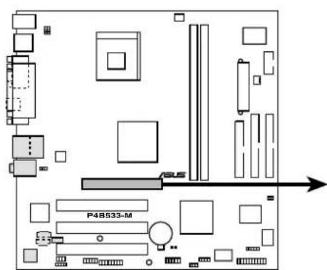
2.6 Expansion slots 2-13
2.6.1 Installing an expansion card 2-13
2.6.2 Configuring an expansion card 2-13
2.6.3 PCI slots 2-15
2.6.4 AGP slot 2-15
2.7 Switches and jumpers 2-16
2.8 Connectors 2-20
Chapter 3: Powering up
3.1 Starting up for the first time 3-1
3.2 Powering off the computer 3-2
Chapter 4: BIOS setup
4.1 Managing and updating your BIOS 4-1
4.1.1 Using ASUS EZ Flash to update the BIOS 4-1
4.1.2 Using AFLASH to update the BIOS 4-3
4.2 BIOS Setup program 4-7
4.2.1 BIOS menu bar 4-8
4.2.2 Legend bar.... 4-8
4.3 Main Menu.... 4-10
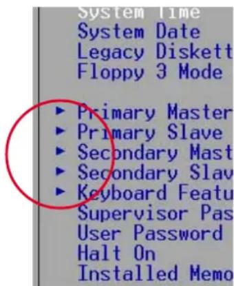
4.3.1 Primary and Secondary Master/Slave 4-12
4.3.2 Keyboard Features 4-16
4.4 Advanced Menu 4-17
4.4.1 Chip Configuration 4-19
4.4.2 I/O Device Configuration.... 4-22
4.4.3 PCI Configuration 4-24
4.5 Power Menu 4-27
4.5.1 Power Up Control 4-29
4.5.2 Hardware Monitor 4-31
4.6 Boot Menu 4-32
4.7 Exit Menu 4-34
Contents
Chapter 5: Software support
5.1 Install an operating system.... 5-1
5.2 Support CD information 5-1
5.2.1 Running the support CD 5-1
5.2.2 Main menu 5-2
5.2.3 Software menu.... 5-3
5.2.4 Drivers menu 5-5
5.2.5 DOS Utility menu 5-6
5.2.6 ASUS Contact Information.... 5-6
5.2.7 Other information 5-7
5.3 Software information 5-9
5.3.1 ASUS Update 5-9
5.3.2 ASUS PC Probe ....5-11
5.3.3 E-Color 3Deep 5-16
Glossary G-1
Index I-1
FCC/CDC statements
Federal Communications Commission Statement
This device complies with FCC Rules Part 15. Operation is subject to the following two conditions:
- This device may not cause harmful interference, and
- This device must accept any interference received including interference that may cause undesired operation.
This equipment has been tested and found to comply with the limits for a Class B digital device, pursuant to Part 15 of the FCC Rules. These limits are designed to provide reasonable protection against harmful interference in a residential installation. This equipment generates, uses and can radiate radio frequency energy and, if not installed and used in accordance with manufacturer's instructions, may cause harmful interference to radio communications. However, there is no guarantee that interference will not occur in a particular installation. If this equipment does cause harmful interference to radio or television reception, which can be determined by turning the equipment off and on, the user is encouraged to try to correct the interference by one or more of the following measures:
- Reorient or relocate the receiving antenna.
- Increase the separation between the equipment and receiver.
- Connect the equipment to an outlet on a circuit different from that to which the receiver is connected.
- Consult the dealer or an experienced radio/TV technician for help.

The use of shielded cables for connection of the monitor to the graphics card is required to assure compliance with FCC regulations. Changes or modifications to this unit not expressly approved by the party responsible for compliance could void the user's authority to operate this equipment.
Canadian Department of Communications Statement
This digital apparatus does not exceed the Class B limits for radio noise emissions from digital apparatus set out in the Radio Interference Regulations of the Canadian Department of Communications.
This class B digital apparatus complies with Canadian ICES-003.
Safety information
Electrical safety
- To prevent electrical shock hazard, disconnect the power cable from the electrical outlet before relocating the system.
- When adding or removing devices to or from the system, ensure that the power cables for the devices are unplugged before the signal cables are connected. If possible, disconnect all power cables from the existing system before you add a device.
- Before connecting or removing signal cables from the motherboard, ensure that all power cables are unplugged.
- Seek professional assistance before using an adapter or extension cord. These devices could interrupt the grounding circuit.
- Make sure that your power supply is set to the correct voltage in your area. If you are not sure about the voltage of the electrical outlet you are using, contact your local power company.
- If the power supply is broken, do not try to fix it by yourself. Contact a qualified service technician or your retailer.
Operation safety
- Before installing the motherboard and adding devices on it, carefully read all the manuals that came with the package.
- Before using the product, make sure all cables are correctly connected and the power cables are not damaged. If you detect any damage, contact your dealer immediately.
- To avoid short circuits, keep paper clips, screws, and staples away from connectors, slots, sockets and circuitry.
- Avoid dust, humidity, and temperature extremes. Do not place the product in any area where it may become wet.
- Place the product on a stable surface.
- If you encounter technical problems with the product, contact a qualified service technician or your retailer.
About this guide
This user guide contains the information you need when installing the ASUS P4B533-M motherboard.
How this guide is organized
This manual contains the following parts:
• Chapter 1: Product introduction
This chapter describes the features of the P4B533-M motherboard. It includes brief descriptions of the special attributes of the motherboard and the new technology it supports.
• Chapter 2: Hardware information
This chapter lists the hardware setup procedures that you have to perform when installing system components. It includes description of the switches, jumpers, and connectors on the motherboard.
• Chapter 3: Powering up
This chapter describes the power up sequence and gives information on the BIOS beep codes.
• Chapter 4: BIOS setup
This chapter tells how to change system settings through the BIOS Setup menus. Detailed descriptions of the BIOS parameters are also provided.
• Chapter 5: Software support
This chapter describes the contents of the support CD that comes with the motherboard package.
- Glossary
This part defines the technical terms that you may encounter when reading this document.
- Index
This part contains an alphabetical list of the topics found in this document.
Conventions used in this guide
To make sure that you perform certain tasks properly, take note of the following symbols used throughout this manual.

WARNING: Information to prevent injury to yourself when trying to complete a task.

CAUTION: Information to prevent damage to the components when trying to complete a task.

IMPORTANT: Information that you MUST follow to complete a task.

NOTE: Tips and additional information to aid in completing a task.
Where to find more information
Refer to the following sources for additional information and for product and software updates.
1. ASUS Websites
The ASUS websites worldwide provide updated information on ASUS hardware and software products. The ASUS websites are listed in the ASUS Contact Information on page x.
2. Optional Documentation
Your product package may include optional documentation, such as warranty flyers, that may have been added by your dealer. These documents are not part of the standard package.
ASUS contact information
ASUSTeK COMPUTER INC. (Asia-Pacific)
Address: 150 Li-Te Road, Peitou, Taipei, Taiwan 112
General Tel: +886-2-2894-3447
General Fax: +886-2-2894-3449
Address: 6737 Mowry Avenue, Mowry Business Center, Building 2, Newark, CA 94560, USA
General Fax: +1-510-608-4555
General Email: tmd1@asus.com
Technical Support
Support Fax: +1-510-608-4555
General Support: +1-502-995-0883
Notebook Support: +1-877-918-ASUS (2787)
Web Site: www.asus.com
Support Email: tsd@asus.com
ASUS COMPUTER GmbH (Europe)
Address: Harkortstr. 25, 40880 Ratingen, BRD, Germany
General Fax: +49-2102-442066
General Email: sales@asuscom.de (for marketing requests only)
Technical Support
Support Hotline: MB/Others: +49-2102-9599-0
Notebook (Tel): +49-2102-9599-10
Support Fax: +49-2102-9599-11
Support (Email): www.asuscom.de/de/support (for online support)
Web Site: www.asuscom.de
P4B533-M specifications summary
| CPU | Socket 478 for Intel® Pentium® 4On-die 512KB/256KB L2 cache |
| Chipset | Intel 82845E MCHIntel 82801 DB ICH4 |
| Front Side Bus (FSB) | 533/400 MHz |
| Memory | 2 x 184-pin DDR DIMM sockets for up to 2GB memorySupports PC2100/1600 unbuffered ECC/non-ECC DDR DIMMs |
| Expansion slots | 1 x AGP 4X (1.5V only)3 x PCI |
| IDE | 2 x UltraDMA 100/66/33 |
| Audio (optional) | C-Media CMI9738 4-channel audio CODEC |
| Special features | ASUS EZ FlashPower Loss RestartAGP warning LED |
| Rear panel I/O | 1 x Parallel port1 x Serial port1 x PS/2 keyboard port1 x PS/2 mouse port4 x USB 2.0/USB 1.1 ports1 x IEEE-1394 port (optional)1 x RJ-45 port (optional)Line In/Line Out/Microphone ports (optional) |
| Internal I/O | 1 x USB 2.0/1.1 connector for 2 additional USB portsCPU/Chassis fan connectors20-pin/4-pin ATX power connectorsIDE LED/Power LED connectorsChassis intrusion and SIR connectorsGAME/MIDI connector (optional)CD/AUX audio connectors (optional)Front panel audio connector (optional) |
| BIOS features | 2Mb Flash ROM, Award BIOS, TCAV, PnP, DMI2.0, WfM2.0, SM BIOS2.3, ASUS EZ Flash |
| Industry standard | PCI 2.2, USB 2.0 |
| Manageability | WfM 2.0. DMI 2.0, chassis intrusion |
(continued on the next page)
P4B533-M specifications summary
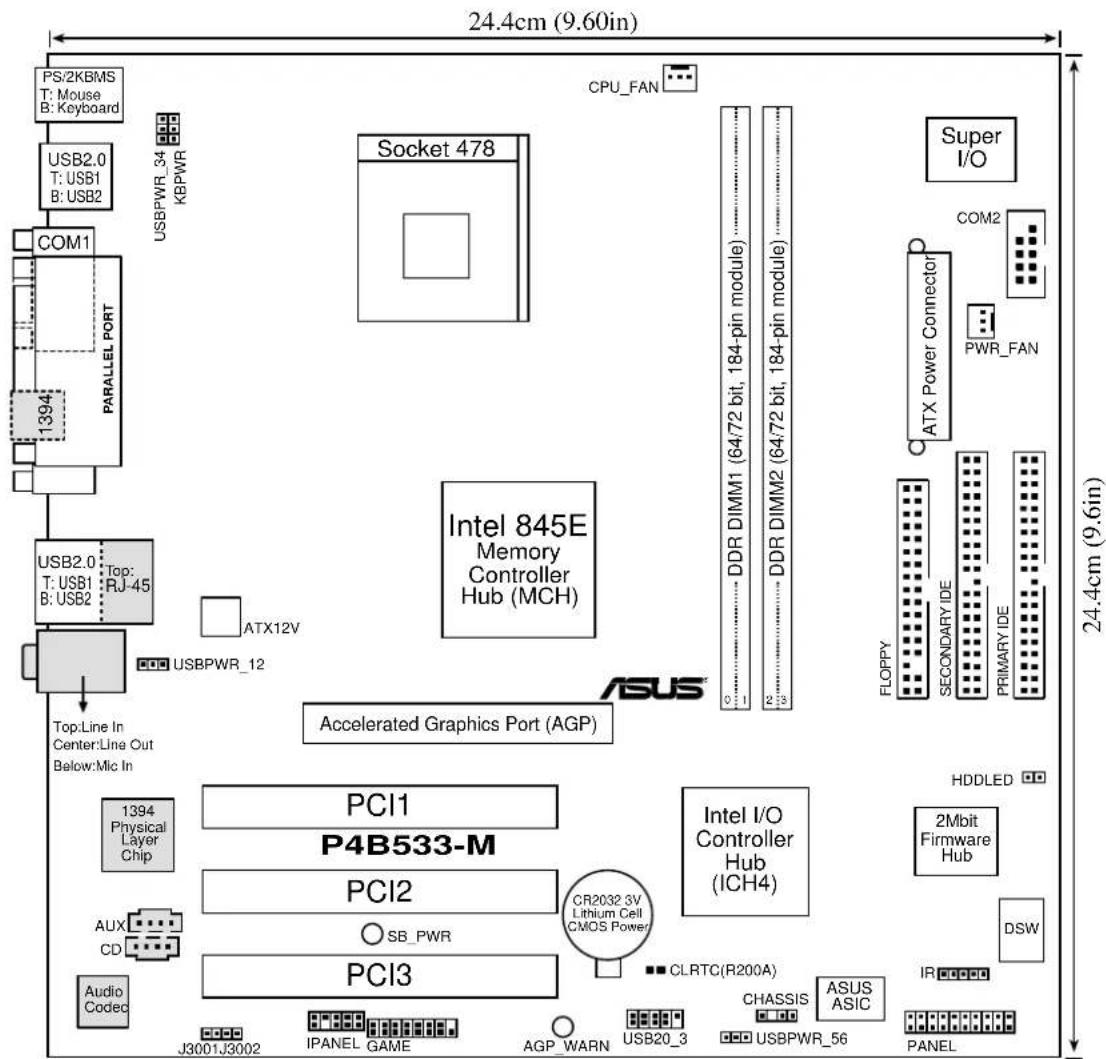
| Form Factor | Micro-ATX form factor: 9.6 in x 9.6 in (24.5 cm x 24.5 cm) |
| Support CD contents | Device driversASUS PC ProbeASUS LiveUpdateTrend MicroTM PC-cillin 2002 anti-virus softwareCyberLink Power Player SE, VideoLive Mail |
* Specifications are subject to change without notice.
Chapter 1
This chapter describes the features of the P4B533-M motherboard. It includes brief explanations of the special attributes of the motherboard and the new technology it supports.
Product introduction
Chapter summary
1.1 Welcome! 1-1
1.2 Package contents 1-1
1.3 Special features 1-2
1.4 Motherboard overview.... 1-4
1.1 Welcome!
Thank you for buying the ASUS® P4B533-M motherboard!
The ASUS P4B533-M motherboard delivers a host of new features and latest technologies making it another standout in the long line of ASUS quality motherboards!
The P4B533-M incorporates the Intel® Pentium® 4 Processor in 478-pin package coupled with the Intel® 845E (Brookdale-E) chipset to deliver a high performance desktop platform solution.
Supporting up to 2GB of system memory with PC2100/1600 DDR SDRAM, high-resolution graphics via an AGP 4X slot, USB 2.0 capability, high-speed data transfers using the ATA100 protocol, and 4-channel audio features, the P4B533-M is your perfect vehicle to get ahead in the world of power computing!
Before you start installing the motherboard, and hardware devices on it, check the items in your package with the list below.
1.2 Package contents
Check your P4B533-M package for the following items.
√ ASUS P4B533-M motherboard
micro-ATX form factor: 9.6 in x 9.6 in (24.5 cm x 24.5 cm)
√ ASUS P4B533-M series support CD
√ ASUS USB 2.0/GAME module
√ 80-conductor ribbon cable for UltraDMA/100/66/33 IDE drives
√ Ribbon cable for a 3.5-inch floppy drive
√ Bag of extra jumper caps
√ User Guide

If any of the above items is damaged or missing, contact your retailer.
1.3 Special features
1.3.1 Product highlights
Latest processor technology
The P4B533-M motherboard supports the latest Intel® Pentium® 4 Processor via a 478-pin surface mount ZIF socket. The Pentium 4 processor with 512KB L2 cache on 0.13 micron process features the Intel® NetBurst™ micro-architecture that includes hyper-pipelined technology, a rapid execution engine, a 533MHz system bus, and an execution trace cache to offer a significant increase in performance. See page 2-4 for more information.
DDR memory support
Employing the Double Data Rate (DDR) memory technology, the P4B533-M motherboard supports up to 2GB of system memory using PC2100/1600 DDR DIMMs. The ultra-fast 266MHz memory bus doubles the speed of the PC133 SDRAM to deliver the required bandwidth for the latest 3D graphics, multimedia, and Internet applications. See page 2-10.
USB 2.0 technology
The motherboard implements the new Universal Serial Bus (USB) 2.0 specification, extending the connection speed from 12 Mbps on USB 1.1 to a fast 480 Mbps on USB 2.0. The higher bandwidth of USB 2.0 allows connection of devices such as high resolution video conferencing cameras, next generation scanners and printers, and fast storage units. USB 2.0 is backward compatible with USB 1.1. See page 2-24.
NOTICE: The Microsoft USB 2.0 driver has not been officially released as of the support CD production date. Please download the USB 2.0 driver from the Microsoft website (www.microsoft.com) to upgrade your USB 1.1 ports to USB 2.0.
IEEE-1394 feature (on 1394 models only)
The TSB43AB21 controller and a 1394 port are onboard to support up to 400Mbps data transfers.
4-channel digital audio (on audio models only)
A C-Media CMI9738 audio CODEC is onboard to support AC '97 2.2 specifications. This feature allows 4-channel audio connections ideal for PC'99-compliant home entertainment PCs.
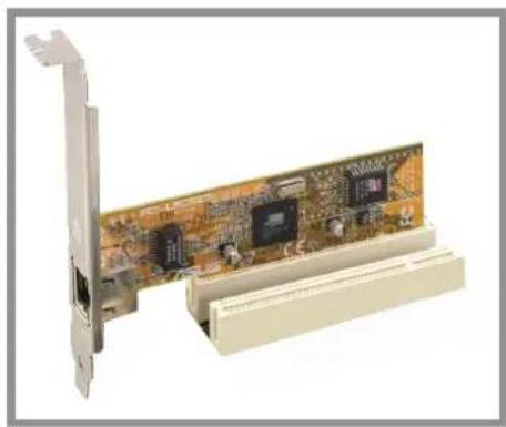
Onboard LAN (on LAN models only)
The motherboard supports 10BASE-T/100BASE-TX networking via the onboard Intel 82562ET LAN PHY that connects to the south bridge (ICH4).
1.3.2 Value-added solutions
Concurrent PCI
This feature allows multiple PCI transfers from PCI master buses to the memory and processor.
Temperature, fan, and voltage monitoring
The CPU temperature is monitored by the ASUS ASIC through the CPU's internal diode to prevent overheating and damage. The system fan rotations per minute (RPM) is monitored for timely failure detection. The system voltage levels are monitored to ensure stable supply of current for critical components.
Dual function power switch
While the system is ON, pressing the power switch for less than 4 seconds puts the system to sleep mode or to soft-off mode, depending on the BIOS setting. Pressing the power switch for more than 4 seconds lets the system enter the soft-off mode regardless of the BIOS setting.
ACPI ready
The Advanced Configuration power Interface (ACPI) provides more energy saving features for operating systems that support OS Direct Power Management (OSPM).
Auto fan off
The system fans power off automatically when the system is in sleep mode. This feature reduces both power consumption and system noise.
Chassis intrusion detection
The motherboard supports chassis intrusion monitoring through the ASUS ASIC. A chassis intrusion event is retained in the system memory for more protection.
1.4 Motherboard overview
Before you install the P4B533-M motherboard, familiarize yourself with its physical configuration and available features to facilitate the motherboard installation and future upgrades. A sufficient knowledge of the motherboard specifications will also help you avoid mistakes that may damage the board and its components.
1.4.1 Major components
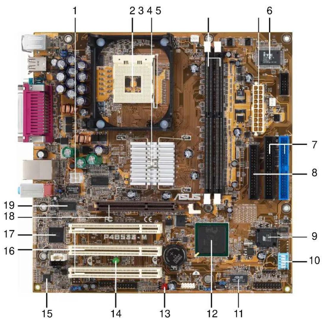
The following are the major components of the P4B533-M motherboard as pointed out in the picture on page 1-5.
- ATX 12V connector
- CPU socket
- North Bridge controller
- DDR DIMM sockets
- ATX power connector
- Super I/O controller
- IDE connectors
- Floppy connector
- Flash EEPROM
- DIP swtiches
-
ASUS ASIC
-
South Bridge controller
-
AGP warning LED
-
Standby power LED
-
Audio CODEC (optional)
-
PCI slots
-
1394 controller (optional)
-
AGP slot
-
LAN PHY (optional)

See page 1-6 for the specifications of each component. Refer to Chapter 2 for detailed information on the components.
1.4.2 Core specifications
1 ATX 12V connector. This power connector is for the 4-pin 12V plug from an ATX 12V power supply.
2 CPU socket. A 478-pin surface mount, Zero Insertion Force (ZIF) socket for the Intel® Pentium® 4 Processor, with 533/400MHz system bus that allows 4.3GB/s and 3.2GB/s data transfer rates.
3 North bridge controller. The Intel® 845E Memory Controller Hub (MCH) provides the processor interface with 533/400MHz frequency, system memory interface at 133/100MHz operation, and 1.5V AGP interface that supports AGP 2.0 specification including 2X/4X Fast Write protocol. The MCH interconnects to the south bridge ICH4 via the Intel® proprietary Hub Interface.
4 DDR DIMM sockets. These two 184-pin DIMM sockets support up to 2GB using unbuffered ECC or non-ECC PC2100/1600 DDR DIMMs.
5 ATX power connector. This 20-pin connector connects to an ATX +12V power supply. The power supply must have at least 1A on the +5V standby lead (+5VSB).
6 Super I/O controller. This Low Pin Count (LPC) interface provides the commonly used Super I/O functionality. The chipset supports a high-performance floppy disk controller for a 360K/720K/1.44M/2.88M floppy disk drive, a multi-mode parallel port, two standard compatible UARTs, a Standard Infrared (SIR), one MPU-401 UART mode compatible MIDI/game interface, and a Flash ROM interface.
7 IDE connectors. These dual-channel bus master IDE connectors support up to four Ultra DMA/100/66, PIO Modes 3 & 4 IDE devices. Both the primary (blue) and secondary (black) connectors are slotted to prevent incorrect insertion of the IDE ribbon cable.
8 Floppy disk connector. This connector accommodates the provided ribbon cable for the floppy disk drive. One side of the connector is slotted to prevent incorrect insertion of the floppy disk cable.
9 Flash EEPROM. This 2Mb firmware contains the programmable BIOS program.
10 DIP switches. This 5-switch Dual Inline Package (DIP) allows you to set the CPU external frequency.
11 ASUS ASIC. This chip performs multiple system functions that include hardware and system voltage monitoring.
12 South bridge controller. The fourth-generation Intel I/O Controller Hub (ICH4) is a subsystem that integrates various I/O functions including 2-channel ATA/100 bus master IDE controller, up to six USB 2.0/1.1 ports, I/O APIC, SMBus 2.0 controller, LPC interface, AC'97 2.2 interface, PCI 2.2 interface, and integrated LAN controller. The ICH4 also contains the necessary arbitration and buffering for efficient utilization of these interfaces.
13 AGP warning LED. Serving as a smart burn-out protection for the motherboard, this red LED lights up if you plug in any 3.3V AGP card into the AGP slot. When this LED is lit, there is no way you can turn on the system power even if you press the power button.
14 Standby power LED. This green LED lights up if there is a standby power on the motherboard. The LED acts as a reminder to turn off the system power before plugging or unplugging devices.
15 Audio CODEC. The C-Media CMI9738 is an AC'97 2.1 compliant audio CODEC designed for PC multimedia systems. (on audio models only)
16 PCI slots. These three 32-bit PCI 2.2 expansion slots support bus master PCI cards with 133MB/s maximum throughput.
17 1394 controller. The TSB43AB21 is an integrated 1394a-2000 controller that is fully compliant with 1394 Open Host Controller Interface (OHCI) specification 1.1. This device allows data transfers between the 33MHz PCI bus and the 1394 bus at 100Mbps, 200Mbps, and 400Mbps through a 1394 port. It also provides PCI bus master bursting, and is capable of transferring a cacheline data at 132MB/s to support digital electronic devices. The TSB43AB21 is fully interoperable with FireWire and i.LINK implementations of IEEE Std 1394. (on 1394 models only)
18 AGP slot. This Accelerated Graphics Port (AGP) slot supports 1.5V AGP4X mode graphics cards for 3D graphical applications.
19 LAN PHY. This Intel 82562ET LAN PHY works with the integrated MAC in the South Bridge (ICH4) to fully support 10BASE-T/100BASE-TX Ethernet networking. (on LAN models only)
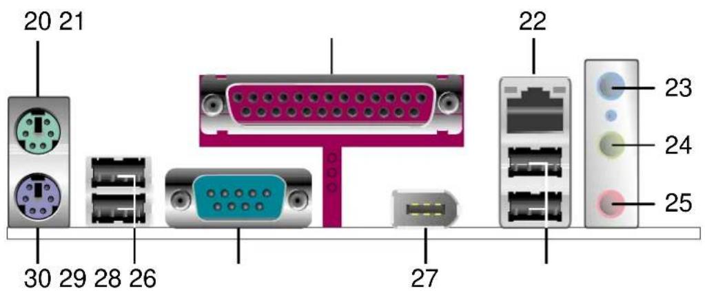
20 PS/2 mouse port. This green 6-pin connector is for a PS/2 mouse.
21 Parallel port. This 25-pin port connects a parallel printer, a scanner, or other devices.
22 RJ-45 port. This port allows connection to a Local Area Network (LAN) through a network hub. (on LAN models only)
23 Line In jack. This Line In (light blue) jack connects a tape player or other audio sources. In 4-channel mode, the function of this jack becomes Rear Speaker Out. (on audio models only)
24 Line Out jack. This Line Out (lime) jack connects a headphone or a speaker. In 4-channel mode, the function of this jack becomes Rear Speaker Out. (on audio models only)
25 Microphone jack. This Mic (pink) jack connects a microphone. In 4-channel mode, the function of this jack becomes Bass/Center. (on audio models only)
26 USB 2.0 ports 1 and 2. These two 4-pin Universal Serial Bus (USB) ports are available for connecting USB 2.0 devices.
27 IEEE-1394 port. This 6-pin digital interface supports electronic devices such as DV camcorders, digital cameras, scanners, and printers. (on 1394 models only)
28 Serial port. This 9-pin COM1 port is for pointing devices or other serial devices.
29 USB 2.0 ports 3 and 4. These two 4-pin Universal Serial Bus (USB) ports are available for connecting USB 2.0 devices.
30 PS/2 keyboard port. This purple 6-pin connector is for a PS/2 keyboard.
Chapter 2
This chapter describes the hardware setup procedures that you have to perform when installing system components. It includes details on the switches, jumpers, and connectors on the motherboard.
Hardware information
Chapter summary
2.1 Motherboard installation 2-1
2.2 Motherboard layout 2-2
2.3 Before you proceed 2-3
2.4 Central Processing Unit (CPU) 2-4
2.5 System memory 2-10
2.6 Expansion slots 2-13
2.7 Switches and jumpers 2-16
2.8 Connectors 2-20
2.1 Motherboard installation
Before you install the motherboard, study the configuration of your chassis to ensure that the motherboard fits into it. The P4B533-M uses the micro-ATX form factor that measures 9.6 in x 9.6 in (24.5 cm x 24.5 cm).

Make sure to unplug the power cord before installing or removing the motherboard. Failure to do so may cause you physical injury and damage motherboard components.
2.1.1 Placement direction
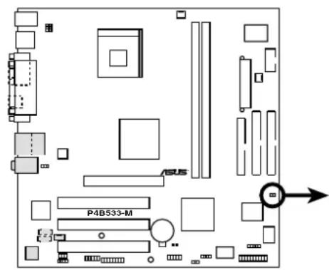
When installing the motherboard, make sure that you place it into the chassis in the correct orientation. The edge with external ports goes to the rear part of the chassis as indicated in the image below.
2.1.2 Screw holes
Place eight (8) screws into the holes indicated by circles to secure the motherboard to the chassis.

Do not overtighten the screws! Doing so may damage the motherboard.
Place this side towards the rear of the chassis
natural_image
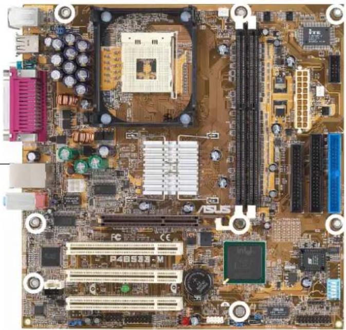
Close-up of a computer motherboard with CPU socket, RAM slots, and various electronic components (no readable text or symbols)2.2 Motherboard layout

The audio, LAN, and 1394 features are optional. These components are grayed out in the above motherboard layout.
2.3 Before you proceed
Take note of the following precautions before you install motherboard components or change any motherboard settings.

- Unplug the power cord from the wall socket before touching any component.
- Use a grounded wrist strap or touch a safely grounded object or to a metal object, such as the power supply case, before handling components to avoid damaging them due to static electricity.
- Hold components by the edges to avoid touching the ICs on them.
- Whenever you uninstall any component, place it on a grounded antistatic pad or in the bag that came with the component.
- Before you install or remove any component, ensure that the ATX power supply is switched off or the power cord is detached from the power supply. Failure to do so may cause severe damage to the motherboard, peripherals, and/or components.

When lit, the green LED (SB_PWR) indicates that the system is ON, in sleep mode, or in soft-off mode, a reminder that you should shut down the system before removing or plugging in any motherboard component.
The red LED (AGP_WARN) is a smart protection from motherboard burn out caused by an incorrect AGP card. If you plug in any 3.3V AGP card into the 1.5V AGP slot, this LED lights up thus preventing the system to power up. This LED remains off if you plug in a 1.5V AGP card.
P4B533-M Onboard LED

2.4 Central Processing Unit (CPU)
2.4.1 Overview
The motherboard comes with a surface mount 478-pin Zero Insertion Force (ZIF) socket. The socket is designed for the Intel Pentium 4 Processor in the 478-pin package with 512KB L2 cache on 0.13 micron process. This processor includes the Intel® NetBurst™ micro-architecture that features the hyper-pipelined technology, rapid execution engine, 533/400MHz system bus, and execution trace cache. Together, these attributes improve system performance by allowing higher core frequencies, faster execution of integer instructions, and data transfer rates of 4.2 GB/s and 3.2GB/s.
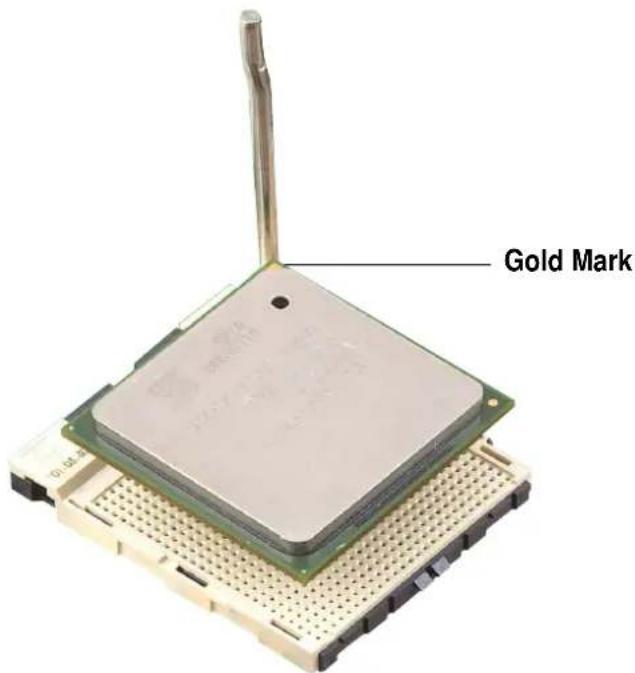
Note in the illustration that the CPU has a gold triangular mark on one corner. This mark indicates the processor Pin 1 that should match a specific corner of the CPU socket.

Incorrect installation of the CPU into the socket may bend the pins and severely damage the CPU!
2.4.2 Installing the CPU
Follow these steps to install a CPU.
- Locate the 478-pin ZIF socket on the motherboard.
natural_image
Close-up of a computer motherboard with an inset close-up showing the internal circuit board (no text or symbols visible)- Unlock the socket by pressing the lever sideways, then lift it up to a 90^-100^ angle.
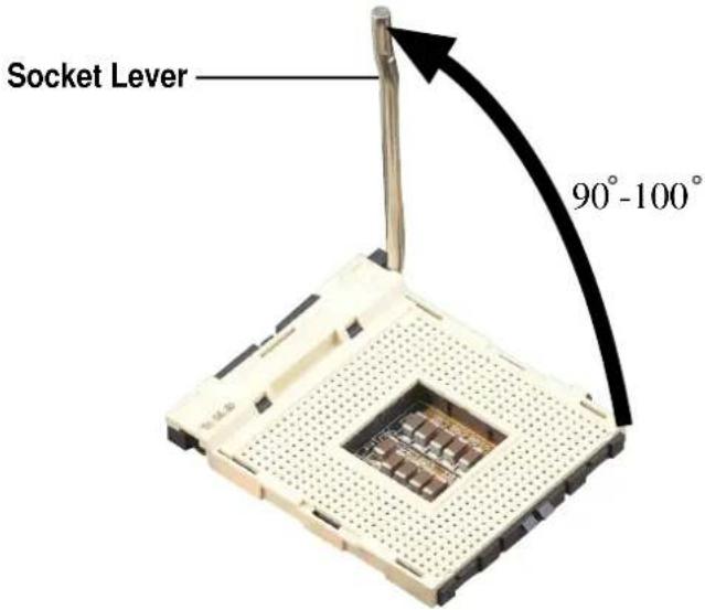

Make sure that the socket lever is lifted up to 90^-100^ angle, otherwise the CPU does not fit in completely.
-
Position the CPU above the socket such that its marked corner matches the base of the socket lever.
-
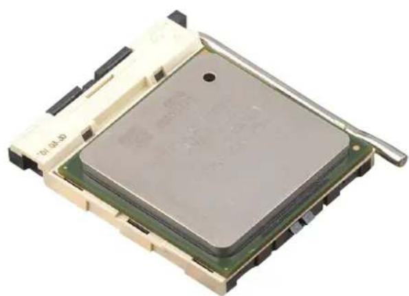
Carefully insert the CPU into the socket until it fits in place.

The CPU fits only in one correct orientation. DO NOT force the CPU into the socket to prevent bending the pins and damaging the CPU!
- When the CPU is in place, press it firmly on the socket while you push down the socket lever to secure the CPU. The lever clicks on the side tab to indicate that it is locked.
natural_image
Close-up of a microprocessor chip with visible cooling fins and a metallic handle (no text or symbols)2.4.3 Installing the heatsink and fan
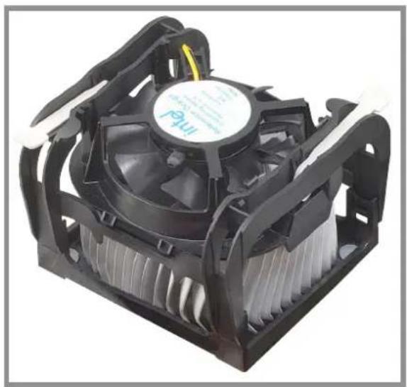
The Intel® Pentium® 4 Processor requires a specially designed heatsink and fan assembly to ensure optimum thermal condition and performance.

When you buy a boxed Intel Pentium 4 Processor, the package includes the heatsink, fan, and retention mechanism.
In case you buy a CPU separately, make sure that you use only Intel certified heatsink and fan.
Follow these steps to install the CPU heatsink and fan.
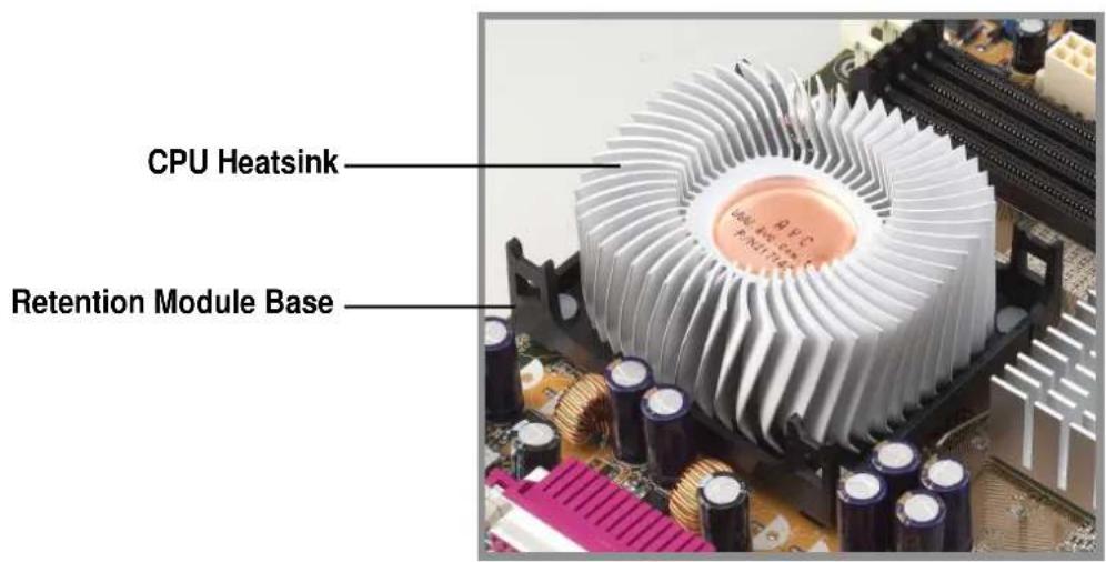
- Place the heatsink on top of the installed CPU, making sure that the heatsink fits properly on the retention module base.

The retention module base is already installed on the motherboard upon purchase.
You do not have to remove the retention module base when installing the CPU or installing other motherboard components.

Your boxed Intel Pentium 4 Processor package should come with installation instructions for the CPU, heatsink, and the retention mechanism. If the instructions in this section do not match the CPU documentation, follow the latter.
- Position the fan with the retention mechanism on top of the heatsink. Align and snap the four hooks of the retention mechanism to the holes on each corner of the module base.

Make sure that the fan and retention mechanism assembly perfectly fits the heatsink and module base, otherwise you cannot snap the hooks into the holes.
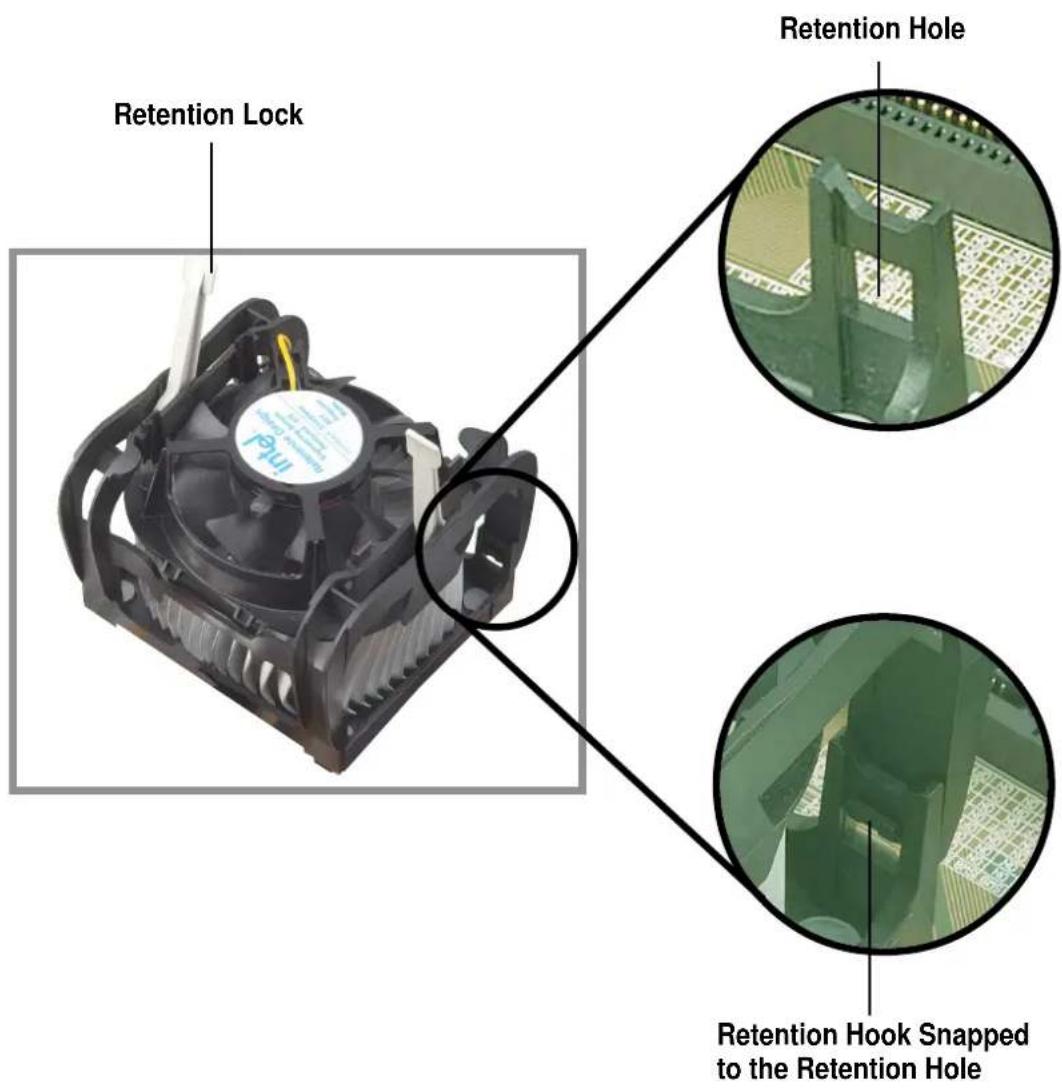

Keep the retention locks lifted upward while fitting the retention mechanism to the module base.
- Push down the locks on the retention mechanism to secure the heatsink and fan to the module base.

When secure, the retention locks should point to opposite directions.
natural_image
Close-up of a black CPU fan with cooling fins and heatsink (no visible text or symbols)2.4.4 Connecting the CPU fan cable
When the fan, heatsink, and the retention mechanism are in place, connect the CPU fan cable to the connector on the motherboard labeled CPU_FAN.
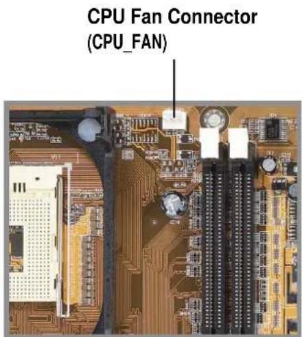

Don't forget to connect the CPU fan connector! Hardware monitoring errors may occur if you fail to plug this connector.
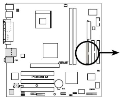
2.5 System memory
2.5.1 Overview
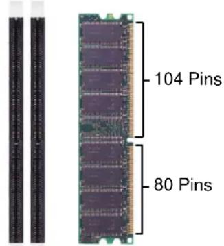
The motherboard comes with two Double Data Rate (DDR) Dual Inline Memory Module (DIMM) sockets. These sockets support up to 2GB system memory using 184-pin unbuffered ECC or non-ECC PC2100/1600 DIMMs.
P4B533-M 184-Pin DDR DIMM Sockets

A DDR DIMM is keyed with a notch so that it fits in only one direction. DO NOT force a DIMM into a socket to avoid damaging the DIMM.
The DDR SDRAM technology evolved from the mainstream PC66, PC100, PC133 memory known as Single Data Rate (SDR) SDRAM. DDR memory however, has the ability to perform two data operations in one clock cycle, thus providing twice the throughput of SDR memory. For example, a 200MHz DDR DIMM will support a 100MHz memory bus, and a 266MHz DDR DIMM will support a 133MHz memory bus.
| DDR Data Transfer Rate DDR Base Frequency | |
| 266MHz 133MHz | → |
| 200MHz 100MHz | → |
A DDR DIMM has the same physical dimensions as an SDR DIMM, but it has a 184-pin footprint compared to the 168-pin of the SDR DIMM. Also, a DDR DIMM is single notched while an SDR DIMM is double notched. Therefore, a DDR DIMM is not backward compatible with SDR, and should be installed only in a socket specially designed for DDR DIMMs.
2.5.2 Memory configurations
You may install any DDR DIMMs with 64MB, 128MB, 256MB, 512MB, and 1GB densities into the DIMM sockets.
DIMM Location 184-pin DDR DIMM Total Memory
| Socket 1 (Rows 0&1) 64MB, 128MB, 256MB, 512MB, 1GB x1 = |
| Socket 2 (Rows 2&3) 64MB, 128MB, 256MB, 512MB, 1GB x1 = |
Total system memory (Max. 2GB) =
2.5.3 Installing a DIMM

Make sure to unplug the power supply before adding or removing DIMMs or other system components. Failure to do so may cause severe damage to both the motherboard and the components.
Follow these steps to install a DIMM.
- Unlock a DIMM socket by pressing the retaining clips outward.
- Align a DIMM on the socket such that the notch on the DIMM matches the break on the socket.
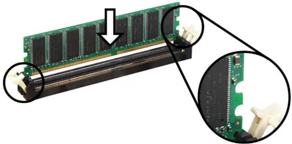
natural_image
Close-up of a green RAM module with attached connectors and a close-up view showing internal components (no text or symbols visible)Unlocked Retaining Clip
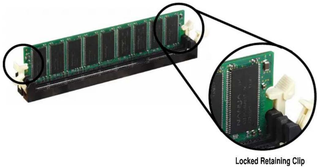
- Firmly insert the DIMM into the socket until the retaining clips snap back in place and the DIMM is properly seated.
natural_image
Close-up of a green RAM module with attached pin connectors, showing internal structure and close-up of its locked retaining clip (no text or symbols on the chip itself)2.5.4 Removing a DIMM
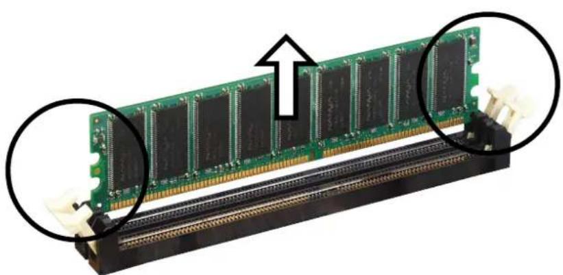
Follow these steps to remove a DIMM.
- Simultaneously press the retaining clips outward to unlock the DIMM.

Support the DIMM lightly with your fingers when pressing the retaining clips. The DIMM might get damaged when it flips out with extra force.
- Remove the DIMM from the socket.
natural_image
Close-up of a green RAM module with black connectors and a close-up view showing internal structure (no text or symbols visible)2.6 Expansion slots
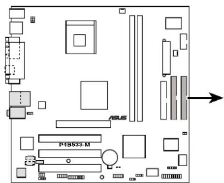
In the future, you may need to install expansion cards. The motherboard has three PCI slots and one Accelerated Graphics Port (AGP) slot. The following sub-sections describe the slots and the expansion cards that they support.

Make sure to unplug the power cord before adding or removing expansion cards. Failure to do so may cause you physical injury and damage motherboard components.
2.6.1 Installing an expansion card
Follow these steps to install an expansion card.
- Before installing the expansion card, read the documentation that came with it and make the necessary hardware settings for the card.
- Remove the system unit cover (if your motherboard is already installed in a chassis).
- Remove the bracket opposite the slot that you intend to use. Keep the screw for later use.
- Align the card connector with the slot and press firmly until the card is completely seated on the slot.
- Secure the card to the chassis with the screw you removed earlier.
- Replace the system cover.
2.6.2 Configuring an expansion card
After installing the expansion card, configure the it by adjusting the software settings.
-
Turn on the system and change the necessary BIOS settings, if any. See Chapter 4 for information on BIOS setup.
-
Assign an IRQ to the card. Refer to the tables on the next page.
-
Install the software drivers for the expansion card.
Standard Interrupt Assignments
IRQ Priority Standard Function
| 0 1 System Timer |
| 1 2 Keyboard Controller |
| 2 N/A Programmable Interrupt |
| 3* 11 Communications Port (COM2) |
| 4* 12 Communications Port (COM1) |
| 5* 13 Sound Card (sometimes LPT2) |
| 6 14 Floppy Disk Controller |
| 7* 15 Printer Port (LPT1) |
| 8 3 System CMOS/Real Time Clock |
| 9* 4 ACPI Mode when used |
| 10* 5 IRQ Holder for PCI Steering |
| 11* 6 IRQ Holder for PCI Steering |
| 12* 7 PS/2 Compatible Mouse Port |
| 13 8 Numeric Data Processor |
| 14* 9 Primary IDE Channel |
| 15* 10 Secondary IDE Channel |
* These IRQs are usually available for ISA or PCI devices.
IRQ assignments for this motherboard
When using PCI cards on shared slots, ensure that the drivers support "Share IRQ" or that the cards do not need IRQ assignments.
Otherwise, conflicts will arise between the two PCI groups, making the system unstable and the card inoperable.
2.6.3 PCI slots
There are three 32-bit PCI slots in this motherboard. The slots support PCI cards such as a LAN card, SCSI card, USB card, and other cards that comply with PCI specifications. The following figure shows a LAN card installed on a PCI slot.
natural_image
Close-up of a PCI expansion card showing circuit board, ports, and connectors (no text or symbols visible)2.6.4 AGP slot
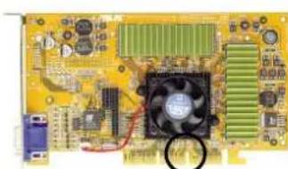
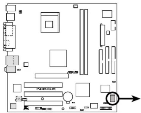
This motherboard has an Accelerated Graphics Port (AGP) slot that supports +1.5V AGP cards. When you buy an AGP card, make sure that you ask for one with +1.5V specification. Note the notches on the card golden fingers to ensure that they fit the AGP slot on your motherboard.
If you installed an incorrect AGP card, such as a SiS305-based AGP card or any other 3.3V AGP card, the onboard red LED (AGP_WARN) lights up, an indication that the card is not supported on the motherboard. As long as this LED is lighted, you cannot turn on the system power even if you press the power button, thus preventing permanent damage to the motherboard.

Install only 1.5V AGP cards on this motherboard!
natural_image
Close-up of a yellow computer motherboard with CPU socket, heatsink, and connectors (no visible text or symbols)Keyed for 1.5V
P4B533-M Accelerated Graphics Port (AGP)
2.7 Switches and jumpers
The motherboard frequency is adjusted through the DIP switches. The white block represents the switch position. The illustration below shows the ON and OFF positions of the switches.
P4B533-M DIP Switches
DSW

- Frequency Selection
2.Frequency Selection
3.Frequency Selection
4.Frequency Selection
5.Frequency Selection
1. CPU frequency selection (DSW Switches 1-5)
This option tells the clock generator what frequency to send the CPU, and to the AGP and PCI slots. This allows the selection of the CPU's external frequency (or Bus Clock).
P4B533-M CPU
External Frequency Selection
DSW
CPU
100MHz
105MHz
109MHz
133MHz
CPU 135MHz
139MHz
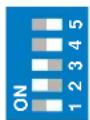
145MHz

Set the CPU frequency only to the recommended settings.
Frequencies other than the recommended CPU bus frequencies are not guaranteed to be stable.
2. Keyboard power (3-pin KBPWR)
This jumper allows you to enable or disable the keyboard wake-up feature. Set this jumper to pins 2-3 (+5VSB) if you wish to wake up the computer when you press a key on the keyboard. This feature requires an ATX power supply that can supply at least 1A on the +5VSB lead, and a corresponding setting in the BIOS.
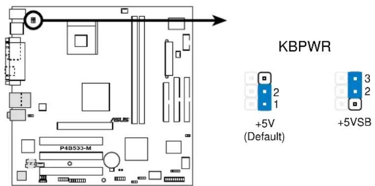
P4B533-M Keyboard Power Setting
3. Line out selector (two 2-pin J3001, J3002) (on audio models only)
By default, these jumpers are shorted (jumper caps on) to route the signal from the audio controller to the rear panel Line Out jack to make it available for audio out devices such as speakers or a headphone. If you connect the Intel Front Panel audio cable to the IPANEL connector (see page 2-26 for the location), remove the caps from these jumpers to allow automatic switching of audio signal between the rear panel Line Out jack and the audio cable.
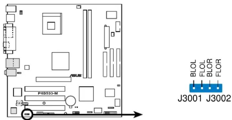
P4B533-M Internal Line Out Selector
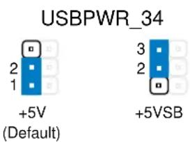
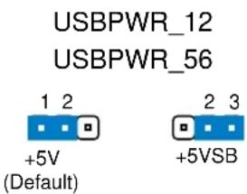
4. USB device wake-up (3-pin USBPWR\_12, USBPWR\_34, USBPWR\_56)
Set these jumpers to +5V to wake up the computer from S1 sleep mode (CPU stopped, DRAM refreshed, system running in low power mode) using the connected USB devices. Set to +5VSB to wake up from S3 sleep mode (no power to CPU, DRAM in slow refresh, power supply in reduced power mode).
The USBPWR_12 and the USBPWR_34 jumpers are for the four rear USB 2.0 ports. The USBPWR_56 is for the internal USB header.

-
This feature requires a power supply that can provide at least 1A on the +5VSB lead when these jumpers are set to +5VSB. Otherwise, the system does not power up.
-
The total current consumed must NOT exceed the power supply capability (+5VSB) whether under normal condition or in sleep mode.
P4B533-M USB Device Wake Up
5. Clear RTC RAM (R200A)
These solder points allow you to clear the Real Time Clock (RTC) RAM in CMOS. You can clear the CMOS memory of date, time, and system setup parameters by erasing the CMOS RTC RAM data. The RAM data in CMOS, that include system setup information such as system passwords, is powered by the onboard button cell battery.
To erase the RTC RAM:
- Turn OFF the computer and unplug the power cord.
- Remove the battery.
- Short the solder points for about 5 seconds.
- Re-install the battery.
-
Plug the power cord and turn ON the computer.
-
Hold down the
key during the boot process and enter BIOS setup to re-enter data.
P4B533-M Clear RTC RAM
CLRTC(R200A)
Short solder points to Clear CMOS
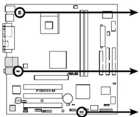
2.8Connectors
This section describes and illustrates the internal connectors on the motherboard.

Always connect ribbon cables with the red stripe to Pin 1 on the connectors. Pin 1 is usually on the side closest to the power connector on hard drives and CD-ROM drives, but may be on the opposite side on floppy disk drives.
1. Hard disk activity LED (2-pin IDE\_LED)
This connector supplies power to the hard disk activity LED. The read or write activities of any device connected to the primary or secondary IDE connector cause this LED to light up.
TIP: If the case-mounted LED does not light up, try reversing the 2-pin plug.

P4B533-M IDE Activity LED
2. Floppy disk drive connector (34-1 pin FLOPPY)
This connector supports the provided floppy drive ribbon cable. After connecting one end to the motherboard, connect the other end to the floppy drive. (Pin 5 is removed to prevent incorrect insertion when using ribbon cables with pin 5 plug).
FLOPPY
NOTE: Orient the red markings on the floppy ribbon cable to PIN 1.
P4B533-M Floppy Disk Drive Connector
3. IDE connectors (40-1 pin PRI\_IDE/SEC\_IDE)
This connector supports the provided UltraDMA/100/66 IDE hard disk ribbon cable. Connect the cable's blue connector to the primary (recommended) or secondary IDE connector, then connect the gray connector to the UltraDMA/100/66 slave device (hard disk drive) and the black connector to the UltraDMA/100/66 master device. It is recommended that you connect non-UltraDMA/100/66 devices to the secondary IDE connector. If you install two hard disks, you must configure the second drive as a slave device by setting its jumper accordingly. Refer to the hard disk documentation for the jumper settings. BIOS supports specific device bootup. If you have more than two UltraDMA/100/66 devices, purchase another UltraDMA/100/66 cable. You may configure two hard disks to be both master devices with two ribbon cables – one for the primary IDE connector and another for the secondary IDE connector.

- Pin 20 on each IDE connector is removed to match the covered hole on the UltraDMA cable connector. This prevents incorrect orientation when you connect the cables.
- The hole near the blue connector on the UltraDMA/100/66 cable is intentional.
P4B533-M IDE Connectors
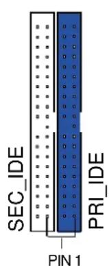
NOTE: Orient the red markings (usually zigzag) on the IDE ribbon cable to PIN 1.
4. ATX power connectors (20-pin ATX\_POWER, 4-pin ATX12V)
These connectors connect to an ATX 12V power supply. The plugs from the power supply are designed to fit these connectors in only one orientation. Find the proper orientation and push down firmly until the connectors completely fit.
In addition to the 20-pin ATXPWR connector, this motherboard requires that you connect the 4-pin ATX +12V power plug to provide sufficient power to the CPU.

Make sure that your ATX 12V power supply can provide 8A on the +12V lead and at least 1A on the +5-volt standby lead (+5VSB). The minimum recommended wattage is 230W, or 300W for a fully configured system. The system may become unstable and may experience difficulty powering up if the power supply is inadequate.
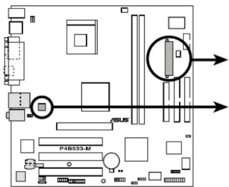
P4B533-M ATX Power Connectors
ATXPWR
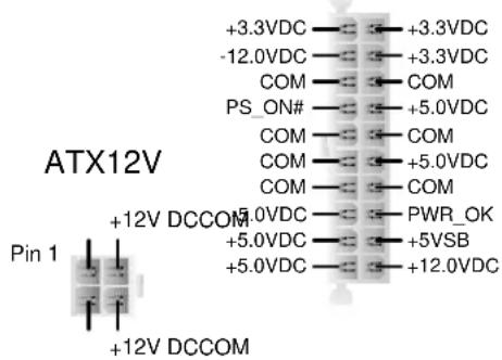
5. CPU and Chassis Fan Connectors (3-pin CPU\_FAN, PWR\_FAN)
The fan connectors support cooling fans of 350mA (4.2 Watts) or a total of 1A (12W) at +12V. Connect the fan cable to the connector matching the black wire to the ground pin.

Do not forget to connect the fan cables to the fan connectors. Lack of sufficient air flow within the system may damage the motherboard components. These are not jumpers! DO NOT place jumper caps over the fan connectors! Doing so will damage the motherboard.
P4B533-M 12-Volt Cooling Fan Power
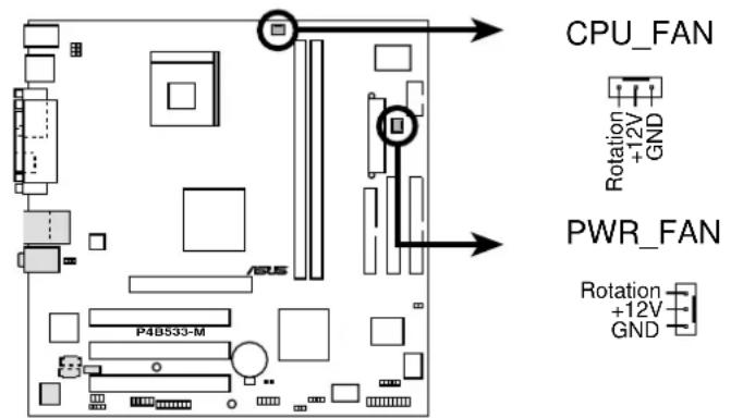
6. Chassis alarm lead (4-1 pin CHASSIS)
This lead is for a chassis designed with intrusion detection feature. This requires an external detection mechanism such as a chassis intrusion sensor or microswitch. When you remove any chassis component, the sensor triggers and sends a high-level signal to this lead to record a chassis intrusion event.
By default, the pins labeled “Chassis Signal” and “Ground” are shorted with a jumper cap. If you wish to use the chassis intrusion detection feature, remove the jumper cap from the pins.
P4B533-M Chassis Alarm Lead
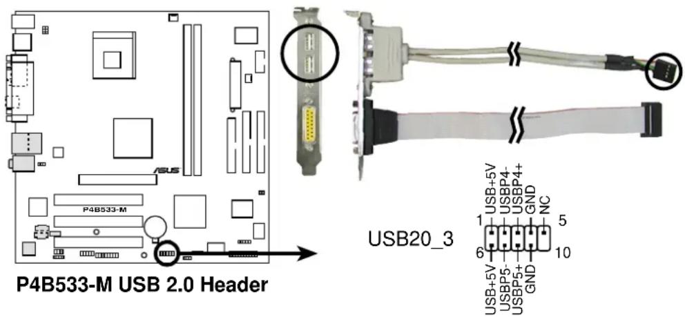
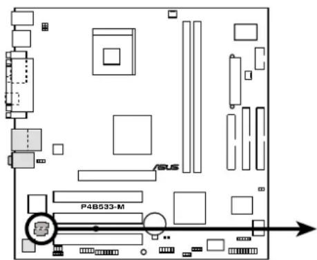
7. USB header (10-1 pin USB20\_3)
If the USB ports on the rear panel are inadequate, a USB header is available for additional USB ports. The USB header complies with USB 2.0 specification that supports up to 480 Mbps connection speed. This speed advantage over the conventional 12 Mbps on USB 1.1 allows faster Internet connection, interactive gaming, and simultaneous running of high-speed peripherals.
If your package came with a USB 2.0/GAME module, connect the USB cable to this header. The module has two USB 2.0 ports that support the next generation USB peripherals such as high resolution cameras, scanners, and printers.

Download the USB 2.0 driver from the Microsoft website (www.microsoft.com). You must install the driver before you can use the USB 2.0 capability.
8. Internal audio connectors (4-pin CD, AUX) (on audio models only)
These connectors allow you to receive stereo audio input from sound sources such as a CD-ROM, TV tuner, or MPEG card.
AUX(White)

CD(Black)
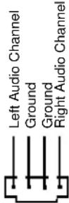
P4B533-M Internal Audio Connectors
9. Infrared module connector (5-pin IR\_CON)
These connectors support an optional wireless transmitting and receiving infrared module. The module mounts to a small opening on system chassis that support this feature. You must also configure the UART2 Use As parameter in BIOS to set UART2 for use with IR.
Use the five pins as shown in Back View and connect a ribbon cable from the module to the motherboard SIR connector according to the pin definitions.
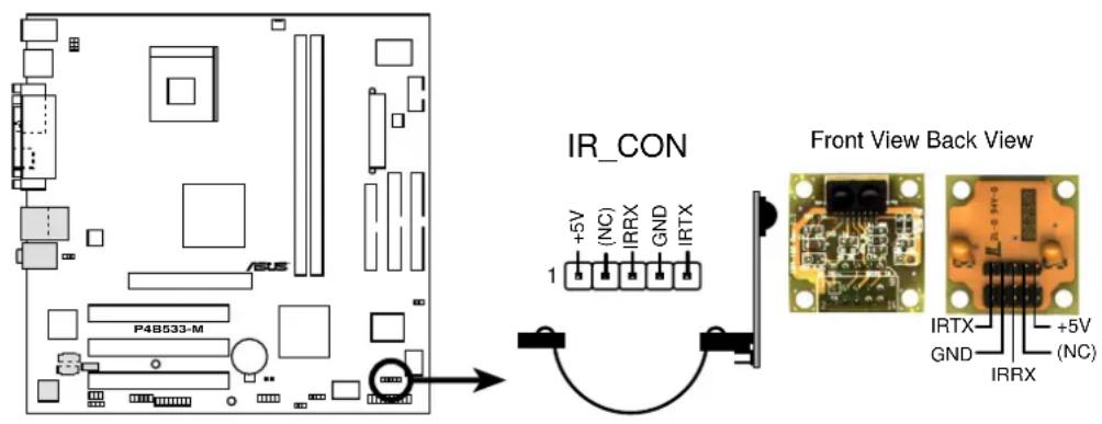
P4B533-M Infrared Module Connector
10. Serial port 2 connector (10-1 pin COM2)
This connector accommodates a second serial port using an optional serial port bracket. Connect the bracket cable to this connector then install the bracket into a slot opening at the back of the system chassis.
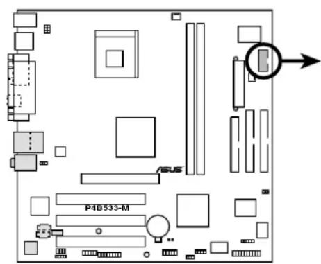
P4B533-M Serial COM2 Bracket
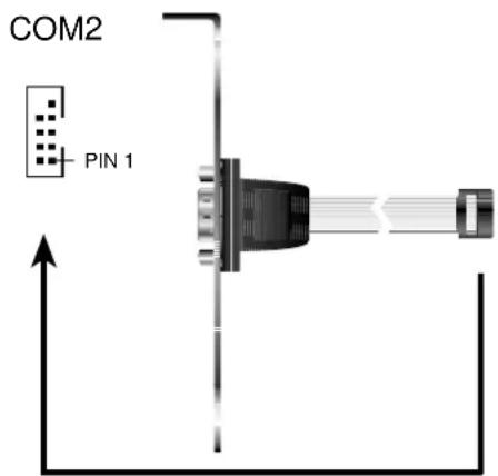
11. GAME/MIDI connector (16-1 pin GAME) (on audio models only)
This connector supports a GAME/MIDI module. If your package came with the optional USB 2.0/GAME module, connect the GAME/MIDI cable to this connector. The GAME/MIDI port on the module connects a joystick or a game pad for playing games, and MIDI devices for playing or editing audio files.
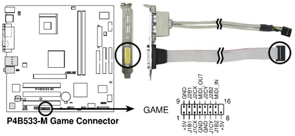
(on audio models only)
This is an interface for the Intel front panel audio cable that allows convenient connection and control of audio devices.

Make sure to remove the caps from the J3001 and J3002 jumpers if you installed the Intel front panel audio cable. Refer to page 2-17 for the location of the jumpers.
P4B533-M Front Panel Audio Connector
13. System panel connector (20-pin PANEL)
This connector is for various system front panel features. See the description of each feature below.
P4B533-M System Panel Connectors
flowchart
graph TD
    A["Message LED"] --> B["SMI Lead"]
    C["Keyboard Lock"] --> D["Power LED"]
    D --> E["+5 V"]
    E --> F["PLED"]
    F --> G["Keylock"]
    G --> H["Ground"]
    H --> I["PWR"]
    I --> J["Ground"]
    J --> K["Reset SW"]
    K --> L["ATX Power Switch*"]
    M["Speaker Connector"] --> N["Ground"]
    N --> O["Ground"]
    O --> P["Ground"]
    P --> Q["Speaker"]
    R["+5 V"] --> S["Message LED"]
    S --> T["ExSMI#"]
    T --> U["PWR"]
    U --> V["Ground"]
    V --> W["Reset SW"]
* Requires an ATX power supply.
- System Power LED Lead (3-1 pin PLED)
This 3-1 pin connector connects to the system power LED. The LED lights up when you turn on the system power, and blinks when the system is in sleep mode.
- System Warning Speaker Lead (4-pin SPEAKER)
This 4-pin connector connects to the case-mounted speaker and allows you to hear system beeps and warnings.
- System Message LED Lead (2-pin MLED)
This 2-pin connector is for the system message LED that indicates receipt of messages from a fax/modem. The normal status for this LED is OFF, when there is no incoming data signal. The LED blinks when data is received. The system message LED feature requires an ACPI OS and driver support.
- System Management Interrupt Lead (2-pin SMI)
This 2-pin connector allows you to manually place the system into a suspend mode, or “green” mode, where system activity is instantly decreased to save power and to expand the life of certain system components. Attach the case-mounted suspend switch to this 2-pin connector.
- ATX Power Switch / Soft-Off Switch Lead (2-pin PWR)
This connector connects a switch that controls the system power. Pressing the power switch turns the system between ON and SLEEP, or ON and SOFT OFF, depending on the BIOS or OS settings. Pressing the power switch while in the ON mode for more than 4 seconds turns the system OFF.
- Reset Switch Lead (2-pin RESET)
This 2-pin connector connects to the case-mounted reset switch for rebooting the system without turning off the system power.
Chapter 3
This chapter describes the power up sequence and gives information on the BIOS beep codes.
Powering up
Chapter summary
3.1 Starting up for the first time.... 3-1
3.2 Powering off the computer 3-2
3.1 Starting up for the first time
- After making all the connections, replace the system case cover.
- Be sure that all switches are off.
- Connect the power cord to the power connector at the back of the system chassis.
- Connect the power cord to a power outlet that is equipped with a surge protector.
- Turn on the devices in the following order:
a. Monitor
b. External SCSI devices (starting with the last device on the chain)
c. System power (if you are using an ATX power supply, you need to switch on the power supply as well as press the ATX power switch on the front of the chassis).
- After applying power, the power LED on the system front panel case lights up. For ATX power supplies, the system LED lights up when you press the ATX power switch. If your monitor complies with “green” standards or if it has a “power standby” feature, the monitor LED may light up or switch between orange and green after the system LED turns on. The system then runs the power-on tests. While the tests are running, the BIOS beeps or additional messages appear on the screen. If you do not see anything within 30 seconds from the time you turned on the power, the system may have failed a power-on test. Check the jumper settings and connections or call your retailer for assistance.
Award BIOS Beep Codes
| Beep Meaning |
| One short beep when No error during POST displaying logo |
| Long beeps in an endless loop No DRAM installed or detected |
| One long beep followed by Video card not found or video card three short beeps memory bad |
| High frequency beeps when CPU overheated; system is working System running at a lower frequency |
- At power on, hold down
to enter BIOS Setup. Follow the instructions in Chapter 4.
3.2 Powering off the computer
You must first exit the operating system and shut down the system before switching off the power. For ATX power supplies, you can press the ATX power switch after exiting or shutting down the operating system. If you use Windows 95/98/2000/XP, click the Start button, click Shut Down, then click the OK button to shut down the computer. The power supply should turn off after Windows shuts down.

The message “You can now safely turn off your computer” does not appear when shutting down with ATX power supplies.
Chapter 4
This chapter tells how to change system settings through the BIOS Setup menus. Detailed descriptions of the BIOS parameters are also provided.
BIOS setup
Chapter summary
4.1 Managing and updating your BIOS .... 4-1
4.2 BIOS Setup program.... 4-7
4.3 Main Menu 4-10
4.4 Advanced Menu 4-17
4.5 Power Menu 4-27
4.6 Boot Menu 4-32
4.7 Exit Menu 4-34
4.1 Managing and updating your BIOS

It is recommended that you save a copy of the motherboard's original BIOS to a bootable floppy disk in case you need to reinstall the original BIOS later.
4.1.1 Using ASUS EZ Flash to update the BIOS
The ASUS EZ Flash feature allows you to easily update the BIOS without having to go through the long process of booting from a diskette and using a DOS-based utility. The EZ Flash is built-in the BIOS firmware so it is accessible by simply pressing
Follow these steps to update the BIOS using ASUS EZ Flash.
- Download the latest BIOS file from the ASUS website (see ASUS contact information on page x). Save the file to a floppy disk.

Write down the BIOS file name on a piece of paper. You need to type the exact BIOS file name at the EZ Flash screen.
- Reboot the computer.
- To use EZ Flash, press
+ right after POST to display the following screen.
ASUS EZ Flash V1.00
Copyright (C) 2002, ASUSTeK COMPUTER INC.

[Onboard BIOS Information]
BIOS Version : ASUS P4B533-M ACPI BIOS Revision 1002
BIOS Model : P4B533-M
BIOS Built Date : 04/16/02

Please Enter File Name for NEW BIOS: _
*Note: EZ Flash will copy file from A:\, Press [ESC] to reboot

The BIOS information in the above screen is for reference only. What you see on your screen may not be exactly the same as shown.
-
Insert the disk that contains the new BIOS file into the floppy drive. You will receive the error message, "WARNING! Device not ready." if you proceed to step 5 without the disk in the drive.
-
At the prompt, "Please Enter File Name for NEW BIOS: _, type in the BIOS file name that you downloaded from the ASUS website, then press
.
EZ Flash will automatically access drive A to look for the file name that you typed. When found, the following message appears on screen.
[BIOS Information in File]
BIOS Version: P4B533-M Boot Block
WARNING! Continue to update the BIOS (Y/N)? _
If you accidentally typed in a wrong BIOS file name, the error message, "WARNING! File not found." appears. Press
- At the above prompt, type Y to continue with the update process. Pressing N exits the EZ Flash screen and reboots the system without updating the BIOS.
The following prompts appear if you typed Y.
Flash Memory: SST 49LF004
1. Update Main BIOS area (Y/N)? _
2. Update Boot Block area (Y/N)? _
- Press Y for both items to completely update the main BIOS area and the boot block area.

DO NOT shutdown or reset the system while updating the BIOS boot block area! Doing so may cause system boot failure.
- When the update process is done, the message, "Press a key to reboot" appears. Press any key to reboot the system with the new BIOS.
4.1.2 Using AFLASH to update the BIOS
Creating a bootable disk
AFLASH.EXE is a Flash Memory Writer utility that updates the BIOS by uploading a new BIOS file to the programmable flash ROM on the motherboard. This file works only in DOS mode. To determine the BIOS version of your motherboard, check the last four numbers of the code displayed on the upper left-hand corner of your screen during bootup. Larger numbers represent a newer BIOS file.
- Type FORMAT A:/S at the DOS prompt to create a bootable system disk. DO NOT copy AUTOEXEC.BAT and CONFIG.SYS to the disk.
- Type COPY D:\AFLASH\AFLASH.EXE A:\ (assuming D is your CD-ROM drive) to copy AFLASH.EXE to the boot disk you created.

AFLASH works only in DOS mode. It does not work in the DOS prompt within Windows, and does not work with certain memory drivers that may be loaded when you boot from the hard drive. It is recommended that you reboot using a floppy disk.
- Reboot the computer from the floppy disk.

BIOS setup must specify "Floppy" as the first item in the boot sequence.
- In DOS mode, type A:\AFLASH
to run AFLASH.
![ASUS ACPI BIOS FLASH MEMORY WRITER U2.0 Copyright (C) 1994-2001 ASUSToK COMPUTER INC. Flash Memory: Winbond W29C020 or SST 29EE020 or Intel 82B02AD Current BIOS Version: ASUS XXX-XX ACPI BIOS Revision 10BEX BIOS Model : XXX-XX BIOS Built Date : 12/25/01 Choose one of the followings: 1. Save Current BIOS To File 2. Update BIOS Including Boot Block and ESCD Enter choice: [1] Press ESC To Exit](/content/2026/05/1128364/images/872beff455151725a3b6a5267222b334ef99222417193feeae40018254f0f445.jpg)

If the word “unknown” appears after Flash Memory:, the memory chip is either not programmable or is not supported by the ACPI BIOS and therefore, cannot be programmed by the Flash Memory Writer utility.
- Select 1. Save Current BIOS to File from the Main menu and press
. The Save Current BIOS To File screen appears.
- Type a filename and the path, for example, A:\XXX-XX.XXX, then press
.
Updating BIOS procedures

Update the BIOS only if you have problems with the motherboard and you are sure that the new BIOS revision will solve your problems. Careless updating may result to more problems with the motherboard!
- Download an updated ASUS BIOS file from the Internet (WWW or FTP) (see ASUS CONTACT INFORMATION on page x for details) and save to the boot floppy disk you created earlier.
- Boot from the floppy disk.
- At the "A:\" prompt, type AFLASH and then press
. - At the Main Menu, type 2 then press
. The Update BIOS Including Boot Block and ESCD screen appears. - Type the filename of your new BIOS and the path, for example, A:\XXX-XX.XXX, then press
.
To cancel this operation, press
- When prompted to confirm the BIOS update, press Y to start the update.
![Update BIOS Including Boot Block and ESCD Flash Memory: Winbond W29C820 or SST 29E020 or Intel 82802AB BIOS Version [CURRENT ] ASUS XXX-XX ACPI BIOS Revision 100X [test.awd] ASUS XXX-XX ACPI BIOS Revision 100X BIOS Model [CURRENT ] XXX-XX [test.awd] XXX-XX Date of BIOS Built [CURRENT ] 09/25/99 [XXXX.XXX] 05/29/00 Check sum of 1001.010 is F26G. Are you sure (Y/N) ? [Y] Press ESC To Return to Main Menu](/content/2026/05/1128364/images/50275005524d9ad3b2071f649526593bf645087f6a22492742d5b5b7cfaf9d64.jpg)
- The utility starts to program the new BIOS information into the Flash ROM. When the programming is done, the message "Flashed Successfully" appears.
![Update BIOS Including Boot Block and ESCD Flash Memory: Winbond U29C0Z6 or SST Z9EE0Z8 or Intel 8Z80ZAB BIOS Version [CURRENT ] ASUS XXX-XX ACPI BIOS Revision 100X [test.awd] ASUS XXX-XX ACPI BIOS Revision 100X BIOS Model [CURRENT ] XXX-XX [test.awd] XXX-XX Date of BIOS Built [CURRENT ] 12/25/01 [XXXX.XXX] 05/29/00 Check sum of 1001.018 is F266. Are you sure (Y/N) ? [Y] Block Erasing -- Done Programming -- 3FFFF Flashed Successfully Press ESC To Continue](/content/2026/05/1128364/images/a3310a24fdfe47781e2829df99cdeaf979d9dcf0b6f229fcdb451a6cc826042f.jpg)
- Follow the onscreen instructions to continue.
![ASUS ACPI BIOS FLASH MEMORY WRITER U2.8 Copyright (C) 1994-2001 ASUSIOK COMPUTER INC. Flash Memory: Winbond U29C020 or SST 29EE920 or Intel 82802AB Current BIOS Version: ASUS XXX-XX ACPI BIOS Revision 100X BIOS Model : XXX-XX BIOS Built Date : 12/25/01 Choose one of the followings: 1. Save Current BIOS To File 2. Update BIOS Including Boot Block and ESCD Enter choice: [1] You have flashed the EPROM: It is recommended that you turn off the power, enter SETUP and LOAD Setup Defaults to have CMOS updated with new BIOS when exits. Press ESC To Exit](/content/2026/05/1128364/images/7271bb92f5516c1bf66a708bc4f476a7b2766b11debe777adef7e713708ac5bd.jpg)

If you encounter problems while updating the new BIOS, DO NOT turn off the system because this may cause boot problems. Just repeat the process, and if the problem persists, load the original BIOS file you saved to the boot disk. If the Flash Memory Writer utility is not able to successfully update a complete BIOS file, the system may not boot. If this happens, call the ASUS service center for support.
4.2 BIOS Setup program
This motherboard supports a programmable Flash ROM that you can update using the provided utility described in section "4.1 Managing and updating your BIOS."
Use the BIOS Setup program when you are installing a motherboard, reconfiguring your system, or prompted to "Run Setup". This section explains how to configure your system using this utility.
Even if you are not prompted to use the Setup program, you may want to change the configuration of your computer in the future. For example, you may want to enable the security password feature or make changes to the power management settings. This requires you to reconfigure your system using the BIOS Setup program so that the computer can recognize these changes and record them in the CMOS RAM.
The Flash ROM on the motherboard stores the Setup utility. When you start up the computer, the system provides you with the opportunity to run this program. Press
If you wish to enter Setup after POST, restart the system by pressing
The Setup program is designed to make it as easy to use as possible. It is a menu-driven program, which means you can scroll through the various sub-menus and make your selections among the predetermined choices.

Because the BIOS software is constantly being updated, the following BIOS setup screens and descriptions are for reference purposes only, and may not exactly match what you see on your screen.
4.2.1 BIOS menu bar
The top of the screen has a menu bar with the following selections:
MAIN Use this menu to make changes to the basic system configuration.
ADVANCED Use this menu to enable and make changes to the advanced features.
POWER Use this menu to configure and enable Power Management features.
BOOT Use this menu to configure the default system device used to locate and load the Operating System.
EXIT Use this menu to exit the current menu or to exit the Setup program.
To access the menu bar items, press the right or left arrow key on the keyboard until the desired item is highlighted.
4.2.2 Legend bar
At the bottom of the Setup screen is a legend bar. The keys in the legend bar allow you to navigate through the various setup menus. The following table lists the keys found in the legend bar with their corresponding functions.
Navigation Key(s) Function Description
| orDisplays the General Help screen from any-where in the BIOS Setup | |
| Jumps to the Exit menu or returns to the main menu from a sub-menu | |
| Left or Right arrow Selects the menu item to the left or right | |
| Up or Down arrow Moves the highlight up or down between fields | |
| - (minus key) Scrolls backward through the values for the highlighted field | |
| + (plus key) or spacebar Scrolls forward through the values for the high-lighted field | |
| Brings up a selection menu for the highlighted field | |
| orMoves the cursor to the first field | |
| orMoves the cursor to the last field | |
| Resets the current screen to its Setup Defaults | |
| Saves changes and exits Setup | |
General help
In addition to the Item Specific Help window, the BIOS setup program also provides a General Help screen. You may launch this screen from any menu by simply pressing
Saving changes and exiting the Setup program
See “4.7 Exit Menu” for detailed information on saving changes and exiting the setup program.
Scroll bar
When a scroll bar appears to the right of a help window, it indicates that there is more information to be displayed that will not fit in the window. Use
Sub-menu
Note that a right pointer symbol (as shown on the left) appears to the left
of certain fields. This pointer indicates that you can display a sub-menu from this field. A sub-menu contains additional options for a field parameter. To display a sub-menu, move the highlight to the field and press
Take some time to familiarize yourself with the
legend keys and their corresponding functions. Practice navigating through the various menus and sub-menus. If you accidentally make unwanted changes to any of the fields, use the set default hot key
4.3 Main Menu
When you enter the Setup program, the following screen appears.
| AwardBIOS Setup Utility | ||||
| Main Advanced Power Boot Exit | ||||
| System Time [22:48:40] System Date [04/11/2002] Legacy Diskette A [1.44M, 3.5 in.] Floppy 3 Mode Support [Disabled]Primary Master [Auto] Primary Slave [Auto] Secondary Master [Auto] Secondary Slave [Auto] Keyboard Features Supervisor Password [Disabled] User Password [Disabled] Halt On [All Errors] Installed Memory 128 MB | Item Specific Help | |||
| (to select field; <+>,<- to change value. | ||||
| F1 Help ↑↓ Select Item -/+ Change Values F5 Setup Defaults ESC Exit ↔ Select Menu Enter Select ▶ Sub-Menu F10 Save and Exit | ||||
System Time [XX:XX:XX]
Sets the system to the time that you specify (usually the current time). The format is hour, minute, second. Valid values for hour, minute and second are Hour: (00 to 23), Minute: (00 to 59), Second: (00 to 59). Use the
System Date [XX/XX/XXXX]
Sets the system to the date that you specify (usually the current date). The format is month, day, year. Valid values for month, day, and year are Month: (1 to 12), Day: (1 to 31), Year: (up to 2099). Use the
Legacy Diskette A [1.44M, 3.5 in.]
Sets the type of floppy drive installed. Configuration options: [None] [360K, 5.25 in.] [1.2M, 5.25 in.] [720K, 3.5 in.] [1.44M, 3.5 in.] [2.88M, 3.5 in.]
Floppy 3 Mode Support [Disabled]
This is required to support older Japanese floppy drives. The Floppy 3 Mode feature allows reading and writing of 1.2MB (as opposed to 1.44MB) on a 3.5-inch diskette. Configuration options: [Disabled] [Enabled]
Supervisor Password [Disabled] / User Password [Disabled]
These fields allow you to set passwords. To set a password, highlight the appropriate field and press
A note about passwords
The BIOS Setup program allows you to specify passwords in the Main menu. The passwords control access to the BIOS during system startup. Passwords are not case sensitive, meaning, passwords typed in either uppercase or lowercase letters are accepted. The BIOS Setup program allows you to specify two different passwords: a Supervisor password and a User password. If you did not set a Supervisor password, anyone can access the BIOS Setup program. If you did, the Supervisor password is required to enter the BIOS Setup program and to gain full access to the configuration fields.
Forgot the password?
If you forget your password, you can clear it by erasing the CMOS Real Time Clock (RTC) RAM. The RAM data containing the password information is powered by the onboard button cell battery. If you need to erase the CMOS RAM, unplug the all the power cables and remove the button cell battery. Re-install the battery after about 2 seconds, then power up the system. Refer to section “4.1 Managing and updating your BIOS” on how to update the BIOS.
Halt On [All Errors]
This field specifies the types of errors that will cause the system to halt. Configuration options: [All Errors] [No Error] [All but Keyboard] [All but Disk] [All but Disk/Keyboard]
Installed Memory [XXX MB]
This field automatically displays the amount of conventional memory detected by the system during the boot process.
4.3.1 Primary and Secondary Master/Slave
| AwardBIOS Setup Utility | |
| Primary Master [Auto] | Item Specific Help |
| Type [Auto] | |
| Cylinders [1024] | to select the type of the IDE drive. [User Type HDD] allows you to set each entry on your own. |
| Head [255] | |
| Sector [63] | |
| CHS Capacity 8422MB | |
| Maximum LBA Capacity 25590MB | |
| Multi-Sector Transfers [Maximum] | WARNING: Ultra DMA mode 3/4/5 can be enabled only when BIOS detects shielded 80-pin cable. |
| SMART Monitoring [Disabled] | |
| PIO Mode [4] | |
| ULTRA DMA Mode [Disabled] | |
| F1 Help ↑↓ Select Item -/+ Change Values F5 Setup Defaults ESC Exit ↔ Select Menu Enter Select ▶ Sub-Menu F10 Save and Exit | |
Type [Auto]
Select [Auto] to automatically detect an IDE hard disk drive. If automatic detection is successful, Setup automatically fills in the correct values for the remaining fields on this sub-menu. If automatic detection fails, this may be because the hard disk drive is too old or too new. If the hard disk was already formatted on an older system, Setup may detect incorrect parameters. In these cases, select [User Type HDD] to manually enter the IDE hard disk drive parameters. Refer to the next section for details.
![ASUS AP130-D5 - Type [Auto] - 1](/content/2026/05/1128364/images/5376b845b2cc0790b6b7d149fcad4b514d4a8d3b6278453b74fbced03f10af1c.jpg)
Before attempting to configure a hard disk drive, make sure you have the correct configuration information supplied by the drive manufacturer. Incorrect settings may cause the system to fail to recognize the installed hard disk.
[User Type HDD]
| AwardBIOS Setup Utility | |
| Primary Master [User Type HDD] | Item Specific Help |
| Type [User Type HDD] Translation Method [LBA] Cylinders [1024] Head [255] Sector [63] CHS Capacity 8422MB Maximum LBA Capacity 25590MB Multi-Sector Transfers [Maximum] SMART Monitoring [Disabled] PIO Mode [4] ULTRA DMA Mode [Disabled] | <Enter> to select the type of the IDE drive. [User Type HDD] allows you to set each entry on your own. WARNING: Ultra DMA mode 3/4/5 can be enabled only when BIOS detects shielded 80-pin cable. |
| F1 Help ↑↓ Select Item -/+ Change Values F5 Setup Defaults ESC Exit ↔ Select Menu Enter Select ▶ Sub-Menu F10 Save and Exit | |
Manually enter the number of cylinders, heads and sectors per track for the drive. Refer to the drive documentation or on the drive label for this information.
![ASUS AP130-D5 - [User Type HDD] - 1](/content/2026/05/1128364/images/9d4c564bf047f3832fbc00be7a36c57daebbdcb39e677856c5c2961f6dbdc7ee.jpg)
After entering the IDE hard disk drive information into BIOS, use a disk utility, such as FDISK, to partition and format new IDE hard disk drives. This is necessary so that you can write or read data from the hard disk. Make sure to set the partition of the Primary IDE hard disk drives to active.
If no drive is installed or if you are removing a drive and not replacing it, select [None].
Other options for the Type field are:
[CD-ROM] - for IDE CD-ROM drives
[LS-120] - for LS-120 compatible floppy disk drives
[ZIP] - for ZIP-compatible disk drives
[MO] - for IDE magneto optical disk drives
[Other ATAPI Device] - for IDE devices not listed here
After making your selections on this sub-menu, press the
Translation Method [LBA]
Select the hard disk drive type in this field. When Logical Block Addressing (LBA) is enabled, the 28-bit addressing of the hard drive is used without regard for cylinders, heads, or sectors. Note that LBA Mode is necessary for drives with more than 504MB storage capacity. Configuration options: [LBA] [LARGE] [Normal] [Match Partition Table] [Manual]
Cylinders
This field configures the number of cylinders. Refer to the drive documentation to determine the correct value. To make changes to this field, set the Type field to [User Type HDD] and the Translation Method field to [Manual].
Head
This field configures the number of read/write heads. Refer to the drive documentation to determine the correct value. To make changes to this field, set the Type field to [User Type HDD] and the Translation Method field to [Manual].
Sector
This field configures the number of sectors per track. Refer to the drive documentation to determine the correct value. To make changes to this field, set the Type field to [User Type HDD] and the Translation Method field to [Manual].
CHS Capacity
This field shows the drive's maximum CHS capacity as calculated by the BIOS based on the drive information you entered.
Maximum LBA Capacity
This field shows the drive's maximum LBA capacity as calculated by the BIOS based on the drive information you entered.
Multi-Sector Transfers [Maximum]
This option automatically sets the number of sectors per block to the highest number that the drive supports. You may also manually configure this field. Refer to the documentation that came with the hard drive to determine the optimum value and set it manually. To make changes to this field, set the Type field to [User Type HDD]. Configuration options: [Disabled] [2 Sectors] [4 Sectors] [8 Sectors] [16 Sectors] [32 Sectors] [Maximum]
SMART Monitoring [Disabled]
This field allows you to enable or disable the S.M.A.R.T. (Self-Monitoring, Analysis and Reporting Technology) system that utilizes internal hard disk drive monitoring technology. This parameter is normally disabled because the resources used in the SMART monitoring feature may decrease system performance. Configuration options: [Disabled] [Enabled]
PIO Mode [4]
This option lets you set a PIO (Programmed Input/Output) mode for the IDE device. Modes 0 through 4 provide successive increase in performance. Configuration options: [0] [1] [2] [3] [4]
Ultra DMA Mode [Disabled]
Ultra DMA capability allows improved transfer speeds and data integrity for compatible IDE devices. Set to [Disabled] to suppress Ultra DMA capability. To make changes to this field, set the Type field to [User Type HDD]. Configuration options: [0] [1] [2] [3] [4] [5] [Disabled]
4.3.2 Keyboard Features
| Keyboard Features | Item Specific Help | |||||
| Boot Up NumLock Status [On] Keyboard Auto-Repeat Rate [6/Sec] Keyboard Auto-Repeat Delay [1/4 Sec] | Select Power-on state for Numlock | |||||
| F1 Help ↑↓ Select Item -/+ Change Values F5 Setup Defaults ESC Exit ↔ Select Menu Enter Select ▶ Sub-Menu F10 Save and Exit | ||||||
Boot Up NumLock Status [On]
This field enables users to activate the Number Lock function upon system boot. Configuration options: [Off] [On]
Keyboard Auto-Repeat Rate [6/Sec]
This controls the speed at which the system registers repeated keystrokes. Options range from 6 to 30 characters per second. Configuration options: [6/Sec] [8/Sec] [10/Sec] [12/Sec] [15/Sec] [20/Sec] [24/Sec] [30/Sec]
Keyboard Auto-Repeat Delay [1/4 Sec]
This field sets the time interval for displaying the first and second characters. Configuration options: [1/4 Sec] [1/2 Sec] [3/4 Sec] [1 Sec]
4.4 Advanced Menu
| AwardBIOS Setup Utility | |||||
| Main Advanced Power Boot Exit | |||||
| Item Specific Help | |||||
| CPU/Memory Frequency Ratio [Auto] | to select. | ||||
| CPU Level 1 Cache [Enabled] | |||||
| CPU Level 2 Cache [Enabled] | |||||
| BIOS Update [Enabled] | |||||
| PS/2 Mouse Function Control [Auto] | |||||
| USB Legacy Support [Auto] | |||||
| OS/2 Onboard Memory >64M [Disabled] | |||||
| Chip Configuration I/O Device Configuration PCI Configuration | |||||
| F1 Help ↑↓ Select Item -/+ Change Values F5 Setup Defaults ESC Exit ↔ Select Menu Enter Select ▶ Sub-Menu F10 Save and Exit | |||||
CPU/Memory Frequency Ratio [Auto]
This field determines whether the memory clock frequency is set to be in synchronous or asynchronous mode with respect to the system frequency. The options that appear in the popup menu vary according to the CPU Frequency (MHz).
Configuration options if your CPU external frequency is greater than or equal to 100MHz but less than 133MHz: [Auto] [1:1] [3:4]
Configuration options if your CPU external frequency is greater than or equal to 133MHz: [Auto] [1:1] [4:3]
CPU Level 1 Cache, CPU Level 2 Cache [Enabled]
These fields allow you to choose from the default [Enabled] or choose [Disabled] to turn on or off the CPU Level 1 and Level 2 built-in cache. Configuration options: [Disabled] [Enabled]
BIOS Update [Enabled]
This field functions as an update loader integrated into the BIOS to supply the processor with the required data. When set to [Enabled], the BIOS loads the update on all processors during system bootup. Configuration options: [Disabled] [Enabled]
PS/2 Mouse Function Control [Auto]
The default setting [Auto] allows the system to detect a PS/2 mouse at startup. If a mouse is detected, the BIOS assigns IRQ12 to the PS/2 mouse. Otherwise, IRQ12 can be used for expansion cards. When you set this field to [Enabled], BIOS reserves IRQ12, whether or not a PS/2 mouse is detected at startup. Configuration options: [Enabled] [Auto]
USB Legacy Support [Auto]
This motherboard supports Universal Serial Bus (USB) devices. The default of [Auto] allows the system to detect a USB device at startup. If detected, the USB controller legacy mode is enabled. If not detected, the USB controller legacy mode is disabled.
When you set this field to [Disabled], the USB controller legacy mode is disabled whether or not you are using a USB device. Configuration options: [Disabled] [Enabled] [Auto]
OS/2 Onboard Memory > 64M [Disabled]
When using OS/2 operating systems with installed DRAM of greater than 64MB, you need to set this option to [Enabled]. Otherwise, leave to the default setting [Disabled]. Configuration options: [Disabled] [Enabled]
4.4.1 Chip Configuration
| Chip Configuration | Item Specific Help | |
| SDRAM Configuration SDRAM CAS Latency SDRAM RAS to CAS Delay SDRAM RAS Precharge Delay SDRAM Active Precharge Delay SDRAM Idle Timer CKx16 Strength Control CKx8 Strength Control DQ DQS Strength Control Graphics Aperture Size AGP Capability Video Memory Cache Mode Memory Hole At 15M-16M Delay Transaction Onboard PCI IDE USB 2.0 HS Reference Voltage | [By SPD] [2.5T] [3T] [3T] [6T] [Infinite] [2.00x] [2.00x] [2.00x] [128MB] [4X Mode] [UC] [Disabled] [Disabled] [Both] [Medium] | <Enter> to select SDRAM configuration. [By SPD] is recommended. [User Defined] allows you to set each configuration on your own. |
| F1 Help ↑↓ Select Item -/+ Change Values F5 Setup Defaults ESC Exit ↔ Select Menu Enter Select ▶ Sub-Menu F10 Save and Exit | ||
SDRAM Configuration [By SPD]
This parameter allows you to set the optimal timings for items 2–5, depending on the memory modules that you are using. The default setting is [By SPD], which configures items 2–5 by reading the contents in the SPD (Serial Presence Detect) device. The EEPROM on the memory module stores critical information about the module, such as memory type, size, speed, voltage interface, and module banks.
Configuration options: [User Defined] [By SPD]
![ASUS AP130-D5 - SDRAM Configuration [By SPD] - 1](/content/2026/05/1128364/images/755ccf5bf438810c7ae10a24245f46381e4b8935b1d050a3fa38be9b6f59dc09.jpg)
The SDRAM parameters (items 2\~5) become configurable only when you set the SDRAM Configuration to [User Defined].
SDRAM CAS Latency [2.5T]
This item controls the latency between the DDR SDRAM read command and the time the data actually becomes available. It is recommended to keep the default setting for stable system operation.
SDRAM RAS to CAS Delay [3T]
This item controls the latency between the DDR SDRAM active command and the read/write command. It is recommended to keep the default setting for stable system operation.
SDRAM RAS Precharge Delay [3T]
This item controls the idle clocks after issuing a precharge command to the DDR SDRAM. It is recommended to keep the default setting for stable system operation.
SDRAM Active Precharge Delay [6T]
This item controls the number of DDR SDRAM clocks used for DDR SDRAM parameters. It is recommended to keep the default setting for stable system operation.
SDRAM Idle Timer [Infinite]
Configuration options: [Infinite] [0T] [8T] [16T] [64T]
CKx16 Strength Control [2.00x]
This item controls the drive strength of the DDR SDRAM clock signal for an x16 device. It is recommended to keep the default setting for stable system operation. Configuration options: [0.75x] [1.00x] [1.25x] [1.50x] [2.00x] [2.50x] [3.00x] [4.00x]
CKx8 Strength Control [2.00x]
This item controls the drive strength of the DDR SDRAM clock signal for an x8 device. It is recommended to keep the default setting for stable system operation. Configuration options: [0.75x] [1.00x] [1.25x] [1.50x] [2.00x] [2.50x] [3.00x] [4.00x]
This item controls the drive strength of the DDR SDRAM signals DQ and DQS. It is recommended to keep the default setting for stable system operation. Configuration options: [0.75x] [1.00x] [1.25x] [1.50x] [2.00x] [2.50x] [3.00x] [4.00x]
Graphics Aperture Size [128MB]
This feature allows you to select the size of mapped memory for AGP graphic data. Configuration options: [4MB] [8MB] [16MB] [32MB] [64MB] [128MB] [256MB]
AGP Capability [4X Mode]
This motherboard supports the AGP 4X interface that transfers video data at 1066MB/s. AGP 4X is backward-compatible, so you may keep the default [4X Mode] even if you are using an AGP 1X video card. When set to [1X Mode], the AGP interface only provides a peak data throughput of 266MB/s even if you are using an AGP 4x card.
Configuration options: [1X Mode] [4X Mode]
Video Memory Cache Mode [UC]
USWC (uncacheable, speculative write combining) is a new cache technology for the video memory of the processor. It can greatly improve the display speed by caching the display data. You must set this to UC (uncacheable) if your display card does not support this feature, otherwise the system may not boot. Configuration options: [UC] [USWC]
Memory Hole At 15M-16M [Disabled]
This field allows you to reserve an address space for ISA expansion cards. Setting the address space to a particular setting makes that memory space unavailable to other system components. Expansion cards can only access memory up to 16MB. Configuration options: [Disabled] [Enabled]
Delayed Transaction [Disabled]
When set to [Enabled], this feature frees the PCI bus when the CPU is accessing 8-bit ISA cards. This process normally consumes about 50-60 PCI clocks without PCI delayed transaction. Set this field to [Disabled] when using ISA cards that are not PCI 2.1 compliant. Configuration options: [Enabled] [Disabled]
Onboard PCI IDE [Both]
This field allows you to enable either the primary IDE channel or secondary IDE channel, or both. You can also set both channels to [Disabled]. Configuration options: [Both] [Primary] [Secondary] [Disabled]
USB 2.0 HS Reference Voltage [Medium]
This item allows control of the USB 2.0 high-speed drive strength reference voltage. Configuration options: [Low] [Medium] [High] [Maximum]
4.4.2 I/O Device Configuration
| AwardBIOS Setup Utility Advanced | |
| I/O Device Configuration | Item Specific Help |
| Floppy Disk Access Control [R/W] Onboard Serial Port 1 [3F8H/IRQ4] Onboard Serial Port 2 [2F8H/IRQ3] UART2 Use As [COM Port] Onboard Parallel Port [378H/IRQ7] Parallel Port Mode [ECP+EPP] ECP DMA Select [3] Onboard AC97 Audio Controller [Auto] Onboard Game Port [200H-207H] Onboard MIDI I/O [Disabled] Onboard MIDI IRQ [10] | <Enter> to select. |
| F1 Help ↑↓ Select Item -/+ Change Values F5 Setup Defaults ESC Exit ←→ Select Menu Enter Select ▶ Sub-Menu F10 Save and Exit | |
Floppy Disk Access Control [R/W]
When set to [Read Only], this parameter protects files from being copied to floppy disks by allowing reads from, but not writes to, the floppy disk drive. The default setting [R/W] allows both reads and writes. Configuration options: [R/W] [Read Only]
Onboard Serial Port 1 [3F8H/IRQ4]
Onboard Serial Port 2 [2F8H/IRQ3]
These fields allow you to set the addresses for the onboard serial connectors. Serial Port 1 and Serial Port 2 must have different addresses. Configuration options: [3F8H/IRQ4] [2F8H/IRQ3] [3E8H/IRQ4] [2E8H/IRQ10] [Disabled]
UART2 Use As [COM Port]
This field allows you to select the device on which to assign UART2. Configuration options: [COM Port] [IR]
Onboard Parallel Port [378H/IRQ7]
This field allows you to set the address of the onboard parallel port connector. If you disable this field, the Parallel Port Mode and ECP DMA Select configurations are not available. Configuration options: [Disabled] [378H/IRQ7] [278H/IRQ5]
Parallel Port Mode [ECP+EPP]
This field allows you to set the operation mode of the parallel port. [Normal] allows normal-speed operation but in one direction only; [EPP] allows bidirectional parallel port operation; [ECP] allows the parallel port to operate in bidirectional DMA mode; [ECP+EPP] allows normal speed operation in a two-way mode. Configuration options: [Normal] [EPP] [ECP] [ECP+EPP]
ECP DMA Select [3]
This field allows you to configure the parallel port DMA channel for the selected ECP mode. This selection is available only if you select [ECP] or [ECP+EPP] in Parallel Port Mode above. Configuration options: [1] [3]
Onboard AC97 Audio Controller [Auto]
[Auto] allows the BIOS to detect whether you are using any AC97 audio device. If a AC97 audio device is detected, the onboard modem/audio controller is enabled; if no AC97 audio device is detected, the controller is disabled. Configuration options: [Disabled] [Auto]
Onboard Game Port [200H-207H]
This field allows you to select the I/O address for the game port. Configuration options: [Disabled] [200H-207H] [208H-20FH]
Onboard MIDI I/O [Disabled]
This field allows you to select the I/O address for the MIDI port. Configuration options: [Disabled] [330H-331H] [300H-301H]
Onboard MIDI IRQ [10]
This field allows you to select the IRQ for the MIDI port. Configuration options: [3] [4] [5] [7] [9] [10] [11] [12] [14] [15]
4.4.3 PCI Configuration
| PCI Configuration | Item Specific Help | |
| Slot 1 IRQ Slot 2 IRQ Slot 3 IRQ PCI/VGA Palette Snoop PCI Latency Timer USB 1.1 Controllers USB 2.0 Controller Primary VGA BIOS Onboard LAN Controller Onboard LAN Boot ROM Onboard 1394 Controller ▶ PCI IRQ Resource Exclusion [Disabled] [32] [3 Controllers] [Enabled] [PCI VGA Card] [Enabled] [Disabled] [Enabled] | <Enter> to select an IRQ. | |
| F1 Help ↑↓ Select Item -/+ Change Values F5 Setup Defaults ESC Exit ↔ Select Menu Enter Select ▶ Sub-Menu F10 Save and Exit | ||
Slot 1, Slot 2, Slot 3 IRQ [Auto]
These fields automatically assign the IRQ for each PCI slot. The default setting for each field is [Auto], which utilizes auto-routing to determine IRQ assignments. Configuration options: [Auto] [NA] [3] [4] [5] [7] [9] [10] [11] [12] [14] [15]
PCI/VGA Palette Snoop [Disabled]
Some non-standard VGA cards, like graphics accelerators or MPEG video cards, may not show colors properly. Setting this field to [Enabled] corrects this problem. If you are using standard VGA cards, leave this field to the default setting [Disabled]. Configuration options: [Disabled] [Enabled]
PCI Latency Timer [32]
Leave this field to the default setting [32] for best performance and stability.
USB 1.1 Controllers [3 Controllers]
This field allows you to select the number of USB 1.1 controllers that you wish to activate. Configuration options: [Disabled] [3 Controllers]
USB 2.0 Controller [Enabled]
This field allows you to enable or disable the onboard USB 2.0 controller. Set to [Enabled] if you wish to install USB 2.0 devices. Configuration options: [Disabled] [Enabled]
Primary VGA BIOS [PCI VGA Card]
This field allows you to select the primary graphics card. Configuration options: [PCI VGA Card] [AGP VGA Card]
Onboard LAN Controller [Enabled]
This field allows you to enable or disable the onboard LAN controller. Keep the setting [Enabled] if you wish to use the LAN feature. Configuration options: [Disabled] [Enabled]
Onboard LAN Boot ROM [Disabled]
This field allows you to enable or disable the option ROM in the onboard LAN chipset. Configuration options: [Disabled] [Enabled]
Onboard 1394 Controller [Enabled]
This parameter allows you to enable or disable the onboard IEEE 1394 controller. Keep the setting [Enabled] if you wish to use the IEEE 1394-compliant digital interface. Otherwise, set to [Disabled] to lessen power consumption. Configuration options: [Disabled] [Enabled]
4.4.3.1 PCI IRQ Resource Exclusion
| PCI IRQ Resource Exclusion | Item Specific Help | |||||
| IRQ 3 Reserved [No/ICU] | Select [Yes] if this IRQ is required by a legacy ISA card and you are not using ICU; otherwise, select [No/ICU]. | |||||
| IRQ 4 Reserved [No/ICU] | ||||||
| IRQ 5 Reserved [No/ICU] | ||||||
| IRQ 7 Reserved [No/ICU] | ||||||
| IRQ 9 Reserved [No/ICU] | ||||||
| IRQ 10 Reserved [No/ICU] | ||||||
| IRQ 11 Reserved [No/ICU] | ||||||
| IRQ 12 Reserved [No/ICU] | ||||||
| IRQ 14 Reserved [No/ICU] | ||||||
| IRQ 15 Reserved [No/ICU] | ||||||
| F1 Help ↑↓ Select Item -/+ Change Values F5 Setup Defaults ESC Exit ↔ Select Menu Enter Select ▶ Sub-Menu F10 Save and Exit | ||||||
IRQ XX Reserved [No/ICU]
These fields indicate whether or not the displayed IRQ for each field is being used by a legacy (non-PnP) ISA card. The setting [No/ICU] for an IRQ field indicates that you are using the ISA Configuration Utility (ICU), and that this particular IRQ is NOT required by a legacy ISA card. Set the IRQ field to [Yes] if you install a legacy ISA card that requires a unique IRQ and you are NOT using ICU. Configuration options: [No/ICU] [Yes]
4.5 Power Menu
The Power menu allows you to reduce power consumption. This feature turns off the video display and shuts down the hard disk after a period of inactivity.
| AwardBIOS Setup Utility | ||||
| Main Advanced Power Boot Exit | ||||
| Power Management [User Defined] Video Off Option [Suspend -> Off] Video Off Method [DPMS OFF] HDD Power Down [Disabled] ACPI Suspend To RAM [Disabled] Suspend Mode [Disabled] PWR Button < 4 Secs [Soft Off] ► Power Up Control ► Hardware Monitor | Item Specific Help | |||
| <Enter> to select the power saving mode. You can select [User Defined] to go to the suspend mode entry below. | ||||
Power Management [User Defined]
This field allows you to activate or deactivate the automatic power saving features. When set to [Disabled], the power management features do not function regardless of the other settings on this menu. The [User Defined] option allows you to set the period of inactivity before the system enters suspend mode. Refer to “Suspend Mode” later in this section.
When set to [Max Saving], system power is conserved to its greatest amount. This setting automatically puts the system into suspend mode after a brief period of system inactivity. [Min Saving] allows the least power saving as the system enters suspend mode only after a long period of inactivity. Configuration options: [User Defined] [Disabled] [Min Saving] [Max Saving]
![ASUS AP130-D5 - Power Management [User Defined] - 1](/content/2026/05/1128364/images/0fff09e74414f198145c7f71264cb1e310f005f0a97a8dd9d7308657adb901a4.jpg)
You should install the Advanced Power Management (APM) utility to keep the system time updated even when the computer enters suspend mode. In Windows 3.x and Windows 95, you need to install Windows with the APM feature. In Windows 98 or later, APM is automatically installed as indicated by a battery and power cord icon labeled "Power Management" in the Control Panel. Select the item "Advanced" in the Power Management Properties dialog box.
Video Off Option [Suspend -> Off]
This field determines when to activate the video off feature for monitor power management. Configuration options: [Always On] [Suspend -> Off]
Video Off Method [DPMS OFF]
This field defines the video off features. The Display Power Management System (DPMS) feature allows the BIOS to control the video display card if it supports the DPMS feature. [Blank Screen] only blanks the screen. Use this for monitors without power management or “green” features.
![ASUS AP130-D5 - Video Off Method [DPMS OFF] - 1](/content/2026/05/1128364/images/d7ba4f6eadb729e59e16307195a8561e6ee3bd24df4b282e9e6ce1a0327636ae.jpg)
Even if installed, your screen saver does not display when you select [Blank Screen] for the above field.
[V/H SYNC+Blank] blanks the screen and turns off vertical and horizontal scanning. Configuration options: [Blank Screen] [V/H SYNC+Blank] [DPMS Standby] [DPMS Suspend] [DPMS OFF] [DPMS Reduce ON]
HDD Power Down [Disabled]
Shuts down any IDE hard disk drives in the system after a period of inactivity as set in this user-configurable field. This feature does not affect SCSI hard drives. Configuration options: [Disabled] [1 Min] [2 Min] [3 Min]...[15 Min]
ACPI Suspend To RAM [Disabled]
This field allows you to enable or disable the ACPI Suspend-to-RAM feature. To support this feature, the +5VSB of the power supply should have the capacity to provide more than 720mA current. Configuration options: [Disabled] [Enabled]
Suspend Mode [Disabled]
Sets the time period before the system goes into suspend mode. Configuration options: [Disabled] [1\~2 Min] [2\~3 Min] [4\~5 min] [8\~9 Min] [20 Min] [30 Min] [40 Min] [1 Hour]
PWR Button < 4 Secs [Soft Off]
When set to [Soft off], the ATX switch can be used as a normal system power-off button when pressed for less than 4 seconds. [Suspend] allows the button to have a dual function where pressing less than 4 seconds puts the system in sleep mode. Regardless of the setting, holding the ATX switch for more than 4 seconds powers off the system. Configuration options: [Soft off] [Suspend]
4.5.1 Power Up Control
| Power Up Control | Item Specific Help | |||||
| AC Power Loss Restart Wake/Power Up On Ext. Modem Power Up On PCI Card Power On By PS/2 Keyboard Power On By PS/2 Mouse Automatic Power Up [Disabled] | ||||||
| F1 Help ↑↓ Select Item -/+ Change Values F5 Setup Defaults ESC Exit ↔ Select Menu Enter Select ▶ Sub-Menu F10 Save and Exit | ||||||
AC PWR Loss Restart [Disabled]
This allows you to set whether or not to reboot the system after power interruptions. [Disabled] leaves your system off while [Enabled] reboots the system. [Previous State] sets the system back to the state it was before the power interruption. Configuration options: [Disabled] [Enabled] [Previous State]
Wake/Power Up On Ext. Modem [Disabled]
This allows either settings of [Enabled] or [Disabled] for waking/powering up the computer when the external modem receives a call while the computer is in Standby/Soft-off mode. Configuration options: [Disabled] [Enabled]
![ASUS AP130-D5 - Wake/Power Up On Ext. Modem [Disabled] - 1](/content/2026/05/1128364/images/8d4c95b80563a73af4b0e127a0a2ec6e4758b07a40fba92d47f35ac0b02ec6c2.jpg)
The computer cannot receive or transmit data until the computer and applications are fully running. Thus, connection cannot be made on the first try. Turning an external modem off and then back on while the computer is off causes an initialization string that turns the system power on.
Power Up On PCI Card [Disabled]
When set to [Enabled], this parameter allows you to turn on the system through a PCI LAN or modem card. This feature requires an ATX power supply that provides at least 1A on the +5VSB lead.
Configuration options: [Disabled] [Enabled]
Power On By PS/2 Keyboard [Disabled]
This parameter allows you to use specific keys on the keyboard to turn on the system. This feature requires an ATX power supply that provides at least 1A on the +5VSB lead. Configuration options: [Disabled] [Space Bar] [Ctrl-Esc] [Power Key]
Power On By PS/2 Mouse [Disabled]
When set to [Enabled], this parameter allows you to use the PS/2 mouse to turn on the system. This feature requires an ATX power supply that provides at least 1A on the +5VSB lead. Configuration options: [Disabled] [Enabled]
Automatic Power Up [Disabled]
This allows an unattended or automatic system power up. You may configure your system to power up at a certain time of the day by selecting [Everyday] or at a certain time and day by selecting [By Date].
Configuration options: [Disabled] [Everyday] [By Date]
4.5.2 Hardware Monitor
| Hardware Monitor | Item Specific Help | |||||
| CPU Temperature 41°C/105.5°F CPU Fan Speed 7500RPM Power Fan Speed 5335RPM VCORE Voltage 1.50V +3.3V Voltage 3.47V +5V Voltage 4.91V +12V Voltage 12.09V | <Enter> to switch between monitoring or ignoring. | |||||
| F1 Help ↑↓ Select Item -/+ Change Values F5 Setup Defaults ESC Exit ↔ Select Menu Enter Select ▶ Sub-Menu F10 Save and Exit | ||||||
CPU Temperature [xxxC/xxxF]
The onboard hardware monitor automatically detects and displays the CPU temperature.
CPU Fan Speed [xxxxRPM] or [N/A] Power Fan Speed [xxxxRPM] or [N/A]
The onboard hardware monitor automatically detects and displays the CPU and power fan speeds in rotations per minute (RPM). If any of the fans is not connected to the motherboard, the specific field shows N/A.
VCORE Voltage, +3.3V Voltage, +5V Voltage, +12V Voltage
The onboard hardware monitor automatically detects the voltage output through the onboard voltage regulators.

If any of the monitored items is out of range, the following error message appears: "Hardware Monitor found an error. Enter Power setup menu for details". You will then be prompted to "Press F1 to continue or DEL to enter SETUP".
4.6 Boot Menu
| AwardBIOS Setup Utility | ||||
| Main Advanced Power Boot Exit | ||||
| 1. Removable Device [Legacy Floppy] 2. IDE Hard Drive [None] 3. ATAPI CD-ROM [None] 4. Other Boot Device [INT18 Device (Networ)] Plug & Play 0/S [No] Boot Virus Detection [Enabled] Quick Power On Self Test [Enabled] Boot Up Floppy Seek [Enabled] Full Screen Logo [Enabled] Interrupt Mode [APIC] | Item Specific Help | |||
| Boot Sequence: <Enter> to select the device. To select the boot sequence, use the up or down arrow. Press <-> to move the device up the list, or <-> to move it down the list. | ||||
| F1 Help ↑↓ Select Item -/+ Change Values F5 Setup Defaults ESC Exit ↔ Select Menu Enter Select ▶ Sub-Menu F10 Save and Exit | ||||
Boot Sequence
The Boot menu allows you to select among the four possible types of boot devices listed using the up and down arrow keys. By using the <+> or
Removable Device [Legacy Floppy]
Configuration options: [Disabled] [Legacy Floppy] [LS-120] [ZIP] [ATAPI MO]
IDE Hard Drive
This field allows you to select which IDE hard disk drive to use in the boot sequence. Pressing [Enter] will show the product IDs of all connected IDE hard disk drives.
ATAPI CD-ROM
This field allows you to select which ATAPI CD-ROM drive to use in the boot sequence. Pressing [Enter] will show the product IDs of all your connected ATAPI CD-ROM drives.
Other Boot Device Select [INT18 Device (Network)]
Configuration options: [Disabled] [SCSI Boot Device] [INT18 Device (Network)]
Plug & Play O/S [No]
This field allows you to use a Plug-and-Play (PnP) operating system to configure the PCI bus slots instead of using the BIOS. When [Yes] is selected, interrupts may be reassigned by the OS. If you installed a non-PnP OS or if you want to prevent reassigning of interrupt settings, keep the default setting [No]. Configuration options: [No] [Yes]
Boot Virus Detection [Enabled]
This field allows you to set boot virus detection, ensuring a virus-free boot sector. The system halts and displays a warning message when it detects a virus. If this occurs, you can either allow the operation to continue or use a virus-free bootable floppy disk to restart and investigate your system. Configuration options: [Disabled] [Enabled]
Quick Power On Self Test [Enabled]
This field speeds up the Power-On-Self Test (POST) routine. Configuration options: [Disabled] [Enabled]
Boot Up Floppy Seek [Enabled]
When enabled, the BIOS will seek the floppy disk drive to determine whether the drive has 40 or 80 tracks. Configuration options: [Disabled] [Enabled]
Full Screen Logo [Enabled]
This allows you to enable or disable the full screen logo display feature. Configuration options: [Disabled] [Enabled]
Interrupt Mode [APIC]
The Advanced Programmable Interrupt Controller (APIC) setting allows you to distribute interrupt routings other than the 16 IRQs. The Programmable Interrupt Controller (PIC) setting allows you to use the 16 IRQs only. Configuration options: [PIC] [APIC]
4.7 Exit Menu
When you have made all of your selections from the various menus in the Setup program, save your changes and exit Setup. Select Exit from the menu bar to display the following menu.
| AwardBIOS Setup Utility | |
| Main Advanced Power Boot Exit | |
| Exit Saving Changes Exit Discarding Changes Load Setup Defaults Discard Changes Save Changes | Item Specific Help |
| Exit setup utility and save your changes to CMOS. | |
| F1 Help ↑↓ Select Item -/+ Change Values F5 Setup Defaults ESC Exit ↔ Select Menu Enter Select ▶ Sub-Menu F10 Save and Exit | |

Pressing
Exit Saving Changes
Once you are finished making your selections, choose this option from the Exit menu to ensure the values you selected are saved to the CMOS RAM. The CMOS RAM is sustained by an onboard backup battery and stays on even when the PC is turned off. When you select this option, a confirmation window appears. Select [Yes] to save changes and exit.

If you attempt to exit the Setup program without saving your changes, the program prompts you with a message asking if you want to save your changes before exiting. Pressing
Exit Discarding Changes
Select this option only if you do not want to save the changes that you made to the Setup program. If you made changes to fields other than system date, system time, and password, the BIOS asks for a confirmation before exiting.
Load Setup Defaults
This option allows you to load the default values for each of the parameters on the Setup menus. When you select this option or if you press
Discard Changes
This option allows you to discard the selections you made and restore the previously saved values. After selecting this option, a confirmation appears. Select [Yes] to discard any changes and load the previously saved values.
Save Changes
This option saves your selections without exiting the Setup program. You can then return to other menus and make further changes. After you select this option, a confirmation window appears. Select [Yes] to save any changes to the non-volatile RAM.
Chapter 5
This chapter describes the contents of the support CD that comes with the motherboard package.
Software support
Chapter summary
5.1 Install an operating system.... 5-1
5.2 Support CD information 5-1
5.3 Software information 5-9
5.1 Install an operating system
This motherboard supports Windows 98/ME/NT/2000/XP and OS/2 operating system (OS). Always install the latest OS version and corresponding updates so you can maximize the features of your hardware.

Because motherboard settings and hardware options vary, use the setup procedures presented in this chapter for general reference only. Refer to your OS documentation for more information.
5.2 Support CD information
The support CD that came with the motherboard contains useful software and several utility drivers that enhance the motherboard features.

The contents of the support CD are subject to change at any time without notice. Visit the ASUS website for updates.
5.2.1 Running the support CD
To begin using the support CD, simply insert the CD into your CD-ROM drive. The CD automatically displays the welcome screen and the installation menus if Autorun is enabled in your computer.

If the welcome screen did not appear automatically, locate and double-click on the file ASSETUP.EXE from the BIN folder in the support CD to display the menus.
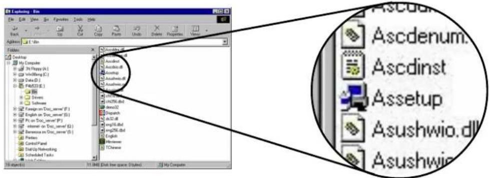
5.2.2 Main menu
From the welcome screen, the program takes you directly to the main menu. The main menu displays an image of the motherboard, and the buttons and icons that link you to the software, drivers, utilities, and other information contained in the support CD.
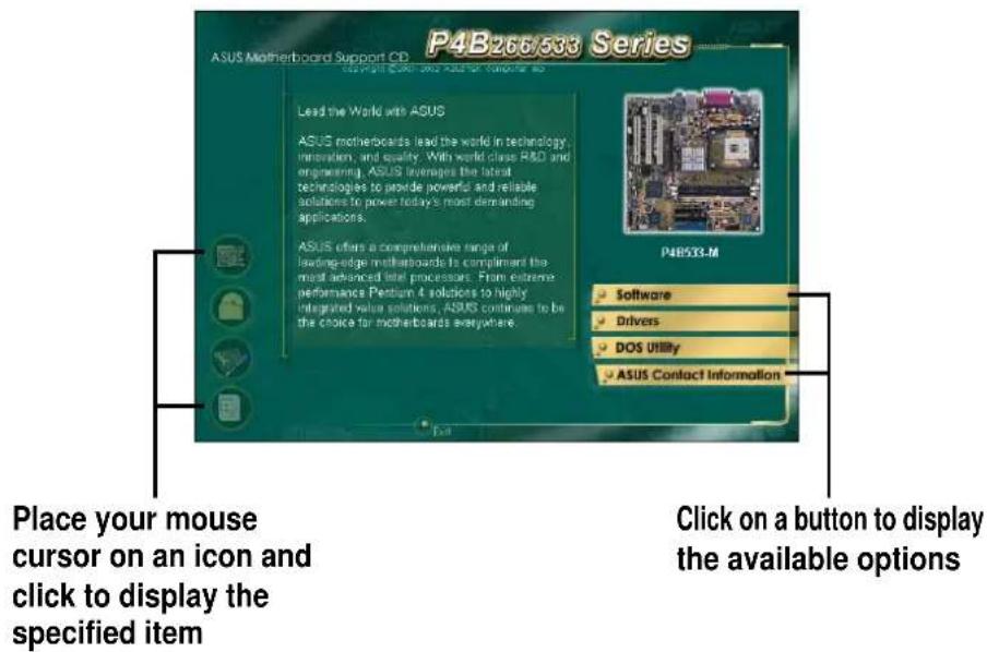
5.2.3 Software menu
The software menu shows the applications and other software that the motherboard supports. The highlighted items indicate that they are available for your motherboard. Simply click on a specific item then follow the installation wizard to install it.
The software menu is composed of two screens. Click on the Next button on the lower right corner of the first screen to display the second menu screen. To return to the first menu screen, click on the Back button on the lower right corner of the second screen.
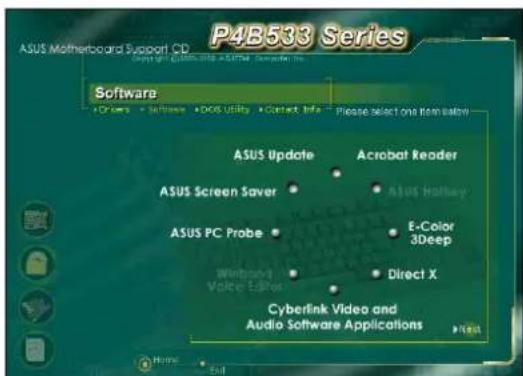
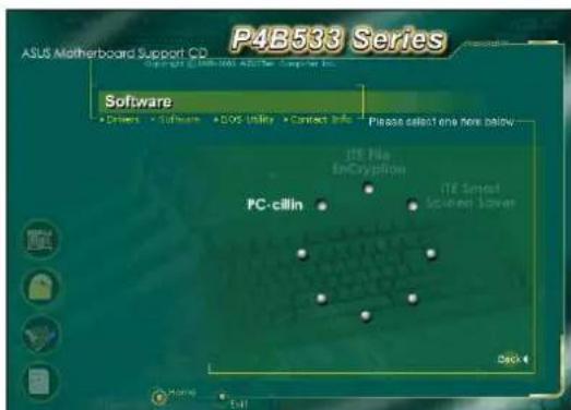
ASUS Update
This program allows you to download the latest version of the BIOS from the ASUS website.

Before using the ASUS Update, make sure that you have an Internet connection so you can connect to the ASUS website.
ASUS Screen Saver
This item installs the ASUS screen saver.
ASUS PC Probe
This smart utility monitors the fan speed, CPU temperature, and system voltages, and alerts you on any detected problems. This utility helps you keep your computer at a healthy operating condition.
Cyberlink Video and Audio Applications
This item installs the Cyberlink PowerPlayer SE 5.0 and Cyberlink VideoLive Mail 4.0.
Direct X
This item installs the Microsoft V8.0a driver.
E-Color 3Deep
This item installs the 3Deep software. 3Deep is the first application that gives online gamers the competitive edge in multi-player skirmishes. This application removes dark washed-out graphics to deliver true vibrant colors.
Acrobat Reader
This item installs the Adobe Acrobat Reader V5.0. The Acrobat Reader software is for viewing files saved in Portable Document Format (PDF).
PC-cillin
This item installs the PC-cillin 2002 V9.02 anti-virus software. View the PC-cillin online help for detailed information.
5.2.4 Drivers menu
The drivers menu shows the available device drivers if the system detects installed devices. Install the necessary drivers to activate the devices.
The drivers menu is composed of two screens. Click on the Next button on the lower right corner of the first screen to display the second menu screen. To return to the first menu screen, click on the Back button on the lower right corner of the second screen.
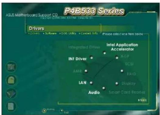
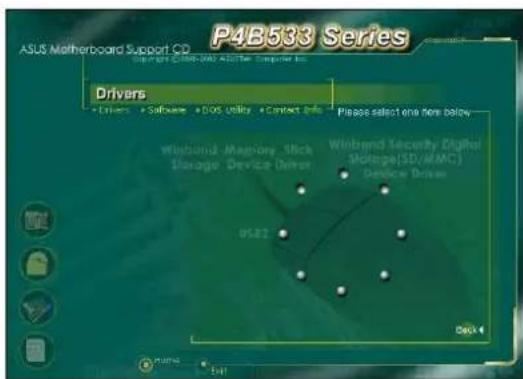
INF Driver
This item installs the Intel® Chipset Software Installation Utility that enables Plug-n-Play INF support for Intel chipset components. This utility installs to the target system the Windows INF files that outline to the operating system how the chipset components will be configured.
You may install this utility in three modes: interactive, silent, and unattended preload. The interactive mode requires user input during installation. This is not required in the silent and unattended preload modes.
Refer to the online help or readme file that came with the utility.
Intel® Application Accelerator
This item installs the Intel Application Accelerator for Microsoft® Windows® 98/98SE/ME/NT4.0/2000. This program is designed to improve performance of the storage sub-system and overall system performance.

Install the INF Driver before installing the Intel Application Accelerator.
LAN
This item installs the Fast Ethernet LAN driver.
Audio Utility
This item installs the C-Media audio driver.
USB2

The Microsoft USB 2.0 driver has not been officially released as of the support CD production date. Please download the USB 2.0 driver from the Microsoft website (www.microsoft.com) to upgrade your USB 1.1 ports to USB 2.0.
5.2.5 DOS Utility menu
The DOS utilities menu includes items that you can run in DOS mode. These items are also present in the software menu.
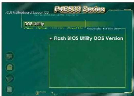
5.2.6 ASUS Contact Information
Clicking the ASUS Contact Information button displays as stated. You may also find this information on page x of this user guide.
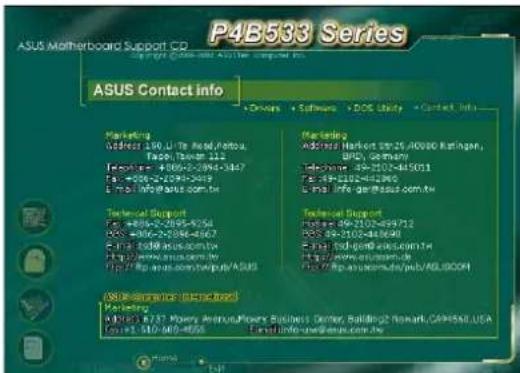
5.2.7 Other information
The icons on the left side of the screen give additional information on the motherboard and the contents of the support CD. This section shows the pop-up windows that appear when you click the icons.
Motherboard Info
The window displays the general specifications of the P4B533-M motherboard.
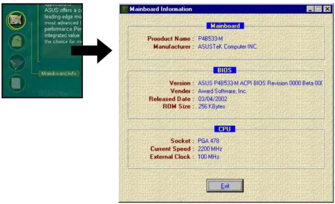
Browse this CD
The window displays the support CD contents in graphical format.
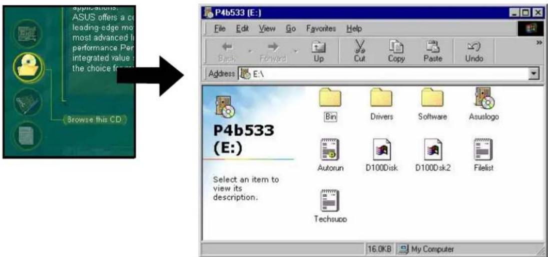
Technical Support Form
The window displays the ASUS Technical Support Request Form that you have to fill up when requesting technical support.
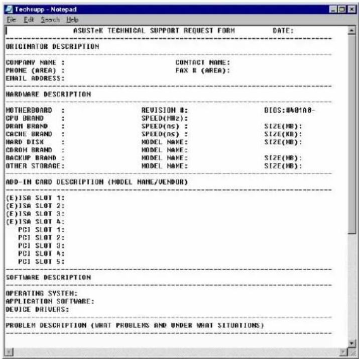
Readme
The window displays the contents of the support CD and a brief description of each in text format.

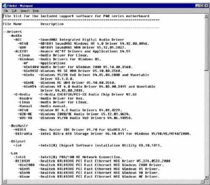
5.3 Software information
Most of the applications in the support CD have wizards that will conveniently guide you through the installation. View the online help or readme file that came with the software for more information.
This section provides details on the software applications that the motherboard supports.
5.3.1 ASUS Update
The ASUS Update is a utility that allows you to update the motherboard BIOS and drivers. This utility requires an Internet connection either through a network or an Internet Service Provider (ISP).
Follow these steps to use the ASUS Update.
- Launch the utility from your Windows Start menu:
Programs/AsusUpdate Vx.xx.xx/AsusUpdate
The ASUS Update initial screen appears.
-
Select your desired update method, then click Next.
-
If you selected updating/ downloading from the Internet, select the ASUS FTP site nearest you to avoid network traffic, or choose Auto Select. Click Next.
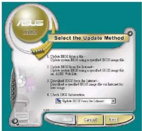
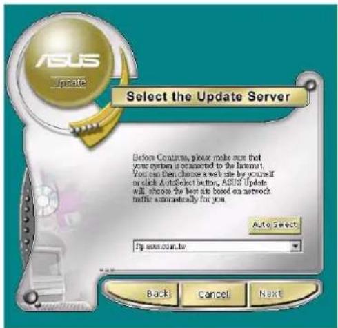
- From the FTP site, select the BIOS version that you wish to download. Click Next.
- Follow the instructions on the succeeding screens to complete the update process.
If you selected the option to update the BIOS from a file, a window pops up prompting you to locate the file. Select the file, click Save, then follow the screen instructions to complete the update process.
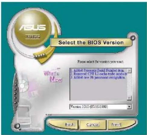
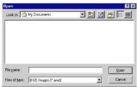
5.3.2 ASUS PC Probe
The ASUS PC Probe is a convenient utility to continuously monitor your computer system's vital components, such as fan rotations, voltages, and temperatures. It also has a utility that lets you review useful information about your computer, such as hard disk space, memory usage, and CPU type, CPU speed, and internal/external frequencies through the DMI Explorer.
Starting ASUS PC Probe
When ASUS PC Probe starts, a splash screen appears allowing you to select whether to show the screen again when you open PC Probe or not. To bypass this startup screen, clear the Show up in next execution check box.

To launch ASUS PC Probe, click the Windows Start button, point to Programs, and then ASUS Utility, and then click Probe Vx.xx.
The PC Probe icon 📄 appears on the taskbar system tray indicating that ASUS PC Probe is running. Clicking the icon allows you to see the status of your PC.

Using ASUS PC Probe
Monitoring
Monitor Summary
Shows a summary of the items being monitored.
Temperature Monitor
Shows the PC temperature (for supported processors only).
Temperature Warning threshold adjustment (Move the slider up to increase the threshold level or down to decrease the threshold level)
Fan Monitor
Shows the PC fan rotation.
Fan Warning threshold adjustment (Move the slider up to increase the threshold level or down to decrease the threshold level)
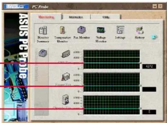
Voltage Monitor
Shows the PC voltages.
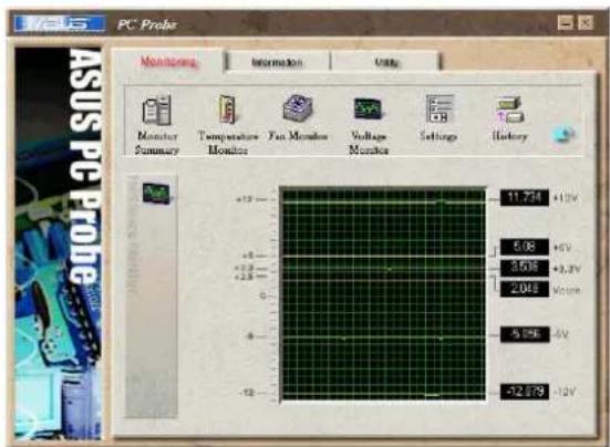
Settings
Lets you set threshold levels and polling intervals or refresh times of the PC's temperature, fan rotation, and voltages.

CPU Cooling System Setup
Lets you select when to enable software CPU cooling. When When CPU Overheated is selected, the CPU cooling system is enabled whenever the CPU temperature reaches the threshold value.
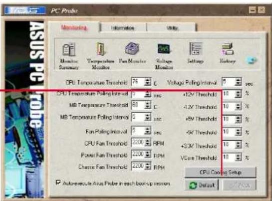
History
Lets you record the monitoring activity of a certain component of your PC for future reference.
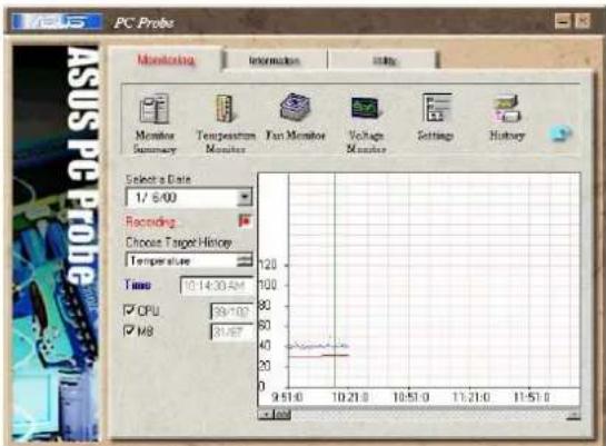
Fan Control
Lets you enable/disable Smart Fan Control. Smart Fan Control adjusts the fan speed automatically based on the current CPU temperature and predefined threshold.
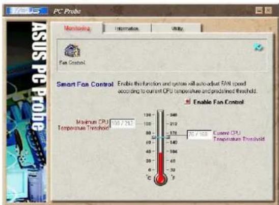
Hard Drives
Shows the used and free space of the PC's hard disk drives and the file allocation table or file system used.
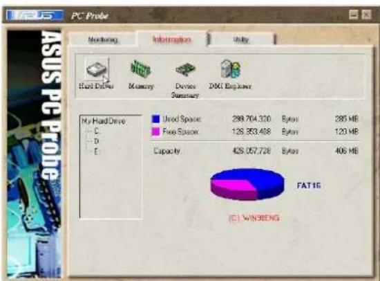
pie
FAT1G (C1 WIN 98ENG) | Component | Value | | :--- | :--- | | Used Space | 298.704.320 | | Bytes | 285 MB | | Free Space | 126.563.408 | | Bytes | 120 MB | | Capacity | 428.057.728 | | Bytes | 406 MB |Information
Memory
Shows the PC memory load, memory usage, and paging file usage.
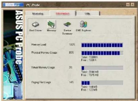
bar
| Category | Percentage (%) | | :--- | :--- | | Memory Load | 100 | | Physical Memory Usage | 93 | | Virtual Memory Usage | 3 | | Paging File Usage | 14 |Device Summary
Shows a summary of devices present in your PC.
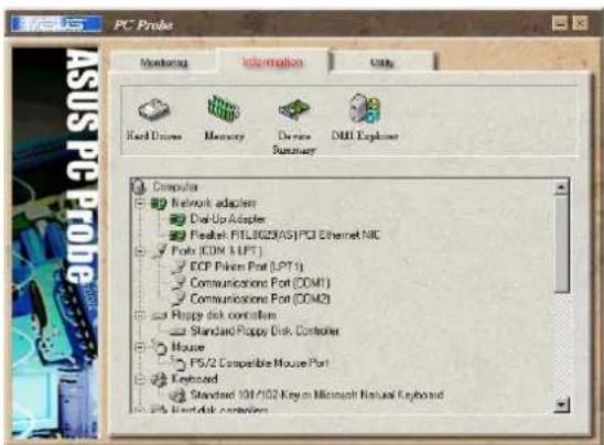
DMI Explorer
Shows information pertinent to the PC, such as CPU type, CPU speed, and internal/external frequencies, and memory size.
Utility
Lets you run programs outside of the ASUS Probe modules. To run a program, click Execute Program.
NOTE: This feature is currently unavailable.
ASUS PC Probe Task Bar Icon
Right clicking the PC Probe icon brings up a menu to open or exit ASUS PC Probe and pause or resume all system monitoring.

When the ASUS PC Probe senses a problem with your PC, portions of the ASUS PC Probe icon changes to red, the PC speaker beeps, and the ASUS PC Probe monitor appears.

5.3.3 E-Color 3Deep
The 3Deep color tuner is designed to match your CRT or LCD color monitor and maximize the color quality of all graphical applications. You may also tune your internet applications to match “true” internet source colors with the color displayed on the monitor.
3Deep Control Panel
Using the Windows Start button, activate the 3Deep Control Panel program from the 3Deep Applications group on the Main Program menu.
The control panel offers access to the Color Wizard tuning program, a Game Gamma setting and a Tweak slider for brightness adjustment.
3Deep Color Tuning
- Select the type of monitor connected to the computer, either CRT or LCD.
- Follow the instructions to manually adjust the brightness level of the monitor.
- Select the faintest of the three colors: blue, red, and green.
- Select the color squares that most closely blend and match with the background.
- The next step repeats the color matching process to achieve full color quality.
- When a message appears indicating that the tuning process is complete, click Finish.
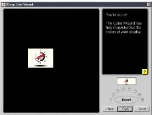
- Click on the Set Up Now button to connect to the Internet. Follow the screen instructions to set up True Internet Color.

Glossary
This part lists the technical terms that you may encounter when reading this document.
- 1394 is the IEEE designation for a high performance serial bus that offers data transfers at 100/200/400 Mbps. This serial bus defines both a back plane physical layer and a point-to-point cable-connected virtual bus. The primary application of the cable version is the integration of I/O connectivity at the back panel of personal computers using a low-cost, scalable, high-speed serial interface. The 1394 standard also provides new services such as live connect/disconnect capability for external devices including disk drives, printers and hand-held peripherals such as scanners and cameras. This is a new standard to complement the slower USB interface and to compete with the more expensive SCSI interface.
AC'97 (Audio Codec '97). AC '97 is the next step in enabling PCs with audio quality comparable to consumer electronics devices. The specification defines new cost-effective options to help integrate the components necessary to support next-generation auto-intensive PC applications such as DVD, 3-D multiplayer gaming and interactive music. The specification also defines new extensions supporting modem and docking to help both desktop and mobile manufacturers adopt these new technologies more quickly and cost-effectively. This specification uses software emulation to compete with the PCI SoundBlaster specification.
ACPI (Advanced Configuration and Power Interface). The ACPI specification defines a cross-platform interface designed to support many operating systems. ACPI defines a flexible and abstract hardware interface that provides a standard way to integrate power management features in a PC system, including hardware, operating system and application software. This enables the system to automatically turn ON and OFF peripherals such as CD-ROMs, network cards, hard disk drives, and printers, as well as consumer devices connected to the PC such as VCRs, TVs, phones, and stereos. With this technology, peripherals are also able to activate the PC. For example, inserting a tape into a VCR can turn on the PC, which could then activate a large-screen TV and high-fidelity sound system.
AGP (Accelerated Graphics Port). An interface specification that enables high-performance 3D graphics on mainstream PCs. AGP was designed to offer the necessary bandwidth and latency to perform texture mapping directly from system memory.
| Bus Bus Frequency Bandwidth Data Transfer Rate |
| PCI 33MHz 33MHz 133MByte/sec |
| AGP 1X 66MHz 66MHz 266MByte/sec |
| AGP 2X 66MHz 133MHz 512MByte/sec |
| AGP 4X 66MHz 266MHz 1024MByte/sec |
Backup. A copy of a file, directory, or volume on a separate storage device from the original. This copy is for the purpose of data retrieval in case the original is accidentally erased, damaged, or destroyed.
BIOS (Basic Input/Output System). BIOS is a set of routines that control how the computer transfers data between computer components, such as memory, disks, and the display adapter. The BIOS instructions are built into the computer's read-only memory. BIOS parameters are configurable through the BIOS Setup program. You can update the BIOS using the AFLASH utility by copying a new BIOS file into the EEPROM.
Bit (Binary Digit). Represents the smallest unit of data used by the computer. A bit can have one of two values: 0 or 1.
Boot. Boot means to start the computer operating system by loading it into system memory. When the manual instructs you to “boot” your system (or computer), it means to turn ON your computer. “Reboot” means to restart your computer. When using Windows 95 or later, selecting “Restart” from “Start | Shut Down...” will reboot your computer.
Bus Master IDE. PIO (Programmable I/O) IDE requires that the CPU be involved in IDE access and waiting for mechanical events. Bus master IDE transfers data to/from the memory without interrupting the CPU. Bus master IDE driver and bus master IDE hard disk drives are required to support bus master IDE mode.
Byte (Binary Term). One byte is a group of eight contiguous bits. A byte is used to represent a single alphanumeric character, punctuation mark, or other symbol.
Cache Memory. A type of RAM that allows a faster from the CPU than a regular RAM. The cache memory eliminates the CPU wait state. When the CPU reads data from the main memory, a copy of this data is stored in the cache memory. The next time the same address, the data is transferred from the cache memory instead of from the main memory.
CODEC (Compressor/Decompressor). A software component that translates video or audio between its uncompressed form and the compressed form in which it is stored.
COM Port. A connector with the accompanying circuitry that supports serial devices such as printers, mice, modems, and infrared modules. Each COM port is configured to use a different IRQ and address assignment. COM port is short for communication port, and is also called a serial port.
CPU (Central Processing Unit). The CPU, also called “Processor,” actually functions as the “brain” of the computer. It interprets and executes program commands and processes data stored in the system memory.
Device Driver. A software routine that links a peripheral device to the operating system. It acts as a translator between the device and the applications that use it. Each device has its own set of specialized commands known only to its driver while the applications access devices using high-level generic commands. The driver translates these commands into the commands required by the devices.
DOS (Disk Operating System). A software that organizes how a computer reads, writes, and communicate to the disks and various input/output devices (such as keyboards, screens, serial and parallel ports, printers, modems, etc.) connected to it. DOS was the most popular PC operating system until the introduction of Windows.
DRAM (Dynamic Random Access Memory). A type of RAM that requires refresh cycles to prevent the loss of the data stored in it. See also RAM and SDRAM.
Expansion Card. A printed circuit card such as an audio card, a video card, or a LAN card that plugs into an expansion slot on the motherboard. An expansion card add functions that are not present in the motherboard.
Flash ROM. A non-volatile memory device that retains its data even when power is removed. This device is similar to EPROM, but unlike EPROM which can be erased only using an ultra-violet light, flash ROM can be electrically erased. Flash ROM is normally used for system BIOS, which initiates hardware devices and sets up necessary parameters for the OS. Since the flash ROM contents can be modified, you can update the BIOS by yourself.
IDE (Integrated Drive Electronics). IDE devices integrate the drive control circuitry directly on the drive itself, eliminating the need for a separate adapter card (in the case for SCSI devices). UltraDMA/100/6633 IDE devices can achieve up to 100MB/sec transfers.
Internet. The global computer network composed of WANs and LANs that uses TCP/IP to provide worldwide communications to homes, schools, businesses, and the government.
I/O (Input/Output). The data transfers from the input devices like a keyboard, mouse, or scanner, to the output devices like a printer or the monitor screen.
I/O Address. The specific memory location for a particular device. Two devices cannot share the same I/O address space.
IrDA (Infrared Data Association). An international organization that creates and promotes inter-operable, low cost, infrared data interconnection standards that support a walk-up, point-to-point model. The IrDA protocol is designed to support transmission of data between two devices over short-range point-to-point infrared at speeds between 9.6Kbps and 4Mbps.
ISP (Internet Service Provider). A company that provides customer access to the Internet and the World Wide Web for a fee. The ISP also provides Internet utilities and services like e-mail, newsgroup, weather reports, and a host of others. The user can connect to the ISP using a modem installed in the computer and connected to a phone line.
LAN (Local Area Network). A network technology designed to connect computers that are separated by a short distance. The local group of linked computers are normally connected to a single server. See also WAN (Wide Area Network)
Modem. A device that allows a computer to talk to another computer through the phone system.
Network. An interconnected computer system linked by telephone wires, or other means.
OS (Operating System). The software that controls the overall operation of a computer system. The OS tasks include memory allocation, input and output distribution, interrupt processing, job scheduling, and various other duties.
PC100/PC133. This is an industry-standard designation for memory capacity as a measure of the speed of the memory bus. New platform requirements ensure that memory does not become a bottleneck to system performance.
PCI Bus (Peripheral Component Interconnect Local Bus). PCI bus is a specification that defines a 32-bit data bus interface. PCI is a standard widely used by expansion card manufacturers.
PCI Bus Master. The PCI Bus Master can perform data transfer without local CPU help and furthermore, the CPU can be treated as one of the Bus Masters. PCI 2.1 supports concurrent PCI operation to allow the local CPU and bus master to work simultaneously.
POST (Power On Self Test). When you turn ON the computer, it will first run through the POST, a series of software-controlled diagnostic tests. The POST checks system memory, the motherboard circuitry, the display, the keyboard, the diskette drive, and other I/O devices.
PS/2 Port. PS/2 ports are based on IBM Micro Channel Architecture. This type of architecture transfers data through a 16-bit or 32-bit bus. A PS/2 mouse and/or keyboard may be used on ATX motherboards.
RAM (Random Access Memory). The computer's primary storage area used to write, store, and retrieve information and program instructions which are passed to the CPU for processing. The information in RAM can be repeatedly re-written with new data. Compared to other storage media like magnetic tape, floppy disk, and hard disk, RAM has an extraordinarily fast access rate. RAM, however, is volatile, which means that the data stored in it are lost when the system power is turned off, or if power glitches occur. See also DRAM and SDRAM.
ROM (Read Only Memory). An integrated circuit chip containing program and data that can be accessed and read but not modified.
SCSI (Small Computer System Interface). High speed multi-threaded I/O interface defined by the X3T9.2 committee of the American National Standards Institute (ANSI) for connecting many peripheral devices. The standard covers 10MBytes/sec to 160MBytes/sec data rates.
SDRAM (Synchronous DRAM). A type of DRAM with access signals that are synchronized with the CPU clock, eliminating the delay associated with data transfers between the CPU and memory. SDRAM takes memory access away from the CPU control; internal registers in the memory accept the request, and lets the CPU do something else while the data requested is assembled for the next time the CPU talks to the memory.
SIR (Serial IrDA). A SIR specification defines a short-range infrared asynchronous serial transmission mode with one stat bit, eight data bits and one stop bit. The maximum data rate is 115.2Kbps.
SPD for SDRAM module. Serial Presence Detect (SPD) is most like an ID detect for SDRAM module, it uses an EEPROM component on a DIMM for storing module configuration information inside. The Serial Presence Detect function is implemented using a 2048 bit EEPROM component. This nonvolatile storage device contains data programmed by the DIMM manufacturer that identifies the module type and various SDRAM organization and timing parameters.
System Disk. A system disk contains the core file of an operating system and is used to boot up the operating system.
TCP/IP (Transmission Control Protocol/Internet Protocol). The communications protocol used by the UNIX system and the Internet. TCP checks for lost packets, puts the data from multiple packets into the correct order, and requests that missing or damaged packets be resent.
USB (Universal Serial Bus). A 4-pin serial cable bus that allows up to 127 Plug-n-Play computer peripherals (such as keyboard, mouse, joystick, scanner, printer, modem, and monitor) to share bandwidth through a host scheduled token-based protocols. This allows attaching or detaching while the host and other peripherals are in operation. Supports synchronous and asynchronous transfer types over the same set of wires up to 12Mbit/sec. USB 2.0 provides 40 times the transfer rate compared to USB 1.0 and competes with the 1394 standard.
WAN (Wide Area Network). A geographically dispersed network formed by linking several computers or Local Area Networks (LANs) together over long distances. WANs usually use leased long-distance lines to connect systems across towns, in different cities, or in different regions of the world.
Index
This part contains an alphabetical list of the topics found in this document.
A
Accelerated Graphics Port 2-15
Acrobat Reader 5-4
ASUS ASIC 1-9
ASUS EZ Flash 4-1
ASUS iPanel 2-32
ASUS PC Probe 5-12
ASUS Update 5-9
ATAPI CD-ROM 4-34
Audio controller 1-9
Automatic Power Up 4-31
B
BIOS
Advanced Menu 4-17
Boot Menu 4-34
Boot Sequence 4-34
Exit Menu 4-36
Language 4-11
Legend Bar 4-8
Main Menu 4-10
Menu Bar 4-8
Power Menu 4-28
Setup Defaults, loading 4-37
Setup Program 4-7
Sub-menu, launching 4-9
Updating 4-1
BIOS Beep Codes 3-1
BIOS AFLASH utility 4-3
Boot Device
selection 4-35
Boot Up NumLock Status 4-16
Boot Virus Detection 4-35
C
Central Processing Unit (CPU)
fan connector 2-9
installation 2-5
Level 1/Level 2 Cache 4-19
Speed 4-17
CPU socket 1-8, 2-5
Chip Configuration 4-21
Clear RTC RAM 2-23
Concurrent PCI 1-4
Connectors
ASUS iPanel 2-32
ATX power 1-6, 2-27
chassis alarm 2-26
fan 2-28
floppy disk 1-6, 2-24
front panel audio 2-33
game/MIDI 2-30
IDE 1-9, 2-25
IDE LED 2-24
infrared module 2-30
internal audio 2-31
panel 2-33
USB header 2-29
CPU bus frequency 2-17
CPU frequency 2-18
D
DDR SDRAM technology 2-10
Digital audio interface 1-2
DIMM
installing 2-11
removing 2-12
DIMM sockets 1-8
DIP switches 1-8, 1-9, 2-16
Double Data Rate (DDR)
memory 1-2
E
Expansion card
installation 2-13
configuration 2-13
Expansion slots 1-9, 2-13
AGP 1-9, 2-15
PCI 1-9, 2-15
F
Flash EEPROM 1-9
Floppy 3 Mode 4-10
Floppy disk access control 4-24
H
Hard Disk Drives (HDDs)
CHS Capacity 4-14
Cylinders 4-14
Heads 4-14
LBA Capacity 4-14
Primary/Secondary Master 4-12
Primary/Secondary Slave 4-12
Sectors 4-14
Types 4-12
Hardware Monitor 4-32
Heatsink
installation 2-7
|
IRQ assignments 2-14
J
Jumpers
Clear RTC 2-19
keyboard power 2-19
Line Out selector 2-22
USB device wake-up 2-20
K
Keyboard
Auto-Repeat Delay 4-16
Auto-Repeat Rate 4-16
L
LED
standby power 1-9, 2-3
Legacy Diskette 4-10
M
Motherboard
major components 1-6
IRQ Table 2-14
layout 2-2
placement 2-1
screws 2-1
Multi-sector transfers 4-14
0
Operating system
installation 5-1
P
Parallel Port 1-10, 4-24
Modes 4-25
Password
Supervisor 4-11
User 4-11
PCI Configuration 4-26
PCI Latency Timer 4-26
PCI/VGA Palette Snoop 4-26
PIO Mode 4-15
Plug & Play O/S 4-35
Power Management 4-28
Power On Self Test 4-35
PS/2 Keyboard Port 1-10
PS/2 Mouse Port 1-10
PS/2 Mouse
Function Control 4-20
R
RTC RAM
clearing 2-19
S
SDRAM
Active Precharge Delay 4-19
CAS Latency 4-21
Configuration 4-21
Idle Timer 4-22
RAS Precharge Delay 4-22
RAS to CAS Delay 4-21
Serial Ports 1-10, 4-24
SMART Monitoring 4-15
Super I/O controller 1-9
Support CD 5-1
ASUS Update 5-9
DOS Utility menu 5-6
Drivers menu 5-5
E-Color 3Deep 5-17
Main menu 5-2
motherboard information 5-7
multi-channel audio 5-24
readme file 5-8
Software menu 5-3
Technical Support Form 5-8
Welcome screen 5-1
Suspend Mode 4-29
System Controller
North Bridge 1-8
South Bridge 1-8
System Date 4-10
System memory
configurations 2-11
System Time 4-10
U
UART2 4-24
Ultra DMA Mode 4-15
USB Legacy Support 4-20
USB ports 1-10
V
Video memory cache
USWC 4-23
UC 4-23
Z
ZIF socket 2-5