
P2726DEB - Screen DELL - Free user manual and instructions
Find the device manual for free P2726DEB DELL in PDF.


| Product Type | LCD Monitor |
| Screen Size | 27 inches (diagonal) |
| Resolution | 2560 x 1440 (QHD) |
| Panel Type | IPS (In-Plane Switching) |
| Aspect Ratio | 16:9 |
| Brightness | 350 cd/m² (typical) |
| Contrast Ratio | 1000:1 (typical) |
| Response Time | 5 ms (gray-to-gray) |
| Viewing Angle | 178° / 178° |
| Color Gamut | 99% sRGB |
| Connectivity | 1 x HDMI, 1 x DisplayPort, 1 x USB-C (upstream with 65W power delivery), 3 x USB-A downstream, 1 x USB-C downstream (15W) |
| VESA Mount | 100 x 100 mm |
| Stand Adjustments | Tilt (-5° to 21°), Swivel (-45° to 45°), Pivot (90°), Height (150 mm) |
| Dimensions (with stand) | 24.1 x 18.7 x 7.1 inches (612 x 476 x 180 mm) |
| Weight (with stand) | 13.9 lbs (6.3 kg) |
| Power Consumption (typical) | 25 W (max 200 W) |
| Power Supply | Internal, 100-240 VAC, 50/60 Hz |
| Cleaning Instructions | Wipe with a soft, dry cloth. Do not use liquid cleaners. |
| Safety Precautions | Place on stable surface. Ensure proper ventilation. Avoid direct sunlight. |
| Spare Parts & Repairability | Contact Dell support for service parts. Designed for professional repair. |
Frequently Asked Questions - P2726DEB DELL
User questions about P2726DEB DELL
0 question about this device. Answer the ones you know or ask your own.
Ask a new question about this device
Download the instructions for your Screen in PDF format for free! Find your manual P2726DEB - DELL and take your electronic device back in hand. On this page are published all the documents necessary for the use of your device. P2726DEB by DELL.
USER MANUAL P2726DEB DELL
Dell Pro P 24 USB-C Hub Conferencing Monitor P2426HEB
Dell Pro P 27 USB-C Hub Conferencing Monitor P2726DEB
Dell Pro P 34 USB-C Hub Conferencing Monitor P3426WEB
Simplified Service Manual
Notes, cautions, and warnings
NOTE: A NOTE indicates important information that helps you make better use of your product.
△ CAUTION: A CAUTION indicates either potential damage to hardware or loss of data and tells you how to avoid the problem.
⚠ WARNING: A WARNING indicates a potential for property damage, personal injury, or death.
Contents
Safety instructions....5
Before working inside your monitor....6
After working inside your monitor....6
View of P2426HEB/P2726DEB/P3426WEB Monitor 7
Front view 7
Back view 9
Bottom view (P2426HEB/P2726DEB) 10
Bottom view (P3426WEB) 11
Major components of P2426HEB/P2726DEB/P3426WEB monitor 12
Wiring connectivity diagram 14
Connecting your monitor 15
Disassembly and reassembly 18
Recommended tools....18
Screw list....18
Stand 19
Removing the stand 19
Installing the stand 20
Back cover....21
Removing the back cover.... 21
Installing the back cover 22
Keypad board 23
Removing the keypad board 23
Installing the keypad board 24
I/O Cover 25
Removing the I/O cover 25
Installing the I/O Cover 26
Speakers 27
Removing the speakers 27
Installing the speakers 28
Main chassis....29
Removing the main chassis 29
Installing the main chassis 30
USB Board 31
Removing the USB board 31
Installing the USB board.... 32
Camera module....33
Removing the camera module 33
Installing the camera module 34
Middle frame....35
Removing the middle frame 35
Installing the middle frame 36
Front trim and touch board....37
Removing the front trim and the touch board 37
Installing the front trim and the touch board 38
Main board 39
Removing the main board 39
Installing the main board 40
Power board 41
Removing the power board 41
Installing the power board 42
Troubleshooting....43
Self-test....43
Built-in diagnostics....43
Common problems 44
Product-specific problems....45
Microsoft® Teams® specific problems....49
Universal Serial Bus (USB) specific problems....49
Contacting Dell....50
Revision History....51
Safety instructions
Use the following safety guidelines to protect your monitor from potential damage and to ensure your personal safety. Unless otherwise noted, each procedure in this document assumes that you have read the safety information that shipped with your monitor.
NOTE: Before using the monitor, read the safety information that is shipped with your monitor and printed on the product. Keep the documentation at a secure location for future reference.
⚠ WARNING: Use of controls, adjustments, or procedures other than those specified in this documentation may result in exposure to shock, electrical hazards and/or mechanical hazards.
△ CAUTION: The possible long-term effect of listening to audio at high volume through the headphones (on monitors that support it) can damage your hearing ability.
- Place the monitor on a solid surface and handle it carefully.
• The screen is fragile and can be damaged if dropped or pressed with a sharp object.
• Ensure that your monitor is electrically rated to operate with the AC power available in your location.
- Keep the monitor at room temperature. Excessive cold or hot conditions can have an adverse effect on the liquid crystal of the display.
- Connect the power cable from the monitor to a wall outlet that is near and accessible. See Connecting your monitor.
- Do not place or use the monitor on a wet surface or near water.
- Do not subject the monitor to severe vibration or high impact conditions. For example, do not place the monitor inside a car trunk.
• Unplug the monitor when it is going to be left unused for an extended period.
• To avoid electric shock, do not attempt to remove any cover or touch the inside of the monitor. - Read these instructions carefully. Keep this document for future reference. Follow all warnings and instructions that are marked on the product.
- Certain monitors can be wall-mounted using the VESA mount that is sold separately. Ensure to use the correct VESA specifications as mentioned in the wall-mounting section of the User's Guide.
For information about safety instructions, see the Safety, Environmental, and Regulatory Information (SERI) document that is shipped with your monitor.
Before working inside your monitor
Steps
- Save and close all open files and exit all running applications.
- Turn off your monitor.
- Disconnect your monitor and all attached devices from their electrical outlets.
- Disconnect all attached network devices and peripherals, such as the keyboard, mouse, and dock from your monitor.
⚠ WARNING: To disconnect a network cable, first unplug the cable from your monitor and then unplug the cable from the network device. - Remove any media card and optical disc from your monitor, if applicable.
After working inside your monitor
△ CAUTION: Leaving stray or loose screws inside your monitor may severely damage it.
Steps
- Replace all screws and ensure that no stray screws remain inside your monitor.
- Connect any external devices, peripherals, or cables you removed before working on your monitor.
- Reinsert any media cards, discs, or any other parts that you removed before working on your monitor.
- Connect your monitor and all attached devices to their electrical outlets.
- Turn on your monitor.
View of P2426HEB/P2726DEB/P3426WEB Monitor Front view
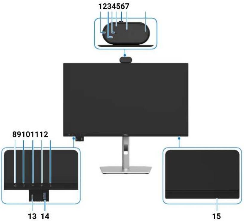
Figure 1. Front view of the monitor
Table 1. Components and descriptions.
| Label Description Function | ||
| 1 | Microphones Monitor microphones (Mic). | |
| 2 | IR LED Indicator of infrared (IR). | |
| 3 | Webcam LED indicator Indicator of Webcam. It will light up in white when webcam is in use. | |
| 4 | IR Camera Supports the face recognition feature. | |
| 5 | Camera Shutter Close/Open Move left to close camera shutter. When closed, the camera will replace the image with a black pattern.Move right to open camera shutter. When opened, UC applications can open camera function to use the camera when it is needed.①NOTE:The close camera shutter is different from the disable 'Webcam & Presence Sensor' in OSD menu. Disabling 'Webcam & Presence Sensor' will turn off the whole webcam module, hence webcam and sensor will not appear in the system. | |
| 6 | RGB Camera | Transmits your image in a video conference. |
| 7 | Microphones Monitor microphones (Mic). | |
| 8 | Teams button & LED LED will light in static white when Microsoft Teams® is signed in and running.LED will blink when there is a Teams notification.Short press on the button to bring up Teams and open notification. Ensure that the Teams application is signed in and is already running at the background.1 NOTE: For the Teams button to work, ensure that the Teams account is provisioned/setup as 'Teams Only' mode. The tenant administrator should enable the account to 'Teams Only' mode.1 NOTE: Teams button will only work with Teams application in 'Teams Only' mode. Setting might vary in corporate environment, resulting in Teams button not working on the monitor. Please check with your system administrator. | |
| 9 | Hookswitch & LED LED will blink in green when there is an incoming Teams call.LED will light up in static green during Teams call.Short press to answer/end call.Long press to reject incoming call. | |
| 10 | Volume down & LED Short press for 2 unit volume decrement.Long press for continuous volume decrement. | |
| 11 | Volume up & LED Short press for 2 unit volume increment.Long press for continuous volume increment. | |
| 12 | Microphone mute & LED Press to mute and unmute microphone.LED will light up in static red when mic is muted.LED will go dark when mic is enabled/unmuted. | |
| 13 | USB-C 5Gbps downstream port Connect your USB device.The USB-C port supports 5 V/3 A.i NOTE: To use this port for USB data transfer, you must connect one of the following cables from your computer to the monitor:• USB-C to C cable or USB Type-A to Type-C cable (Rear side USB-C upstream port)• USB Type-A to Type-B cable (Rear side USB Type-B upstream port) | |
| 14 | USB Type-A 5Gbps downstream port Connect your USB device.The USB Type-A port supports BC1.2 5 V/1.5 A typical (2 A max) power charging (10W).i NOTE: To use this port for USB data transfer, you must connect one of the following cables from your computer to the monitor:• USB-C to C cable or USB Type-A to Type-C cable (Rear side USB-C upstream port)• USB Type-A to Type-B cable (Rear side USB Type-B upstream port) | |
| 15 | Power LED indicator Solid white light indicates the monitor is turned on and functioning normally.Blinking white light indicates the monitor is in Standby Mode. | |
Back view
natural_image
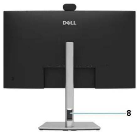
Front view of a Dell computer monitor with a vertical stand and labeled screen (no text or symbols on the device itself)Figure 2. Back view of the monitor
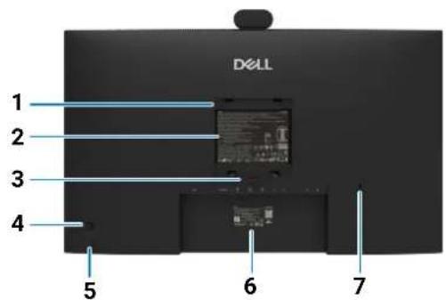
Table 2. Components and descriptions.
| Label Description Function | ||
| 1 | VESA mounting 4 holes(100 mm x 100 mm - behind attached VESA cover) | Wall mount monitor using VESA-compatible wall mount kit. |
| 2 | Regulatory information label Lists the regulatory approvals. | |
| 3 | Stand release button Releases the stand from the monitor. | |
| 4 | Joystick Use it to control the OSD menu. | |
| 5 | Power On/Off button To turn the monitor on or off. | |
| 6 | Regulatory label (including Mac address, MyDell QR code, serial number, and Service Tag label) | Refer to this label if you need to contact Dell for technical support. The Service Tag is a unique alphanumeric identifier that enables Dell service technicians to identify the hardware components in your computer and access warranty information. |
| 7 | Security lock slot Secures the monitor with a security cable lock (sold separately). | |
| 8 | Cable-management slot Use to organize cables by routing them through the slot. | |
Bottom view (P2426HEB/P2726DEB)
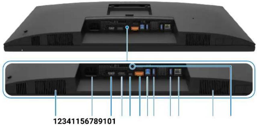
Figure 3. Bottom view of the monitor
Table 3. Components and descriptions.
| Label Description Function | ||
| 1 | Built-in speakers To output the sound from audio input. | |
| 2 | [6480]Power connector | Connects the power cable. |
| 3 |  HDMI port HDMI port | Connects your computer with the HDMI cable. |
| 4 | [IMAGE]DisplayPort (in) | Connects your computer with the DisplayPort cable. |
| 5 | [1960]USB-C 5Gbps upstream port(Video + Data) | Connect to your computer using the USB-C cable.P2426HEB: The USB-C port offers the fastest transfer rate and the alternate mode with a DP 1.4 support with a maximum resolution of 1920 x 1080 at 120 Hz, PD 20 V/4.5 A, 15 V/3 A, 9 V/3 A, 5 V/3 A.P2726DEB: The USB-C port offers the fastest transfer rate and the alternate mode with a DP 1.4 support with a maximum resolution of 2560 x 1440 at 100 Hz, PD 20 V/4.5 A, 15 V/3 A, 9 V/3 A, 5 V/3 A.⓪ NOTE: USB-C is not supported on Windows versions older than Windows 10. |
| 6 | [6477]DisplayPort (out) | DP output for MST (multi-stream transport) capable monitor. To enable MST, refer to instruction on section “Connecting the monitor for DisplayPort Multi-Stream Transport (MST) function”.⓫ NOTE: Remove the rubber plug when using DP out connector. |
| 7 | [40XY]USB Type-B upstream port | Connect the USB cable that comes with your monitor to the computer. Once this cable is connected, you can use the USB downstream connectors on the monitor. |
| 8,9 | [3YXO]Two USB Type-A 5Gbps downstream ports | Connect your USB device. You can use these ports only after you have connected the USB cable from the computer to the monitor.⓹ NOTE: To avoid signal interference, when a wireless USB device has been connected to a USB downstream port, it is NOT recommended to connect any other USB devices to the adjacent port(s). |
| 10 | [9544]RJ45 connector | Connect to Internet. You can surf the Internet using RJ45 only after you have connected the USB cable (Type-A to Type-B or USB-C to C) from the computer to the monitor. |
| 11 | Stand lock | Lock the stand to the monitor using a M3 x 6 mm screw (screw not included). |
Bottom view (P3426WEB)
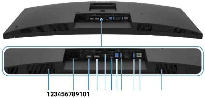
Figure 4. Bottom view of the monitor
Table 4. Components and descriptions.
| Label Description Function | ||
| 1 | Built-in speakers To output the sound from audio input. | |
| 2 | Power connector | Connects the power cable. |
| 3 | HDMI HDMI port | Connects your computer with the HDMI cable. |
| 4 | D DisplayPort (in) | Connects your computer with the DisplayPort cable. |
| 5 | Stand lock Lock the stand to the monitor using a M3 x 6 mm screw (screw not included). | |
| 6 | D←90W USB-C 5Gbps upstream port(Video + Data) | Connect to your computer using the USB-C cable.The USB-C port offers the fastest transfer rate and the alternate mode with a DP 1.4 support with a maximum resolution of 3440 x 1440 at 100 Hz, PD 20 V/4.5 A, 15 V/3 A, 9 V/3 A, 5 V/3 A. i NOTE: USB-C is not supported on Windows versions older than Windows 10. |
| 7 | USB Type-B upstream port | Connect the USB cable that comes with your monitor to the computer. Once this cable is connected, you can use the USB downstream connectors on the monitor. |
| 8,9 | Two USB Type-A 5Gbps downstream ports | Connect your USB device. You can use these ports only after you have connected the USB cable from the computer to the monitor. i NOTE: To avoid signal interference, when a wireless USB device has been connected to a USB downstream port, it is NOT recommended to connect any other USB devices to the adjacent port(s). |
| 10 | RJ45 connector | Connect to Internet. You can surf the Internet using RJ45 only after you have connected the USB cable (Type-A to Type-B or USB-C to C) from the computer to the monitor. |
Major components of P2426HEB/P2726DEB/P3426WEB monitor
The following image shows the major components of P2426HEB/P2726DEB/P3426WEB.
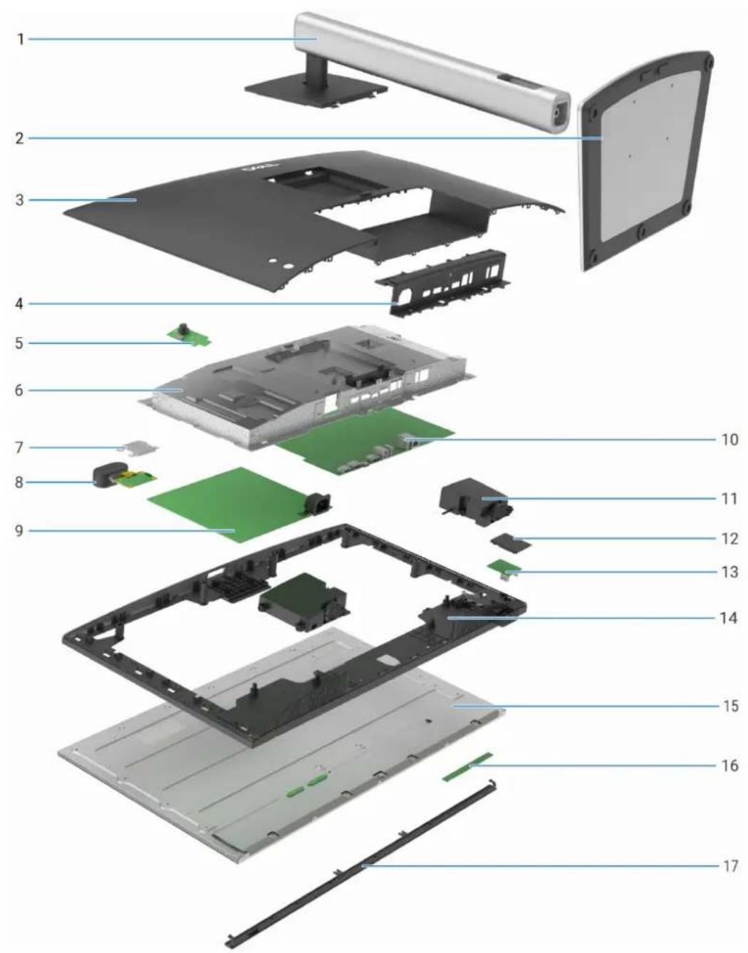
Figure 5. Major components of the P2426HEB/P2726DEB/P3426WEB monitor
Table 5. Major components
| Callout Description | |
| 1 Stand riser | |
| 2 Stand base | |
| 3 Back cover | |
| 4 I/O cover | |
| 5 Keypad board | |
| 6 Main chassis | |
| 7 Shielding cover | |
| 8 Camera module | |
| 9 Power board | |
| 10 Main board | |
| 11 Speaker | |
| 12 QAP cover | |
| 13 USB board | |
| 14 Middle frame | |
| 15 Display panel | |
| 16 Touch board | |
| 17 Front trim |
Wiring connectivity diagram
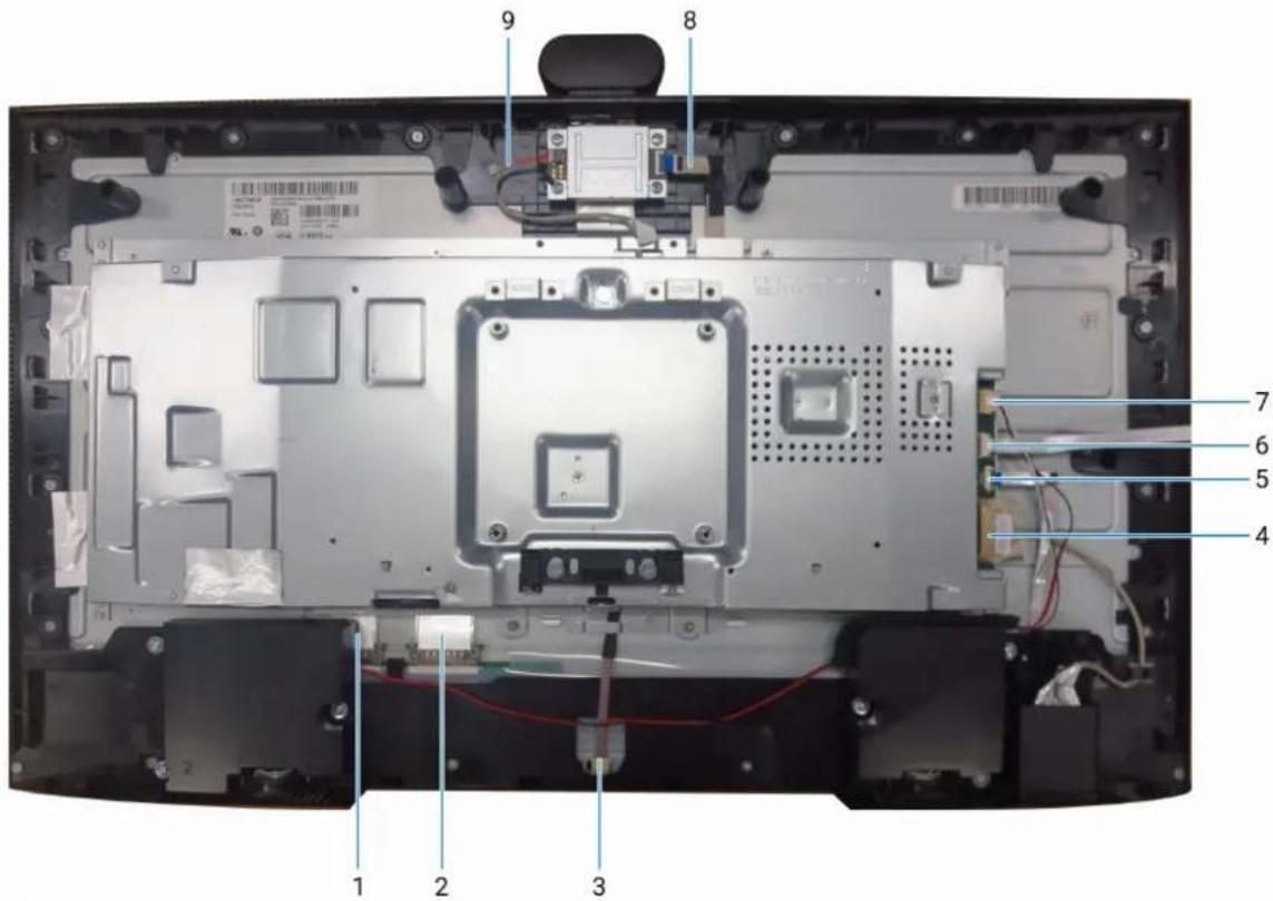
Figure 6. Wiring connectivity diagram
Table 6. Components and descriptions.
| Callout Description | |
| 1 LVDS cable 1 | |
| 2 LVDS cable 2 (only for P2726DEB) | |
| 3 Lightbar cable | |
| 4 USB cable | |
| 5 Touch cable | |
| 6 Keypad cable | |
| 7 Speaker cable | |
| 8 FFC cable | |
| 9 ISP connect cable | |
Connecting your monitor
WARNING: Before you begin any of the procedures in this section, follow the Safety instructions.
WARNING: For your safety, be sure that the grounded power outlet you plug the power cord into easily accessible to operator and located as close to the equipment as possible. To disconnect power from the equipment, unplug the power cord from the power outlet by grasping the plug firmly. Never pull on the cord.
NOTE: Dell monitors are designed to work optimally with the Dell-supplied cables inside the box. Dell does not guarantee the video quality and performance if non-Dell cables are used.
NOTE: Route the cables through the cable-management slot before connecting them.
NOTE: Do not connect all the cables to the computer at the same time.
NOTE: The images are for the purpose of illustration only. The appearance of the computer may vary.
To connect your monitor to the computer:
- Turn off your computer and disconnect the power cable.
- Connect the HDMI/DisplayPort/Thunderbolt 4 cable from your monitor to the computer.
△ CAUTION: Before using the monitor, it is recommended to fasten the stand riser to a wall using cable tie or a cord that can support the weight of monitor in order to prevent the monitor from falling.
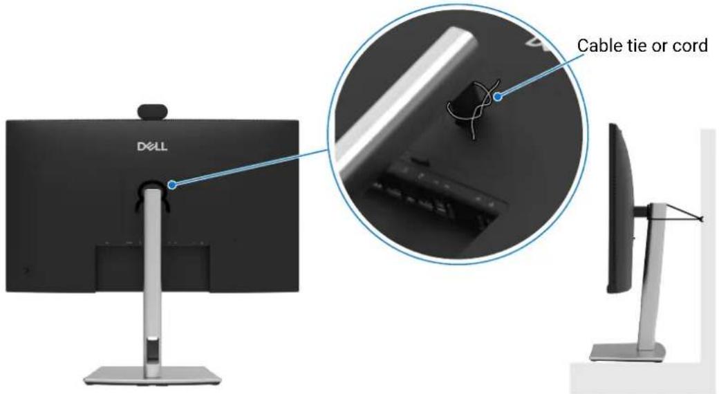
Figure 7. Prevent the monitor from falling
- Turn on your monitor.
- Select the correct input source from the OSD Menu on your monitor and then turn on your computer.
NOTE: The default setting in P2426HEB/P2726DEB/P3426WEB is DisplayPort 1.4. A DisplayPort 1.1 graphic card may not display normally. See product specific problems - No image when using DP connection to the computer to change the default setting.
NOTE: Remove the rubber plug when using DisplayPort (out).
Connecting the HDMI cable (optional)
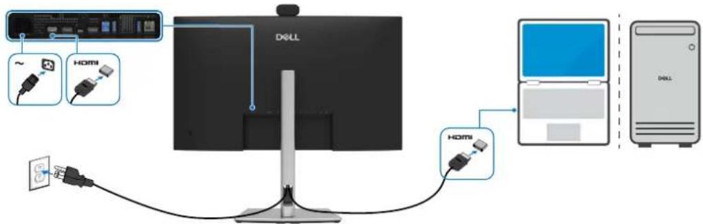
Figure 8. Connecting the HDMI cable
Connecting the DisplayPort cable
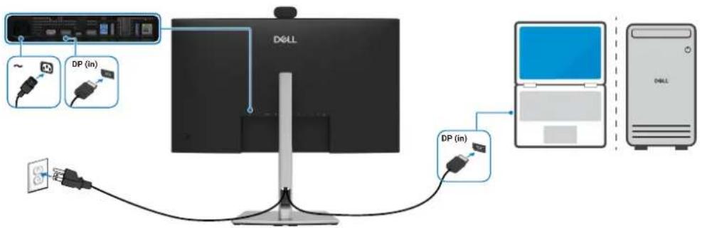
Figure 9. Connecting the DisplayPort cable
Connecting the monitor for DisplayPort Multi-Stream Transport (MST) function (P2426HEB/P2726DEB only)
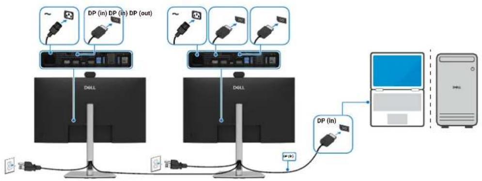
Figure 10. Connecting the monitor for DisplayPort Multi-Stream Transport (MST) function
NOTE: Supports the DisplayPort MST feature. To use this feature, your computer graphic card must be certified to at least DP 1.2 with MST option.
Connecting the USB Type-A to Type-B cable
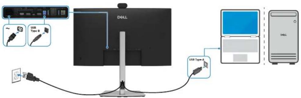
Figure 11. Connecting the USB Type-A to Type-B cable
NOTE: This connection supports data only and does not transmit video. An additional video connection for display is needed.
Connecting the USB-C to C cable
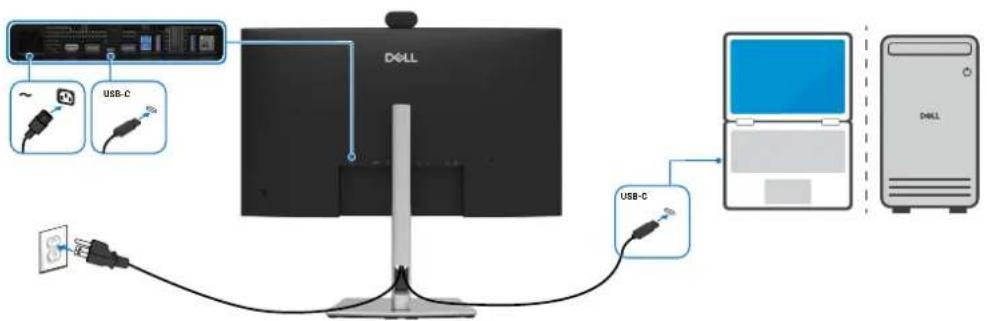
Figure 12. Connecting the USB-C to C cable
The USB-C port on your monitor:
- Can be used as USB-C, DisplayPort 1.4 alternatively.
• Supports USB Power Delivery (PD), with profiles up to 90 W.
NOTE: Regardless of the power requirement/actual power consumption of your laptop, or the remaining power runtime in your battery, the Dell monitor is designed to supply power delivery of up to 90 W to your laptop.
| Rated power (on laptops that have USB-C with Power Delivery) | Maximum charging power |
| 45 W 45 W | |
| 65 W 65 W | |
| 90 W 90 W | |
| 130 W Not supported |
Connecting the USB Type-A to Type-C cable (Optional)
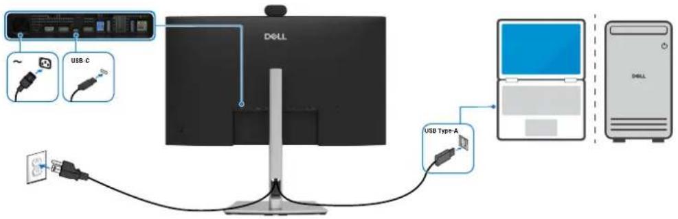
Figure 13. Connecting the USB Type-A to Type-C cable
NOTE: This connection supports data only and does not transmit video. An additional video connection for display is needed.
NOTE: USB Type-A to Type-C cable is not the standard in-box accessory.
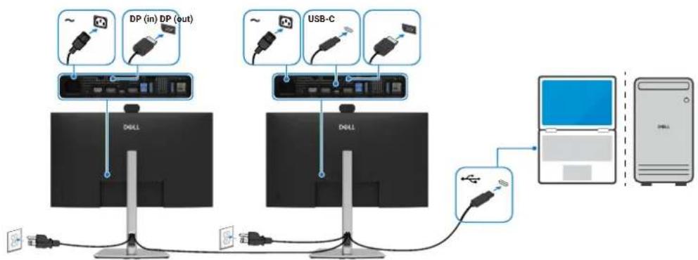
Connecting the monitor for USB-C Multi-Stream Transport (MST) function (P2426HEB/P2726DEB only)
flowchart
graph TD
    A["Desktop Tower"] -->|USB cable to USB cable via USB cable| B["Server"]
    B --> C["USB-C port"]
    C --> D["Desktop Tower"]
    D --> E["USB cable to USB cable via USB cable"]
    E --> F["Desktop Tower"]
    F --> G["USB cable to USB cable via USB cable via USB cable"]
    G --> H["Desktop Tower"]
    H --> I["USB cable to USB cable via USB cable via USB cable"]
    I --> J["Desktop Tower"]
    J --> K["USB cable to USB cable via USB cable via USB cable"]
    K --> L["Desktop Tower"]
    L --> M["USB cable to USB cable via USB cable via USB cable"]
    M --> N["Desktop Tower"]
Figure 14. Connecting the Monitor for USB-C Multi-Stream Transport (MST) function
NOTE: The maximum number of supported P2426HEB/P2726DEB via MST is subjected to the bandwidth of the USB-C source. Please refer to Product specific problems – No image when using USB-C MST.
Connecting the monitor for RJ45 cable (optional)
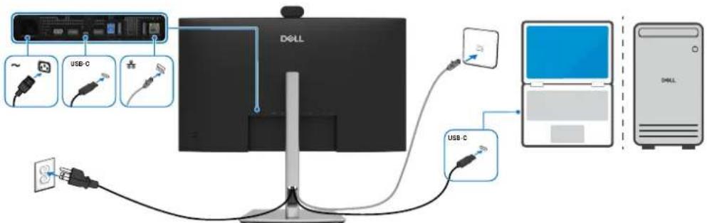
Figure 15. Connecting the monitor for RJ45 cable
Disassembly and reassembly
CAUTION: The information in this section is intended for authorized service technicians in the EMEA region. Dell prohibits users from disassembling the monitor, and any damage caused by unauthorized servicing will not be covered under the warranty.
Recommended tools
- Screwdriver Phillips screwdriver #0
- Screwdriver Phillips screwdriver #2
- Penknife
Screw list
NOTE: When removing screws from a component, it is recommended to note the screw type, the quantity of screws, and then place them in a screw storage box. This is to ensure that the correct number of screws and correct screw type is restored when the component is replaced.
NOTE: Some monitors have magnetic surfaces. Ensure that the screws are not left attached to such surfaces when replacing a component.
NOTE: Screw color may vary depending on the configuration ordered.
Table 7. Components and descriptions.
| Component Screw type Quantity Screw image | |||
| Back cover | M4x10 4 |  | |
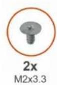
| Keypad board | M2x3.3 2 |  | |
| IO Cover | M3x3 2 |  | |
| USB board | M3x6 1 |  | |
| Speakers | M3x8 6 |  | |
| Camera module | M3x4.5 7 |  | |
| Main chassis | M3x3 4 |  | |
| Middle frame (P2426HEB) | M3x5 13 | [AGST] | |
| Middle frame (P2726DEB) | M3x5 17 |  | |
| Middle frame (P3426WEB) | M3x5 18 |  | |
| Front trim | M2x3.3 2 |  | |
| Power board groundwire | M4x8 1 |  | |
| Power board | M3x6 4 |  | |
| Main board | M3x6 3 |  | |
Stand
Removing the stand
Prerequisites
- Follow the procedure in Before working inside your monitor.
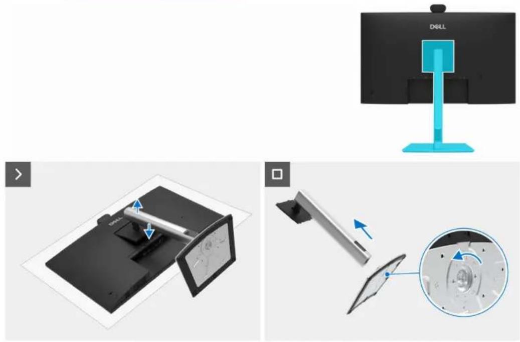
natural_image
Technical illustration showing a desktop monitor with a scroll and its internal components, alongside a monitor mounted on a stand (no text or symbols visible)Figure 16. Removing the stand
Steps
- Place the monitor on a soft cloth or cushion.
- Press and hold the stand-release button.
- Lift the stand up and away from the monitor.
- Open the screw handle at the bottom of the stand base, and turn it anti-clockwise to unlock the riser with base.
- Remove the stand riser from the stand base.
Installing the stand
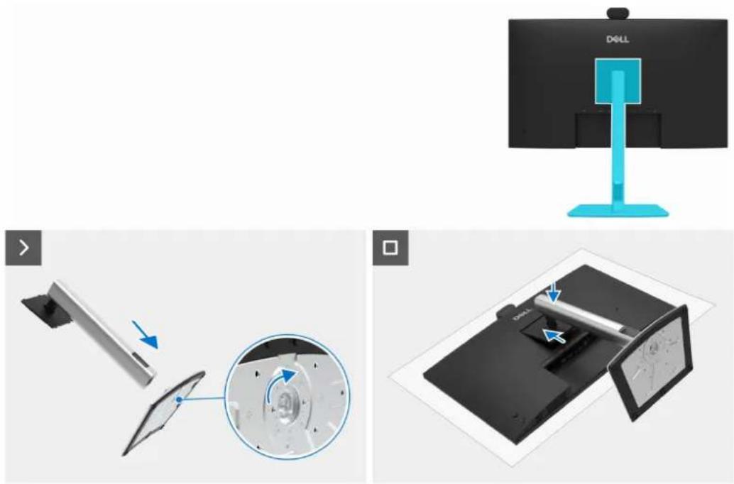
natural_image
Two-panel image showing a Dell monitor with a blue stand and its internal components, alongside a close-up of the device's screen (no text or symbols visible)Figure 17. Installing the stand
Steps
- Align the tabs on the stand base with the slots on the stand riser.
- Insert the stand riser on the stand base firmly.
- Open the screw handle at the bottom of the stand base, and rotate it clockwise to tighten the screw firmly.
- Close the screw handle.
- Align the stand assembly bracket to the monitor head.
- Insert the bracket towards monitor until it locks in place.
Next steps
- Follow the procedure in After working inside your monitor.
Back cover
Removing the back cover
Prerequisites
- Follow the procedure in Before working inside your monitor.
- Remove the stand.
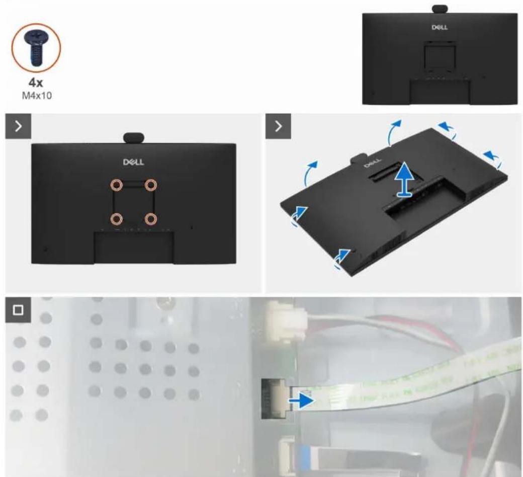
Figure 18. Removing the back cover
Steps
- Remove the four screws (M4x10) to release the back cover.
- Using both hands, gently pry the back cover off, starting from the top side, then moving to the left and right sides.
- Partially lift the back cover from the bottom edge.
- Disconnect the keypad cable from the connector on the main board.
- Remove the back cover from the display assembly.
Installing the back cover
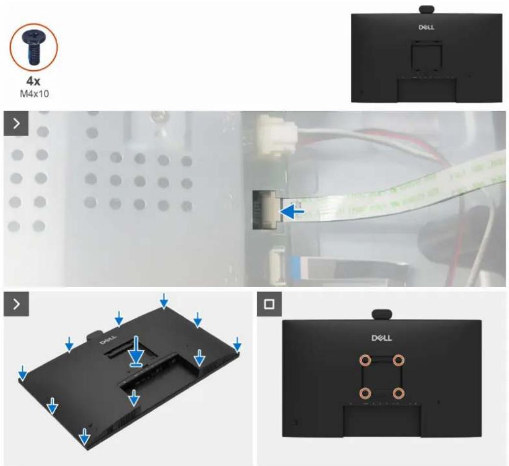
Figure 19. Installing the back cover
Steps
- Connect the keypad cable to the connector on the main board.
- Align the back cover with the main chassis, then press along the sides to snap the back cover into place.
- Replace the four screws (M4x10) to secure the back cover to the monitor.
Next steps
- Install the stand.
- Follow the procedure in After working inside your monitor.
Keypad board
Removing the keypad board
Prerequisites
- Follow the procedure in Before working inside your monitor.
- Remove the stand.
- Remove the back cover.
natural_image
Interior view of a mechanical or electronic component with no visible text, numbers, or symbols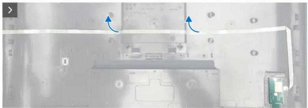
natural_image
Interior view of a computer monitor with visible circuit board and keyboard (no text or symbols)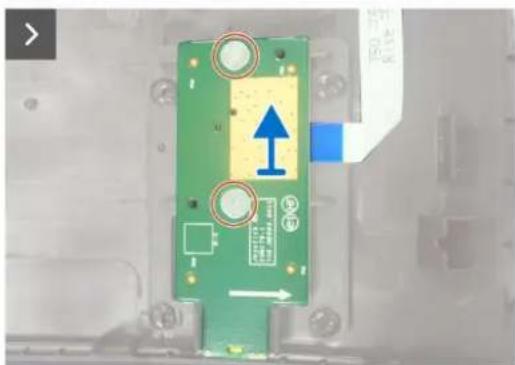
natural_image
Green printed circuit board with blue directional arrow and circular annotations (no readable text or symbols)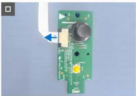
natural_image
Green printed circuit board with electronic components and a blue arrow pointing to a component (no readable text or symbols)Figure 20. Removing the keypad board
Steps
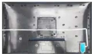
- Peel the double-sided tape that secures the keypad cable to the back cover.
- Remove the two screws (M2x3.3) that secure the keypad board to the back cover.
- Remove the keypad board from the pins on the back cover.
- Disconnect the keypad cable from the keypad board.
Installing the keypad board
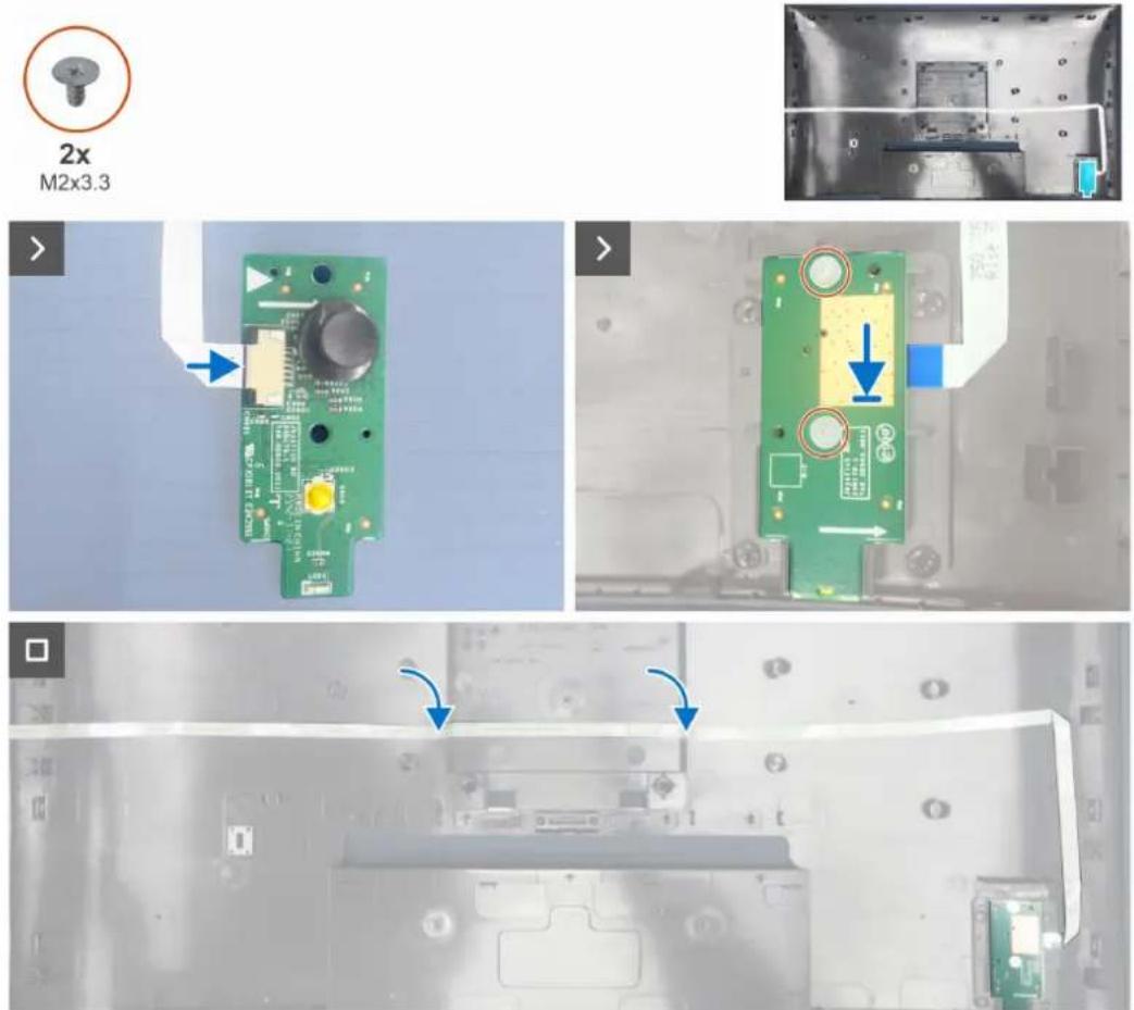
Figure 21. Installing the keypad board
Steps
- Connect the keypad cable to the keypad board.
- Align the holes on the keypad board with the screw holes on the back cover, and place it down.
- Replace the two screws (M2x3.3) that secure the keypad board to the back cover.
- Adhere the double-sided tape to secure the keypad cable to the back cover.
Next steps
- Install the back cover.
- Install the stand.
- Follow the procedure in After working inside your monitor.
I/O Cover
Removing the I/O cover
Prerequisites
- Follow the procedure in Before working inside your monitor.
- Remove the stand.
- Remove the back cover.
- Remove the keypad board.
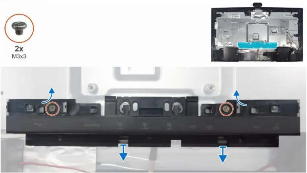
Figure 22. Removing the I/O cover
Steps
- Remove the two screws (M3x3) that secure the I/O cover to the main chassis.
- Lift and remove the I/O cover off the main chassis.
Installing the I/O Cover
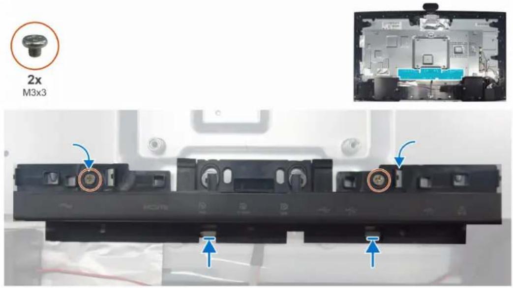
Figure 23. Installing the I/O cover
Steps
- Place the I/O cover on the main chassis.
- Align the screw holes on the I/O cover with the screw holes on the main chassis.
- Replace the two screws (M3x3) that secure the I/O cover to the main chassis.
Next steps
- Install the keypad board.
- Install the back cover.
- Install the stand.
- Follow the procedure in After working inside your monitor.
Speakers
Removing the speakers
Prerequisites
- Follow the procedure in Before working inside your monitor.
- Remove the stand.
- Remove the back cover.
- Remove the keypad board.
- Remove the 10 cover.
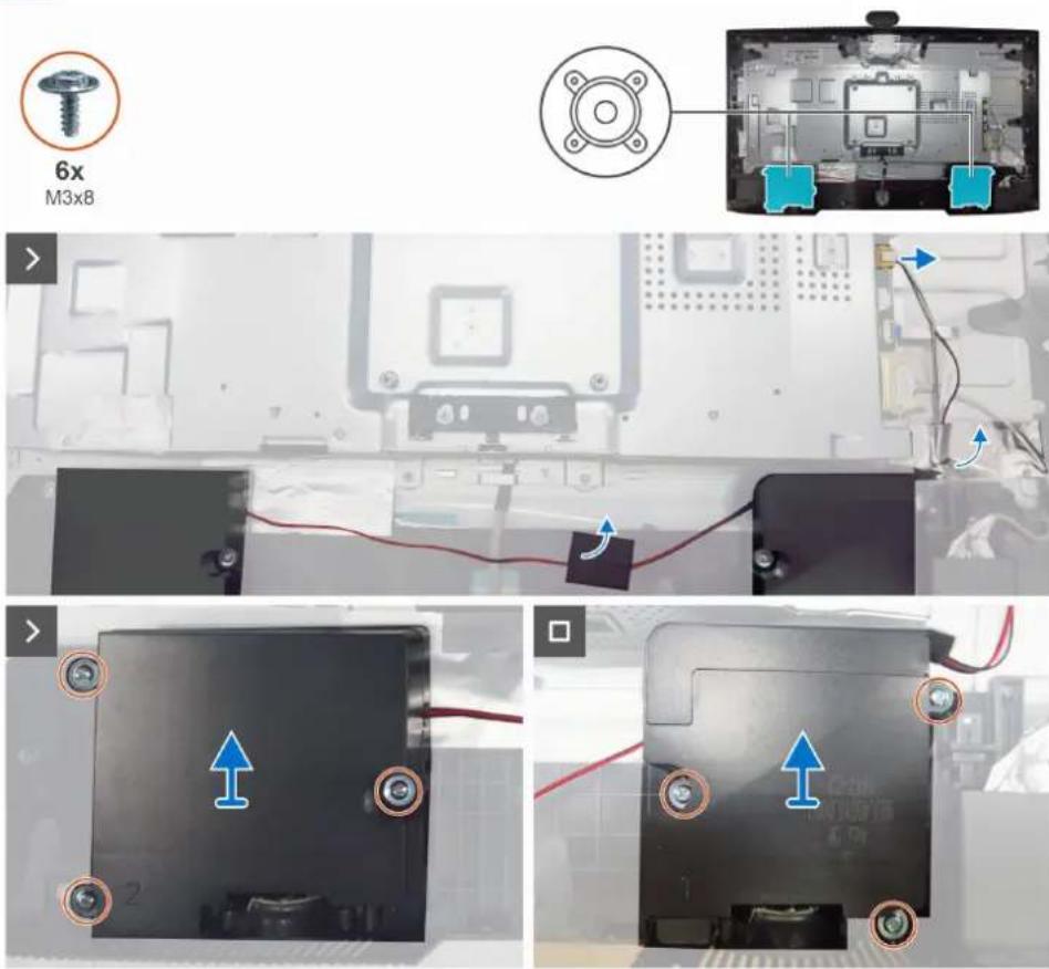
Figure 24. Removing the speakers
Steps
- Peel off the Aluminum foil and tape on the speaker cable.
- Disconnect the speaker cable from the connector on the main board.
- Remove the six screws (M3x8) that secure the two speakers to the middle frame.
- Remove the two speakers from the pins on the middle frame.
Installing the speakers
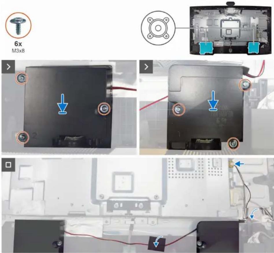
Figure 25. Installing the speakers
Steps
- Align the holes on the two speakers to the screw holes on the middle frame, and place it down.
- Replace the six screws (M3x8) that secure the two speakers to the middle frame.
- Connect the speaker cable to the connector on the main board.
- Adhere the tapes to secure the speakers cable to the display-assembly base.
Next steps
- Install the IO cover.
- Install the keypad board.
- Install the back cover.
- Install the stand.
- Follow the procedure in After working inside your monitor.
Main chassis
Removing the main chassis
Prerequisites
- Follow the procedure in Before working inside your monitor.
- Remove the stand.
- Remove the back cover.
- Remove the keypad board.
- Remove the 10 cover.
- Remove the speakers.

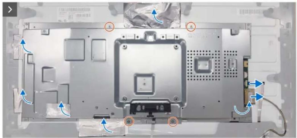
natural_image
Laptop front panel with visible internal components and blue directional arrows indicating movement or force (no text or symbols)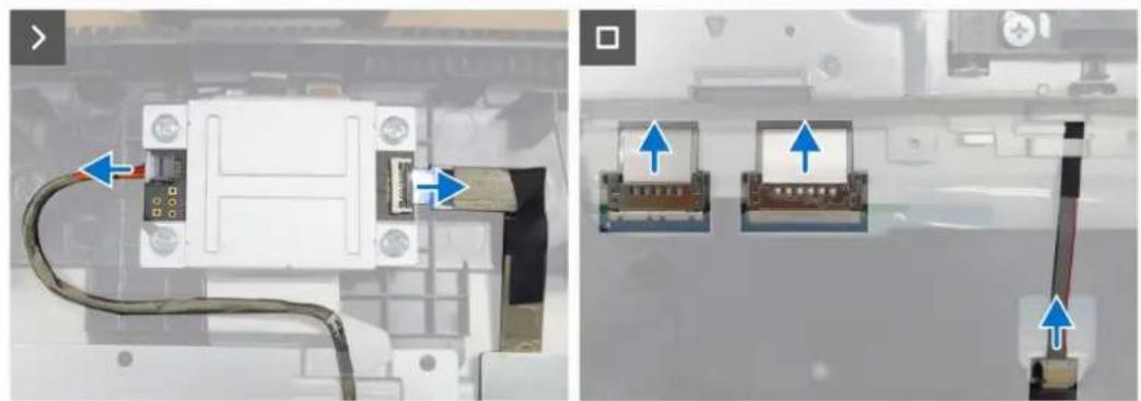
natural_image
Two-panel image showing a device with cable and connector, alongside two close-up views of the same electronic component (no text or symbols visible)Figure 26. Removing the main chassis
Steps
- Peel all the aluminum foil on the chassis.
- Remove the four screws (M3x3) that secure the main chassis to the display panel.
- Disconnect the FFC cable and ISP connect cable from the connectors on the ISP board.
- Disconnect the USB cable and touch cable from the connectors on the main board.
- Disconnect the lightbar cable and the LVDS cables from the connectors on the display panel.
- Remove the main chassis away from the display panel.
Installing the main chassis
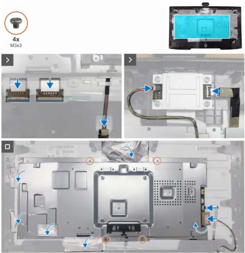
Figure 27. Installing the main chassis
Steps
- Align the holes on the main chassis with the screw holes on the display panel and place it down.
- Connect the the LVDS cables and lightbar cable to the connectors on the display panel.
- Connect the USB cable and touch cable to the connectors on the main board.
- Connect the FFC cable and ISP connect cable to the connectors on the ISP board.
- Replace the four screws (M3x3) to secure the main chassis with the display panel.
- Adhere all the aluminum foil on the main chassis.
Next steps
- Install the speakers.
- Install the 10 cover.
- Install the keypad board.
- Install the back cover.
-
Install the stand.
-
Follow the procedure in After working inside your monitor.
USB Board
Removing the USB board
Prerequisites
- Follow the procedure in Before working inside your monitor.
- Remove the stand.
- Remove the back cover.
- Remove the keypad board.
- Remove the 10 cover.
- Remove the speakers.
- Remove the main chassis.
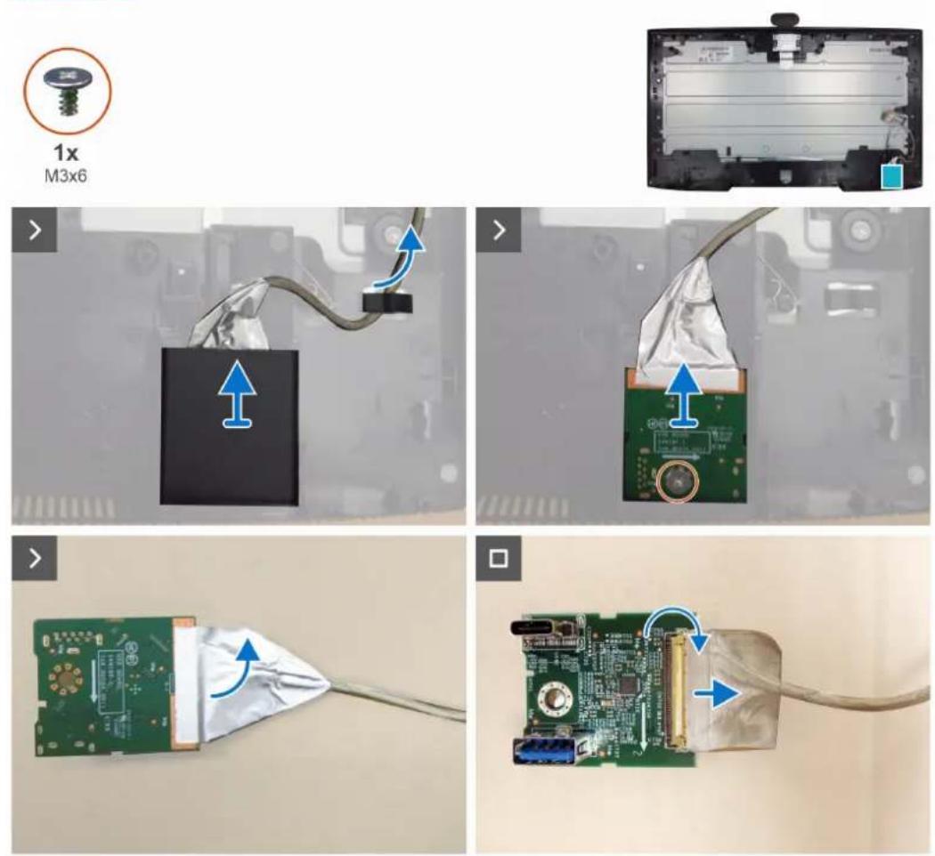
Figure 28. Removing the USB board
Steps
- Release the USB cable from the slot on the middle frame.
- Pry the top cover of the QAP to remove it.
- Remove the screw (M3x6) that secures the USB board to the middle frame.
- Remove the USB board from middle frame.
- Lift the locks and pull out the USB cable from the USB board.
Installing the USB board
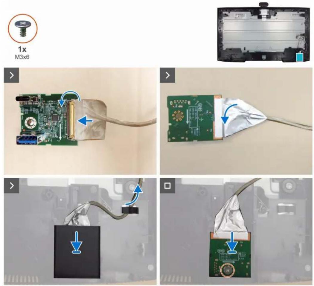
Figure 29. Installing the USB board
Steps
- Connect the USB cable to the USB board and lock it.
- Replace the USB board to the middle frame.
- Replace the screw (M3x6) that secures the USB board to the middle frame.
- Replace the top cover of the QAP
- Route the USB cable through the slot on the middle frame.
Next steps
- Install the main chassis.
- Install the speakers.
- Install the 10 cover.
- Install the keypad board.
- Install the back cover.
-
Install the stand.
-
Follow the procedure in After working inside your monitor.
Camera module
Removing the camera module
Prerequisites
- Follow the procedure in Before working inside your monitor.
- Remove the stand.
- Remove the back cover.
- Remove the keypad board.
- Remove the 10 cover.
- Remove the speakers.
- Remove the main chassis.
- Remove the USB board.
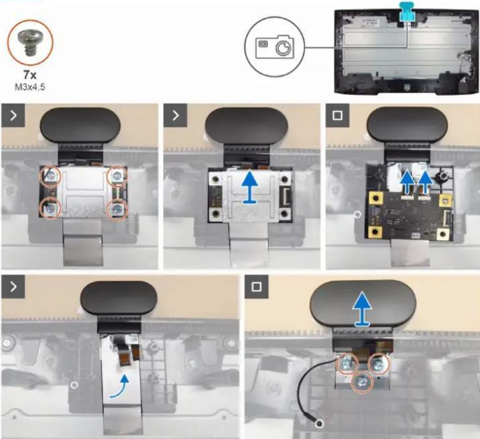
Figure 30. Removing the camera module
Steps
- Remove the four screws (M3x4.5) that secure the shielding cover to the middle frame.
- Remove the shielding cover.
- Disconnect the two camera cables from the connectors on the ISP board.
- Peel the aluminum foil from the camera module. (P2726DEB and P3426WEB)
- Remove the three screws (M3x4.5) that secure the camera module to the middle frame.
- Remove the camera module from the middle frame.
Installing the camera module
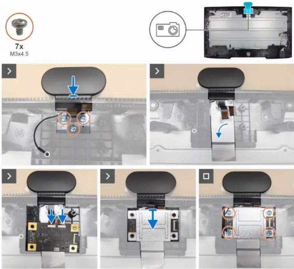
Figure 31. Installing the camera module
Steps
- Replace the camera module to the middle frame.
- Replace the three screws (M3x4.5) that secure the camera module to the middle frame.
- Adhere a aluminium foil on the camera module. (P2726DEB and P3426WEB)
- Connect the camera cables to the connectors on the camera board.
- Align the screw holes on the shielding cover to the screws holes on the camera board.
- Replace the four screws (M3x4.5) that secure the shilding cover, grounding wire and camera board to the middle frame.
Next steps
- Install the USB board.
- Install the main chassis.
- Install the speakers.
- Install the IO cover.
- Install the keypad board.
- Install the back cover.
-
Install the stand.
-
Follow the procedure in After working inside your monitor.
Middle frame
Removing the middle frame
Prerequisites
- Follow the procedure in Before working inside your monitor.
- Remove the stand.
- Remove the back cover.
- Remove the keypad board.
- Remove the 10 cover.
- Remove the speakers.
- Remove the main chassis.
- Remove the USB board.
- Remove the camera module.
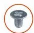
17x
M3×5
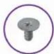
2x
M2x3.3
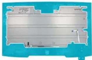
natural_image
3D rendering of a blue plastic enclosure with internal structure (no text or symbols visible)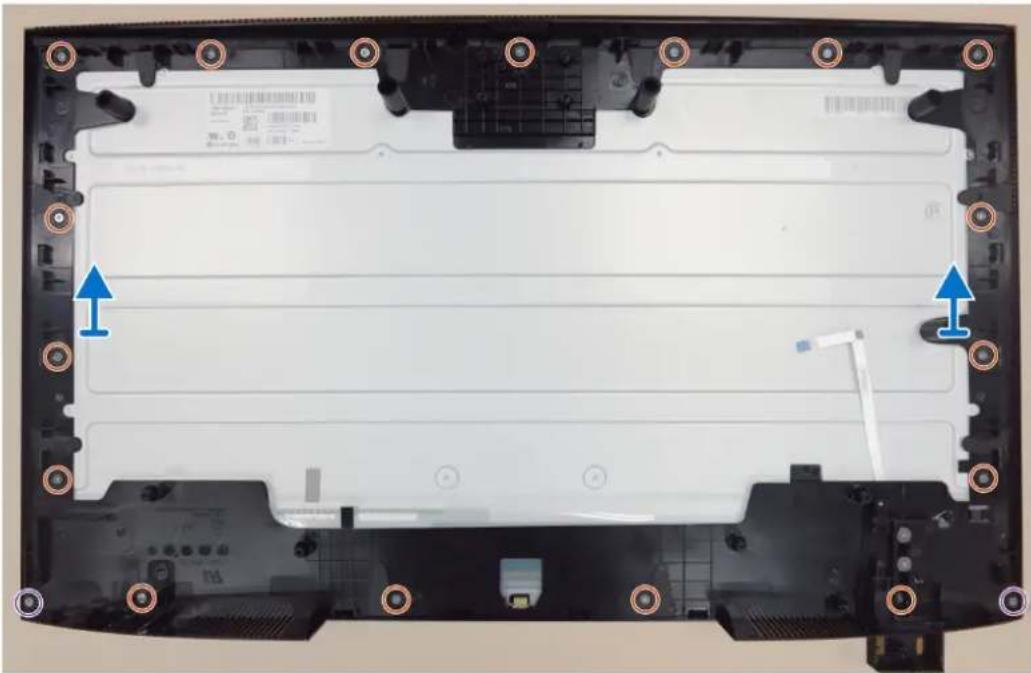
natural_image
Top-down view of a laptop chassis showing front panel, rear panel, and internal components (no text or symbols visible)Figure 32. Removing the middle frame
Steps
- Remove the thirteen screws (M3x5) that secure the middle frame to the display panel. (P2426HEB)
- Remove the seventeen screws (M3x5) that secure the middle frame to the display panel. (P2726HEB)
- Remove the eighteen screws (M3x5) that secure the middle frame to the display panel. (P3426WEB)
- Remove the two screws (M2x3.3) that secure the middle frame to the front trim.
- Lift and remove the middle frame away from the display panel.
Installing the middle frame
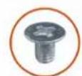
17x
M3x5
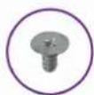
2x
M2x3.3
natural_image
3D rendering of a metallic battery pack with internal structure and mounting bracket (no text or symbols visible)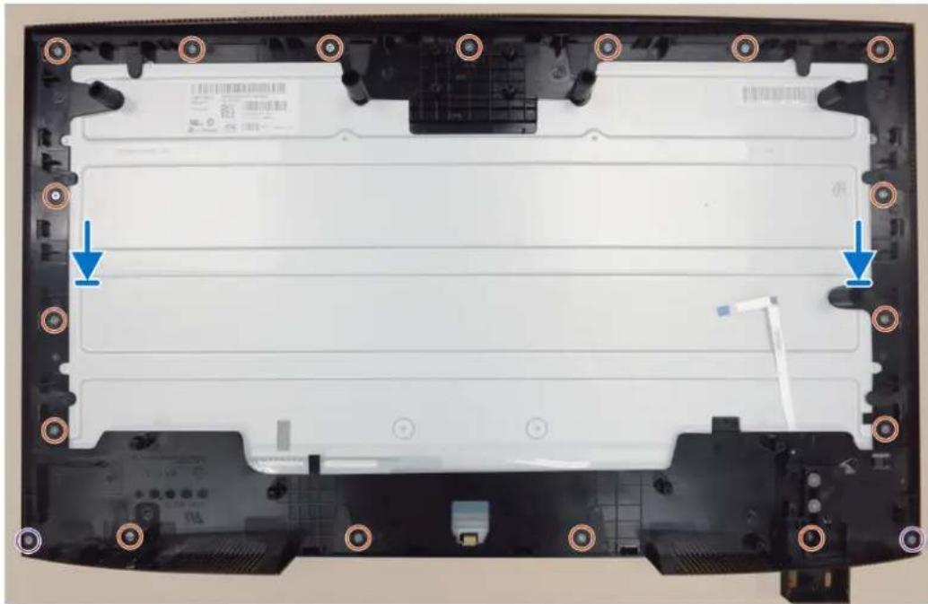
natural_image
Top-down view of a laptop back panel showing internal components and mounting holes (no text or symbols visible)Figure 33. Installing the middle frame
Steps
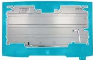
- Align and place the middle frame on the display panel.
- Replace the two screws (M2x3.3) that secure the middle frame to the front trim.
- Replace the thirteen screws (M3x5) that secure the middle frame to the display panel. (P2426HEB)
- Replace the seventeen screws (M3x5) that secure the middle frame to the display panel. (P2726DEB)
- Replace the eighteen screws (M3x5) that secure the middle frame to the display panel. (P3426WEB)
Next steps
- Install the camera module.
- Install the USB board.
- Install the main chassis.
- Install the speakers.
- Install the IO cover.
- Install the keypad board.
- Install the back cover.
-
Install the stand.
-
Follow the procedure in After working inside your monitor.
Front trim and touch board
Removing the front trim and the touch board
Prerequisites
- Follow the procedure in Before working inside your monitor.
- Remove the stand.
- Remove the back cover.
- Remove the keypad board.
- Remove the 10 cover.
- Remove the speakers.
- Remove the main chassis.
- Remove the USB board.
- Remove the camera module.
- Remove the middle frame.
natural_image
Three-panel photo showing a laptop with visible circuit board, cable, and cable stack, and a close-up of the internal battery cover (no text or symbols)Figure 34. Removing the front trim and the touch board
Steps
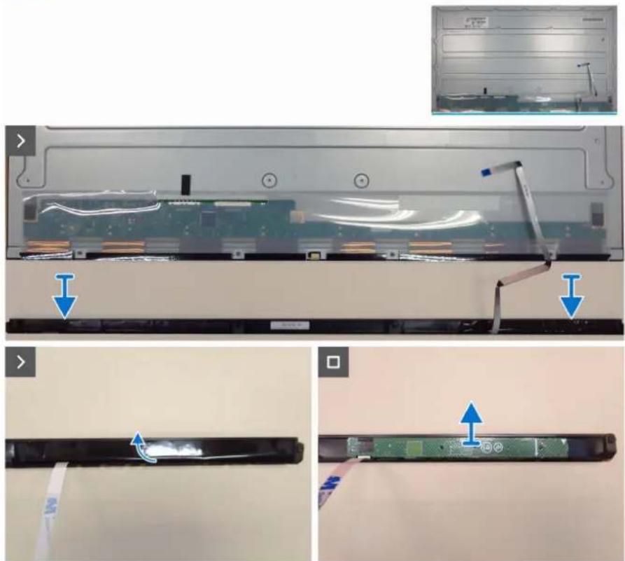
- Lift up the display panel and remove the front trim.
- Peel the mylar tape on the touch board.
- Remove the LED board from the front trim.
Installing the front trim and the touch board
Steps
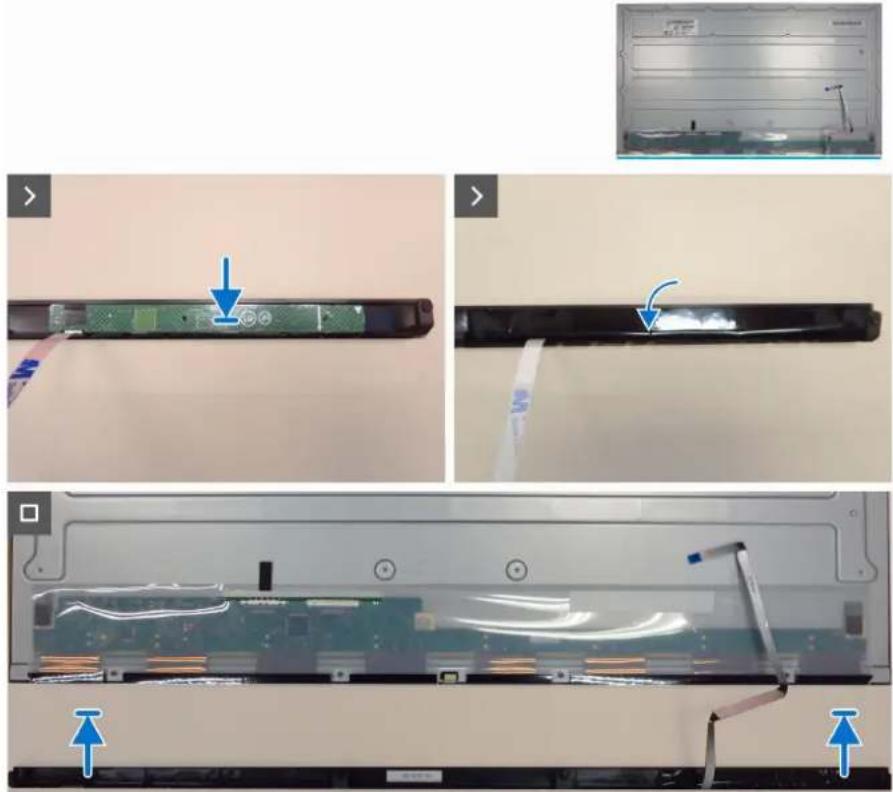
- Align the holes of the touch board with the pins on the front trim and paste it.
- Adhere a mylar tape to cover the touch board.
- Lift up the display panel and replace the front trim to the display panel.
natural_image
Three-panel photo showing a computer monitor with an open circuit board and cable, annotated with blue arrows indicating features (no text or symbols present)Figure 35. Installing the front trim and the touch board
Next steps
- Install the middle frame.
- Install the camera module.
- Install the USB board.
- Install the main chassis.
- Install the speakers.
- Install the 10 cover.
- Install the keypad board.
- Install the back cover.
-
Install the stand.
-
Follow the procedure in After working inside your monitor.
Main board
Removing the main board
Prerequisites
- Follow the procedure in Before working inside your monitor.
- Remove the stand.
- Remove the back cover.
- Remove the keypad board.
- Remove the 10 cover.
- Remove the speakers.
- Remove the main chassis.
- Remove the USB board.
- Remove the camera module.
- Remove the middle frame.
- Remove the front trim and touch board.
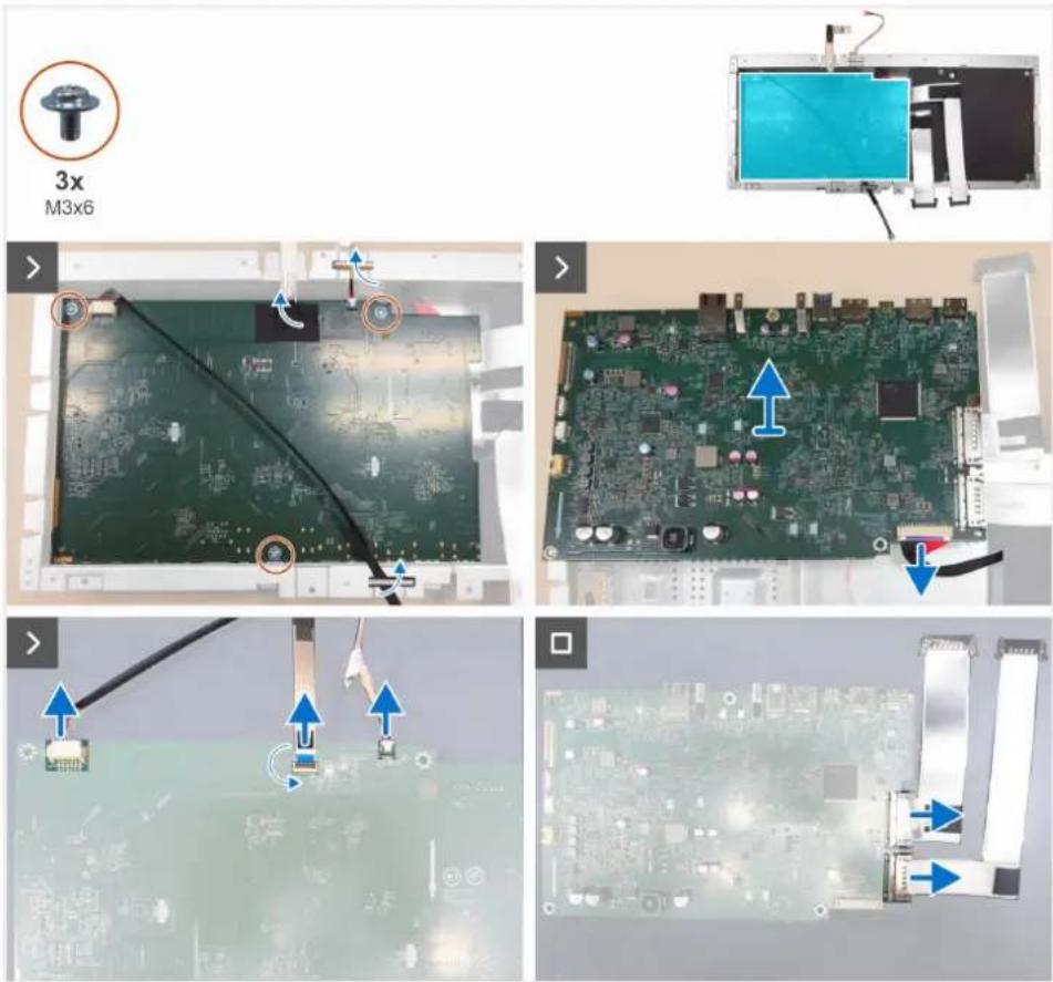
Figure 36. Removing the main board
Steps
- Unroute the lightbar cable and ISP connect cable from the routing guides on the main chassis.
- Peel the tape on the FFC connector.
- Remove the three screws (M3x6) that secure the main board to the main chassis.
- Turn over the main board and disconnect the power cable from the connector on the main board.
-
Remove the main board from the main chassis.
-
Disconnect the FFC cable, ISP connect cable and two LVDS cables (only for P2726DEV) from the connectors on the main board.
Installing the main board
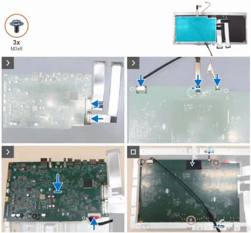
Figure 37. Installing the main board
Steps
- Connect the two LVDS cables (only for P2726DEV), FFC cable and ISP connect cable to the connectors on the main board.
- Connect the power cable to the main board.
- Turn over the main board and align the screw holes on the main board to the screw holes on the main chassis, and place it down.
- Replace the three screws (M3x6) to secure the main board to the main chassis.
- Adhere a tape to cover the ISP connector.
- Route the lightbar cable and ISP connect cable through the routing guides on the main chassis.
Next steps
- Install the front trim and touch board.
- Install the middle frame.
- Install the camera module.
- Install the USB board.
- Install the main chassis.
- Install the speakers.
- Install the IO cover.
- Install the keypad board.
- Install the back cover.
- Install the stand.
- Follow the procedure in After working inside your monitor.
Power board
Removing the power board
Prerequisites
- Follow the procedure in Before working inside your monitor.
- Remove the stand.
- Remove the back cover.
- Remove the keypad board.
- Remove the 10 cover.
- Remove the speakers.
- Remove the main chassis.
- Remove the USB board.
- Remove the camera module.
- Remove the middle frame.
- Remove the front trim and touch board.
- Remove the main board.
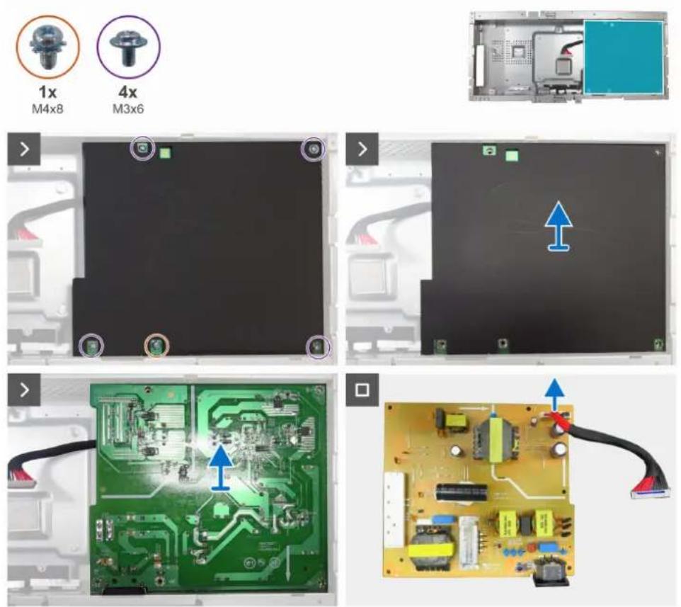
Figure 38. Removing the power board
Steps
- Remove the screw (M4x8) and the four screws (M3x6) that secure the Mylar sheet and power board to the main chassis.
- Remove the Mylar sheet from the slots in the main chassis.
- Remove the power board from the main chassis.
- Disconnect the power cable from the connector on the power board.
Installing the power board
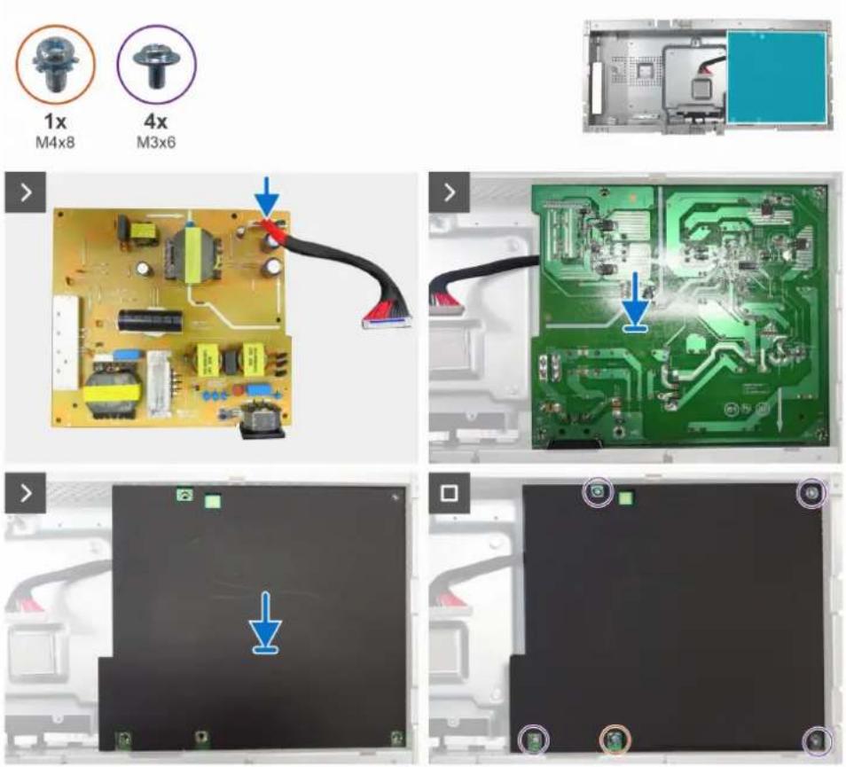
Figure 39. Installing the power board
Steps
- Connect the power cable to the connector on the power board.
- Align the screw holes on the power board with the screw holes on the main chassis, and place it down.
- Insert the Mylar sheet into the slot on the main chassis.
- Replace the one screw (M4x8) and the four screws (M3x6) that secure the power board to the main chassis.
Next steps
- Install the main board.
- Install the front trim and touch board.
- Install the middle frame.
- Install the camera module.
- Install the USB board.
- Install the main chassis.
- Install the speakers.
- Install the IO cover.
- Install the keypad board.
- Install the back cover.
- Install the stand.
- Follow the procedure in After working inside your monitor.
Troubleshooting
WARNING: Before you begin any of the procedures in this section, follow the Safety instructions.
Self-test
Your monitor provides a self-test feature that allows you to check whether your monitor is functioning properly. If your monitor and computer are properly connected but the monitor screen remains dark, run the monitor self-test by performing the following steps:
- Turn off both your computer and the monitor.
- Unplug the video cable from the back of the computer. To ensure proper Self-Test operation, remove all digital and the analog cables from the back of computer.
- Turn on the monitor.
If the monitor cannot sense a video signal and is working correctly, a dialog box appears on the screen (against a black background). While in self-test mode, the power LED remains white. Also, depending upon the selected input, one of the dialogs shown will continuously scroll through the screen.
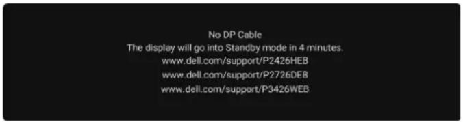
Figure 40. DP cable disconnected warning message
- This dialog box also appears during normal operation if the video cable is disconnected or damaged.
- Turn off your monitor and reconnect the video cable; then turn on both your computer and the monitor.
If your monitor screen still remains blank after performing the above steps, it indicates the monitor is functioning properly. Check the video controller and computer.
Built-in diagnostics
Your monitor includes a built-in diagnostic tool to help you identify whether the screen abnormality is due to an issue with the monitor itself or with your computer and video card.
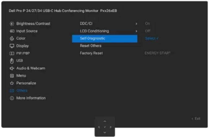
Figure 41. Built-in diagnostics
To run the built-in diagnostics:
- Ensure that the screen is clean (no dust particles on the surface of the screen).
- Select OSD items of Self-Diagnostics in Others feature.
- Press the Joystick button to start the diagnostics. A gray screen is displayed.
- Observe if the screen has any defects or abnormalities.
- Toggle the Joystick once again until a red screen is displayed.
- Observe if the screen has any defects or abnormalities.
- Repeat steps 5 and 6 until the screen displays green, blue, black, and white colors. Note any abnormalities or defects.
The test is complete when a text screen is displayed. To exit, toggle the Joystick control again.
If you do not detect any screen abnormalities upon using the built-in diagnostic tool, the monitor is functioning properly. Check the video card and computer.
Common problems
The following table contains general information about common monitor problems you might encounter and the possible solutions:
Table 8. Common problems
| Common symptoms What you experience Possible solutions | ||
| No video/power LED off No picture | ·Ensure that the video cable connecting the monitor and the computer is properly connected and secure.·Verify that the power outlet is functioning properly using any other electrical equipment.·Ensure that you have pressed the power button properly.·Ensure that the correct input source is selected in the Input Source menu. | |
| No video/power LED on No picture or no brightness | ·Increase brightness and contrast controls through OSD.·Perform monitor self-test feature check.·Check for bent or broken pins in the video cable connector.·Run theBuilt-in diagnostics.·Ensure that the correct input source is selected in the Input Source menu. | |
| Missing pixels LCD screen has spots ·Cycle power on-off. | ||
| ·A pixel that stays permanently off is a common defect in LCD technology.·For more information on Dell Monitor Quality and Pixel Policy, see Dell Display Pixel Guidelines. | ||
| Stuck-on pixels LCD screen has bright spots | ·Cycle power On-Off.·Pixel that is permanently off is a natural defect that can occur in LCD technology.·For more information on Dell Monitor Quality and Pixel Policy, see Dell Display Pixel Guidelines. | |
| Brightness problems Picture too dim or too bright | ·Reset the monitor to factory settings.·Adjust brightness and contrast controls through OSD. | |
| Safety-related issues Visible signs of smoke or sparks | ·Do not perform any troubleshooting steps.·Contact Dell immediately. | |
| Intermittent problems Monitor malfunctions on and off | ·Ensure that the video cable connecting the monitor to the computer is connected properly and is secure.·Reset the monitor to factory settings.·Perform monitor self-test feature check to determine if the intermittent problem occurs in self-test mode. | |
| Missing color Picture missing color ·Perform a monitor self-test. | ||
| ·Ensure that the video cable connecting the monitor to the computer is connected properly and is secure.·Check for bent or broken pins in the video cable connector. | ||
| Wrong color | Picture color not good | ·Try different Preset Modes in Color settings OSD.·Adjust R/G/B value under Custom Color in the Color menu OSD.·Change the Input Color Format to RGB or YCbCr in the Color settings OSD.·Run theBuilt-in diagnostics. |
| Image retention from a static image left on the monitor for a long period of time | Faint shadow from the static image displayed appears on the screen | ·Set the screen to turn off after a few minutes of screen idle time. These can be adjusted in the Windows Power Options or Mac Energy Saver setting.·Alternatively, use a dynamically changing screensaver. |
| Mic/Webcam does not work | ·USB cable not plug in or not select the correct USB source·Not set the monitor Mic/webcam as the default device | ·Plug in the USB Cable (Type-A to Type-B or Type-C to Type-C), and if you connect both USB-C port and USB Type-B port, switch the USB source in the OSD menu.·Select the monitor Mic/webcam as the default in the PC side.·Touch the Mic button and make sure the Mic mute LED is dark. |
Product-specific problems
Table 9. Product-specific problems
| Specific symptoms What you experience Possible solutions | ||
| The screen image is too small | Image is centered on the screen, but does not fill the entire viewing area | Check the Aspect Ratio setting in the Display menu OSD.Reset the display to factory settings. |
| Cannot adjust the monitor with the joystick control on the rear of the monitor | OSD does not appear on the screen | Turn off the monitor, unplug the monitor power cable, plug it back, and then turn on the monitor.Check whether the OSD menu is locked. If yes, move and hold the joystick Up, Down, Left, or Right navigation keys for 4 seconds to unlock. |
| No input signal when user controls are pressed | No picture; the LED light is white | Check the signal source. Ensure that the computer is not in the power saving mode by moving the mouse or pressing any key on the keyboard.Ensure the signal cable is securely connected. If needed, disconnect and reconnect the cable to confirm a proper connection.Reset the computer or video player. |
| The picture does not fill the entire screen | The picture cannot fill the height or width of the screen | Due to different video formats (aspect ratio) of DVDs, the monitor may display in full screen.Run the built-in diagnostics. |
| No image when using DP connection to the computer | Black screen | Verify the DisplayPort (DP) certification (DP 1.1a or DP 1.4) of your graphics card. Download and install the latest graphics card driver.Some DP 1.1a graphics card cannot support DP 1.4 monitors. |
| No image when using USB-C connection to computer, laptop, and so on | Black screen | Verify if the USB-C interface of the device can support DP alternate mode.Verify if the device requires more than 90 W power charging.USB-C interface of the device cannot support DP alternate mode.Set Windows to Projection mode.Ensure that the USB-C cable is not damaged. |
| No charging when using USB-C connection to computer, laptop, and so on | No charging | Verify if the device can support one of 5 V/9 V/15 V/20 V charging profiles.Verify if the laptop requires a >90 W power adapter.If the laptop requires a >90 W power adapter, it may not charge with the USB-C connection.Ensure that you use only Dell approved adapter or the adapter that comes with the product.Ensure that the USB-C cable is not damaged. |
| Intermittent charging when using USB-C connection to computer, laptop, and so on | Intermittent charging | Check if the maximum power consumption of the device is over 90 W.Ensure that you use only Dell approved adapter or the adapter that comes with the product.Ensure that the USB-C cable is not damaged. |
| No image when using USB-C MST | Black screen or second DUT is not Prime mode | USB-C input - Go to OSD menu. Under Display Info, check if the Link Rate is HBR2 or HBR3. If the Link Rate is HBR2, suggest using USB-C to DP cable to turn on the MST. |
| No network connection Network dropped or intermittent | Do not toggle Off/On the power button when network is connected, keeps the power button On. | |
| The LAN port is not functioning | Operating system setting or cable connection issue | Ensure that your computer has the latest BIOS and drivers installed.Ensure that the RealTek Ethernet Controller is installed in the Windows Device Manager.If your BIOS Setup has a LAN/GBE Enabled/ Disabled option, ensure it is set to Enabled.Ensure that the Ethernet cable is connected securely to both the monitor and the hub/router/ firewall.Verify the status LED on the Ethernet cable to ensure it is connected. If the LED it not lit, try reconnecting both ends of the cable.First, turn off the computer and disconnect the USB-C cable and power cord from the monitor. Next, turn the computer back on and reconnect the monitor's power cord and USB-C cable. |
| Monitor buttons (Mute/Volume down/Volume up/Hookswitch)not working with Microsoft Teams® App | Monitor buttons (Mute/Volume down/Volume up/Hookswitch) not working on Microsoft Teams® App with Chrome OS/Ubuntu | Use Microsoft Teams® App to perform the below tasks:Call Icon to accept/hang up callVolume down/Volume up adjustmentMic mute/unmuteVideo on/off |
| Headset with Mic (3.5mm combo jack) not working with monitor mute/unmute button | Headset with Mic (3.5mm combo jack) not working with monitor mute/unmute button | Use UC App (e.g. Microsoft Teams, Zoom, etc.) Mic Icon to mute/unmuteSelect 'Echo Cancelling Speakerphone' audio path in the 'Sounds Setting' on UC application.Connect the USB-C to C cable or USB Type-A to Type-B cable. |
| When press either Volume down/Volume up or Mute button, LED not blink | When press either Volume down/Volume up or Mute button, LED not blink when connected to HDMI or DP only | Connect USB Type-A to Type-B cable |
| Webcam or Mic not working | Webcam or Mic not working when connected to HDMI or DP only | Connect USB Type-A to Type-B cable |
| Ethernet port (RJ45) cannot connect to internet | Ethernet port (RJ45) cannot connect to internet on Win 10/Win 11 | Change the LAN Controller Power Saving from Enable to Disable |
| No sound coming from the speakers | No sound coming from the speakers when play audio/video on your system | Ensure that you have set the default playback device as Echo Cancelling Speakerphone orDELL P2426HEB/P2726DEB/P3426WEBon your system.Turn Off the monitor, unplug the monitor power cord, replug it, and then turn On the monitor.Reset the monitor to Factory Settings. |
| Speaker volume is low/sounds soft | Speaker volume is low/sounds soft when speaker option is DELL P2426HEB/P2726DEB/P3426WEB in Sound setting interface | Increase the speaker volume ofDELL P2426HEB/P2726DEB/P3426WEBto maximum in the Sound setting interfacePress the Volume Up button to increase the speaker volume ofDELL P2426HEB/P2726DEB/P3426WEBIf you selectDELL P2426HEB/P2726DEB/P3426WEBaudio path, please ensure that theEcho Cancelling Speakerphonenumber is set to medium or high. Else, theDELL P2426HEB/P2726DEB/P3426WEBmaximum volume may sound soft because it is limited by theEcho Cancelling Speakerphonenumber. For example, when the Echo Cancelling Speakerphone volume is at 50%, and theDELL P2426HEB/P2726DEB/P3426WEBvolume is set to 100% will have the same sound level as the former. |
| No sound from speaker | No sound from monitor's speaker when in Teams/Zoom call. | Select the same audio path in the Teams/Zoom application as the operating system's Sound setting. |
| Monitor's Volume up/Volume down buttons not sync with OS | Pressing the Volume up/Volume down buttons on the monitor does not increase or decrease the volume on the OS. | Select 'Echo Cancelling Speakerphone' audio path on the operating system's Sound setting of your laptop.Select 'Echo Cancelling Speakerphone' audio path on the UC application.Connect the USB-C to C cable or USB Type-A to Type-B cable. |
| Webcam is not detected | Webcam is not detected in the Windows Device Manager | ·Ensure that the USB upstream cable is connected between the monitor and the computer or notebook.·Ensure that the Webcam & Presence Sensor in OSD is set to Enable.·Reconnect the USB upstream cable to the computer or notebook. |
| Webcam is not detected in the Dell Peripheral Manager for Windows software | ·To support the P2426HEB/P2726DEB/P3426WEB monitor, please use the Dell Peripheral Manager version 1.7.0 or later. | |
| Webcam cannot connect/Webcam disconnected | Could not detect Monitor camera/Could not switch back to the PC camera | ·Reset the monitor to factory settings.·Turn off the monitor, unplug the monitor power cord, replug it, and then turn on the monitor.·Select the monitor camera again in the Camera/Video setting on your UC conference application. |
| Microphone is muted Microphone is muted in the Windows Device Manager | ·Ensure that the USB upstream cable is connected between the monitor and the computer or notebook.·Ensure that the 'Microphone' in OSD is set as Unmute.·Reconnect the USB upstream cable to the computer or notebook.·Ensure that the microphone is enabled/unmuted on the monitor. If the microphone mute LED is lighting up in static red (indicates microphone muted), press the microphone button to unmute the microphone.·Ensure that the monitor's microphone is selected and enabled/unmuted on the setting in the UC application. | |
| Microphone volume is low/sounds soft | Microphone volume is low /sounds soft to the other participant when in audio/video call | ·Ensure the Mute button's LED go dark (indicates microphone unmuted).·Adjust the distance between the user and the microphone. The user should avoid sitting too far away from the microphone. The most optimum distance between the user and the microphone is 70 cm.·Ensure that the monitor's microphone is selected and enabled/unmuted on the setting in the UC application.·Increase the microphone volume in the Sound setting interface at the PC side/in the UC application. |
| Front buttons don't work | No response on the UC application when press on the buttons located on the speaker | ·Ensure that the USB upstream cable (Type-A to Type-B or Type-C to Type-C) is connected from the PC to the monitor.·For some UC platforms/applications, the Mute function works by pressing the Mute button, but the Mute Icon on the UC platform is not sync (Icon shows unmute). |
| Webcam image looks over-exposed | Webcam image shows over-exposed background | ·Adjust the environment lighting condition.Ensure the monitor is setup at a well lighted environment, preferably under ceiling lights. The user should avoid a dim/dark background. The user should avoid direct facing a window with bright sunlight.·Alternatively, you may use Dell Peripheral Manager to adjust the webcam setting on color. |
| Webcam image looks grainy/dark | Webcam image appears grainy/dark | ·Adjust the environment lighting condition. Ensure the monitor is setup at a well lighted environment, preferably under ceiling lights. The user should avoid a dim environment. |
| Webcam image looks blurry | Webcam image appears blurry/not clear. | ·Use a clean and slightly damp cloth to wipe the surface of the front webcam.·Adjust the distance between the user and the camera. The user should avoid sitting too far away from the camera. The most optimum distance between the user and the camera is 70 cm. |
| Teams Microphone volume | Teams Microphone volume is lower than Zoom | ·This is normal behavior as the volume specifications are different between Teams and Zoom. |
| Teams/Zoom small window distorted | Teams/Zoom small window image distorted | ·This is normal behavior. The resolution of the small images are compressed when the main image is in high resolution (2K). If a lower resolution (720P & 1080P) is selected, there will not be any difference between the images. |
| Image quality poor The Image quality of the monitor was poor | Always poor:Check that your computer is USB 3.0-capable.Some computers have USB 3.0, USB 2.0, and USB 1.1 ports. Ensure that the correct USB port is used.Sometime poor:Network will effect the image quality,ensure your network is fine. | |
| Proximity sensor does not work | Presence detection/wake-up not working | When using Teams/Zoom call, the wake up function not working is normal.It works when a user is not using Teams/Zoom. |
| The recording video blurred out. | Change monitor Camera resolution to 480p, Record with the camera app, save and playback the recording. There will show Mosaic in the video. | Change monitor camera resolution to 720p or higher. |
| Notebook not charging via USB-C | Notebook ≥ 180W not charging when connected to P2426HEB/P2726DEB/P3426WEB monitor USB-C port | Connect the Notebook with Power adaptor |
| Notebook cannot power on | When the Notebook battery is at 0%, Notebook cannot power on when connecting USB-C cable to monitor. | Connect the Notebook with Power adaptor |
| The wireless mouse does not work smoothly and pauses. | Connect USB up-stream cable to the DUT. More than one meter away, 2.4Ghz mouse does not work. | Workaround:a) connect to Quick Access Portb) Connect USB 2.4Ghz dongle via USB Type-A Male to Female cable (0.5M) |
| Black screen shows up on monitor after Mac book restarting system under lid closing. | When you close the lid of your Mac book and restart your Mac book, the monitor will show black screen. | Move the mouse or hit the keyboard to wake up the Mac book.Turn on the monitor setting of fast wakeup, Personalize -> Fast Wakeup -> on. |
Microsoft® Teams® specific problems
Table 10. Microsoft® Teams® specific problems
| Problem What you | experience Possible solutions | |
| The Teams button is not working | Short press on the Teams button does not bring up Teams application to the foreground | · Ensure that the USB upstream cable (Type-A to Type-B or Type-C to Type-C) is connected from the PC to the monitor.· Ensure that the Teams application is signed in and is already running at the background. The Teams button's LED will light in static white.· Ensure that the Teams account is provisioned/setup as 'Teams Only' mode. The tenant administrator should enable the account to 'Teams Only' mode.· Teams button will only work with Teams application in 'Teams Only' mode. Setting might vary in corporate environment, resulting in Teams button not working on the monitor. Please check with your system administrator. |
| The Hookswitch button is not working | Short press on the Hookswitch button does not answer call | · Ensure that the USB upstream cable (Type-A to Type-B or Type-C to Type-C) is connected from the PC to the monitor.· Ensure that the Teams account is provisioned/setup as 'Teams Only' mode. The tenant administrator should enable the account to 'Teams Only' mode. |
| The Mute button is not working | Press on the Mute button does not mute and unmute microphone | · Ensure that the USB upstream cable (Type-A to Type-B or Type-C to Type-C) is connected from the PC to the monitor.· Ensure that the Mute button's LED will go dark (indicates microphone unmuted).· Ensure that the Teams account is provisioned/setup as 'Teams Only' mode. The tenant administrator should enable the account to 'Teams Only' mode. |
| Webcam no image | Webcam no image when using Teams | · Ensure that the USB upstream cable (Type-A to Type-B or Type-C to Type-C) is connected from the PC to the monitor.· Select 'DELL Monitor RGB Webcam' as the camera in Teams Video settings. |
| Webcam being occupied | Webcam being occupied and can't be used | · Avoid running multiple conference softwares at the same time. While you are using 'conference software A', close the other 'conference software B'. |
Universal Serial Bus (USB) specific problems
Table 11. USB specific problems
| Specific Symptoms | What you experience Possible solutions | |
| USB interface is not working | USB peripherals are not working | ·Check that your monitor is turned on.·Reconnect the upstream cable to your computer.·Reconnect the USB peripherals (downstream connector).·Turn off and then turn on the monitor again.·Reboot your computer.·Some USB devices like external portable HDD require higher electric current, connect the device directly to the computer system. |
| USB 5Gbps interface is slow | USB 5Gbps peripherals working slowly or not working at all | ·Check that your computer is USB 5Gbps-compatible.·Some computers have USB 3.2, USB 2.0, and USB 1.1 ports.·Ensure that the correct USB port is used.·Reconnect the upstream cable to your computer.·Reconnect the USB peripherals (downstream connector).·Reboot the computer. |
| Wireless USB peripherals stop working when a USB 5Gbps device is plugged in | Wireless USB peripherals responding slowly or only working as the distance between itself and its receiver decreases | ·Increase the distance between the USB 5Gbps peripherals and the wireless USB receiver.·Position your wireless USB receiver as close as possible to the wireless USB peripherals.·Use a USB-extender cable to position the wireless USB receiver as far away as possible from the USB 5Gbps port. |
| Wireless USB mouse does not work properly | When plugged into one of the USB ports on the rear side of the monitor, the Wireless USB mouse lags or freezes during use | ·Unplug the Wireless USB mouse receiver and re-plug it into an appropriate Quick Access USB port at the bottom of the monitor. |
Contacting Dell
To contact Dell for sales, technical support, or customer service issues, see Contact Support at Dell Support Site.
NOTE: Availability varies by country or region and product, and some services may not be available in your country or region.
NOTE: If you do not have an active Internet connection, you can find contact information about your purchase invoice, packing slip, bill, or Dell product catalog.
Revision History
The following table provides the revision history of this document:
Table 12. Revision history
| Revision Date Description | ||
| A00 March 2026 Original | publish date. |
- Dell Pro P 24 USB-C Hub Conferencing Monitor P2426HEB
- Dell Pro P 27 USB-C Hub Conferencing Monitor P2726DEB
- Dell Pro P 34 USB-C Hub Conferencing Monitor P3426WEB
- Notes, cautions, and warnings
- Contents
- Safety instructions....5
- View of P2426HEB/P2726DEB/P3426WEB Monitor 7
- Major components of P2426HEB/P2726DEB/P3426WEB monitor 12
- Wiring connectivity diagram 14
- Disassembly and reassembly 18
- Main board 39
- Power board 41
- Troubleshooting....43
- Contacting Dell....50
- Revision History....51
- Safety instructions
- Before working inside your monitor
- Steps
- After working inside your monitor
- View of P2426HEB/P2726DEB/P3426WEB Monitor Front view
- Back view
- Major components of P2426HEB/P2726DEB/P3426WEB monitor
- Wiring connectivity diagram
- Connecting your monitor
- Connecting the HDMI cable (optional)
- Connecting the DisplayPort cable
- Connecting the monitor for DisplayPort Multi-Stream Transport (MST) function (P2426HEB/P2726DEB only)
- Connecting the USB Type-A to Type-B cable
- Connecting the USB-C to C cable
- Disassembly and reassembly
- Recommended tools
- Screw list
- Stand
- Removing the stand
- Prerequisites
- Installing the stand
- Next steps
- Back cover
- Removing the back cover
- Installing the back cover
- Keypad board
- Removing the keypad board
- Installing the keypad board
- I/O Cover
- Removing the I/O cover
- Installing the I/O Cover
- Speakers
- Removing the speakers
- Installing the speakers
- Main chassis
- Removing the main chassis
- Installing the main chassis
- USB Board
- Removing the USB board
- Installing the USB board
- Camera module
- Removing the camera module
- Installing the camera module
- Middle frame
- Removing the middle frame
- Installing the middle frame
- Front trim and touch board
- Removing the front trim and the touch board
- Installing the front trim and the touch board
- Main board
- Removing the main board
- Installing the main board
- Power board
- Removing the power board
- Installing the power board
- Troubleshooting
- Self-test
- Built-in diagnostics
- Common problems
- Product-specific problems
- Microsoft® Teams® specific problems
- Universal Serial Bus (USB) specific problems
- Contacting Dell
- Revision History
Brand : DELL
Model : P2726DEB
Category : Screen