
Eycasa - Intercom ABUS - Free user manual and instructions
Find the device manual for free Eycasa ABUS in PDF.

| Product Type | Wireless Video Intercom System |
| Brand | ABUS |
| Model | Eycasa (CASA31000 set) |
| Main Unit Display | 7" touchscreen LCD, 800x600 resolution |
| Video Door Station Sensor | 1/4" CMOS, 640x480 (VGA), 120° horizontal angle |
| Night Vision (Door Station) | 8 IR LEDs, range approx. 1.5 m |
| Wireless Range | Up to 30 m indoors, up to 100 m line-of-sight |
| Audio Frequency | 1.9 GHz DECT |
| Video Frequency | 2.4 GHz digital wireless |
| Power Supply (Main Unit) | 12 V DC / 1 A |
| Power Supply (Door Station) | 12-24 V AC/DC (permanent) or 6x AA batteries (CASA30150) |
| Battery Life (Door Station) | 6-8 months (with CASA30150 battery set) |
| Mounting | Table/wall mount for main unit; surface mount for door station |
| IP Rating (Main Unit) | IP30 |
| IP Rating (Door Station) | IP54 |
| Operating Temperature | -10°C to 50°C |
| Storage | SDHC card up to 32 GB for recordings |
| Number of Camera Channels | 4 (1 door station + up to 3 additional cameras) |
| Proximity Key Support | Up to 10 chip keys (FUBE50020) |
| Relay Outputs | 2 (potential-free, NO) for door opener and chime |
| Network | RJ45 10/100 Mbps Ethernet (main unit) |
| Microphone & Speaker | Integrated in both units |
| Maintenance | Clean with dry cloth; disconnect power before cleaning |
| Safety | Disconnect power before cleaning; do not expose to liquids; use only included antennas |
| Spare Parts / Repairability | No user-serviceable parts; contact dealer for defects. Optional battery set and proximity keys available. |
Frequently Asked Questions - Eycasa ABUS
User questions about Eycasa ABUS
0 question about this device. Answer the ones you know or ask your own.
Ask a new question about this device
Download the instructions for your Intercom in PDF format for free! Find your manual Eycasa - ABUS and take your electronic device back in hand. On this page are published all the documents necessary for the use of your device. Eycasa by ABUS.
USER MANUAL Eycasa ABUS
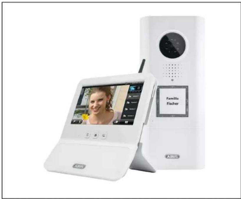
Eycasa Door & House Wireless Video System
natural_image
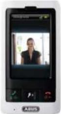
Exterior view of a white Audius smartphone displaying a video call interface and a digital camera module (no readable text or symbols on the device body)User Guide
Version 09/2014
CE
English translation of the original German user guide. Retain for future reference.
Introduction
Dear customer,
Thank you for purchasing this product.
This product complies with current European regulations.
The declaration of conformity can be obtained from:
To maintain this status and to guarantee safe operation, it is your obligation to observe these operating instructions.
Read the entire user guide carefully before starting operation of the product, and pay attention to all operating instructions and safety information.
All company names and product descriptions are trademarks of the corresponding owner. All rights reserved.
In the event of questions, please contact your local maintenance specialist or dealer.

Warning as required by § 201 StGB (German Criminal Code):
Whosoever unlawfully makes an audio recording of the privately spoken words of another, or uses or makes a recording thus produced accessible to a third party, shall be liable to imprisonment or a fine.
Whosoever unlawfully overhears with an eavesdropping device the privately spoken words of another not intended for his attention, or publicly communicates, verbatim or the essential content of, the privately spoken words of another, recorded or overheard, shall incur the same penalty.

Disclaimer
This user guide has been produced with the greatest of care. Should you discover any missing information or inaccuracies, please let us know about them.
ABUS Security-Center GmbH does not accept any liability for technical and typographical errors, and reserves the right to make changes to the product and operating instructions at any time and without prior warning.
ABUS Security-Center GmbH is not liable or responsible for direct or indirect damages resulting from the equipment, performance, and use of this product. No forms of guarantee are accepted for the contents of this document.
Explanation of symbols
 | The triangular high voltage symbol is used to warn of the risk of injury or health hazards (e.g. caused by electric shock). |
 | The triangular warning symbol indicates important notes in this user guide which must be observed. |
 | This symbol indicates special tips and notes on the operation of the unit. |
Important safety information
 | All guarantee claims are invalid in the event of damage caused by non-compliance with this user guide. We cannot be held liable for resulting damage. |
 | In the event of material or personal damage caused by improper operation or non-compliance with the safety information, we cannot be held liable. All guarantee claims are void in such cases. |
This device has been manufactured in accordance with international safety standards.
Please read the following safety instructions carefully.
Safety information
- Power supply
The power supply is 12 V DC from a power supply unit.
Only operate devices using power sources which supply the line voltage specified on the type plate. If you are unsure of the power supply at the installation location, contact your power supply company. Disconnect the device from the power supply before carrying out maintenance or installation work.
- Overloading
Avoid overloading electrical sockets, extension cables, and adapters, as this can result in fires or electric shocks.
- Liquids
Make sure that no liquids of any type are able to enter the device.
- Cleaning
Only use a damp cloth to clean the device. Do not use corrosive cleaning materials.
Disconnect the device from the power supply while doing so.
- Accessories
Only connect devices that are suitable for the intended purpose. Otherwise, hazardous situations or damage to the device can occur.
- Installation position
The Eycasa video door station is designed for use in protected outdoor areas. The Eycasa main unit is only intended for use indoors. The products may be damaged if they are dropped, even from a low height. Install the products so that no direct sunlight can shine on the image sensor. Pay attention to the installation instructions in the corresponding section of this user guide.
Never place the devices close to heaters, stoves, other sources of heat, or in direct sunlight.
Only operate the devices at locations where temperatures within the permitted ambient temperature range prevail.
7. Wireless transmission
The wireless range depends on a variety of environmental factors. The local conditions at the installation site may have a negative impact on the range. A range of up to 100 m can be achieved if there is line of sight between the receiver and transmitter, and a range of up to 30 meters can be achieved indoors (this can be less depending on the situation in the building).
The following environmental conditions compromise both the range and frame rate:
Mobile communication masts, high-tension pylons, electrical wires, ceilings and walls, devices with the same or an adjacent wireless frequency.
Warnings
Observe all safety and operating instructions before putting the device into operation for the first time.
- Observe the following information to avoid damage to the power cable and plug:

- Do not modify or manipulate the power cable or plug.
- Do not pull the cable when disconnecting the device from the power – always take hold of the plug.
- Ensure that the power cable is positioned as far away as possible from any heating equipment, as this could otherwise melt the plastic coating.
-
The power supply unit of the outdoor camera must be protected from damp and moisture.
-
Follow these instructions. Non-compliance with these instructions could lead to an electric shock.

- Never open the housing of the outdoor camera or power supply unit.
- Do not insert any metallic or flammable objects into the device.
-
Use overvoltage protection to prevent damage caused by overvoltage (e.g. electrical storms).
-
Disconnect defective devices from the power immediately and contact your specialist dealer.

If in doubt, have a specialist technician carry out assembly, installation, and connection of the device. Improper or unprofessional work on the power supply or domestic installation puts both you and other persons at risk.
Connect the installations so that the power supply circuit and low-voltage circuit always run separately from each other. They should not be connected at any point or be able to become connected as a result of a malfunction.
Avoid the following adverse conditions during operation:
Moisture or excess humidity (Eycasa main unit)
• Extreme heat or cold
- Direct sunlight (Eycasa video door station)
- Dust or flammable gases, vapors, or solvents
• Strong vibrations
• Strong magnetic fields (e.g. next to machines or loudspeakers)
- The camera must not be directed toward the sun, as otherwise the sensor may be destroyed. (Eycasa video door station)
Unpacking the device
Handle the device with extreme care when unpacking it.

If the original packaging has been damaged, inspect the device. If the device shows signs of damage, return it in the original packaging and inform the delivery service.
Contents
- Intended use....7
- Eycasa system components .... 7
- Features and functions....8
- Device description 9
4.1 Description of the Eycasa main unit....9
4.2 Description of the Eycasa video door station 10
4.3 Description of the Eycasa outdoor camera 14
4.4 Description of the Eycasa Family Care camera 15
4.5 Description of the Eycasa handset.... 16
- Pairing the system components....17
5.1 Pairing the Eycasa components in the Eycasa main unit.... 17
5.2 Pairing the Eycasa video door station.... 17
5.3 Pairing the Eycasa outdoor camera 20
5.4 Assigning the Eycasa Family Care camera 20
5.5 Pairing the Eycasa handset 22
- Mounting the system components 23
6.1 Mounting the Eycasa main unit....23
6.2 Mounting the Eycasa video door station 24
6.3 Mounting the Eycasa outdoor camera 26
6.4 Mounting the Eycasa Family Care camera 27
6.5 Mounting the Eycasa handset.... 28
- System operation 28
7.1 Start-up of the Eycasa main unit.... 28
7.2 Operating the live view.... 29
7.3 Event list and event behavior 31
7.3.1 Playback of event recordings.... 32
7.3.1 Doorbell event.... 33
7.3.2 Proximity key event.... 34
7.3.3 Motion event 35
7.3.5 Family care event.... 36
7.4 General system settings 37
7.4.1 PIN lock settings 37
7.4.2 Software update settings 38
7.4.3 Language settings.... 38
7.4.4 Screen saver settings 39
7.4.5 Audio volume settings....39
7.4.6 Time and date settings.... 40
7.4.7 Network settings 40
7.5 Camera settings.... 42
7.6 Recording settings 44
7.7 Proximity key settings 45
7.8 Settings on the Eycasa handset 47
7.9 Factory settings.... 49
8. Maintenance and cleaning.... 50
8.1 Maintenance .... 50
8.2 Cleaning....50
9. Disposal 50
10. Technical data 51
1. Intended use
The Eycasa wireless intercom system, consisting of a main unit and the video door station, gives you the advantage of using 2.4 GHz wireless digital radio (for video data) and DECT (for audio data) to operate your video intercom. Alternatively, the video door station can be operated on a permanent power supply (recommended) or on batteries at the front door. By connecting the video door station to an electronic door opener, when the doorbell is pressed, the door can be opened from inside using the touchscreen of the main unit – in addition to the video display and voice communication. Alternatively, the optional proximity key allows convenient opening of the door from outside on the video door station.
The Eycasa door & house wireless video system can be expanded with additional components from the Eycasa family: Eycasa outdoor cameras (monitoring of driveways or gardens). The system can manage a total of up to four cameras from the Eycasa product family.
For a detailed description of functions, refer to Section 3, "Features and functions".
2. Eycasa system components
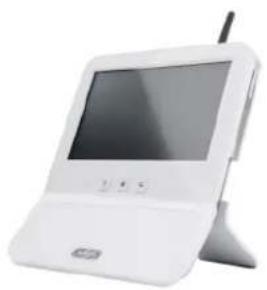
natural_image
White portable electronic device with a screen and antenna, no visible text or symbolsCASA30200 Eycasa main unit
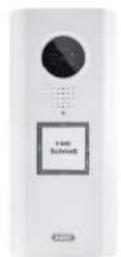
CASA30100
Eycasa video door station

CASA30150
Eycasa battery set
(optional)

CASA30500 (optional)
Eycasa outdoor camera
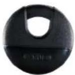
FUBE50020 (optional)
Proximity key
CASA30400 (optional)
Eycasa Family Care
camera
CASA30300
Handset (optional)
3. Features and functions
- Eycasa door & house wireless video system for watching, speaking, listening, and switching
- The Eycasa door & house wireless video system set contains the Eycasa video door station and Eycasa main unit
- Secure wireless transmission using 2.4 GHz digital wireless for video and 1.9 GHz DECT for audio
- Wireless range up to 30 meters (may be less depending on structural conditions) for all Eycasa system components to the main unit indoors
- System expandable to include up to three additional cameras
- Eycasa main unit with 7" touchscreen and built-in microphone and loudspeaker
- Eycasa video door station for use in protected outdoor areas with integrated night vision in close proximity to the camera and control of an electronic door opener
- Eycasa outdoor camera with built-in night vision in close proximity to the camera
- Eycasa Family Care camera with integrated sound detection function (VOX) for indoors
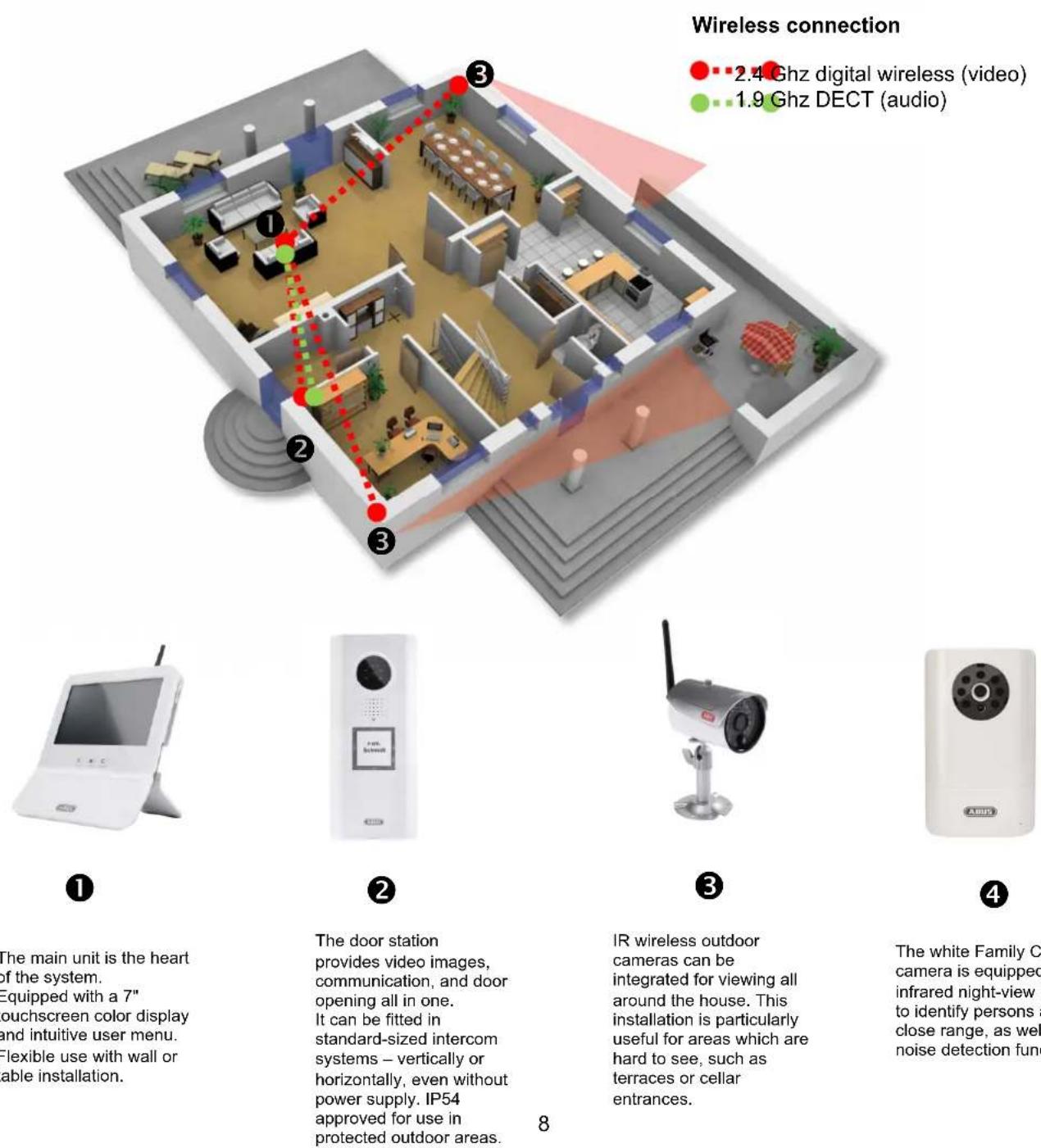
The main unit is the heart of the system.
Equipped with a 7" touchscreen color display and intuitive user menu.
Flexible use with wall or table installation.
The door station provides video images, communication, and door opening all in one. It can be fitted in standard-sized intercom systems – vertically or horizontally, even without power supply. IP54 approved for use in protected outdoor areas.
IR wireless outdoor cameras can be integrated for viewing all around the house. This installation is particularly useful for areas which are hard to see, such as terraces or cellar entrances.
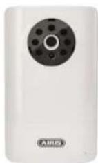
The white Family Care camera is equipped with infrared night-view LEDs to identify persons at close range, as well as a noise detection function.
4. Device description
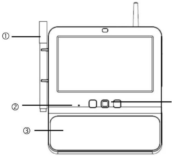
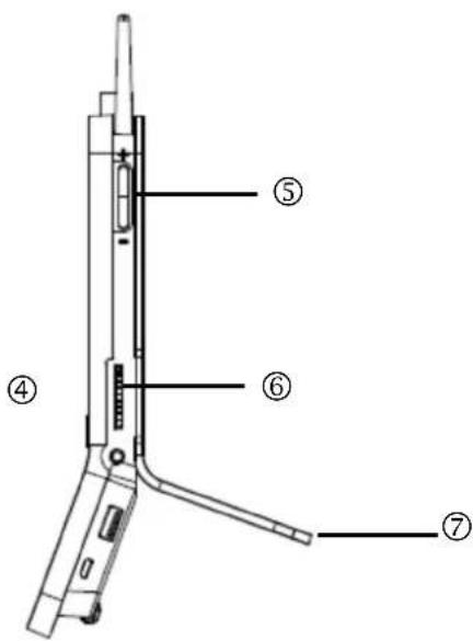
4.1 Description of the Eycasa main unit
natural_image
Technical line drawing of a mechanical component with internal channels and mounting holes (no text or symbols)⑧ ⑨
| 1 | Board marker | Used for writing short notes on the memo board. Dry erase board marker. |
| 2 | Microphone | Intercom for Eycasa video door station and Eycasa FamilyCare camera. |
| 3 | Memo board Glass plate for short notes with Eycasa board marker. | |
| 4 | Eycasa control buttons | [SW63] Switch to event list. |
 Switch to live image. Switch to live image. | ||
| [TT42T] Back button (within menus). | ||
| 5 | Volume control | +: Increases the volume during voice communication.▪: Reduces the volume during voice communication. |
| 6 | SD card | Slot for SD card for software updates and recording.Supports SD cards up to 32 GB SDHC. |
| 7 | Table mount | Removable table mount, can be used instead of the included wall mount. |
| 8 | Power supply | 12 V DC / 1 ADevice starts automatically when powered by line voltage. |
| 9 | RJ45 connection Integrated network access, 10/100 Mbps. | |
| 10 | Loudspeaker System loudspeaker for outputting audio. | |
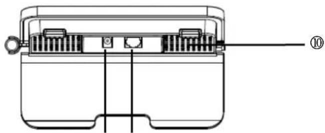
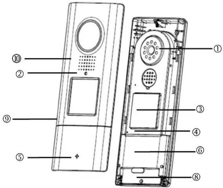
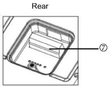
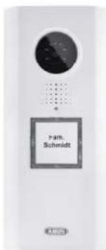
4.2 Description of the Eycasa video door station
| 12V-24VAC/DC | RELAY1 | RELAY2 |
| 1 | Camera Camera module with fixed lens including photo sensor | |||
| 2 | Status LED | Indicates the current device status | ||
| LED red Permanently lit | The sequence for doorbell ringing is being carried out. | |||
| LED green Permanently lit | Voice connection has been established. | |||
| LED red Flashing | No wireless connection to the main unit or device is not paired. | |||
| LED red + green | Flashing fast Pairing mode active. | |||
| LED off Permanent | Indicates that the device is ready to operate when voltage is present. | |||
| 3 | Doorbell button | Backlit doorbell button (not in battery mode).Backlighting switches on automatically in night mode (camera photo sensor).When the doorbell button is pressed, a connection to the Eycasa main unit is established with a video image. | ||
| 4 | Microphone | Built-in microphone for two-way voice communication with Eycasa main unit or handset. | ||
| 5 | ABUS logo | Logo can be rotated 90° with horizontal installation of the video door station. | ||
| 6 | Proximity reader | Built-in proximity reader for use of the ABUS wireless chip key (FUBE50020) for opening the door on the door station.Not available in battery mode. | ||
| 7 | Connector block (Rear) | Connector block for power and relay contacts (potential-free, NO)Voltage: 12–24 V AC/DCRelay 1 = door openerRelay 2 = electronic chimeNot available in battery mode. | ||
| 8 | Battery compartment | Removable battery compartment for 6 x AA batteries (1.5 V).Use CASA30150 for this. | ||
| 9 | Microphone Two-way communication for Eycasa main unit. | |||
| 10 | Loudspeaker | Integrated loudspeaker. | ||
 | Important:The video door station is subject to limitations in battery mode to ensure the longest possible battery life. The following functions are disabled:proximity key, backlighting of the doorbell button, door opener function (no relay triggering), continuous video transmission.In battery mode, the door station operates in a power-saving mode and wakes up when the doorbell is pressed. In this case, it takes approx. 5 seconds to establish a connection to the main unit.We recommend that you run the video door station on a permanent power supply to be able to use the full functionality. |
Connection examples for an electronic door opener/door bell
Description of the terminal block
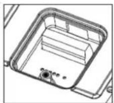
natural_image
Technical line drawing of a mechanical housing or enclosure component (no text or symbols)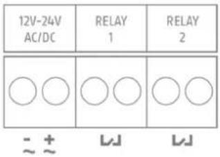
| Description Note | |
| 12V-24AC/DC | Network connection for video door station 12-24V direct current or 12-24V alternating current |
| RELAY1 | Terminal connector for electronic door opener.Potential-free relay, NO (normally open) |
| RELAY2 | Terminal connector for electronic door bell.Potential-free relay, NO (normally open) |
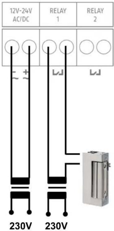
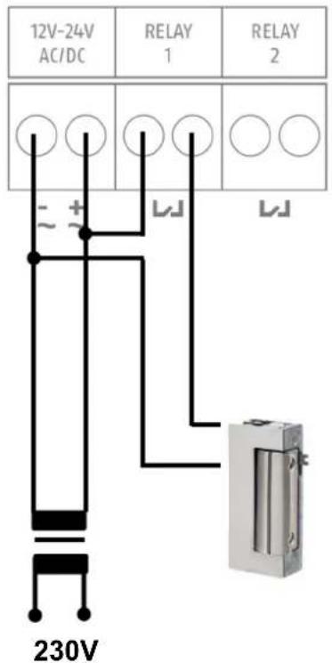
Connection for an electronic door opener:
Connect the electronic door opener to RELAY 1, using either a separate power supply unit (version A) or directly (version B) via the power supply of the video door station.

For version B, take note of the permitted power supply for your door opener:
• A voltage that is too high can damage your door opener.
- If the power consumption is too high for the switching procedure, the network supply for your video door station can fail. Ensure that the power supply unit for your video door station has a sufficient rating (min. 1A or higher).
Version A
Version B
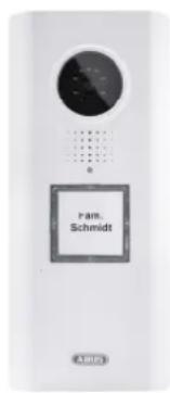
Connection for an electronic door bell:
Connect the electronic door bell to RELAY 2. Before use, ensure that your door bell has a suitable opening contact for triggering. The door bell is supplied with power via the door bell's intended voltage source (separate power supply unit or batteries).

When using an electromechanical door bell, use the power supply via RELAY 2 so that the bell is triggered when switched by closing the circuit.

The function to trigger the door bell via RELAY 2 requires the software version Eycasa 1.5 or higher. You can download the software free of charge from the following website: http://www.abus.com/ger/Sicherheit-Zuhause/Tuersicherheit/Tuersprechsysteme/Eycasa/Eycasa-Tuer-Haus-Funk-Videosystem
Electronic
door bell
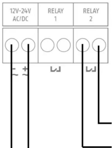
Electromechanical door bell
4.3 Description of the Eycasa outdoor camera
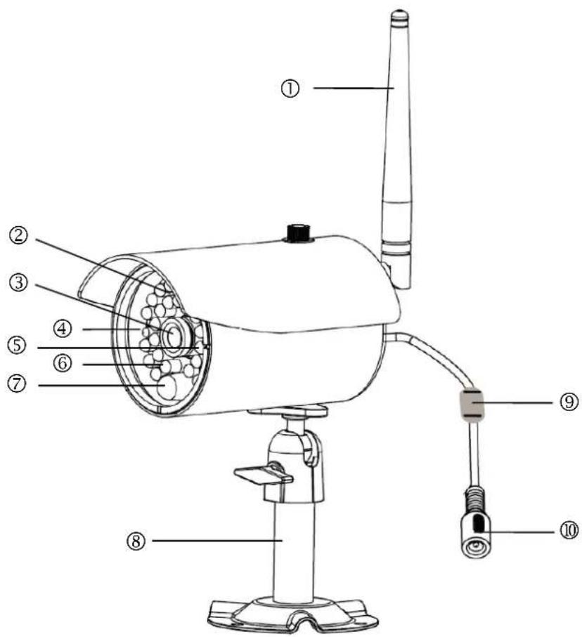
| 1 | Antenna Screw-on antenna for 2 | 4 GHz digital wireless. | ||
| 2 | Photo sensor Sensor for switching | between day and night mode. | ||
| 3 | Camera Camera with fixed lens. | |||
| 4 | Power LED | LED red Permanently lit Power supply connected. | ||
| LED off Permanent No power supply connected. | ||||
| 5 | Link LED | LED green Lit | Camera is providing an image signal to the main unit. | |
| LED green Flashing Pairing mode active. | ||||
| LED off Permanent | Camera not paired or not accessible through the main unit. | |||
| 6 | IR LEDs Built-in IR LEDs. Activated in night mode. | |||
| 7 | PIR sensor | The PIR sensor reports motion detection to the Eycasa main unit. | ||
| 8 | Camera mount Wall mount for camera mounting. | |||
| 9 | Pairing button | Pairing button for programming the wireless camera in the Eycasa main unit. | ||
| 10 | Power supply Connection for 5 V | DC / 1 A power supply | ||
4.4 Description of the Eycasa Family Care camera
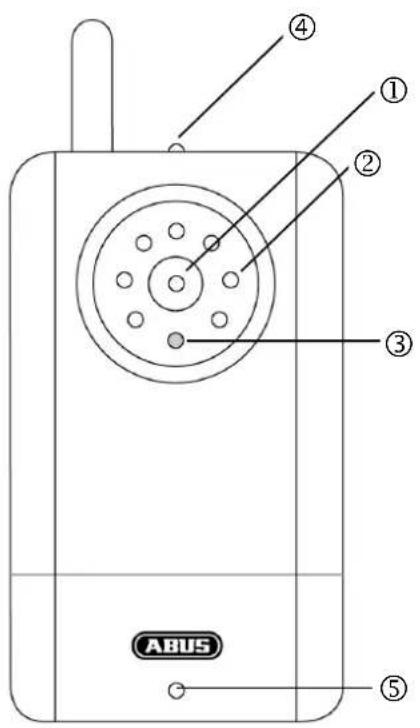
| 1 | Camera | Camera module with fixed lens and IR LEDs, including photo sensor. | ||
| 2 | IR-LEDs Built-in IR LEDs. Activated in night mode. | |||
| 3 | Light sensor Sensor for switching between day and night mode. | |||
| 4 | Status LED | Indicates the status of Family Care camera | ||
| LED red+green | Flashing | Camera pairing in progress | ||
| LED green Permanent | Connection to main unit OK | |||
| LED green Flashing | Audio connection to main unit established | |||
| LED red Flashing slowly | Connection to main unit interrupted | |||
| LED red | Flashing quickly | Battery critically low | ||
| 5 | Mikrofone | Built-in microphone for two-way communication with Eycasa main unit and voice detection using VOX function. | ||
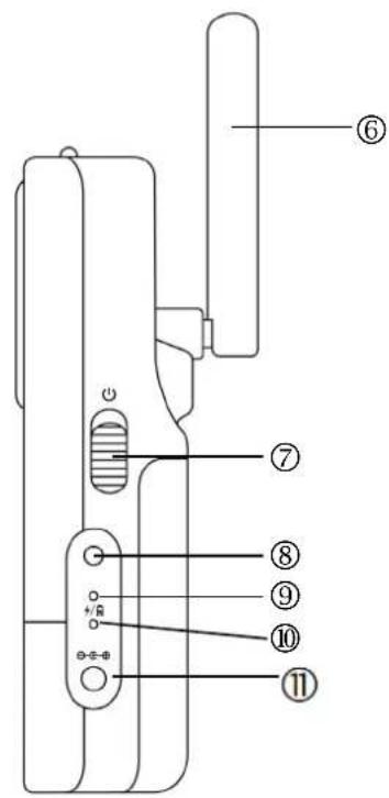
| 6 | Antenna Antenna for 2.4 GHz digital wireless. | |||
| 7 | Power button | Switch on Family Care camera (press for 3 seconds).Switch off Family Care camera (press for 3 seconds). | ||
| 8 | Pairing button | Pairing button for assigning the Family Care camera in the Eycasa main unit. | ||
| 9 | Reboot button Reboots the Family Care camera. | |||
| 10 | Power LED | Indicates the operation status of Family Care camera. | ||
| LED off Power off | ||||
| LED on Camera ready for operation | ||||
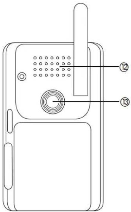
| 13 | Power supply 5 V DC / 1 A | |||
| 12 | Loudspeaker | Integrated loudspeaker. | ||
| 13 | Thread for bracket Camera mount for versatile attachment. | |||
4.5 Description of the Eycasa handset
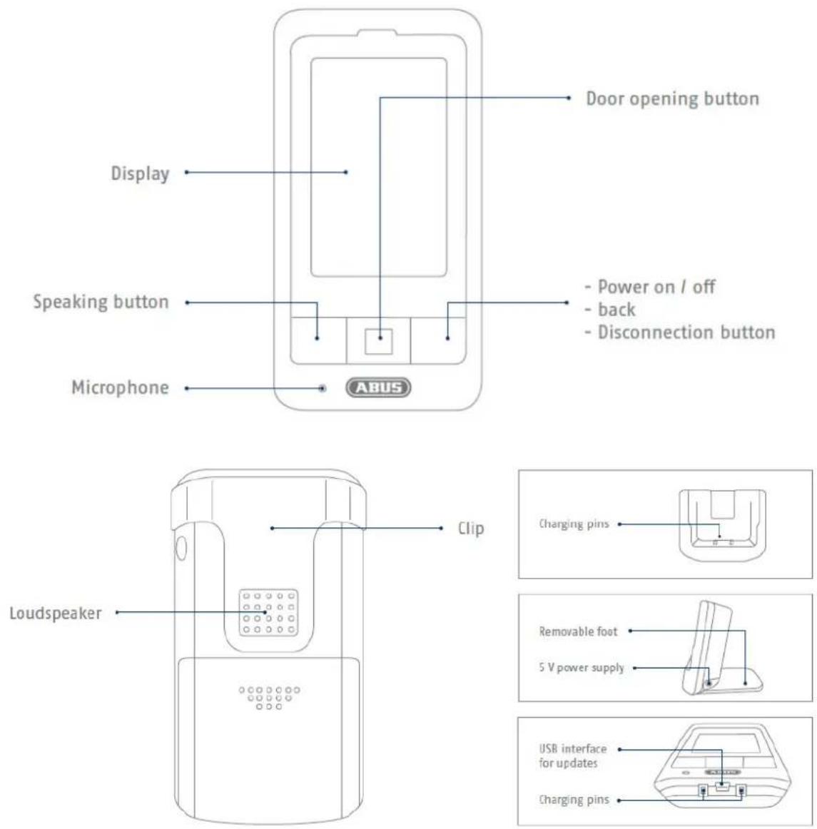
The handset is equipped with a touch-sensitive display. For the settings, please jump to menu item 7.8.
 | To switch the handset on or off, please press and hold the red button for at least 5 seconds. |
 | When the handset battery is discharged, a signal tone will be emitted in regular intervals.Please place the handset in the charging cradle. The handset will be fully charged after approx. 5 - 6 hours. |
5. Pairing the system components
5.1 Pairing the Eycasa components in the Eycasa main unit
We recommend that you pair the video door station in the entrance area to camera position 1 (factory setting with the CASA31000). All other components can be paired to any of the other camera positions. Pair the components as follows:

Note:
The CASA31000 Eycasa video door station and Eycasa main unit included in delivery are already programmed at the factory.

Important:
Before you begin installing, make sure that the wireless transmission range is adequate at the site of the required installation.
Start pairing the system components before you perform the final installation of the individual Eycasa components.
-
Connect your Eycasa main unit and the components to be paired to the associated power supply unit / power supply.
-
Wait until your Eycasa main unit has completed the boot process, and switch to the configuration menu
by pressing the

-
Click the "Cameras" menu item and select a free camera channel.
-
Press the "Pair camera" button to start the pairing process using the setup wizard.
-
In the setup wizard, select your camera model as shown in the figure.
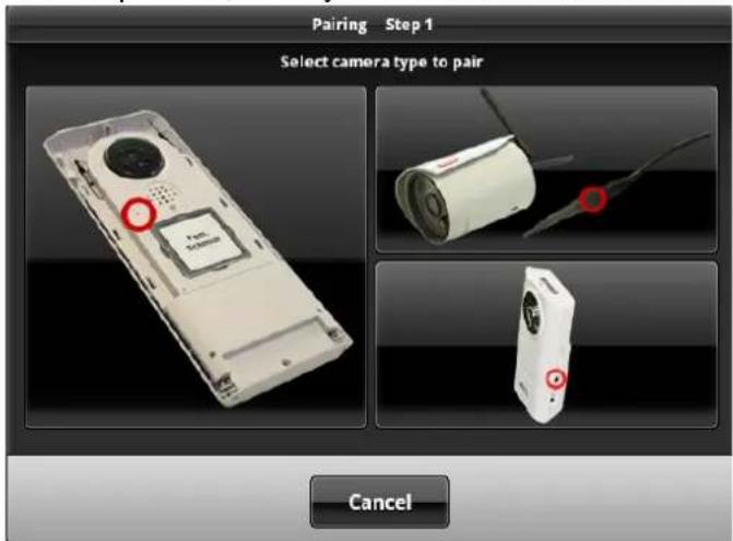
The setup steps are described below separately for each camera type.
5.2 Pairing the Eycasa video door station
Connect your video door stations with the power before starting the pairing process. Your video door station indicates the current status by the flash code on the status LED. If the video door station is not paired in your Eycasa main unit, the status LED flashes red.
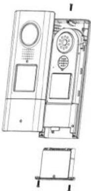
The video door station housing must now be opened for the pairing process. Use the included screwdriver to loosen the safety screws above the lens and below the battery compartment.

natural_image
Technical line drawing of a rectangular electronic device with internal components (no text or symbols)First remove the battery compartment to be able to remove the front cover.
natural_image
Technical line drawing of a device casing with internal components and a separate exploded view (no text or symbols)You can now continue the pairing process for your video door station. The setup wizard of your main unit should show the following view:
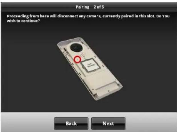
A notification message will appear that a camera already paired to the selected camera slot will be overwritten by this action. Press Next if you are sure you want to continue with the pairing process.
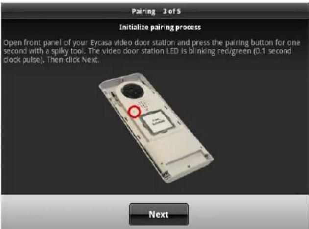
If your video door station is running on batteries, then you need to press the doorbell button once to wake up the device from standby mode. Now press the pairing button on your video door station. The status LED on your video door station flashes alternately red and green to indicate that the pairing process has started. The pairing process is active for 120 seconds. Press the "Next" button.
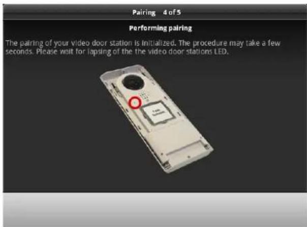
Your Eycasa main unit connects to your video door station. The process can take several seconds. The setup wizard will signal whether the process is complete or whether it needs to be repeated due to a pairing error.
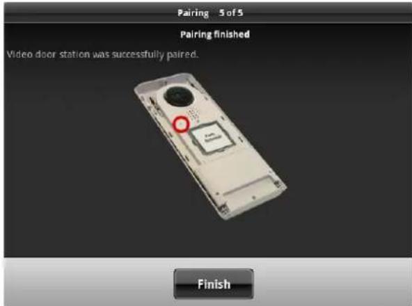
If the message "Video door station was successfully paired" appears, the pairing process is finished. The status LED goes out on your video door station, signaling readiness.
You can proceed with installation of the unit from Chapter 6.
| Note:If you want to test the video door station after initial start-up, note that there can be audio feedback loops both in the loudspeaker of the door station and the main unit if the devices are too close to each other. This is normal and occurs only when both devices are installed in the same room. |
5.3 Pairing the Eycasa outdoor camera
Ensure that your Eycasa outdoor camera is supplied with power.
You can now proceed with the pairing process for your outdoor camera. The setup wizard of your main unit should show the following screen:
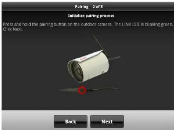
Follow the instructions on the screen and press and hold the pairing button on the power cable of the camera. The link LED of the camera starts to flash. Now press "Next" without releasing the pairing button.
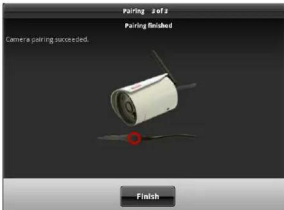
Once the message "Camera pairing succeeded" appears, you can release the pairing button. The pairing process is completed. If an error occurs during the process, repeat the previous pairing steps.
5.4 Assigning the Eycasa Family Care camera
Make sure that your Eycasa Family Care camera is supplied with power.
You can now proceed with the assignment process for your Family Care camera. The setup wizard of your main unit should show the following screen:
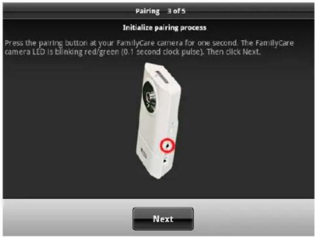
Follow the instructions on the screen and press and hold the pairing button on the camera. The Status LED on the camera starts flashing red and green. Now press "Next".
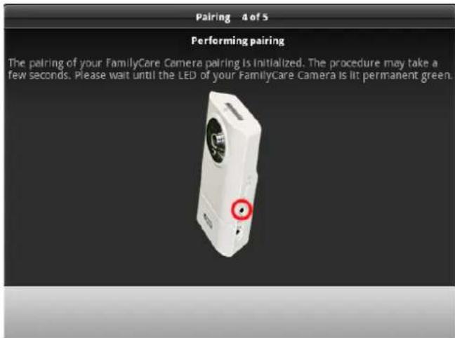
Your Eycasa main unit then connects to the Family Care camera. The process can take several seconds. The setup wizard will signal whether the process is complete or whether it needs to be repeated due to a pairing error.
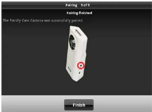
If the message "Family Care camera was successfully assigned" appears, the assignment process is finished. If an error occurs during the process, repeat the previous assignment steps.
You can now proceed with the installation of the unit (see section 6).
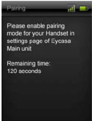
5.5 Pairing the Eycasa handset
Open the settings in the Eycasa main unit and jump to the "Handset" menu item.
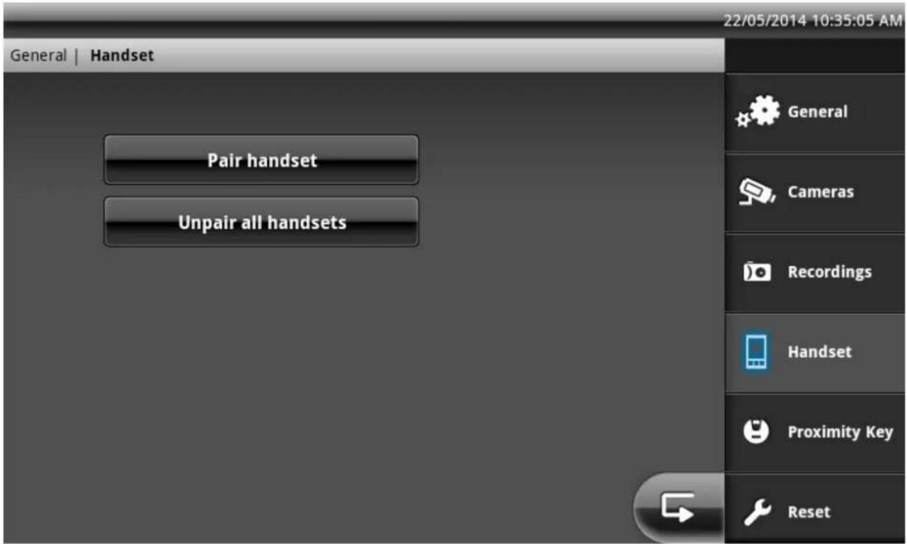
Select "Pair handset". The main unit will now wait for a handset which is also in pairing mode.
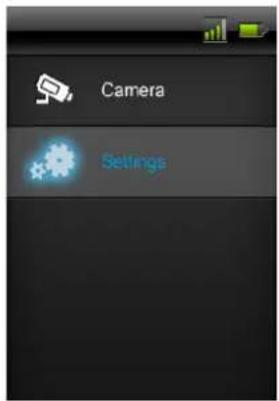
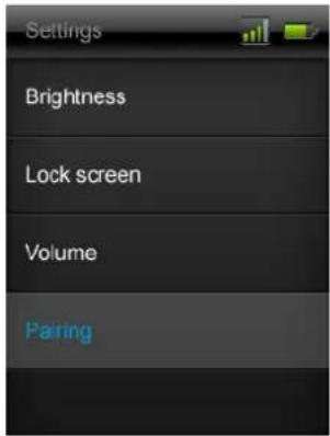
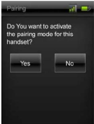
In your handset, select "Yes" under "Settings" / "Pair" to start the learning process. The learning process takes approx. 30 seconds and is acknowledged by a message, "Pairing". If the pairing process fails, please ensure that the handset is located in the immediate vicinity of the main unit during the pairing process.
Step 1
Step 2
Step 3
Step 4
6. Mounting the system components
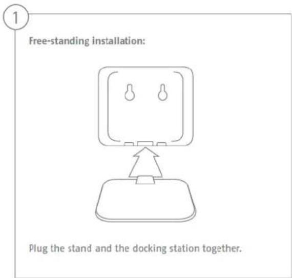
6.1 Mounting the Eycasa main unit
The Eycasa main unit can be installed either on a table or wall. When delivered, the table mount is already attached, allowing you to place the device wherever you would like indoors. Alternatively, the back cover of the main unit can be replaced with the included wall mount. The following steps describe how to install the wall mount.
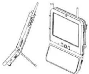
natural_image
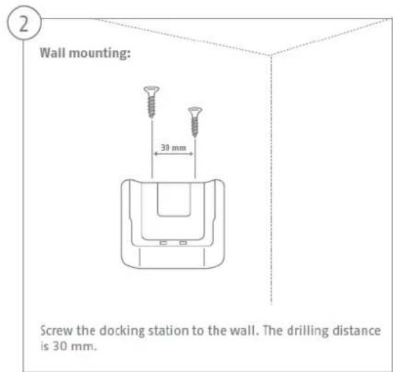
Technical line drawing of a laptop device showing front and side views (no text or symbols)| Important:Choose the installation location of the main unit so that optimal range of all Eycasa components is possible. Make sure that a distance of no more than 30 m (depending on the building characteristics, this can be less) from the main unit is not exceeded. Additional walls can reduce the wireless range. Test the range before installation. |
- Remove the table mount on the rear of the device by pushing the back cover downwards and off. Be sure not to touch or damage electronic components while the main unit is open.
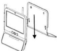
natural_image
Diagram of a laptop computer with an open screen and a separate flatboard, showing no text or symbols.- Put the wall mount into the desired position on the wall and mark the drill holes. The distance between the two holes is 102 mm.
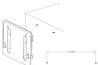
natural_image
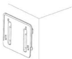
Pure technical line drawing of a mechanical component with no text, numbers, or symbols- Attach the screws using wall plugs and put on the wall mount. The wall mount should be completely screwed together only after placement onto the screw heads.
natural_image
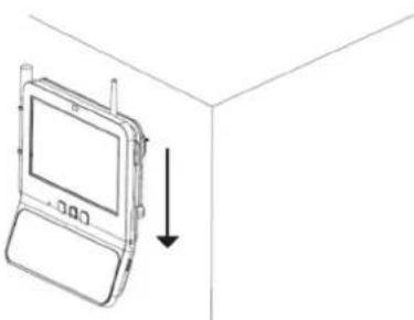
Simple line drawing of a 3D rectangular frame with two vertical connectors, no text or symbols present.- Now place the main unit on the wall mount and connect the included power supply unit.
natural_image
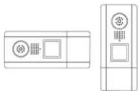
Line drawing of a mobile phone with a screen and antenna, shown in 3D perspective (no text or symbols)6.2 Mounting the Eycasa video door station
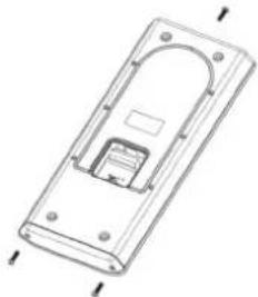
The Eycasa video door station can be mounted either horizontally or vertically. The video door station is designed for use in protected outdoor areas, thanks to its degree of protection of IP54.
natural_image
Two technical line drawings of electronic components: a front panel with circular and square indicators and a side-view view with square and grid symbols (no text or labels)
Note:
In case of horizontal installation, in the settings you need to change the orientation of the video image to 90^ to the left or right.
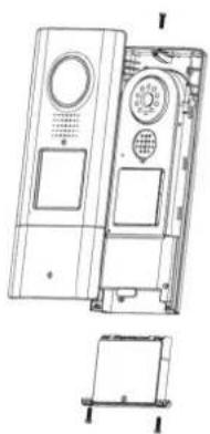
Use the included screwdriver to loosen the safety screws above the lens and below the battery compartment.
natural_image
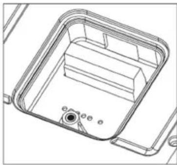
Technical line drawing of a rectangular electronic device with internal components and mounting holes (no text or symbols)If you are operating your video door station with a permanent power supply (bell transformer), remove the cover of the terminal connector on the rear of the device.
Be sure to reinstall the sealing ring later.
First remove the battery compartment to be able to remove the front cover.
natural_image
Technical line drawing of a device casing with internal components and a separate exploded view (no text or symbols)You can now open the plastic cover of the doorbell button and attach your nameplate. For labeling, you can use the included nameplate or the PDF template on the included CD.
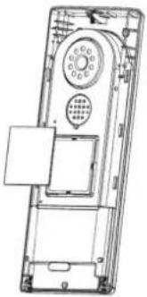
natural_image
Technical line drawing of a mobile phone casing with keypad and door (no text or symbols)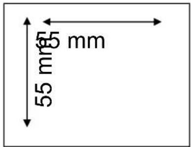
Connect the power (12–24 V AC/DC) and an optional electronic door opener (RELAY 1) and/or an electronic door bell (RELAY2) to the terminal block of the video door station.
natural_image
Technical line drawing of a mechanical housing or enclosure component (no text or symbols)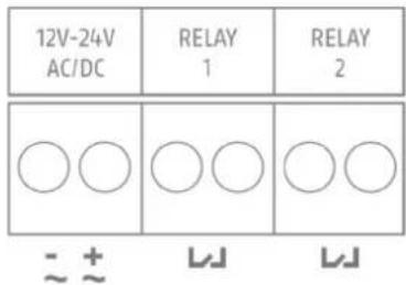

Note:
In software version 1.0, RELAY 2 is disabled for the Eycasa main unit.

Important:
When operating with a permanent power supply (e.g.: bell transformer), the video door station requires up to 800 mA at 12 V. Make sure that downstream consumers (such as electronic door openers) do not exceed the total output of the voltage source.
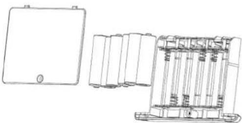
If you operate the video door station alternatively using batteries, insert the batteries into the battery compartment. Pay attention to the polarity when inserting the AA batteries.
natural_image
Technical line drawing of a device housing and internal components (no text or symbols)
Important:
The video door station is subject to limitations in battery mode to ensure the longest possible battery life. The following functions are disabled:
Proximity key, backlighting of the doorbell button, door opener and door bell function (no relay triggering), continuous video transmission.
We recommend that you run the video door station on a permanent power supply to be able to use the full functionality.
After connecting the power supply, mount the video door station on the house wall.
The recommended installation height is 1.6 meters between the ground and camera module. Put on the video door station at the desired location and use the screw holes on the bottom shell to mark the drill holes.
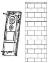
After finishing the wall mounting, put the door station back together to complete the installation.
6.3 Mounting the Eycasa outdoor camera
Use the camera mount to help you find a suitable place for installation. Use the drill holes to mark the surface, and drill the holes. Insert the included wall plugs before you attach the mount with the screws.
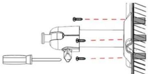
natural_image
Technical diagram of a mechanical assembly with screw fasteners and a tool, no text or symbols presentYou can also swivel the mount by 90^ into a particular position. First loosen the screw on the side and set the required angle. Then tighten the screw to secure the required position.
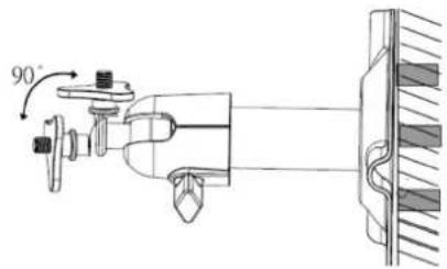
Screw the camera onto the mount and connect the power supply unit to the camera.
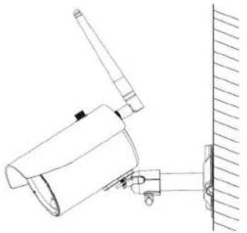
natural_image
Technical line drawing of a mechanical device mounted on a wall, showing no text or symbols.
Important:
Only use the included antenna for installation.
6.4 Mounting the Eycasa Family Care camera
Bolt the camera onto the bracket and select a suitable place to mount it.
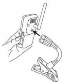
natural_image
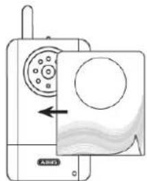
Illustration of hands using a handheld device to clamp or adjust a clip (no text or symbols visible)You can decorate the camera with one of the stickers provided.
natural_image
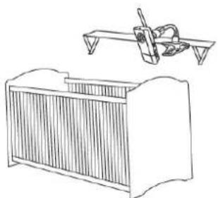
Diagram of a device with a circular component and directional arrow, no readable text or symbols present.The camera should be mounted no further than 3 metres away from the child in order to ensure optimum visibility and reliable sound detection.
natural_image
Line drawing of a vintage office chair with a flatboard and a hand tool above it (no text or symbols)
Important:
Please make sure the camera and the cable are well out of reach of your child in order to prevent the risk of strangulation.
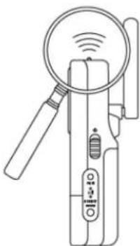
Please note that if you only operate the camera with the battery, it must be charged as soon as possible after the power LED starts flashing.
natural_image
Line drawing of a handheld device with a magnifying glass and control buttons (no text or symbols)
Important:
Note that the camera contains a built-in battery, which must be fully charged before the first use. The status LED lights up green as soon as the battery is fully charged.
6.5 Mounting the Eycasa handset
7. System operation
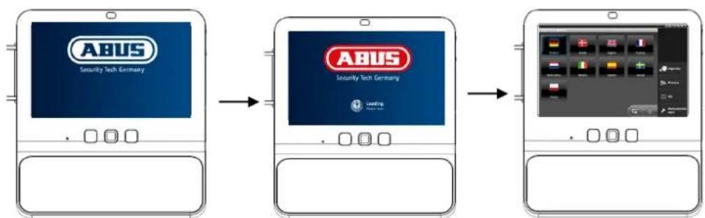
7.1 Start-up of the Eycasa main unit
flowchart
graph LR
    A["Product Selection"] --> B["Application Setup"]
    B --> C["Final Application"]
Sequence:
- Connect the power supply unit to your Eycasa main unit.
- The device starts automatically after the line voltage is present.
- Wait until the boot process is complete.
- During initial start-up, the system language is set after the system boots.
- Select the language by pressing the corresponding country flag on the display.
- Press the button twice to return to the live view.
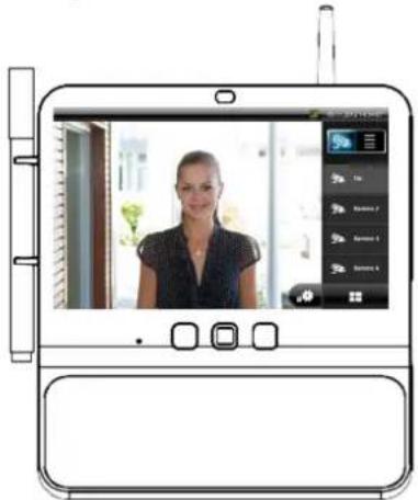
7.2 Operating the live view
natural_image
Illustration of a person in front of a tablet device with a screen showing a photo, no visible text or symbols on the device itself.Individual image view
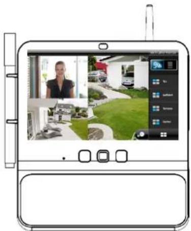
4x view
The Eycasa main unit has a touchscreen interface; all functions are operated by finger pressure on the appropriate button. In the live view, the following adjustment options and displays are available:
 | Switching between live view and event list. | |
 | Display of the signal strength of the currently selected cameras. Note that the signal strength may be displayed only when there is active image content. In the 4x view, this function is not available. | |
 | Manually select camera 1 to 4 for the individual image view. | |
 | Switches between individual image view and 4x view. | |
 | Button opens the system settings of the Eycasa main unit. |
 | Key | Operates RELAY 1 on the video door station to open the door. | |
 | Receiver | Establish/terminate a voice connection to the video door station. | |
 | Lullaby | Play a preset lullaby on the Family Care camera for 90 seconds.The lullaby is repeated until 90 seconds have passed. You can endthe lullaby manually by pressing the button. | |
 | Monitoringmode | Activates monitoring mode on the Family Care camera (voiceactivation is enabled). The function remains active until it is manuallydeactivated again. | |
 | |||
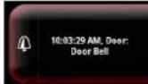 | Information window regarding pending/missed event with details on cameraname, time stamp, and event type. An event must be acknowledged before otheroperator inputs on the touchscreen are possible. Events are acknowledged byfinger pressure on the corresponding message.A counter below the event message indicates how many events have occurredsince the last acknowledgment. | ||

Note:
In the factory setting, the Eycasa main unit switches to the screen saver after 2 minutes of inactivity (no touchscreen inputs or event messages). You can change this in the screen saver menu item.
7.3 Event list and event behavior
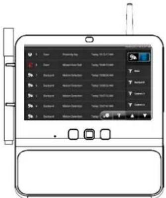
Event list
In the event list, the following control options are available:
 | Changes the view to the event list.You can browse through the event list in steps of seven using thebuttons. The event log includes 500 entries. | |
 | Opens the general filter dialog of the event list. After activation of the filter type,only events of the selected type are displayed. | |
 | When a camera is selected, the event list only shows events of the selectedcamera. The camera filter can be combined with the general event filter. | |
 | Deleting the event log: If you press the “Delete event log” button, the entire eventlog in the Eycasa main unit is deleted and all the associated video recordings aredeleted from the SD card. | |
 | Video recording: There is a recording of the selected event. Tap the eventmessage to play the recording. | |
 | Video recording missing: There is a recording of the selected event, but it was notfound on the SD card (the SD card was removed or the recording was manuallydeleted). | |
| [KKT4] | Doorbell event: Shows the time of the doorbell ringing of an Eycasa video doorstation. | |
| [4526] | Proximity key: Shows the time the door was opened by a wireless proximity keyon the video door station. | |
 | Doorbell rings missed: Shows the time of a missed doorbell ring. This event isalways displayed when the previous doorbell ring was not acknowledged within30 seconds. | |
 | Motion: Shows the time of motion detection by the PIR sensor of an Eycasaoutdoor camera. | |
 | Family Care: Shows the time of a VOX alarm on the Family Care camera. | |
 | Family Care missed: Shows the time of a missed VOX alarm. This event isalways displayed when the previous VOX alarm was not acknowledged within 30seconds. | |
| [KXOK] | Video signal failure: Shows the time of a failed signal connection between themain unit and camera. This message appears when the wireless signal fails forlonger than 1 minute. | |
Battery strength: Shows the time of weak battery strength on an Eycasa video door station and Family Care camera. When the battery is low, the video door station automatically switches off video transmission. Change the batteries promptly if this message appears.
7.3.1 Playback of event recordings
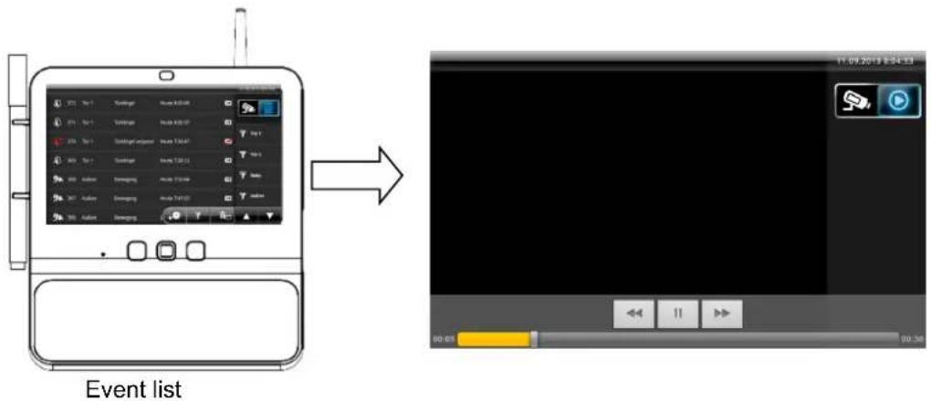
| Possible user actions Effect | |
| Select an entry with the video symbol from the event list | The view automatically switches to playback and the video is played. The control buttons are automatically hidden after a short while. Touch the monitor once to see the control buttons again. The view automatically switches back to the event list once the video has been completely played back. |
| Press the buttons | Fast forward/rewind playback. |
| Press the button | Pause replay |
| Drag the time line | Position the playback button horizontally by dragging and dropping it anywhere on the time line to skip to a particular point during playback. |

Note:
Alternatively, you can press the "Back" and "Event list" buttons on the main unit (below the screen) to end playback of a video file.
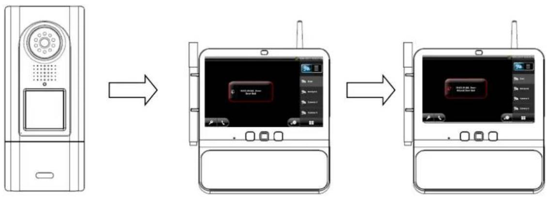
7.3.1 Doorbell event
flowchart
graph LR
    A["Front Panel"] --> B["Screen with Display"]
    B --> C["Back Panel"]
Sequence of doorbell ringing:
- Doorbell is pressed on the video door station.
- The screen on the Eycasa main unit is activated.
- RELAY2 on the door station is switched for 2 seconds to activate the door bell.
- The live image of the video door station is displayed.
- Video recording is started on the video door station and continues for up to 30 seconds (if the "Activate video recording" option was selected in the settings).
- The doorbell tone plays.
- The event message is displayed on the screen.
- At the same time, the video image and a doorbell signal are sent to the CASA30300 handset (optional).
| Possible user actions on the handset | Effect | |
| Acknowledge the event message The | doorbell ringing is interrupted. | |
| After the event message is acknowledged, the and buttons can be pressed. | ||
Press the button  | The event message is acknowledged and the doorbell ringing ends.An active voice connection for the video door station is established and maintained for up to 60 seconds. | |
Press the button  | The event message is acknowledged and the doorbell ringing ends.Press the door opener (RELAY 1) on the video door station. | |
| No response Doorbell ringing stops after 30 seconds. | ||
| Video connection is disconnected after 30 seconds unless “Camera permanently active” has been selected.The “Missed Door Bell” event message is saved on the main unit. | ||
| Possible user actions on the handset | Effect | |
 | Sets up a voice connection to the door station | |
| Triggers the door opener. No active voice connection is set up. The call is then disconnected automatically. If the button is pressed during an active voice connection, this will also result in the call being disconnected. | ||
 | Hang up/reject. An active voice connection can be disconnected by pressing the red button. If an incoming call is not answered, this button disconnects the call directly without any interaction. | |
7.3.2 Proximity key event
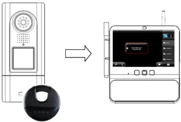
Sequence of the proximity application:
- Hold the paired proximity key up to the video door station.
- The door opener (RELAY 1) on the video door station is operated.
- The screen on the Eycasa main unit is activated.
- The live view switches to the video door station with the activated proximity key.
- The event message is displayed on the screen.
7.3.3 Motion event
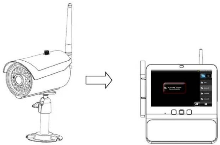
Sequence of motion detection:
- Outdoor camera detects motion using the integrated PIR sensor.
- The screen on the Eycasa main unit is activated.
- The view switches from 4x view to the individual image view of the outdoor camera.
- The event message is displayed on the screen.

Important:
Event messages from external cameras are only detected in the 4x view (activated by default) or with the currently selected camera. If the main unit is in the individual image view, only the currently displayed outdoor camera can detect motion.
7.3.5 Family care event
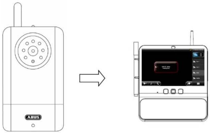
Voice activation sequence:
- The VOX function of the Family Care camera is activated using the monitoring function on the main unit.
- The integrated voice detection function of the Family Care camera detects a sound source.
- The screen on the Eycasa main unit is activated.
- The live image of the Family Care camera is displayed.
- An audio connection to the Family Care camera is started up (listening only) for 30 seconds.
- The event message is displayed on the screen.
| Possible user actions Effect | |
| Acknowledge the event message The | event message is hidden. |
You can also press the  and and  and ns after the event message has been acknowledged. and ns after the event message has been acknowledged. | |
Press the button  | The event message is acknowledged.An active voice connection to the Family Care camera is established and maintained for up to 60 seconds. |
Press the button  | The event message is acknowledged.A lullaby is played on the Family Care camera for 90 seconds. |
| No response An audio connection (listening only) to the Family Carecamera is maintained for 30 seconds.The video connection is ended after 30 seconds if the camera is in battery mode.The event message “Family Care missed” is saved. | |
7.4 General system settings

Pressing the button gives you access to the system settings. Note that you can block access to the settings menu by assigning a PIN.
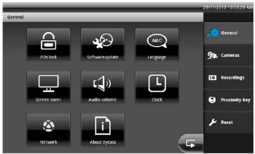
You can save settings in the submenus by pressing the the higher-level item in the main menu.

button. Pressing this button also takes you to
7.4.1 PIN lock settings
By assigning a 4-digit PIN, you can secure your Eycasa main unit against unauthorized access to the system settings. After the function is activated, your PIN is requested every time the system settings are called up.
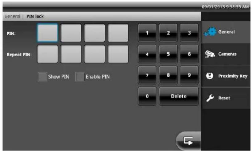
PIN Entry of a 4-digit number on the on-screen keypad.
Repeat PIN Confirmation of the entered PIN to avoid typos.
Show PIN Display the PIN code during entry.
Enable PIN Activates the PIN lock function.

Information:
The PIN lock setting is retained even after the device is turned off or restarted. If you lose your PIN, a restore is possible using the SuperPIN. To use the SuperPIN, enter the time displayed on the device in the format HHMM (H = hour / M = minute) as the PIN.
7.4.2 Software update settings
Here you can update the software of your Eycasa main unit using an SD card.
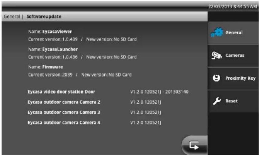
On our homepage, http://www.abus.com, you can check whether a new firmware file is available for the CASA31000 Eycasa main unit. The following steps must be carried out with the update:
- Download the firmware update from the ABUS homepage.
- Unzip the update to an SD card.
- Insert the SD card into main unit and start updating.
You can find the remaining steps in the readme file included with the download. Before the update, make sure your SD card is formatted as FAT32.
7.4.3 Language settings
Select the desired system language for your Eycasa main unit.
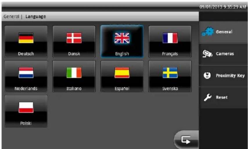
Upon reset or during initial start-up of the main unit, a system language must first be selected.
7.4.4 Screen saver settings
Select the activation time for the screen saver.
![General | Screen saver Shade display after [minutes] 2 5 10 30 60 General Cameras Recordings Proximity Key Reset 02/10/2013 2:25:41 PM](/content/2026/06/1168027/images/a01af18fb9248a2ccf312143e1f79964371c575676fbbe0126d9505232e15e6d.jpg)
The screen saver is automatically activated after the set time if during this time there has been no user input on the touchscreen and no events on the main unit. The monitor dims in this mode, but the system functions are still active.
The screen saver is automatically deactivated at any time if the touchscreen is touched anywhere or if an event occurs.
| Important:If the screensaver mode is started, the Eycasa main unit will close the connection to all connected Eycasa Outdoor cameras automatically after 90 minutes.Alarm messages and camera loss events will not be detected in this state. After the screensaver is stopped the Eycasa outdoor cameras are available again with full functionality. |
7.4.5 Audio volume settings
Here you set the volume of the currently selected doorbell ring tone and the touch-click volume within the software.
![General | Audio volume Volume ring tone [%] 0 25 50 75 100 Volume touch click [%] 0 25 50 75 100 General Cameras Proximity Key Reset](/content/2026/06/1168027/images/af65adc427e5bb46a5359ab40b37759159a9c8e6fb82254cb4bbbe1d6abf4bc6.jpg)
7.4.6 Time and date settings
Here you set the current time, date, and time zone. These settings are important for proper recording of the messages in the event log of the main unit.
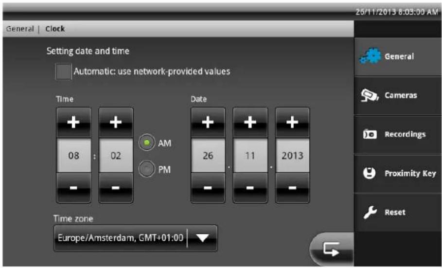
Activate the “Automatic” setting if your Eycasa main unit is connected to your home network (which provides access to the internet). The current time is identified automatically via NTP (Network Time Protocol) any regularly synchronised. Synchronisation takes place once a day or when the Eycasa main unit is restarted.
Set the time zone, regardless of whether manual or automatic setting is selected.

Important:
Settings for the date and time must be made during initial start-up. If the main unit loses power, the time settings are buffered in the device for about 15 minutes. If your main unit is separated from the line voltage for a long period of time, the settings must be made again.
7.4.7 Network settings
Activate the network port of your Eycasa main unit here. This option is deactivated on delivery.
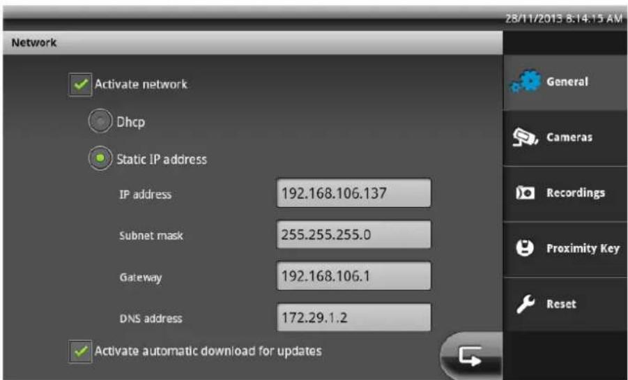
We recommend selecting the DHCP option for internet access (NTP synchronisation). If this causes problems or there is no DHCP server in the network, you can configure a static IP address instead.
| Activate network Activates/deactivates the network port of the Eycasa main unit. | |
| DHCP If this function is activated, your main unit takes its IP configuration from your router (or another network device with a DHCP server). | |
| Manual IP address | If this function is activated, you can make the IP address configuration manually. |
| IP address Enter the IP address here. Make sure that the address you choose is not used by any other device. In private networks, the address is usually 192.168.0.XXX | |
| Subnet mask Enter the subnet mask here. In private networks, the subnet mask is usually 255.255.255.0 | |
| Gateway Enter the gateway address here. Generally, this is the IP address of your router (usually 192.168.0.1). | |
| DNS address Enter the DNS address of your internet provider. Generally, this is the IP address of your router (usually 192.168.0.1). | |

Warning:
Only use the manual IP address settings if you know exactly which values have to be set. If possible, use the "DCHP" option. The Eycasa main unit currently supports the IPv4 protocol.
7.5 Camera settings
The camera settings allow you to pair new cameras in the Eycasa main unit and change the configuration. Depending on the paired camera type, different configuration elements are available.
General camera settings:
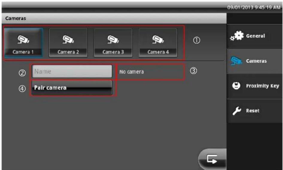
| 1 | Selection of the camera channels 1–4. The currently selected camera is highlighted in blue. |
| 2 | Input field for camera name with a maximum of 12 characters. Choose a suitable name for your camera (such as front door or backyard). |
| 3 | Display of the camera type. If the “No camera” type appears, no camera has been programmed on the currently selected channel. |
| 4 | “Pair camera” starts the setup wizard for new cameras. See item 5, Pairing system components. |
Video door station settings:
![Cameras 09/01/2013 9:49:27 AM Camera 1 Camera 2 Camera 3 Camera 4 Name Eycasa video door station Pair camera Rotate Ring Tone: 1 Camera permanently active Door open time [seconds] Volume video door station [%] 1 2 5 10 10 20 40 60 80 100 General Cameras Proximity Key Reset](/content/2026/06/1168027/images/3de5bde963cd17e13426a2141188ffd1a8497f06fe56469e275313436336e004.jpg)
| 1 | Selection of the doorbell tone. This sound is played on the main unit during doorbell operation. |
| 2 | Setting for the door opening time (RELAY 1) when the door opener is triggered by the main unit or proximity key. |
| 3 | Setting for rotation of the camera image (90° to the left or right) for horizontal installation of the video door station. |
| 4 | Setting for deactivation of continuous transmission of the video image of the video door station. This setting is deactivated in the factory settings in order to avoid constant monitoring. Whenthe setting is deactivated, the video image of the door station is transmitted only during the doorbell ringing process. This setting is not relevant for operation of the door station in battery mode. |
| 5 | Setting of the loudspeaker volume on the video door station. |

Important:
In order to ensure legal compliance, it is recommended that continuous transmission of the video image be deactivated when publicly accessible spaces can be viewed.
Outdoor camera settings:
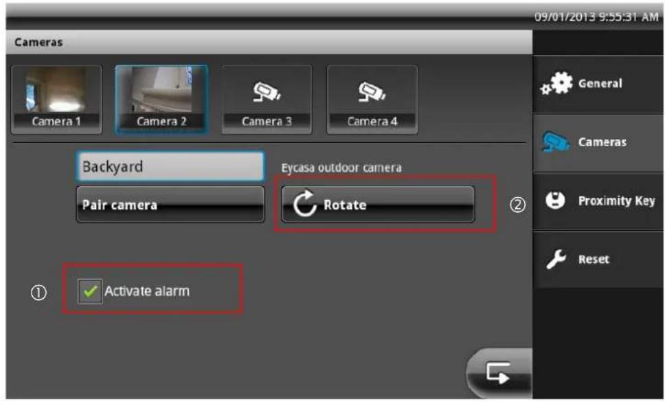
| 1 | Setting for activating/deactivating the event message of the outdoor camera. If the setting is not activated, motion events are not evaluated. |
| 2 | Setting for rotation of the camera image 90° to the left or right in case of outdoor camera installation orientation requiring such rotation. |
Family Care camera settings:
![Cameras 25/11/2013 10:04:25 AM Camera 1 Camera 2 Camera 3 Camera 4 Name Eycasa FamilyCare camera Pair camera Rotate ③ ① Lullaby: 1 Sensitivity Volume FamilyCare camera [%] ② high medium low 10 20 40 60 80 100 General Cameras Recordings Proximity Key Reset](/content/2026/06/1168027/images/f4e3ddd35ec8cccf8194f293afa76edc2d702cb67e1d0a3f5fef099dcbb85894.jpg)
| 1 | Setting the lullaby. This tune is played when you press the “Lullaby” button on the main unit of the Family Care camera. |
| 2 | Voice detection sensitivity setting of the Family Care camera. The higher the set value, the more quickly the camera reacts to sounds, and triggers the VOX alarm. |
| 3 | Setting for turning the Family Care camera image 90° to the left or right if installed to do so. |
| 4 | Loudspeaker volume setting of the Family Care camera. |
7.6 Recording settings
The recording settings menu allows you to set the recording function for your video doort station. Insert an SD card (at least 2 GB / max. 32 GB) in the Eycasa main unit to save video data.
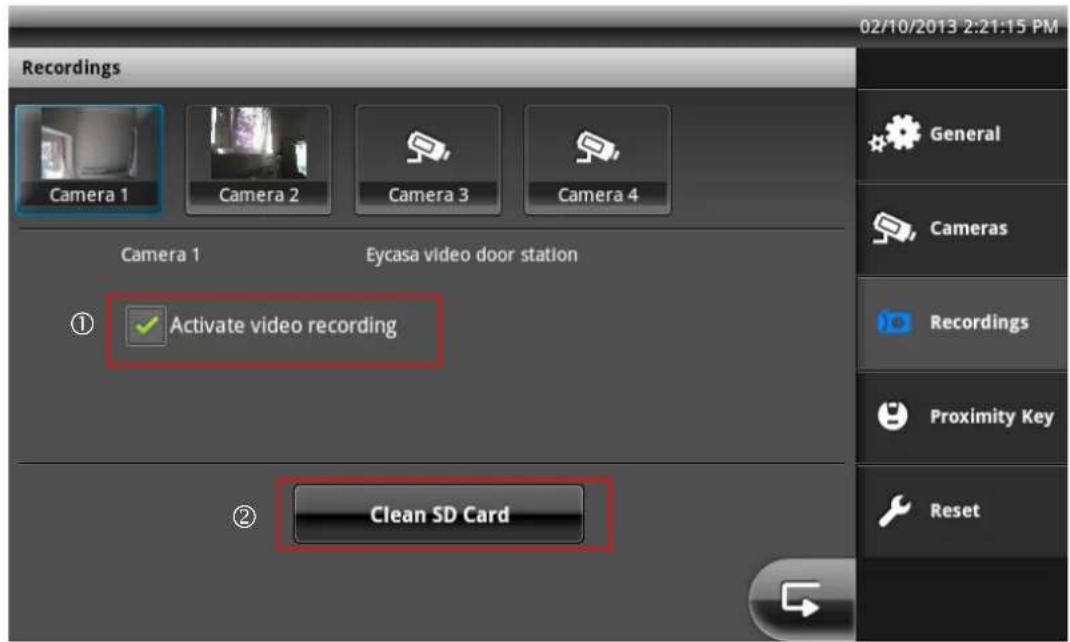
| 1 | Activates/deactivates recording for the selected video door station. |
| 2 | Deletes all data on the SD card that is not relevant for Eycasa. |
You can play the recorded video data directly via the event list if the Eycasa main unit, or play it on your PC. The video data is saved in the \eycasa\videofiles folder on the SD card.
| Important:The recording function operates using the integrated circular buffer of the event list. The circular buffer has a capacity of 500 entries. Once this has been reached, older entries and video data are overwritten.Make sure that the SD card is not pulled out of the main unit while video data is being recorded or played. |
7.7 Proximity key settings
In the "Pair proximity key" menu, you can manage your chip keys. For pairing the individual keys, in addition to activation of the command within the Eycasa software, the key must be held up to the video door station.
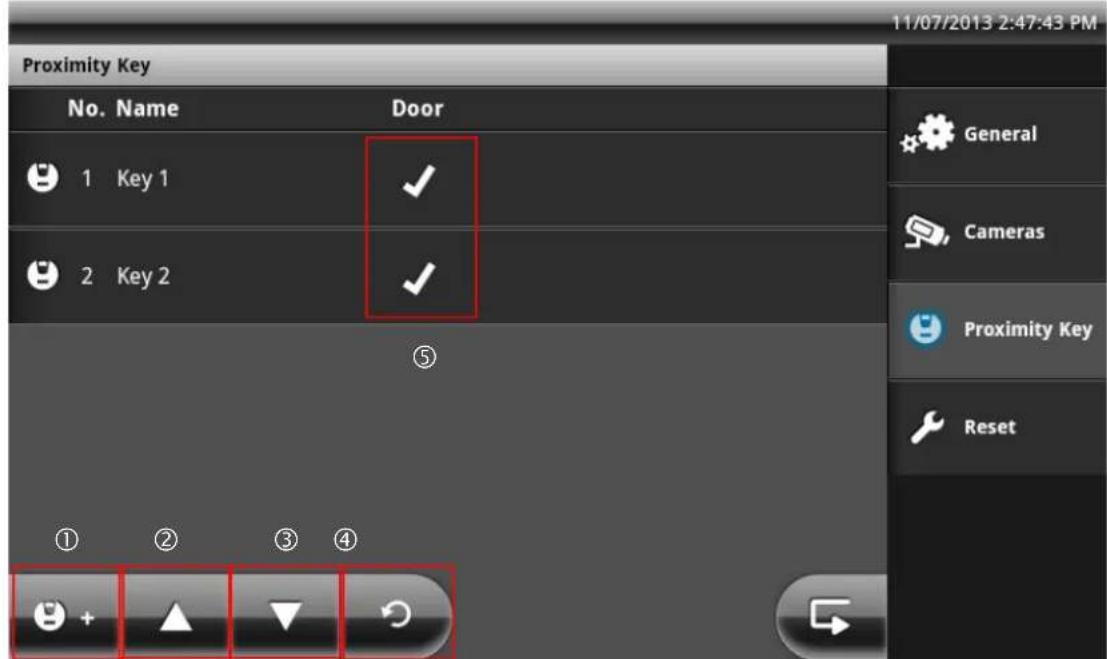
| 1 | Pair a new key with the video door station |
| 2 | Scroll list upwards (for more than 5 chip keys) |
| 3 | Scroll list downwards (for more than 5 chip keys) |
| 4 | Reload the chip key list on the video door station |
| 5 | Chip key status display: X = chip key inactive √ = chip key active |
Pairing the proximity key
Press the "Pair proximity key" button to pair new chip keys on your video door stations. After the "Pair proximity key" button is pressed, pairing mode is activated on all connected video door stations for 120 seconds. Put your chip key into the detection range (marked in red) of the video door station.
| Note:Pairing mode is automatically ended on all video door stations if no chip key is paired during pairing mode. |
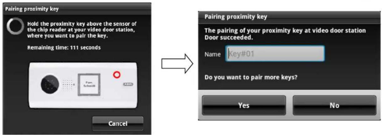
After successful pairing, you can specify a name for the chip key and then pair further keys. If you answer the question with "No", pairing mode is terminated on all video door stations.
Managing proximity keys
Press a key from the list to select it and display the chip key management options.
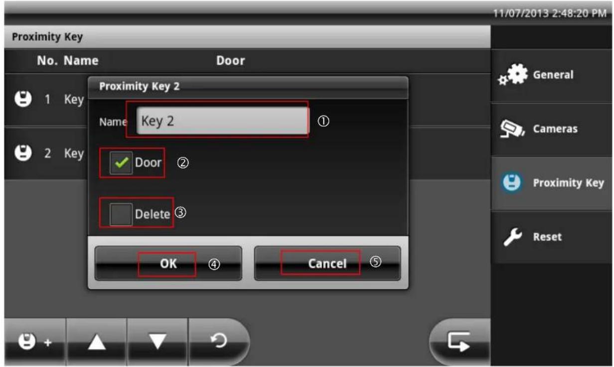
| 1 | Change the chip key name: Change the name of your chip key using the on-screen keyboard. |
| 2 | Change the chip key status: By activating/deactivating the button, you can change the status of the chip key. If the button is deactivated, the key is inactive and cannot be used to open the doors until the status is manually reset to active. Use this option to temporarily block a key. |
| 3 | Delete chip key: If the button is activated, the selected key will be deleted completely after confirming with “OK”. |
| 4 | Save procedure: All entries are saved / carried out. |
| 5 | Cancel procedure: All entries are discarded. |
7.8 Settings on the Eycasa handset
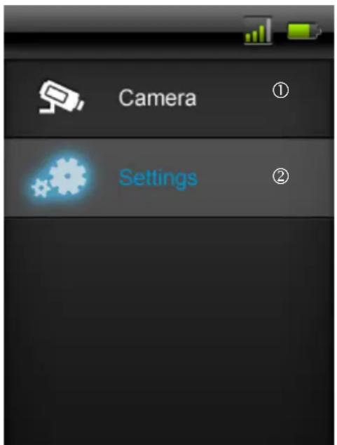
| 1 | Direct access to components which are connected to the Eycasa main unit. |
| 2 | Open the settings for the handset. |
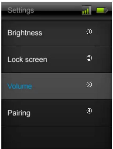
| 1 | Brightness setting for the display, with the levels “Low”, “Medium” and “High”. |
| 2 | Time setting, after which the locked screen is automatically activated. (10s, 30s, 1m, 2m) |
| 3 | Audio-relevant parameter settings (doorbell, loudspeaker, VOX) with the levels “Low”, “Medium” and “High”. |
| 4 | “Pairing mode” menu |
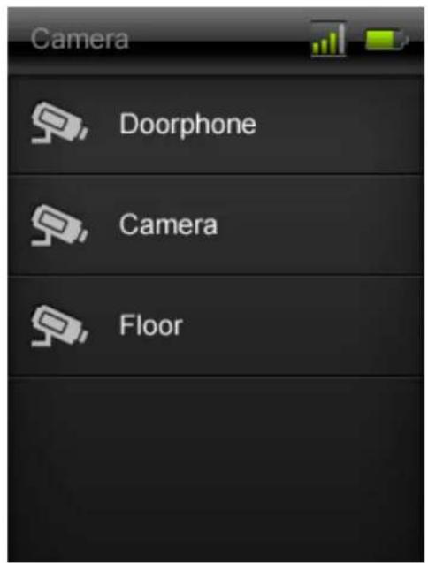
The list visible under “Camera” includes all devices which have been taught in and paired with the Eycasa main unit. The door station and the outdoor camera can be accessed.
The following functional scope is available for manual selection on the respective devices:
a) Door station:
When the door station camera is set to "Camera permanently active", the live image of the door station can be transmitted to the handset. The door opening function is also available. If the door station camera is not permanently activated, then no image is transmitted to the handset. Only the door opening function will be available for selection. To return to the "Camera" list, simply press the red "Back button" on the handset.
b) Outdoor camera:
The video image from the outdoor camera can be accessed using the handset. To do so, simply select the required camera using the handset. To return to the "Camera" list, simply press the red "Back button" on the handset.
7.9 Factory settings
Select "Reset" to reset your Eycasa main unit to the factory settings. The following settings are deleted:
- All settings for doorbell tones are set to the standard settings.
- All camera names are deleted.
- The wireless connection to all connected cameras is deleted.
- All camera settings (alarm, rotation, volume) are deleted.
- The event list is deleted.
- The current PIN is deleted.
- All audio settings are reset to the standard settings.
- The screen saver is set to the standard settings.
- The proximity key is deleted from all video door stations
- The remote connection to the handset is deleted.
After resetting of the settings, the system language must be set again.

Note:
The connected video door stations must be operating on a power supply unit in order to be completely reset.
8. Maintenance and cleaning
8.1 Maintenance
Examine the technical safety of the product regularly, e.g. check the housing for damage.
If it seems that it may no longer be possible to operate the device safely, stop using the product and protect it from unintentional use.
It is likely that safe operation is no longer possible in the event that:
- The device shows signs of visible damage.
- The device no longer works correctly.

For the Eycasa main unit and outdoor camera, take note of the following:
You do not need to perform any maintenance on the product. There are no components to service and there is nothing inside the product to check. Never open it.

For the Eycasa video door station, take note of the following:
If you operate the video door station on batteries, check the state of charge at regular intervals by establishing a voice connection to the main unit. If a battery message appears on the main unit, you should replace them promptly.
8.2 Cleaning
Clean the device with a clean, dry cloth. The cloth can be dampened with lukewarm water if the dirt on the monitor is hard to remove.

Important:
Only use the included antennas for installation.

Do not allow any liquids to enter the device.
Do not use any chemical cleaning products, as they could damage the surface of the housing (discoloration).
9. Disposal
Devices displaying this symbol may not be disposed of with domestic waste. At the end of its service life, dispose of the product according to the applicable legal requirements. Please contact your dealer or dispose of the products at the local collection point for electronic waste.
10. Technical data
| Model number | CASA30100Eycasa video door station |
| Alarm Doorbell signal on main unit | |
| Connectible devices Eycasa main unit | |
| Orientation | Horizontal |
| Operating mode Permanent power supply or battery-operated | |
| Image sensor 1/4" CMOS | |
| Resolution 640 x 480 pixels (VGA) | |
| Lens | 2.5 |
| Horizontal angle of view 120° | |
| Number of IR LEDs 8 IR LEDs | |
| Range of night vision function Approx. 1.5 m | |
| IR angle 120° | |
| IR swivel filter No | |
| Video frequency 2.4 GHz | |
| Video modulation FHSS+GFSK | |
| Video data rate | 2 Mbps |
| Video transmission power | 13.5 dBm |
| Video sensitivity -82 dBm | |
| Audio frequency 1.9 GHz | |
| Audio modulation | TMDA |
| Audio transmission power | < 20 dBm |
| Audio sensitivity -82 dBm | |
| Audio data rate | 64 Kbps |
| Wireless range | 30 m (depending on the site conditions) * |
| Compression | MPEG-4 |
| Frame rate | 20 fps |
| Microphone | Integrated |
| Loudspeakers | 8 Ohm, 2 W x 1 |
| Power supply | 12 V – 24 V AC/DC |
| Battery supply | 6 x 1.5 V AA (CASA30150) |
| Battery life | 6–8 months (when using CASA30150) |
| Power consumption | Max. 800 mA |
| Proximity key | Up to 10 keys can be paired |
| Relay outputs | 2 (potential-free, NO) |
| Installation | Surface mounting |
| IP degree of protection | IP54 |
| Operating temperature | -10 °C – 50 °C |
| Dimensions (W x H x D) | 315 x 135 x 32 |
| Net weight | 600 g |
| Model number | CASA30200Eycasa main unit |
| Connectible devices | Max. 1 x Eycasa video door station, max. 3 x Eycasa outdoor camera |
| Mount | Table mount, wall mount |
| Monitor type | 7" touchscreen LCD |
| Resolution | 800 x 600 |
| Transmission channels | 4 |
| Video frequency 2.4 GHz | |
| Video modulation FHSS+GFSK | |
| Video data rate | 2 Mbps |
| Video transmission power | 13.5 dBm |
| Video sensitivity -82 dBm | |
| Audio frequency 1.9 GHz | |
| Audio modulation | TMDA |
| Audio transmission power < 20 dBm | |
| Audio sensitivity -82 dBm | |
| Audio data rate 64 Kbps | |
| Wireless range 30 m (depending on site conditions) * | |
| Event log 500 | |
| Adjustable alarm tone 5 doorbell tones | |
| Loudspeakers 8 Ohm, 2 W x 2 | |
| Microphone | Integrated |
| Network RJ45 10/100 Mbit Ethernet | |
| Storage medium SDHC card, max. 32 GB | |
| Power supply 12 V DC / 1 A | |
| Power consumption Max. 800 mA | |
| Degree of protection IP30 | |
| Operating temperature -10 °C – 50 °C | |
| Dimensions (W x H x D) 185 x 200 x 100 | |
| Net weight 670 g | |
| Model number | CASA30300Eycasa handset |
| Mount Table mount, wall mount | |
| Monitor type | 3.2" touchscreen LCD |
| Resolution | 320 x 240 |
| Transmission channels | 5 Ch |
| Audio& Video frequency | 1.9 GHz |
| Audio& Video modulation | TDMA |
| Audio& Video transmission power | < 20 dBm |
| Audio& Video sensitivity | -82 dBm |
| Audio& Video data rate | 64 Kbps |
| Wireless range | 30 m (depending on site conditions) * |
| Loudspeaker | 8 Ohm, 1W |
| Microphone | Integrated |
| Power supply | 5 V DC / 1 A |
| Power consumption | Max. 600 mA |
| Degree of protection | IP30 |
| Operating temperature | -10 °C – 50 °C |
| Dimensions (W x H x D) | 74x127x19 |
| Net weight | 230g |
| Model number | CASA30400Eycasa Family Care camera |
| Alarm VOX signal on Eycasa main unit | |
| Connectible devices Eycasa main unit | |
| Operating mode Permanent power supply or battery-powered | |
| Image sensor 1/4" CMOS | |
| Resolution 640 x 480 pixels (VGA) | |
| Focal length 3.27 mm | |
| Horizontal angle of view 54° | |
| Number of IR LEDs 7 IR LEDs | |
| Range of night vision function Approx. 3 m | |
| IR angle 90° | |
| IR swivel filter No | |
| Video frequency 2.4 Ghz | |
| Video modulation FHSS+GFSK | |
| Video data rate 800 kbps | |
| Video transmission power 13.5 dBm | |
| Video sensitivity | -82 dBm |
| Audio frequency 1.9 Ghz | |
| Audio modulation | TMDA |
| Audio transmission power < 20 dBm | |
| Audio sensitivity | -82 dBm |
| Audio data rate | 64 kbps |
| Wireless range | 30 m (depending on site conditions) |
| Video compression | MPEG-4 |
| Frame rate | 20 fps |
| Microphone | Integrated |
| VOX sensitivity | 5 levels |
| Loudspeaker | 8 ohms / 1 x 1 watt |
| DC power supply | 5 V |
| Battery type | 1200 mAh / 3.7 V lithium polymer battery |
| Rechargeable battery running time | 3 hours of continuous operation / 24 hours standby |
| Power consumption | max. 850 mAh |
| IP protection class | IP34 |
| Max. operating temperature | -10 °C – 50 °C |
| Dimensions (W x H x D) | 69 x 117 x 32 |
| Net weight | 500 g |
| Model number | CASA30500Eycasa outdoor camera |
| Frequency | 2.4 |
| Modulation | GFSK |
| Transmission power 16 dBm | |
| Sensitivity | -82 |
| Resolution 640 x 480 pixels (VGA) | |
| Lens | 3.6 |
| Horizontal angle of view 60° | |
| Number of IR LEDs 27 IR LEDs | |
| Range of night vision function Approx. 8 m | |
| IR angle 90° | |
| IR swivel filter Yes | |
| Frequency 2.4 GHz | |
| Modulation FHSS+GFSK | |
| Data rate 2 Mbps | |
| Transmission power 13.5 dBm | |
| Sensitivity -82 dBm | |
| Wireless range 30 m (depending on site conditions) * | |
| Compression | MPEG-4 |
| Frame rate | 20 fps |
| Power supply | 5 V DC / 1 A |
| Power consumption | Max. 650 mA |
| Degree of protection | IP66 |
| Operating temperature | -10 °C – 50 °C |
| Dimensions | 130 x 90 x 27 mm |
| Net weight | 500 g |
* The wireless transmission range depends on environmental factors (e.g. mobile communication masts, high-tension pylons, electrical wires, ceilings and walls, etc.). If conditions are not favorable, the range will be limited.
- Eycasa Door & House Wireless Video System
- Introduction
- Warning as required by § 201 StGB (German Criminal Code):
- Disclaimer
- Explanation of symbols
- Important safety information
- Safety information
- Wireless transmission
- Warnings
- Unpacking the device
- Contents
- Maintenance and cleaning.... 50
- Disposal 50
- Technical data 51
- Intended use
- Eycasa system components
- Features and functions
- Device description
- Description of the Eycasa main unit
- Description of the Eycasa video door station
- Connection examples for an electronic door opener/door bell
- Connection for an electronic door opener:
- Connection for an electronic door bell:
- Description of the Eycasa outdoor camera
- Description of the Eycasa Family Care camera
- Description of the Eycasa handset
- Pairing the system components
- Pairing the Eycasa components in the Eycasa main unit
- Note:
- Important:
- Pairing the Eycasa video door station
- Pairing the Eycasa outdoor camera
- Assigning the Eycasa Family Care camera
- Pairing the Eycasa handset
- Mounting the system components
- Mounting the Eycasa main unit
- Mounting the Eycasa video door station
- Mounting the Eycasa outdoor camera
- Mounting the Eycasa Family Care camera
- Mounting the Eycasa handset
- System operation
- Start-up of the Eycasa main unit
- Sequence:
- Operating the live view
- Event list and event behavior
- Playback of event recordings
- Doorbell event
- Sequence of doorbell ringing:
- Proximity key event
- Motion event
- Sequence of motion detection:
- Family care event
- Voice activation sequence:
- General system settings
- PIN lock settings
- Information:
- Software update settings
- Language settings
- Screen saver settings
- Audio volume settings
- Time and date settings
- Network settings
- Warning:
- Camera settings
- Video door station settings:
- Family Care camera settings:
- Recording settings
- Proximity key settings
- Pairing the proximity key
- Managing proximity keys
- Settings on the Eycasa handset
- Factory settings
- Maintenance and cleaning
- Maintenance
- For the Eycasa main unit and outdoor camera, take note of the following:
- For the Eycasa video door station, take note of the following:
- Cleaning
- Disposal
- Technical data
Brand : ABUS
Model : Eycasa
Category : Intercom