6009 - Security Camera Ansel - Free user manual and instructions
Find the device manual for free 6009 Ansel in PDF.

User questions about 6009 Ansel
0 question about this device. Answer the ones you know or ask your own.
Ask a new question about this device
Download the instructions for your Security Camera in PDF format for free! Find your manual 6009 - Ansel and take your electronic device back in hand. On this page are published all the documents necessary for the use of your device. 6009 by Ansel.
USER MANUAL 6009 Ansel
IP Cam is the most economic and efficient remote monitoring/management solution. It features simple installation, and a user can complete installation without the use of a computer. With a built-in Web server, it can conduct remote image monitoring and management by use of such browsers as IE and Netscape over an LAN or WAN anywhere anytime, so that you can fast master the real-time image conditions in a monitored area.
The single chip of the IP Cam system integrates CPU, CMOS sensor controller, image processor, JPEG codec and Ethernet MAC. In addition, it also supports multiple network protocols such as PPPoE, DHCP, static IP, DDNS, SMTP, FTP and NTP, with cooperation of efficient SDRAM control and SD memory card access. Its built-in TV Out encoder can even display the most common home TV pictures (supporting both NTSC and PAL systems). With the combination of fast hardware motion detection, SD card and infrared LED, it also supports night viewing function. Therefore, it can implement professional security protection for remote monitoring and snapshot in home application.
IP Cam is the best cost-effective solution for you to develop network monitoring products or broadband network cameras. Your choice is surely a sagacious business decision.
Product Application
• IP CAM - Web Server
• IP monitoring - IP DVR
• Network monitoring – real-time remote monitoring
- IP Video Server
System Requirements
Computer system:
- Processor: Intel Pentium III ^® 800 MHz or a processor of the same grade or above
• Memory: 64MB or above (256MB is recommended) - Operating system: Windows 98, Windows 2000 ® or Windows XP ®
- Browser: Microsoft IE 6.0®
• Hard disk: At least 5 GB
• Network: a network with 10/100Mbps Ethernet interface.
Chapter 2 Usage of External Tools
2.1 CAM\_EZ SEARCH
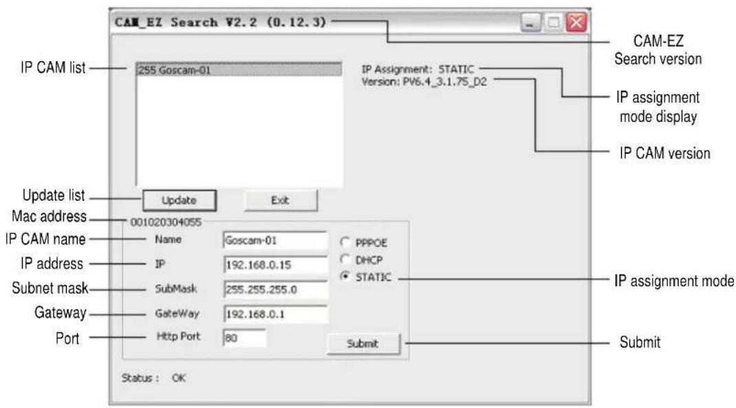
CAM_EZ Search is a search application provided by our company, which can search for online IP CAM in a definite area. By sending an inquiry broadcast packet and receiving an IP CAM response, the window will display the list of all IP CAMs in the network area. Furthermore, it will also provide the function of changing the network settings of the designated IP CAM, such as changing an IP address, and special naming of an IP CAM.
Operating procedures:
1) Start and run the search application CAM_EZ Search.
2) Compare whether the IP values in the PC network and the CAM_EZ Search belong to the same network section: To check the IP address, select Control Panel → Network and Internet Connections → Local Area Connections, right click, and select Properties (P)→ Internet Protocol (TCP/IP) → select Properties (R). If they belong to different network sections, change the IP address of the EZ IPCAM as follows:
- Step 1: Name: The user can define the name of the EZ IPCAM by himself/herself.
- Step 2: IP: IP address of EZ IPCAM; take the IP address of PC (192.168.1.159) as an example, the IP address of the IPCAM can be set to 192.168.1.* (*=1\~254).
• Step 3: SubMask: subnet mask (U), normally set to 255.255.255.0.
- Step 4: GateWay: preset communication gateway. Please change it to be the same as the default gateway (D) set by the PC network.
- Step 5: HTTP Port: Http communication port, set to 80 by default;
3) After the setting is completed, click
4) Click
5) Click the name in the list twice, to automatically start the browser and enter the network monitoring picture.
CAM_EZ Search is shown as follows:
2.2 Operation of the Button
During normal system operation, press and hold the
2.3 TV\_OUT Function
The operational procedures of the TV_OUT function are as follows:
1) Connect the IP Cam to a TV set;
2) When the IP CAM is off, press and hold the
Note:
The reset button is the < AV SET > button.
Chapter 3 Operational Mode
3.1 System Login
System login is used to identify and verify an authorized user who is allowed to enter the system and conduct related functions provided by the system. The system provides two levels of management modes: Administrator and General User. After successful login, the user can start network monitoring and setting as follows:
1) Step 1: Start the login window. Please refer to the following mode:
- Mode 1: Run CAM_EZ Search, double click on the corresponding IP CAM name in the IP Cam list.
- Mode 2: Start the IE explorer, and directly enter the IP address of the IP CAM in the Address bar.
2) Step 2: The system login window will appear in the IE, as follows:
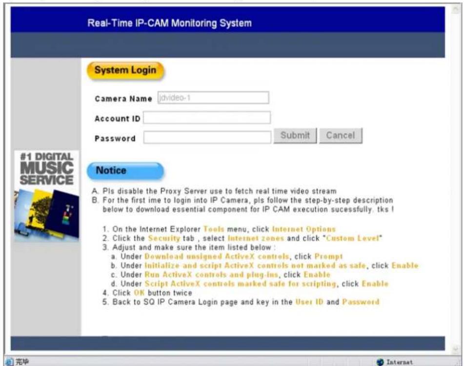
3) Step 3: Enter the Account ID and Password. The default Account ID is "admin", and the default Password is "password". Click
4) Step 4: Click
3.2LiveView
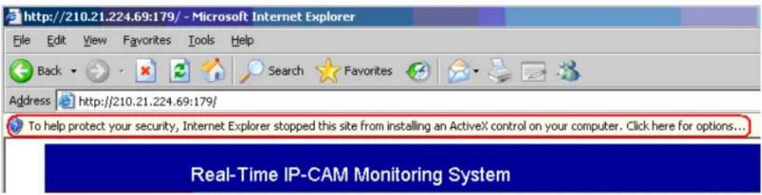
During the first use of the IP CAM, you need to modify the IE security setting parameters (for details refer to the setting procedures in Section 3.2.1); otherwise, the following prompt may appear in the IE, causing failure in image detection. After successful startup of the security parameter setting of the IP CAM for the first time, you do not need to conduct any setting any longer.
3.2.1 Procedures for Modifying IE Security Setting Parameters
Step 1: In an IE window, select the Tools → Internet Options menu;
Step 2: Click the Security tab and then click
1) Download unsigned ActiveX controls: Click Prompt
2) Initialize and script ActiveX controls not marked as safe: click Enable
3) Run ActiveX controls and plug-ins: click Enable
4) Script ActiveX controls marked safe for scripting: click Enable
Step 3: Click

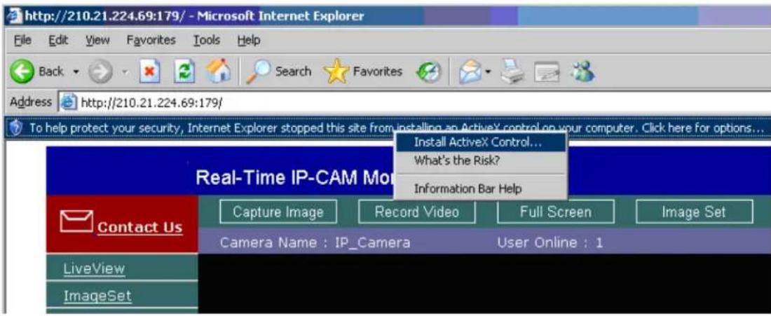
Step 4: Click the Prompt column, select Install ActiveX Controls from the pop-up menu, and you can browse for the first time after automatic refresh.
3.3 Take a Shot
This function can take a shot from PC images and store it in the PC by use of shortcut buttons.
Operating procedures:
Step 1: Enter theLiveViewlist, and the real-time monitoring window is as follows:
Step 2: Select an appropriate image, press and hold the
Step 3: Move the cursor to the monitoring image picture, and click (or press and hold the
Step 4: Release the
Step 5: Click to select the
Chapter 4 Usage of Image Function
Move the cursor to a real-time monitoring image and right click, and at this moment four options appear:

• Image: Adjusts image parameters;
• Record: Sets and records animation files in AVI format;
- Zoom: Zooms in an image in a selected box in digital mode;
• Motion Detec Set: Sets motion detection parameters.
The settings will be detailed respectively in the following sections.
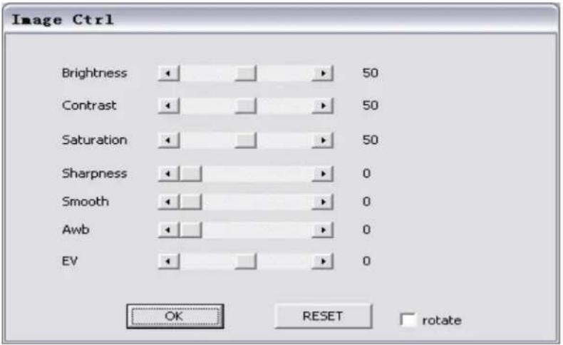
4.1 Image Adjustment
Click to select Image, the following window appears (corresponding to the
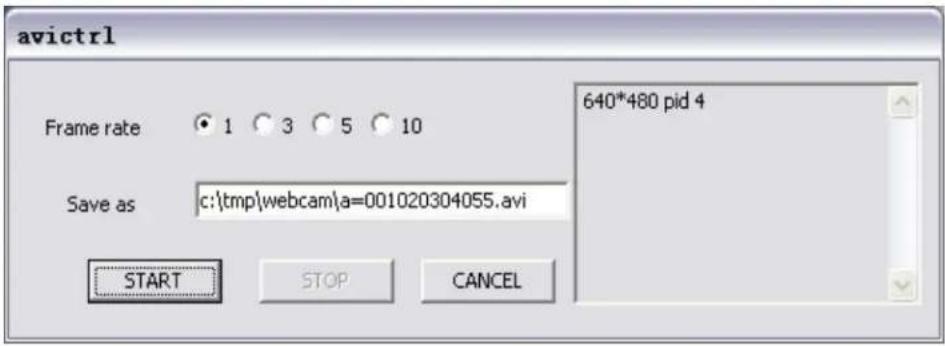
4.2 AVI Record Setup
Click to select Record, the following window appears (corresponding to the
4.3 Zoom Display
Click to select Zoom, the following window appears. Move the mouse to the monitoring image, click and hold your mouse, drag your mouse in the image area to be zoomed in, and release your mouse, and the selected image area will be zoomed in.

4.4 Motion Detection Setup
Set the environmental parameters in the case of Motion Detection (MD) trigger events, including the first group (red) and the second group (green). Please refer to the enable/disable of related options in the Event Trigger tab. You may make the following settings in the enabled mode:
- Reset MD range: Select motion_detec → 1, click and hold your mouse (in this case the upper left corner of the MD range is displayed), drag your mouse to select a range, and release your mouse to make resetting.
- Cancel MD: same as above, but you may only need to click and hold your mouse, and then release it to cancel MD.
- Motion_detc_set: Set MD sensitivity. The default value is 15. That is, the MD will be started in the case of 15% change in the MD range. The lower the value, the higher the sensitivity.
Upon MD startup, the prompt "Motion_Detec Warning!!" will appear on the upper left corner of the window due to the MD change of MD1 or MD2, as shown in the following figure:
Note:
- If the image resolution is 640x480 / 320x240, you may select a framed trigger range at will.
- If the image resolution is 160x120, the trigger range is the entire image in a fixed manner.


4.5 Max Size
If the monitoring image resolution is 320*240 or 160*120, click the
4.6 Audio On/Off
The
- The
- The

Chapter 5 Description of Advanced Functions
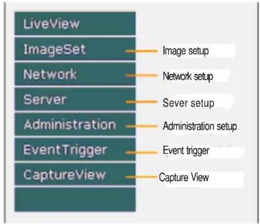
This chapter describes the specific functions of the functional menus in the left of the main window.
5.1 Image Setup
The ImageSet window is shown in the figure below:
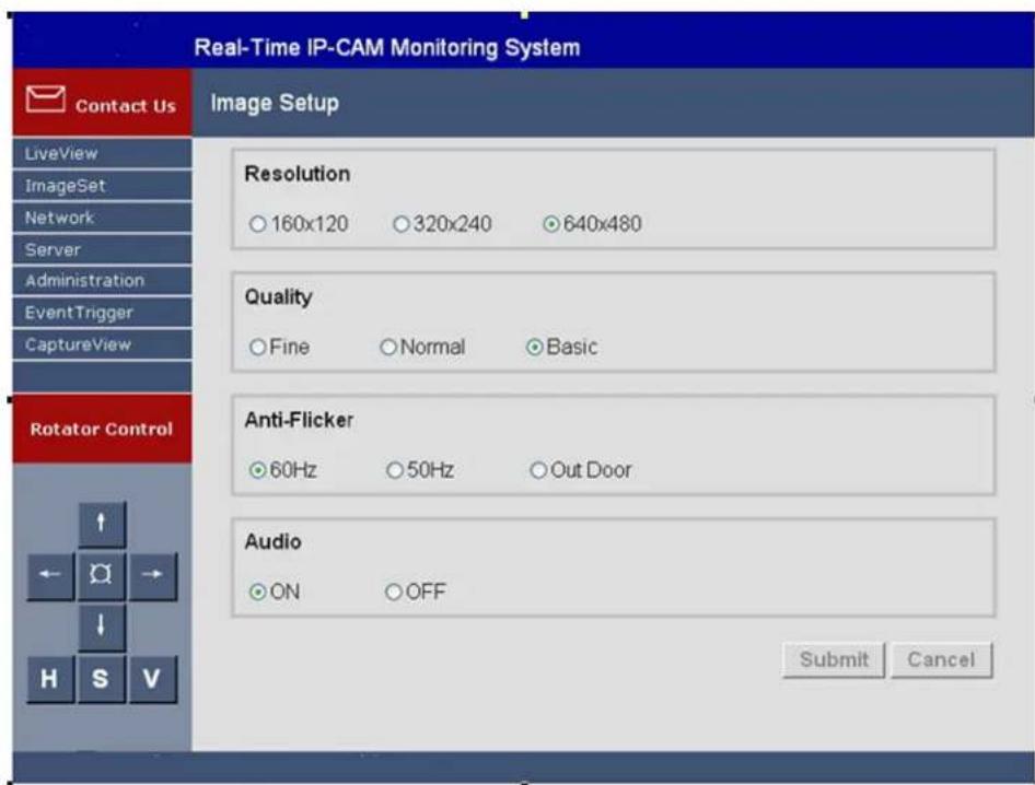
In this window, the user can perform the following settings:
- Resolution: Image output resolution; there are three options: 160×120, 320×240 and 640×480, and 320×240 by default
- Quality: Image quality; there are three options: Fine, Normal, and basic; the default value is Basic.
- Anti-Flicker: Anti-flicker power frequency; there are three options: 60Hz, 50Hz, and Out Door; the default value is 60Hz. Please select the Outdoor option when taking a picture outdoors.
• Audio: Audio output switch; the default value is off.
Operating procedures:
- Step 1: Click ImageSet to enter this menu.
- Step 2: Set the parameters properly and then click
. - Step 3: To cancel the settings, click
.
5.2 Network Setup
The Network window is shown in the figure below, including:
• IP Assignment: IP assignment mode, including Static, DHCP and PPPoE
- PPPoE setting
• Port setting of Http Server
- DNS setting
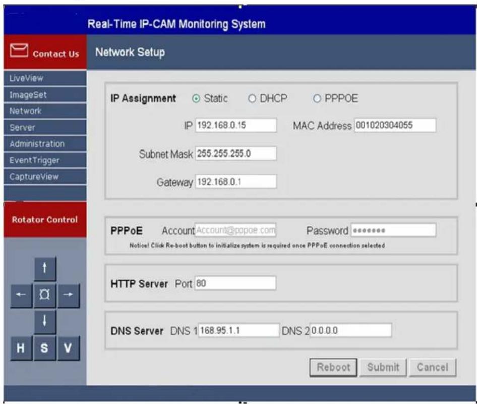
5.2.1 IP Assignment
This option can be used to change the network connection mode of IP CAM. The preset mode is Static.
The MAC Address field shows the MAC address of the IP CAM.
- If it is set to Static, enter the following parameters:
1) IP Address: IP address of the IP CAM
2) Subnet Mask: Subnet mask, preset to 255.255.255.0
3) Gateway: Preset communication gateway
- If it is set to DHCP, it is not required to set the above parameters, but it is necessary to set the IP address of the DHCP Server in the Server menu.
- If it is set to PPPoE, it is necessary to enter the correct ID and Password. For details, refer to Section 5.2.2.
5.2.2 PPPoE
The option can be used to set the dial-up access settings in PPPoE IP assignment. In general, enter a correct ID Account and Password. It must cooperate with the ISP settings.
Operating procedures:
- Step 1: Enter a correct ID in the Account text box.
- Step 2: Enter a correct password in the Password text box.
• Step 3: Click.
Note:
Since PPPoE IP address is dynamically assigned by an ISP, the IP CAM may have a different IP address in each time. It is recommended that an IP router be configured for dial-up connection of PPPoE online settings or DDNS setting, to avoid the failure in finding the IP CAM.
5.2.3 HTTP Server
The option is used to designate the port through which the connection to the built-in Web Server (or HTTP Server) of the IP CAM is made by the HTTP protocol. The default port is 80.
5.2.4 DNS Server
It is used to set the IP address of the DNS (Domain Name Server) Server. In this way, the http name (such as myIPCAM.XXX) can be used to replace the IP address of the IP CAM for easy memory. DNS1 is preset to 168.95.1.1 (Hinet). It will automatically connect to DNS2 is the connection fails.
5.3 Server Setup
This window is used to set the parameters of the IP CAM related to the server, as shown in the figure below:
5.3.1 Mail Server
It is used to set the parameters related to the mail server and the sending of mails with images. It depends on whether the MAIL Image setting in Section 5.5 EventTrigger is enabled. The event-triggered images will be sent to the designated e-mail address by e-mails. The system supports SMTP Server.
Setting steps:
- Step 1: IP/Host: Enter the IP address of the Mail Server or Http address.
• Step 2: Mail From: Enter the e-mail address of the sender.
• Step 3: Receipt to: Enter the e-mail address of the recipient.
• Step 4: Account ID: Enter the Account ID for login to the mail host. - Step 5: Password: Enter the password for login to the mail host.
- Step 6: Authorization: Indicates whether the mail host will perform authentication.
• Step 7: Click.
5.3.2 FTP Server
It is used for the settings related to FTP (File Transfer Protocol) server. It depends on whether the MAIL Image setting in Section 5.5 EventTrigger is enabled. The event-triggered images will be transferred to the designated FTP Server in FTP mode. This system supports Port Mode and Passive Mode.
Setting steps:
- Step 1: IP/Host: Enter the IP address of the FTP server or HTTP address.
- Step 2: Port: Enter the designated port number of the FTP server.
• Step 3: Account ID: Enter the account ID for login to the FTP host. - Step 4: Password: Enter the password for login to the FTP host.
• Step 5: Set the FTP transfer mode to Port Mode or Pasv Mode. - Step 6: Click
.
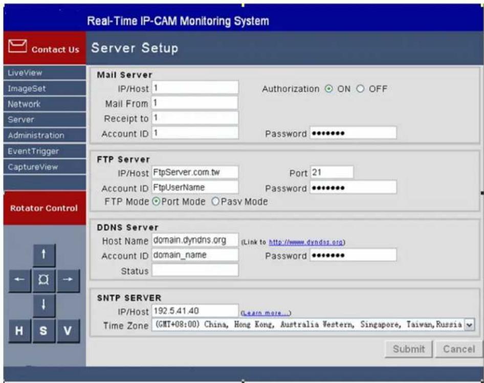
5.3.3 DDNS Server
DDNS (Dynamic Domain Name Server) provides dynamic DNS settings. With the designated DDNS server, pre-entered HTTP address, and related settings, the IP CAM using PPPoE dial up connection (with dynamic IP) can only use the http address (such as sqipcam.dyndns.org) to implement connection, which is easy to memorize and facilitates the view of IP CAM without a fixed IP address.
Operating procedures:
- Step 1: Register a group of user accounts, passwords and Http address in the website providing DDNS service (like http://www.dyndns.org);
- Step 2: Host Name : Enter the website, account and password applied with the address (IP address or HTTP address) of the DDNS host respectively in the fields of Host Name, Account ID, and Password;
- Step 3: Account ID: Enter the account ID for login to the DDNS host;
- Step 4: Password: Enter the password for login to the DDNS host;
- Step 5: Status: Automatically display the status of connection with the DDNS host;
- Step 6: Click
.
5.3.4 SNTP Server
NTP (Network Time Protocol) server is the time server, which provides time calibration function for IP CAM.
Setting steps:
- Step 1: IP/Host: Enter the IP Address or HTTP address of the NTP server;
- Step 2: Select a time zone in the Time Zone drop-down list box.
- Step 3: Click
.
5.4 Administration Setup
This window is used to set IP CAM name, administrator account and password, and general user account and password. An administrator can use all functions and settings of the IP CAM. A general user can only use theLiveView function and cannot set any parameters, as shown in the figure below:
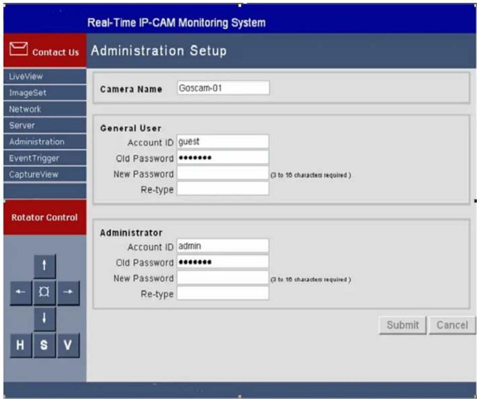
5.4.1 Camera Name: Set the Name of IP CAM
The name set here will be displayed in the upper part of the image for identification.
5.4.2 General User: Set the Account and Password of General User
Setting steps:
• Step 1: Account ID: Enter the login name of the IP CAM;
• Step 2: Old Password: Enter the old password;
• Step 3: New Password: Enter the new password;
- Step 4: Re-type: Enter the new password again for verification;
• Step 5: Click
5.4.3 Administrator: Set the Administrator Account and Password
Setting steps:
• Step 1: Account ID: Enter the login name of the IP CAM;
• Step 2: Old Password: Enter the old password;
• Step 3: New Password: Enter the new password;
- Step 4: Re-type: Enter the new password again for verification;
• Step 5: Click
5.5 Event Trigger
This window is for event trigger settings and display, as shown in the figure below:
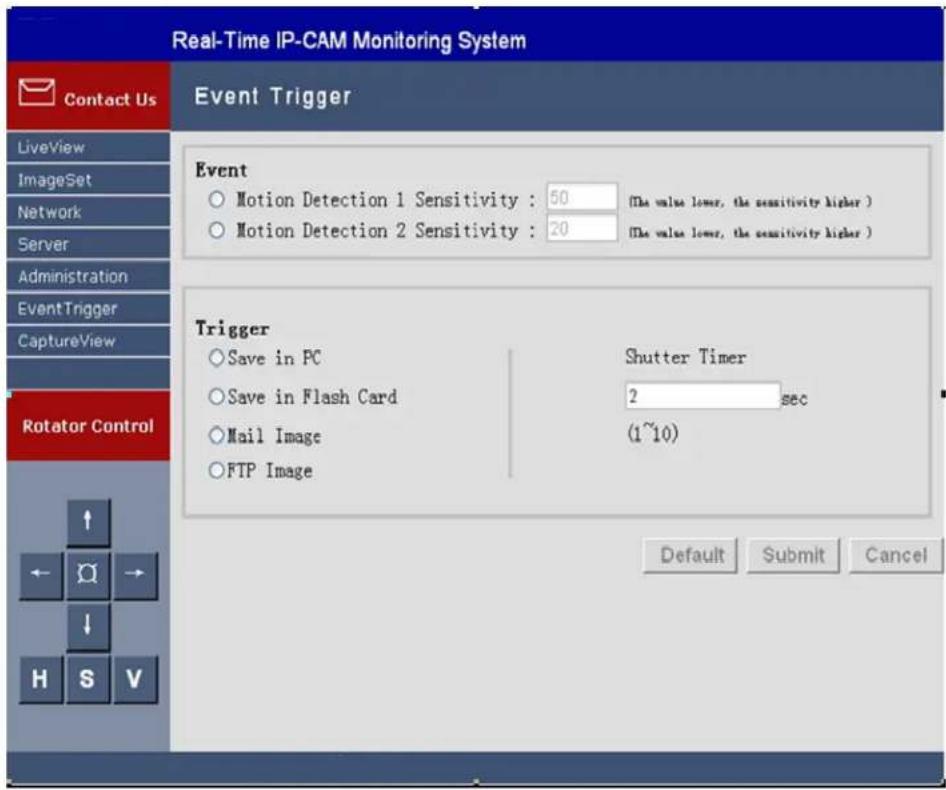
5.5.1 Event
It is used to set the triggering events, including:
- Motion Detection 1
- Motion Detection 2
Either group of trigger input signal can be enabled.
Setting steps:
- Step 1: Enable either group of events (MD will automatically display the trigger sensitivity);
• Step 2: Clickupon confirmation; or - Step 3: Click
to return to the original settings (none enabled).
Note:
If any event item is enabled, Save In PC will automatically be enabled and will be saved to the directory of C:\tmp\webmd.
5.5.2 Trigger
It is used to set the event trigger image transfer mode, including:
- Save in PC: Save image files to a PC.
- Save in Flash Card: Save image files to SD memory card.
- Mail Image: Send event trigger image files by e-mail.
- FTP Image: Transfer event trigger image files in FTP mode.
- Shutter Timer: Event trigger image capture interval, 2 seconds by default.
Note:
The capacity of the SD memory card shall not be less than 1 GB.
5.6 Capture View
The view includes:
• PC: Static images manually captured in LiveView
- FlashCard: Static images automatically captured in LiveView when MD is enabled
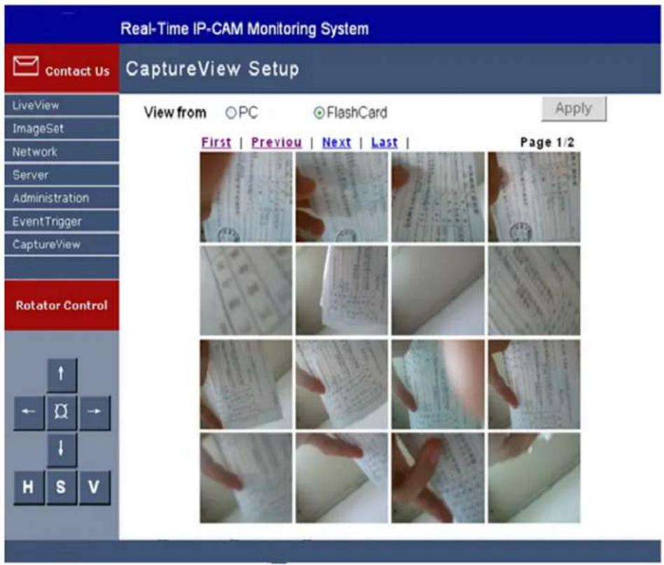
Operating procedures:
- Step 1: Select CaptureView to enter this manual. The fault value is PC. A maximum of 48 thumbnail images can be previewed in three pages.
- Step 2: It can be read from a PC or a SD memory card, deepening on the setting, and then click
. - Step 3: Move the cursor to the designated thumbnail image and select it with the mouse. You can then view the image in preset size.
Chapter 6 Connecting IP Camera to the Internet
The user has to set parameters of the IP Camera before it is put into normal use. All functions of the IP Camera will be available only when parameters of the IP Camera have been properly set and it is connected to the Internet. The installation procedures of the IP Camera may vary with specific network connection conditions of the user.
Parameter setting of IP Camera covers two major steps: 1) IP Camera initialization, and 2) access to the Internet, as detailed below:
Step 1: IP Camera Initialization
1) Connect the IP Camera to the power supply and then connect it to the PC of the user with the supplied crossover cable (marked as Intersect ant cable). Turn on the power switch of the IP Camera.
2) Search the IP Camera connected with the user PC with the CAM_EZ Search tool included in the CD-ROM and set network settings of the IP Camera. The operating procedures are shown in Section 2.1.
Note:
If the user PC is in a LAN, the user can also connect the IP Camera to an idle port of the switch with the supplied straight-through cable (marked as IP Network cable). The setting methods are the same as above.
Step 2: Access to the Internet
Upon the completion of settings in step 1, the user can view the monitored pictures of the IP Camera in the LAN. If the user plans to connect the IP Camera to the Internet to perform remote monitoring, it is necessary to perform further settings.
At present, there are different Internet access modes. The settings of the IP Camera vary with the Internet access modes. Two common access methods are described as follows:
Method 1: Directly connected to the Internet through ADSL Modem
IP Camera provides built-in support for PPPoE and DDNS network protocols. The user can directly connect the IP Camera to the ADSL Modem to access the Internet.
The setting method is as follows:
1) Upon completion of settings in Step 1, open the browser in the PC and log in to the IP Camera.
2) Enter the Server setting page and set the account and password in the DDNS Server field (It is necessary to apply for a DDNS service account in the link on the Server page), and click
3) The Network setting page appears. Select PPPoE for IP Assignment, set the account and password for the Internet access in the PPPoE field, and then click
4) Turn off the power of the IP camera, and connect it to the network port of the ADSL Modem with the crossover cable.
5) Turn on the power of the ADSL Modem, and switch on the IP Camera only when the link indicator light of the Modem lights up. Upon the completion of dial-up, the user can visit the IP Camera from any PC connected with the Internet. To visit the IP Camera, enter the set dynamic domain name in the Address bar of the browser.
The connection diagram is shown as follows:
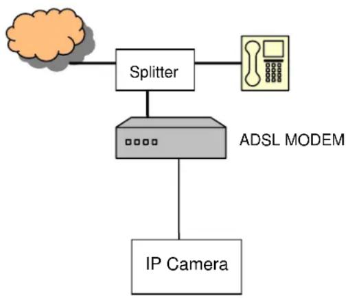
flowchart
graph TD
    A["Cloud"] --> B["Splitter"]
    B --> C["ADSL MODEM"]
    C --> D["IP Camera"]
    B --> E["Phone Icon"]
Method 2: Connected to the Internet through LAN
To connect the IP Camera to a LAN and to access the Internet through the same ADSL broadband line shared with other PCs in the LAN, use an ADSL Modem with routing function and a switch. The IP Camera and other PCs can be connected to the switch to form a small LAN. Connect the ADSL Modem to the switch.
The setting method is as follows:
1) Configure the IP Camera according to step 1.
- IP assignment mode: Select the STATIC option and set an IP address in the same network segment of the ADSL Modem (for example, if the default IP address of the ADSL Modem is 192.168.1.1, set the IP address of the IP Camera to 192.168.1.2).
- Subnet mask: Sets to 255.255.255.0.
- Default gateway: Sets to the IP address of the ADSL.
2) Configure ATM setting options of the ADSL and enter the PPPoE dial-up account and password.
- Enter the IP address of the ADSL Modem in the Address bar of the browser, and then enter account and password in the dialog box appeared to enter the Modem setting page.
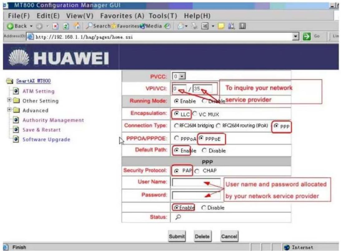
- Enter the ATM setting page of the Modem and set ATM parameters: VPI/VCI values to be queried from local telecom service provider; encapsulation type is LLC; connection type is PPPoE; security protocol is PAP.
- Enter the ADSL account and password in the user name and password fields, and then click
.
3) Set the NAT function of the ADSL Modem. - Enter the Network Address Translation (NAT) setting page of the ADSL Modem.
- Select the option of adding new rules, select REDIRECT for Rule Flavor and TCP for Protocol.
- Set destination port and local port to 80, set local address to the IP address of the IP Camera, for example, 192.168.1.2, and set the IP address of the public network to 0.0.0.0.
4) Enter the Server setting page and enter account and password in the DDNS Server field ((It is necessary to apply for a DDNS service account in the link on the Server page), and click.
The connection diagram is shown as follows:
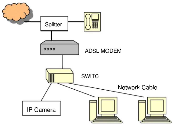
flowchart
graph TD
    A["Cloud"] --> B["Splitter"]
    B --> C["ADSL MODEM"]
    C --> D["Switch"]
    D --> E["Network Cable"]
    D --> F["IP Camera"]
Note:
In the above figure, the interconnection between the switch and the ADSL Modem depends on the port of the switch in use: If it is connected to a common port of the switch, use the straight-through cable; if it is connected to the UPLINK port of the switch, use the cross-over cable.
In addition to the above connection methods, the user can also adopt the ADSL without routing function plus a router to enable the IP Camera and other PCs in the LAN to share the broadband line to access the Internet.
The connection diagram is shown as follows:
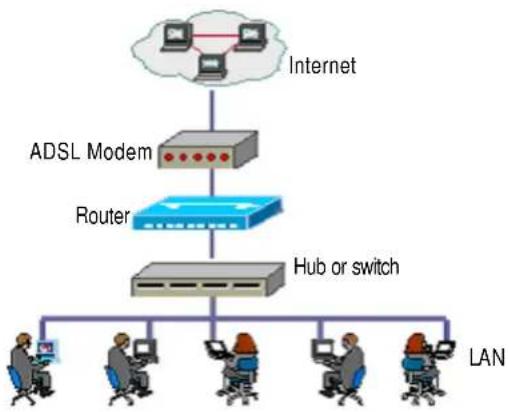
flowchart
graph TD
    A["Internet"] --> B["ADSL Modem"]
    B --> C["Router"]
    C --> D["Hub or switch"]
    D --> E["LAN"]
    E --> F["Computer 1"]
    E --> G["Computer 2"]
    E --> H["Computer 3"]
    E --> I["Computer 4"]
    E --> J["Computer 5"]
To make the IP Camera accessible to Internet users, it is necessary to set the NAT function of the router and to map the IP Camera to the 80 port of the public network. For detailed setting methods, see Appendix 2.
Appendix 1
Example of settings of Huawei MT800:
Enter 192.168.1.1 (default IP address) in the Address bar of the IE Explorer. Enter the user name (admin) and the password (default value: admin) to open the setting window of the MT800.
1) Setting ATM
2) Setting NAT
Select NAT from Other Settings and click
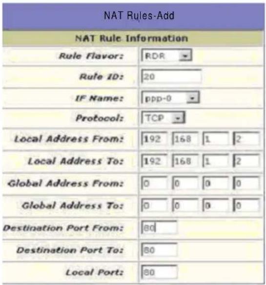
Select REDIRECT for Rule Flavor and TCP for Protocol. Enter the IP address of the IP Camera 192.168.1.2 as the local address, and set the starting destination port and the ending destination port to 80. Click
- Select Save & Reboot in the left of the window, and select Save→Submit, and Reboot→Submit in turn. The setting is complete when the ADSL reboots.
Appendix 2
Example of settings of a Cisco router:
1) After the router has reloaded, enter enable mode again.
Router>enable Router#
2) Configure service timestamp to properly log and display debug output in the troubleshooting section.
Router#configure terminal Router(config)#service timestamps debug datetime msec Router(config)#service timestamps log datetime msec Router(config)#end
3) Disable logging console on your Cisco DSL Router to suppress console messages that may be triggered while you are configuring the router.
Router#configure terminal Router(config)#no logging console Router(config)#end
4) Configure IP routing, IP subnet-zero, and IP classless to provide flexibility in routing configuration options.
Router#configure terminal Router(config)#ip routing Router(config)#ip subnet-zero Router(config)#ip classless Router(config)#end
5) Configure global Point-to-Point Protocol over Ethernet (PPPoE) parameters.
Router#configure terminal Router(config)#vpdn enable Router(config)#no vpdn logging Router(config)#vpdn-group pppoe Router(config-vpdn)#request-dialin Router(config-vpdn-req-in)#protocol pppoe Router(config-vpdn-req-in)#end
6) Configure an IP address and subnet mask on the Cisco DSL Router Ethernet interface.
(Optional) Enable NAT inside on the Ethernet interface.
Router#configure terminal Router(config)#interface ethernet 0 Router(config-if)#ip tcp adjust-mss 1452/ip adjust-mss 1452 Router(config-if)#ip address 192.168.1.2 255.255.255.252 Router(config-if)#ip nat inside Router(config-if)#no shut Router(config-if)#end
7) Configure the ATM interface of your Cisco DSL Router with an ATM permanent virtual circuit (PVC), encapsulation type, and Dialer pool.
Router#configure terminal Router(config)#interface atm 0 Router(config-if)#pvc 0/35 (Guizhou Province) Router(config-if-atm-vc)#pppoe-client dial-pool-number 1 Router(config-if-atm-vc)#no shut Router(config-if-atm-vc)#end
8) Configure the Dialer interface of your Cisco DSL Router for Point-to-Point Protocol over ATM (PPPoA) to enable a dynamic IP address to be assigned.
(Optional) Enable NAT outside on the Dialer interface.
Router#configure terminal Router(config)#interface dialer 1 Router(config-if)#ip address negotiated Router(config-if)#mtu 1492 Router(config-if)#no ip directed-broadcast Router(config-if)#ip nat outside Router(config-if)#encapsulation ppp Router(config-if)#dialer pool 1 Router(config-if)#ppp auth chap hostname heiye Router(config-if)#ppp auth chap password heiye Router(config-if)#ppp auth pap sent-username heiye password heiye Router(config-if)#end
9) Configure a default route using Dialer1 as the outbound interface.
Router#configure terminal Router(config)#ip route 0.0.0.0 0.0.0.0 dialer1 Router(config)#end
10) Configure global NAT commands on the Cisco DSL Router to allow sharing of the dynamic public IP address of the Dialer interface.
Router#configure terminal Router(config)#ip nat inside source list 1 interface dialer1 overload Router(config)#access-list 1 permit 192.168.1.3 0.0.0.255 Router(config)#end
11) Optional Configurations
NAT Pool. if additional IP addresses have been provided by your ISP.
Router(config)#ip nat inside source list 1 pool ciscooverload Router(config)#ip nat pool cisco 200.1.1. 200.1.1.254 netmask 255.255.255. 0 Router(config)#end
12) Static NAT. if Internet users require access to internal servers.
Router(config)#ip nat inside source static tcp 192.168.1.5 80 200.1.1.5 80 extendable Router(config)#end
13) (Optional) Configure the Cisco DSL Router as a DHCP server with a pool of IP addresses to assign to hosts connected to the Ethernet interface of the Cisco DSL Router. The DHCP server dynamically assigns an IP address, Domain Name Server (DNS), and the default gateway IP address to your hosts.
Router#configure terminal
Router(config)#ip dhcp excluded-address 192.168.21.2(E0 ip address)
Router(config)#ip dhcp pool wang
Router(dhcp-config)#network 192.168.1.2 255.255.255.0
Router(dhcp-config)#default-router 192.168.1.2
Router(dhcp-config)#dns-server 202.98.198.168 202.98.192.68
Router(dhcp-config)#end
14) Enable the logging console on the Cisco DSL Router, and write all the changes to memory.
Router#configure terminal
Router(config)#logging console
Router(config)#end
*Jan 1 00:00:00.100: %SYS-5-CONFIG_I: Configured from console by console
Router#write memory/copy run start
Building configuration... [OK]
Router#show run
Router#show ip int brief
to view the IP interface status.