6102 - Security Camera Ansel - Free user manual and instructions
Find the device manual for free 6102 Ansel in PDF.

User questions about 6102 Ansel
0 question about this device. Answer the ones you know or ask your own.
Ask a new question about this device
Download the instructions for your Security Camera in PDF format for free! Find your manual 6102 - Ansel and take your electronic device back in hand. On this page are published all the documents necessary for the use of your device. 6102 by Ansel.
USER MANUAL 6102 Ansel
Network Video Recorder
Quick Installation Guide v1.5.0
Model: NVR4CH/8CH/16CH
Contents
Purpose 3
Package Contents 3
Install Hard Disk 4
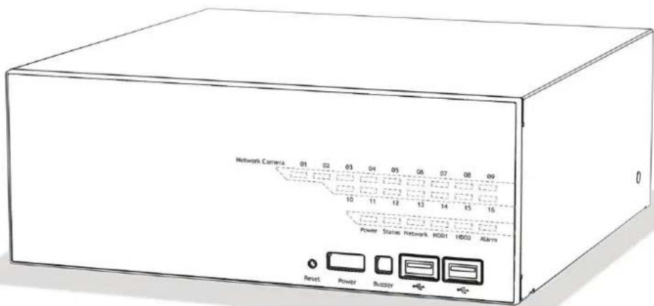
System Overview (Front) 7
I/O Ports and RS-485 (Rear) 9
LEDs Definition 10
Connect to the NVR 12
Set up Password 16
Add a Camera 17
Recording Configurations 19
UPS Configurations 23
Purpose
This document provides information for installing the Network Video Recorder on your network. The information included in this document should be sufficient for users to quickly setup the device and start the live video monitoring. Users should also be able to perform basic troubleshooting with information provided in this document. For all other aspects of using this product, please consult the user's manual available on the CD
Package Contents
• Network Video Recorder
- Power cord
- Ethernet cable
• Printed Quick Installation Guide
• Printed Warranty Card
- CD with Adobe Acobat Reader/Quick Installation Guide/User's Manual/NVR Media Player/NVR Search Utility/CMS software
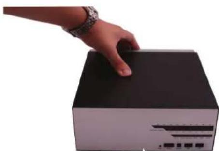
Install Hard Disk
Start by removing the screws on the side:
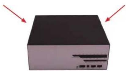
natural_image
3D rendering of a black rectangular electronic device with two red arrows pointing to its top surface (no text or symbols visible)
natural_image
Solid black rectangular block with a white arrow pointing downward and a small symbol at the bottom (no text or symbols present)Push the top housing forward

natural_image
Hand pressing a black box with an arrow pointing upward (no text or symbols visible)Then lift it up

natural_image
Hand pointing at a black 3D object with an upward arrow, no text or symbols visible• The NVR supports SATA I or SATA II hard disks
- The NVR supports max. 1.5TB per hard disk and it supports total of 2 hard disks (3TB)
There is a cable connected between the fron LED board and the main board
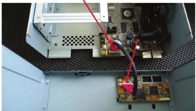
natural_image
Interior view of an electronic device showing a circuit board with connected components and red cables (no visible text or symbols)You can remove it from the main board or simply put the top housing on the side like shown below:
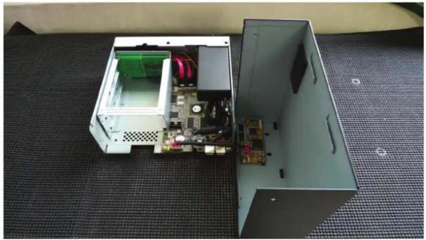
natural_image
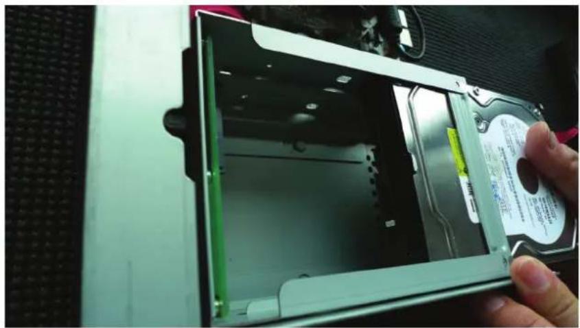
Interior view of an open electronic device with exposed circuit board and accessories, placed on a textured mat (no text or symbols visible)Next, slide the hard drive into the tray:
natural_image
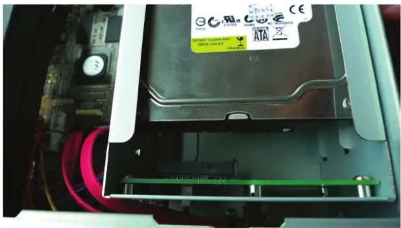
Close-up of a hand inserting a hard disk into a computer case, showing internal components and a label (no readable text or symbols)Make sure the SATA connectors are aligned with each other correctly
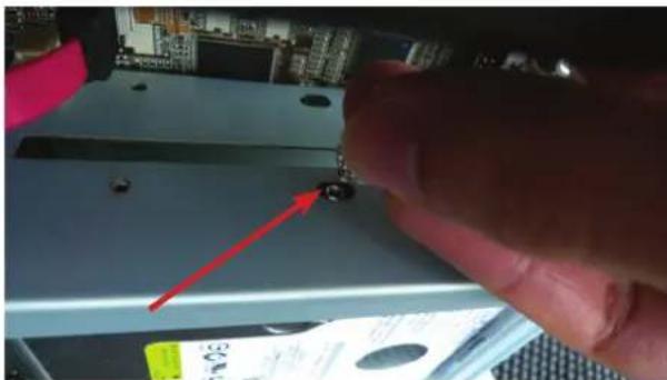
Secure the hard drive with the tool-less screw provided in the box
natural_image
Close-up of a hand using a tool to press or install a small electronic component, with no visible text or symbols.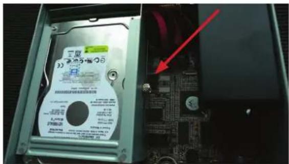
Place the top housing back and secure it with the bottom housing
natural_image
Hand pressing down on a black rectangular electronic device (no visible text or symbols)
natural_image
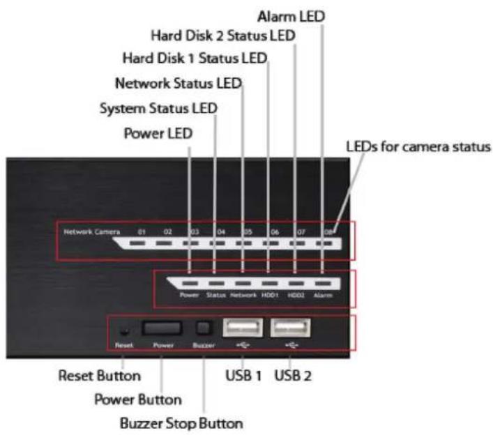
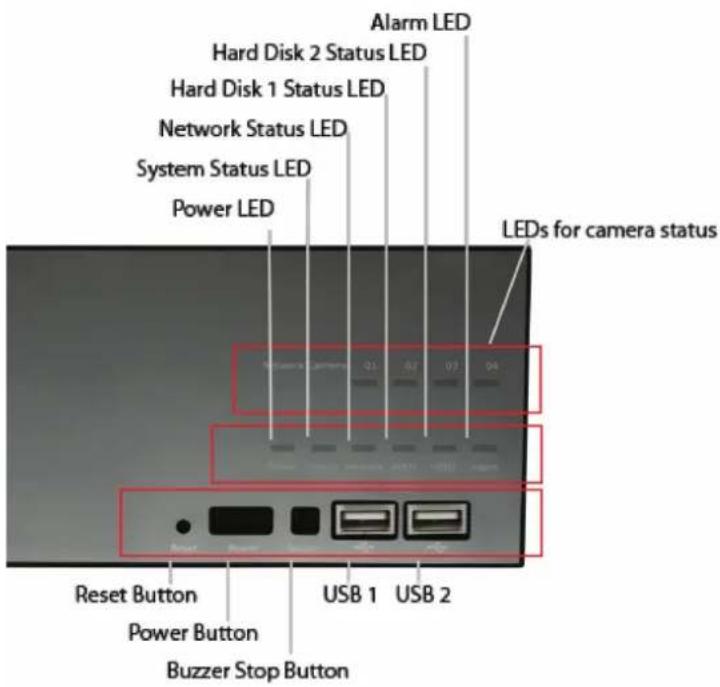
Close-up of hands interacting with a black electronic device (no visible text or symbols)System Overview (Front)
16 channel
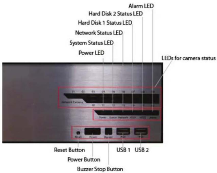
8 channel
4 channel
I/O Ports and RS-485 (Rear)

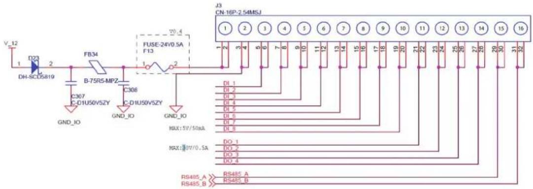
| Pin Signal | |
| 1 12V DC | |
| 2 GND | |
| 3~10 Alarm input | |
| 11 Out1 | |
| 12 Out2 | |
| 13 Out3 | |
| 14 Out4 | |
| 15 RS485+ | |
| 16 RS485- | |
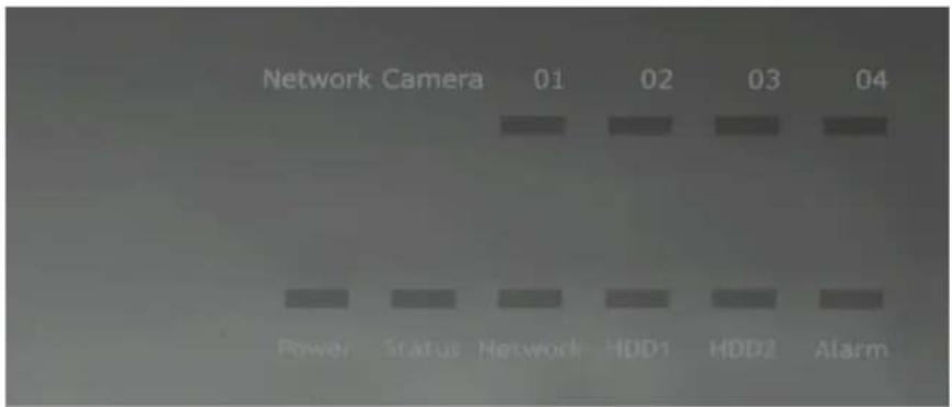
LEDs Definition
4 channel
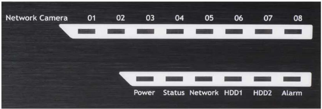
8 channel
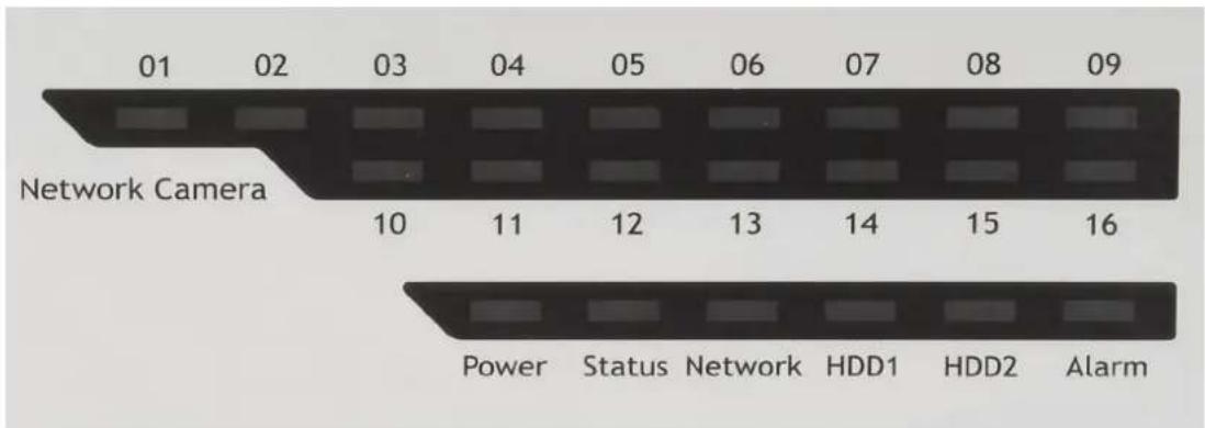
16 channel
LEDs Definition
| HDD x 2 | Green | Solid green when the hard disk is mounted and being accessed |
| Red Solid red for disk fail | ||
| Amber | Solid amber when recording is in process Blinking when recycling | |
| Network | Amber Solid amber for activity on a 1G bps network. | |
| Green | Solid green for activity on a 10/100 Mbps network. | |
| Status | Amber Blinking during firmware upgrade | |
| Green | Shows solid green for normal operation. Blinking green when firmware upgrade is done | |
| Red Flashes red for failed firmware upgrade. | ||
| Power | Green Normal operation | |
| Red System off (power adapter remains plugged in) | ||
| Amber Blinking amber indicating device is initializing | ||
| Alarm | Red Blinking when an alarm occurs | |
| None When alarm is reset | ||
| Camera LED | Green | Solid green, live connected with no event or recording activity |
| Amber | Blinking amber, manual or event recording is being performed | |
| Amber | Solid amber, schedule or continuous recording is being performed | |
| Red Recording is set but no video from camera | ||
Connect to the NVR
There are various ways you can connect to the NVR and below are the suggested methods for different network setup:
- The NVR is placed in a network with a DHCP server: Connect to the NVR by using "Smart Device Search" Utility
- The NVR is placed in a network without DHCP server (or you are connecting to it directly): Access the NVR with its default IP
Use Smart Device Search Utility
If the NVR is placed in a corporate network or a local area network where a DHCP server is already presented, run the "Smart Device Search" utility from a computer that is on the same network and locate the NVR with its IP address that is assigned by the top-level DHCP server.
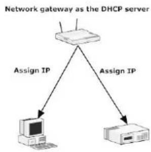
flowchart
graph TD
    A["Network gateway as the DHCP server"] -->|Assign IP| B["Computer"]
    A -->|Assign IP| C["Printer"]

flowchart
graph TD
    A["Radio"] --> B["Network"]
    B --> C["Assign IP"]
    C --> D["Computer"]
    D --> E["Network"]
    E --> F["Assign IP"]
    F --> G["Network"]
    style A fill:#f9f,stroke:#333
    style B fill:#ccf,stroke:#333
    style C fill:#cfc,stroke:#333
    style D fill:#fcc,stroke:#333
    style E fill:#cff,stroke:#333
    style F fill:#ffc,stroke:#333
    style G fill:#fcf,stroke:#333
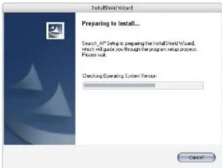
To begin, launch the "Smart Deivce Search" utility from the CD and proceed with the installation:
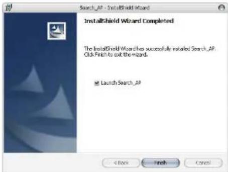
Once the installation is complete, check the "Launch the Search AP" option and click "Finish":
The search should start automatically and its status should be displayed:

The NVR should be located and its IP address should be displayed:
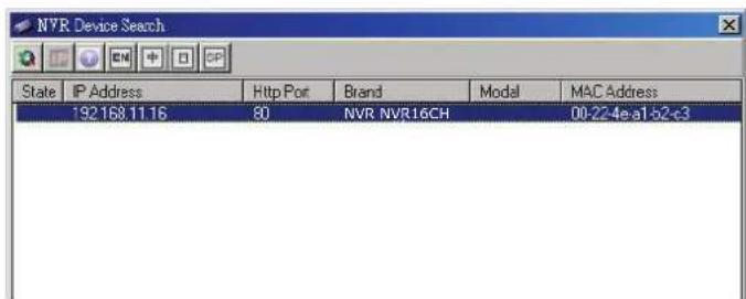
Double-click on an NVR and the search program should automatically access the NVR's web administration page from your default browser
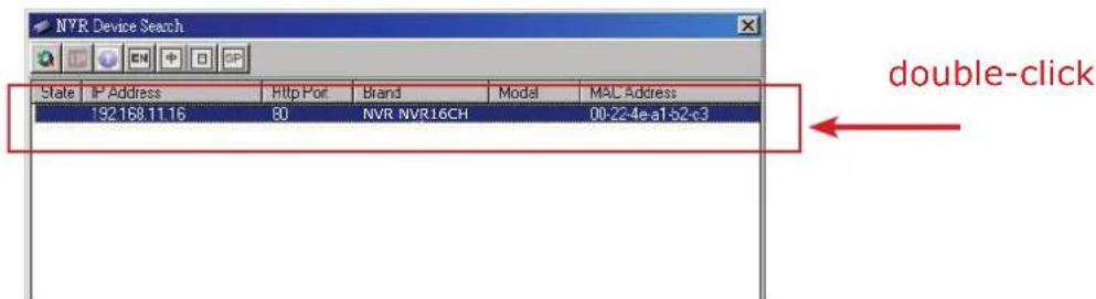
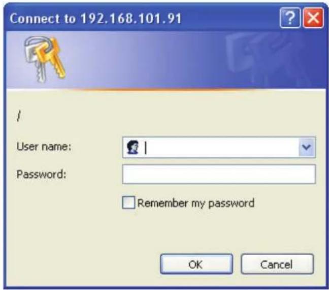
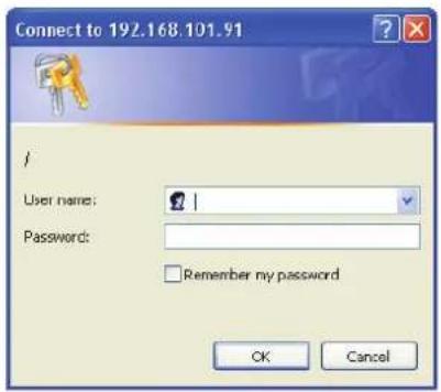
You should be prompted for the the NVR's username and password. Enter its default username "admin" and password "admin" and then click "OK" to enter the system
Access the NVR with its default IP address
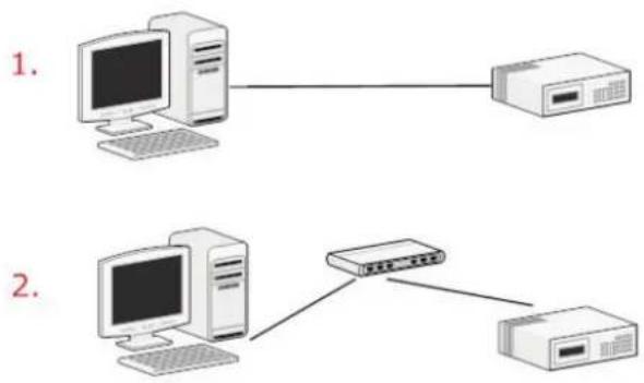
The NVR comes with a pre-configured static IP "192.168.101.50". However, it is only used when there is no DHCP server presented in the network. The NVR will turn on its DHCP server function and act as the DHCP server in the network. To connect to the NVR, use a PC that is on the same network over a switch or hub, or connect the PC directly to the NVR using a crossover CAT5 Ethernet cable.
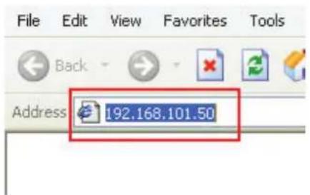
The PC that is connected directly to the NVR (or within the same local area network) should receive an IP from the NVR. Simply access the NVR from your web browser with its IP address
Again, you should be prompted for the username and password. Enter its default username "admin" and password "admin" and then click "OK" to enter the system
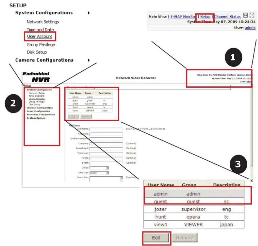
Set up Password
The default login username and password is admin/admin. To change the password of the admin account, go to "Setup" --> "System Configurations" --> "User Account", click on the "admin" account in the account list then press the "edit" button to change its password. Finally, click "Apply" to save the change.
Add a Camera
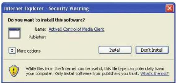
Automatic Search:
- Click the "Search" button to perform the camera search. You should be prompted to install Active Control component in order for the search to function properly. Go ahead and click "Install"
- After that, the search should begin and its status should be displayed:

- Found cameras should be listed and simply select a camera from the list and press "Configure"
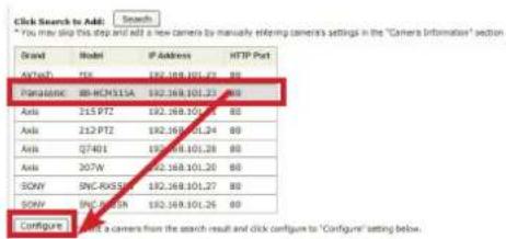
- Its corresponding information should be displayed in the "Camera Information" section. Enter its username and password and select the channel ID and name the camera.
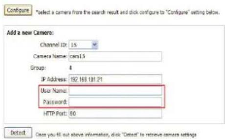
- Click on "Detect" to establish connection between the recorder and the camera. If connection establishes successfully, camera's detailed information should be polled and displayed as below

- Adjust its video format, frame rate, resolution or bitrate...etc if you wish and then click "Add" to finish adding the camera
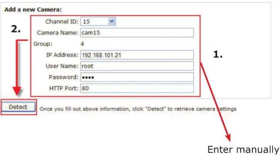
Add a camera manually
Simply follow the instruction described above but instead of using the "Search" function, enter the camera's IP address and credential in the "Camera Information" manually, then follow step 5 \~6 described above.
Recording Configurations
The “recording configurations” gives users the overall control of how and when a recording is performed and the quality of different types of recordings performed on each channels. It can help the recorder to operate with sufficient system resource by performing recording only when it’s necessary with adjustable recording frame rate.
General Settings
You can define the following in "General Settings":
• Pre-Alarm/Post-Alarm recording length
- Recording frame rate
- Enable/disable different recording types on different cameras
- Enable/disable audio recording
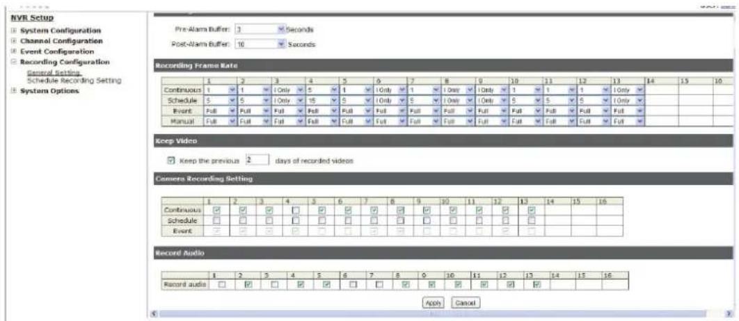
The "recording buffer" allows user to define "pre-alarm" and "post-alarm" time for event recordings. The "pre-alarm" time sets the NVR to record in advance when an event is triggered. The "post-alarm" time sets the NVR to continue recording for a period of time after an event trigger is finished.
Recording Buffer
Pre-alarm Buffer:
Post-alarm Buffer:

* The "Pre-alarm" function only works when the "Continuous" recording is also activated.
Recording frame rate allows you to set different frame rate for different types of recording instead of recording at one frame rate only. Use the drop-down menu and select one of the pre-defined frame rates for a particular recording type
Recording Frame Rate
| 1 | 2 | 3 | 4 | 5 | 6 | 7 | 8 | 9 | 10 | 11 | 12 | 13 | 14 | 15 | 16 | |
| Continuous | 1 | I Only | 1 | I Only | 1 | |||||||||||
| Schedule | 5 | I Only | 5 | I Only | 5 | |||||||||||
| Event | Full | Full | Full | Full | Full | Full | ||||||||||
| Manual | Full | Full | Full | Full | Full | Full |
The "Camera Recording Setting" section allows you to turn on or off a particular recording type on any channels.
Camera Recording Setting
| 1 | 2 | 3 | 4 | 5 | 6 | 7 | 8 | 9 | 10 | 11 | 12 | 13 | 14 | 15 | 16 | |
| Continuous | ||||||||||||||||
| Schedule | ||||||||||||||||
| Event |
The section at the bottom of the page allows you to disable audio recording (record video only) of particular channels.
Record Audio
| 1 | 2 | 3 | 4 | 5 | 6 | 7 | 8 | 9 | 10 | 11 | 12 | 13 | 14 | 15 | 16 | |
| Record audio | □ |
Schedule Recording
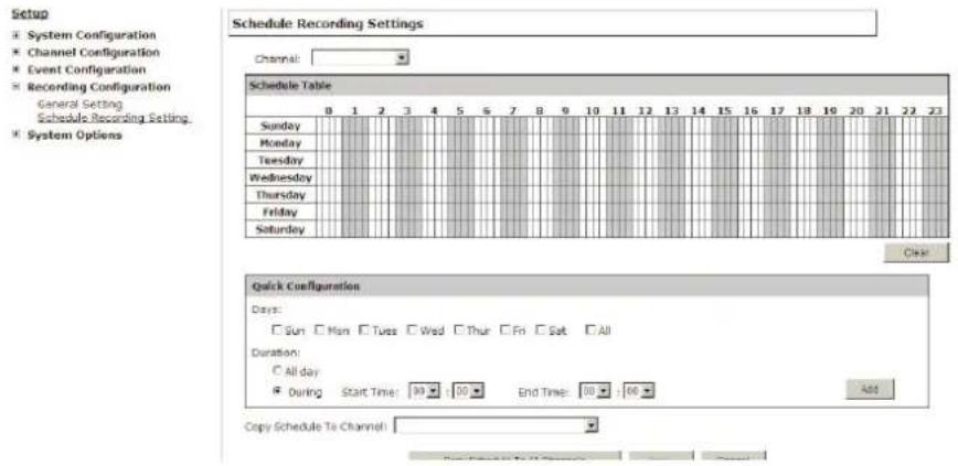
Here you can define the time range of the schedule recording for all channels.
To configure a schedule recording:
- Use the "Camera" drop-down menu and select a camera first
Camera:
- You can use the schedule table to set the time range. Click the cell boxes then move the curser horizontally lets you set what hours to perform recording during a day. Click and move vertically lets you set what days to perform recording at a specific time.
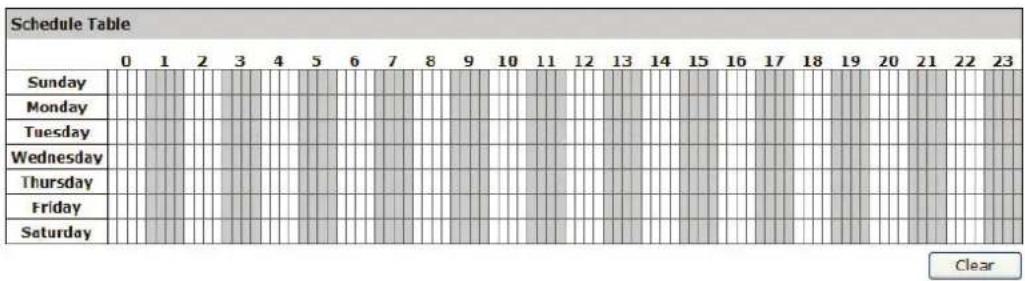
* Each cell box represents 15 minutes of time. Click one or more boxes to omit consecutive recording
- You can also use the "Quick Configuration" to define recording time range instead of clicking cell boxex one by one on the time table. Simply check what days you would like to perform recording and specify the recording duration by either choosing "All Day" or enter a start and end time for specific recording duration.
Quick Configuration
Days
Mon.
Tue.
Wed
Thur.
Fri.
Sat.
Sun.
Duration
○ All day
During
Start Time: 00:00
End Time
00:00
- Select the "Copy to" option if you would like to set the same recording schedule to another camera.

UPS Configurations
Connect the UPS to the NVR's DI/DO port for sending and receiving signals between the UPS and the NVR. Refer to the diagram below to connect the UPS with its RS-232 interface to the NVR's DI/DO port.
The NVR can receive signal from the UPS when there is a power failure and shut down itself automatically within a period of time.
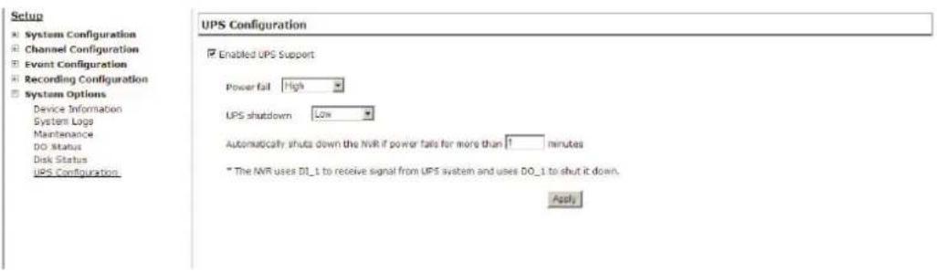
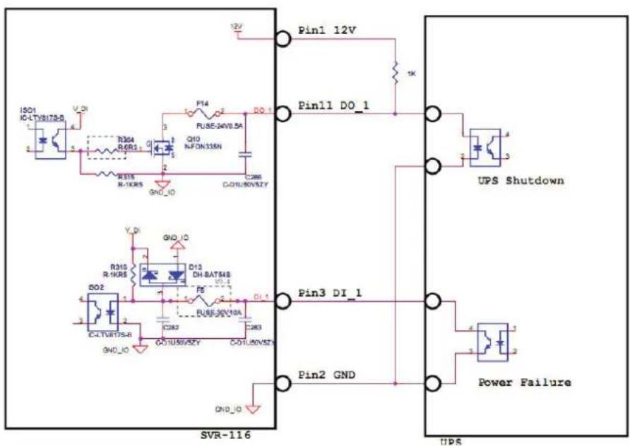
* The NVR uses DI_1 to receive signal from UPS system and uses DO_1 to shut it down.