CA-HR-PSA-EVO.002 - Uncategorized PIONEER - Free user manual and instructions
Find the device manual for free CA-HR-PSA-EVO.002 PIONEER in PDF.

User questions about CA-HR-PSA-EVO.002 PIONEER
0 question about this device. Answer the ones you know or ask your own.
Ask a new question about this device
Download the instructions for your Uncategorized in PDF format for free! Find your manual CA-HR-PSA-EVO.002 - PIONEER and take your electronic device back in hand. On this page are published all the documents necessary for the use of your device. CA-HR-PSA-EVO.002 by PIONEER.
USER MANUAL CA-HR-PSA-EVO.002 PIONEER
natural_image
Side-by-side exterior views of two red SUVs, one black and one maroon, with no visible text or symbols.EN - Installation Manual
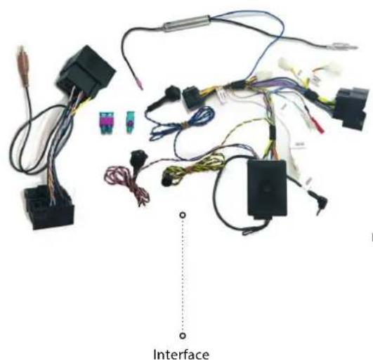
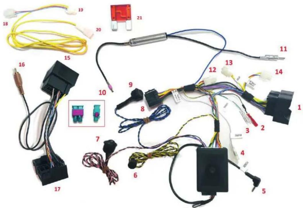
natural_image
Electrical wiring and components laid out on a white background, including connectors, wires, and a labeled 'Interface' point (no readable text or symbols beyond label)
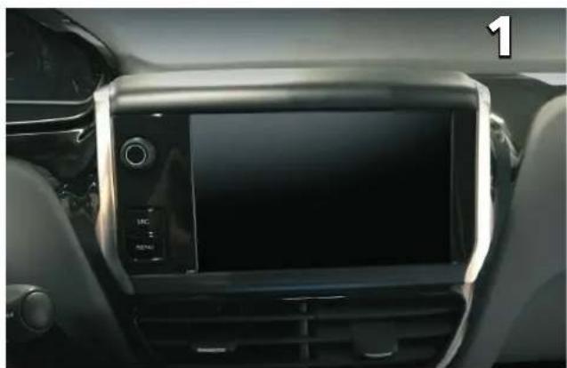
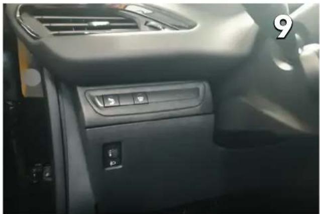
natural_image
Interior view of a car dashboard with a digital display and control panel (no visible text or symbols)Original radio system
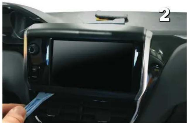
natural_image
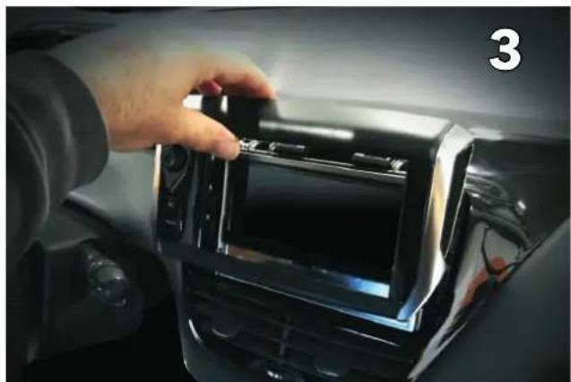
Interior view of a car dashboard with a digital display showing the front screen and a hand inserting a blue cable (no visible text or symbols)Remove front cover by lifting up as shown
natural_image
Close-up of a hand installing or adjusting a digital camera module on a car infotainment panel (no visible text or symbols)Pull upwards to remove and disconnect buttons
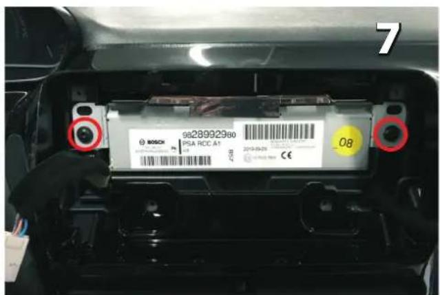
natural_image
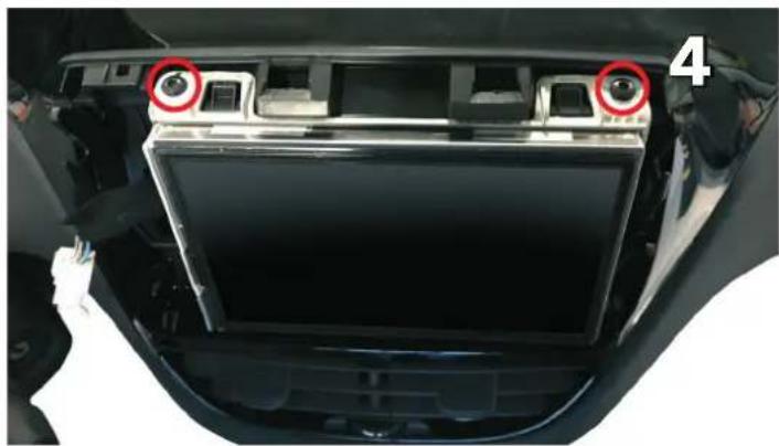
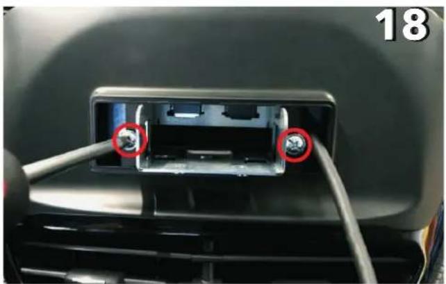
Interior view of a car showing the backrest panel and dashboard with two red circular annotations highlighting specific components (no text or symbols present)Remove two Torx screws on top
natural_image
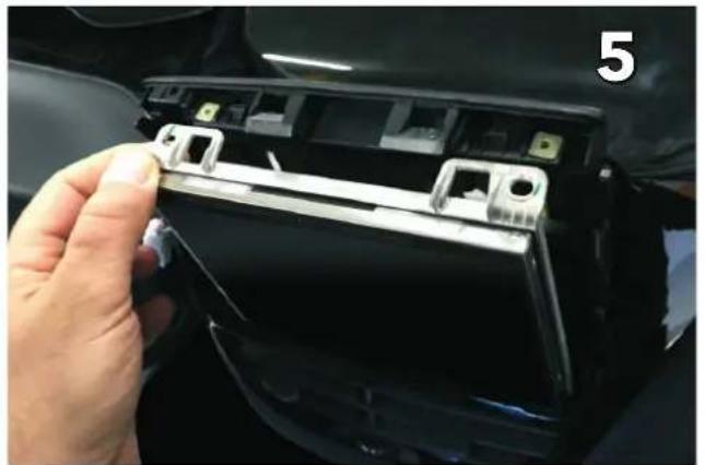
Close-up of a hand inserting a plastic component into a black car compartment, no visible text or symbolsRemove the screen by pulling it towards you
natural_image
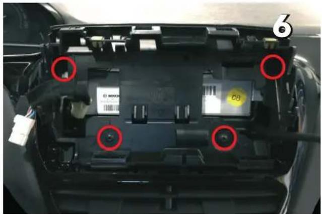
Interior view of a car showing internal components with red circles highlighting specific parts (no readable text or symbols)Remove the plastic screen holder
Remove the original stereo
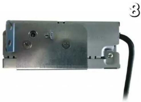
natural_image
Metal electrical component with mounting holes and a black cable, no visible text or symbolsMount the unit supports as shown by using the countersunk screws (supplied with the Pioneer product)
Install the interface (see connections next page)
- To car main connector
- To radio MUTE (yellow wire on RCA lead from Pioneer radio)
- To radio PARKING signal
(green wire on power cable from Pioneer)
- To radio REVERSE signal
(purple wire on power cable from Pioneer)
- To radio Wired Remote socket
In order to prevent ESD damage the W/R jack must be connected before any connection to the car side
-
Buzzer
-
Traction control button (ON/OFF toggle)
(necessary to drill an additional 20 mm opening)
⚠️ Disconnect the interface box for vehicles with 1-DIN radio or no radio from factory
-
To Pioneer ISO power connector
-
Tire pressure reset button (push 5 seconds to reset)
(necessary to drill an additional 20 mm opening)
⚠️ Disconnect the interface box for vehicles with 1-DIN radio or no radio from factory
- To car antenna connector
- To Pioneer FM/AM antenna input (backside of Pioneer unit
- Connect to:
- Connector 13 for open dash vehicles or 1din radio vehicles
- Connector 14 for cars with touch screen display radio
FOR FACELIFT VEHICLES
- To car main connector
- To rear view camera input
(Brown connector on RCA lead from Pioneer radio)
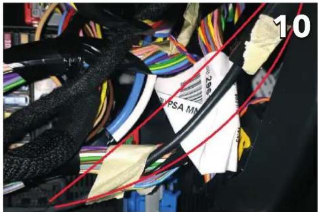
- To connector number 1
FOR FACELIFT VEHICLES
WITHOUT PERMANENT BATTERY SUPPLY BEHIND RADIO
- To be connected to number 14
- To be connected to number 12
- Accessory power supply terminal
- Fuse
Make sure connector 12 is closed before proceeding
natural_image
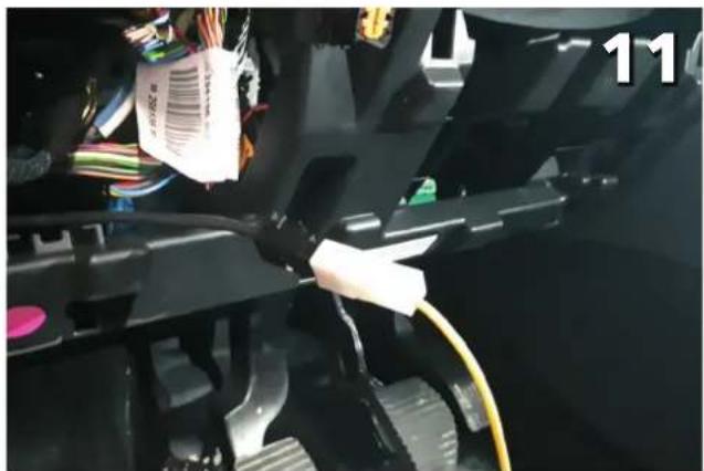
Interior view of a car dashboard with control panel and directional buttons (no visible text or symbols)Remove under dash tray Locate the accessory cable as indicated
natural_image
Close-up of a mechanical assembly with wires and connectors, no visible text or symbolsConnect number 20 onto the accessory cable
natural_image
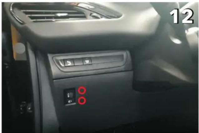
Interior view of a car dashboard with control panel and indicator lights (no visible text or symbols)Proposed locations for traction control button and tire pressure reset button
natural_image
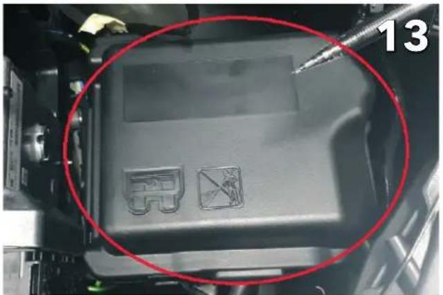
Close-up of a mechanical component with two small icons and a red circle highlighting a section (no readable text or symbols)Locate the fusebox in the engine bay and open it
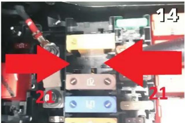
Install the supplied fuse (21) into the shown potition
natural_image
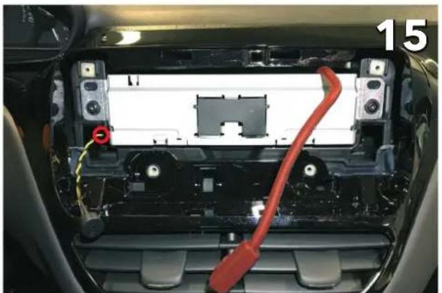
Interior view of a car showing internal components with a red cable and a red circular mark, no visible text or symbols.After all connections are made, slid ein the Pioneer unit with the display cable over the top and the buzze on the side
natural_image
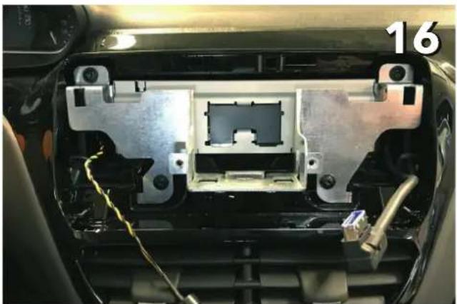
Interior view of a car showing exposed internal components with wiring and a labeled number 16 (no text or symbols on the main subject)Install the screen linkage using the original screws from the plastic holder
natural_image
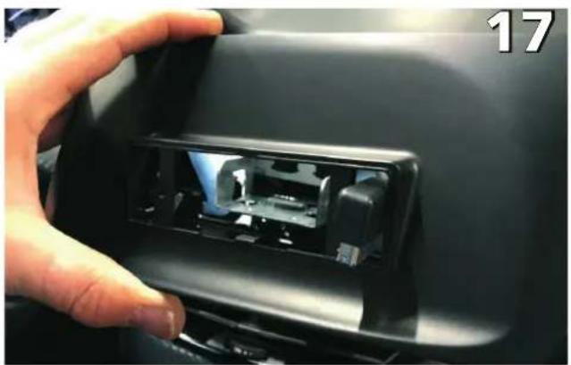
Close-up of a hand opening a car interior panel with visible internal components (no text or symbols)Install the dashboard cover (Make sure to put the display through)
natural_image
Close-up of a car's front panel showing two connected cables with red circles highlighting the cable (no text or symbols visible)Secure the dashboard cover with the supplied screws
natural_image
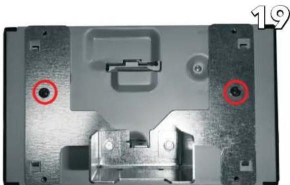
Close-up of a mechanical device casing with two red circular annotations highlighting features (no text or symbols present)Mount screen support to the screen using the two center screws on each side (included with SPH-EVO82DAB-208)
natural_image
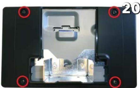
Interior view of a device casing with highlighted components and mounting holes (no text or symbols visible)Mount screen cover onto the screen support using the remaining four screws as indicated (included with SPH-EVO82DAB-208)
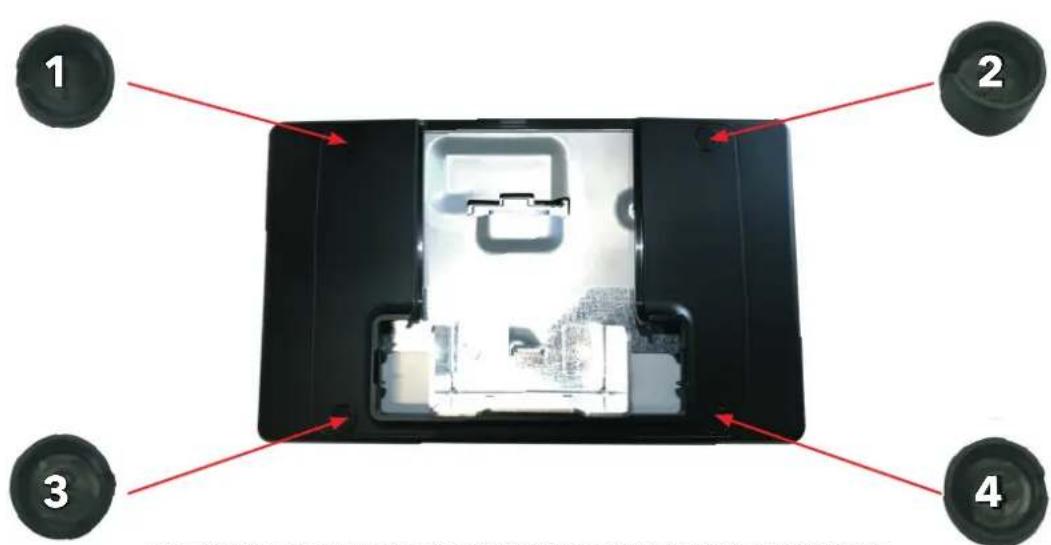
Mount screw covers, paying attention to the marked numbers and locations
21
natural_image
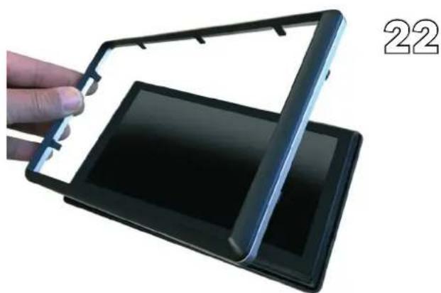
Close-up of a hand holding a black flexible electronic device with a flat panel, labeled '22' in the corner (no text on device itself)Install the front cover and chrome trim bezel on the screen Insert the connector into the screen
natural_image
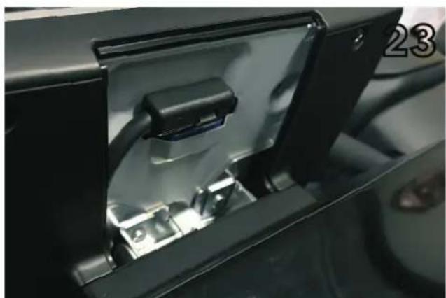
Close-up of a black electronic device with a cable inserted into a housing (no visible text or symbols)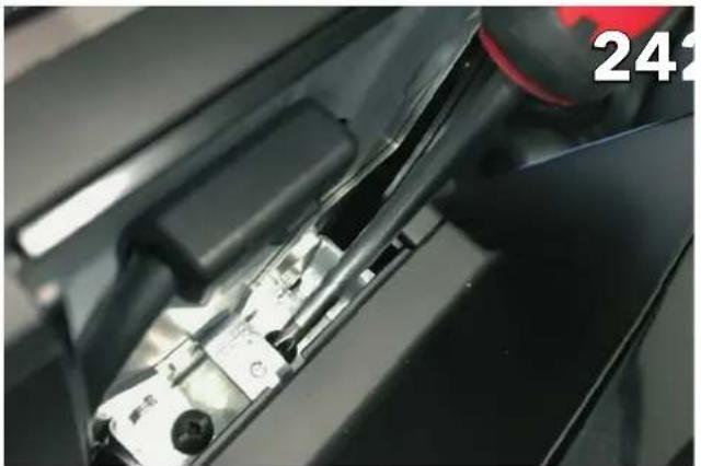
natural_image
Close-up of a mechanical component with a red cap and black handle, no visible text or symbolsSlide the screen holder into the bracket and secure with two screws (included with SPH-EVO82DAB-208)
natural_image
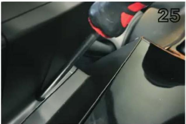
Close-up of a car's side panel showing a black handle and red grip, with the number '25' visible on the side (no readable text or symbols beyond the number)Final product image
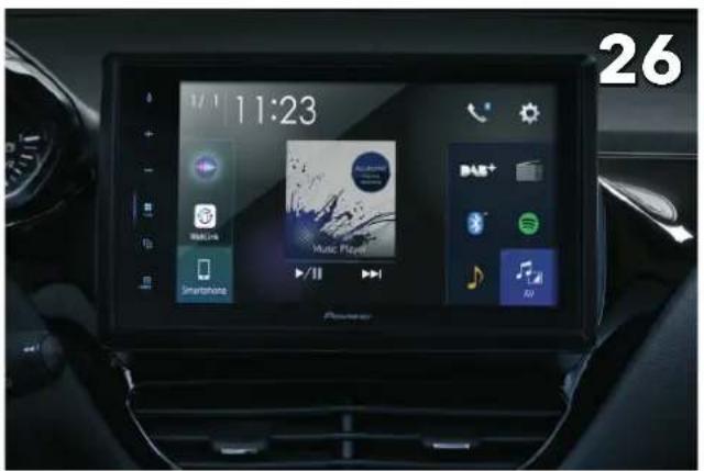
Final Product image

Scan the QR code to watch a tutorial video for the menu settings explained below
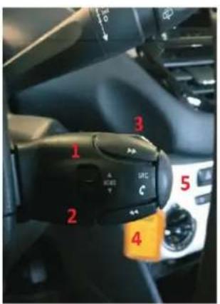
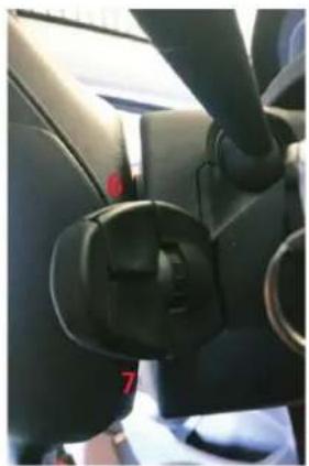
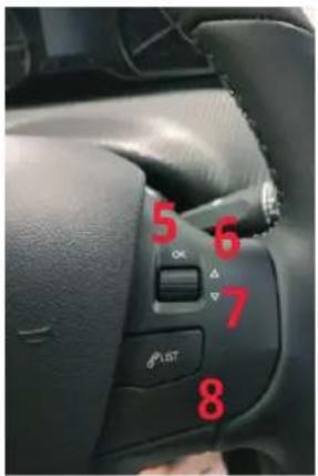
Steering Wheel Controls for SMEG / OPENDASH
natural_image
Close-up of a car's side panel showing black plastic clip and handle (no visible text or symbols)The steering wheel functions
- Track up
- Track down
- Seek up
- Seek down
- Source change
- Volume up
- Volume down
⚠️ Hold down the Source button (5), to activate the Siri function.
Steering Wheel Controls for NAC radio
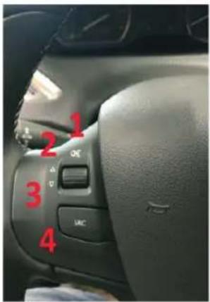
The steering wheel functions
- Mute (by pressing)
- Volume up
- Volume down
- Source change
- Seek up (by pressing)
- Preset up (by scrolling)
- Preset down (by scrolling)
- Tel. pick up / Tel. hang up
⚠️ Hold down the Source button (4), to activate the Siri function.
Menu Settings for NAC radio only
The command keys, which are used to enter, navigate and exit the menu, are:
- IGNITION key
- Tire pressure reset button
- Preset up / down rotary button
- Volume up / down rotary button
- Source button
How to enter and exit the menu
Entering the menu:
Turn on the dashboard by turning the key one step while holding down the tire pressure reset button.
The buzzer will emit four long beeps.
During this procedure, the radio will remain switched off.
Exiting the menu:
Turn off the dashboard by turning the key back.
The buzzer will emit four short beeps.
How to navigate in the menu:
As soon as the menu procedure is activated, it is possible to browse through the settings with the PRESET DOWN and PRESET UP buttons (setting list shown below). Each time the button is rotated, the buzzer will indicate the setting number by beeps. Please note that one long tone corresponds to five short ones.
It's recommended to familiarize with these functions to recognize the different type of beeps before proceeding with the settings. Different settings, which were available on the car through menus on the original radio, are kept accessible via a setup menu. The menu can heard via the buzzer and controlled with the mentioned command keys.
The retained settings are the following ones:
- Setting N° 1, FUEL CONSUMPTION/DISTANCE.
- Setting N° 2, FOLLOW-ME-HOME LIGHTING.
- Setting N° 3, WELCOME LIGHTING.
- Setting N° 4, REAR WIPER IN REVERSE.
- Setting N° 5, ACTIVE SAFETY BRAKE.
- Setting N° 6, DRL (Daytime running lights) settings.
- Setting N° 7, DIRECTIONAL HEADLIGHTS.
Each time one of the keys is pressed, the buzzer indicates the selected option:
1) Fuel consumption / distance
To choose the unit of measurement use the |<< VOLUME UP/ VOLUME DOWN>>|rotary button to scroll through the options (VOLUME DOWN to scroll down and VOLUME UP to scroll up):
- Option 1: L/Km, one short beep.
- Option 2: Km/L, two short beeps.
- Option 3: mpg, three short beeps.
To confirm the option and save it to the vehicle, press the SOURCE button: A two-tone beep indicates that the option has been saved.
To define the follow-me-home light options use the <
- Option 1: lights off, one short beep.
- Option 2: lights on for 15", two short beeps.
- Option 3: lights on for 30", three short beeps.
- Option 4: lights on for 60", four short beeps.
To confirm the option and save it to the vehicle, press the SOURCE button: A two-tone beep indicates that the option has been saved.
3) Welcome lighting
To define the welcome light options use the <
- Option 1: welcome light off, one short beep.
- Option 2: welcome light on for 15", two short beeps.
- Option 3: welcome light on for 30", three short beeps.
- Option 4: welcome light on for 60", four short beeps.
To confirm the option and save it to the vehicle, press the SOURCE button: A two-tone beep indicates that the option has been saved.
4) Rear wiper in reverse
To define the rear wiper functions use the <
- Option 1: rear wiper automatic functioning in reverse condition OFF, one short beep.
- Option 2: rear wiper automatic functioning reverse condition ON, two short beeps.
To confirm the option and save it to the vehicle, press the SOURCE button: A two-tone beep indicates that the option has been saved.
5) Active safety brake
To define the active safety brake functions use the <
- Option 1: active safety brake function OFF, one short beep.
- Option 2: active safety brake function ON, two short beeps.
To confirm the option and save it to the vehicle, press the SOURCE button: A two-tone beep indicates that the option has been saved.
6) DRL (Daytime Running Lights)
To define the DRL functions use the <
- Option 1: DRL function OFF, one short beep.
- Option 2: DRL function ON, two short beeps.
To confirm the option and save it to the vehicle, press the SOURCE button: A two-tone beep indicates that the option has been saved.
7) Directional headlights
To define the directional light functions use the <
- Option 1: directional light function OFF, one short beep.
- Option 2: directional light function ON, two short beeps.
To confirm the option and save it to the vehicle, press the SOURCE button: A two-tone beep indicates that the option has been saved.