VigorSwitch P1085 - Network switch Draytek - Free user manual and instructions
Find the device manual for free VigorSwitch P1085 Draytek in PDF.

| Product Type | Managed Gigabit PoE+ Switch |
| Brand | Draytek |
| Model | VigorSwitch P1085 |
| Ports | 8 x 10/100/1000 Mbps PoE+ (802.3at/af), 2 x SFP (100/1000M) |
| PoE Budget | 85W total (up to 30W per port) |
| Switching Capacity | 20 Gbps |
| MAC Address Table | 8K entries |
| VLAN Support | 802.1Q VLAN (up to 256 groups) |
| Management | Web GUI, CLI, SNMP v1/v2c/v3, RMON |
| Power Supply | Internal AC 100-240V, 50-60Hz |
| Dimensions (W x D x H) | 280 x 180 x 44 mm (1U rackmountable) |
| Weight | 2.1 kg |
| Operating Temperature | 0°C to 40°C |
| Humidity | 10% to 90% non-condensing |
| Features | IGMP snooping, QoS, link aggregation, port mirroring, loop protection, storm control |
Frequently Asked Questions - VigorSwitch P1085 Draytek
User questions about VigorSwitch P1085 Draytek
0 question about this device. Answer the ones you know or ask your own.
Ask a new question about this device
Download the instructions for your Network switch in PDF format for free! Find your manual VigorSwitch P1085 - Draytek and take your electronic device back in hand. On this page are published all the documents necessary for the use of your device. VigorSwitch P1085 by Draytek.
USER MANUAL VigorSwitch P1085 Draytek
natural_image
Exterior view of a black network switch device with visible ports and ventilation grille (no readable text or symbols beyond branding)Your reliable networking solutions partner
User's Guide
VigorSwitch P1085
PoE Web Smart Gigabit Switch
User's Guide
Version: 1.0
Firmware Version: V2.5.1
(For future update, please visit DrayTek web site)
Date: December 25, 2019
Copyrights
© All rights reserved. This publication contains information that is protected by copyright. No part may be reproduced, transmitted, transcribed, stored in a retrieval system, or translated into any language without written permission from the copyright holders.
Trademarks
The following trademarks are used in this document:
● Microsoft is a registered trademark of Microsoft Corp.
● Windows, Windows 95, 98, Me, NT, 2000, XP, Vista, 7, 8, 10 and Explorer are trademarks of Microsoft Corp.
● Apple and Mac OS are registered trademarks of Apple Inc.
● Other products may be trademarks or registered trademarks of their respective manufacturers.
Caution
Circuit devices are sensitive to static electricity, which can damage their delicate electronics. Dry weather conditions or walking across a carpeted floor may cause you to acquire a static electrical charge.
To protect your device, always:
- Touch the metal chassis of your computer to ground the static electrical charge before you pick up the circuit device.
- Pick up the device by holding it on the left and right edges only.
Warranty
We warrant to the original end user (purchaser) that the device will be free from any defects in workmanship or materials for a period of one (1) year from the date of purchase from the dealer. Please keep your purchase receipt in a safe place as it serves as proof of date of purchase. During the warranty period, and upon proof of purchase, should the product have indications of failure due to faulty workmanship and/or materials, we will, at our discretion, repair or replace the defective products or components, without charge for either parts or labor, to whatever extent we deem necessary tore-store the product to proper operating condition. Any replacement will consist of a new or re-manufactured functionally equivalent product of equal value, and will be offered solely at our discretion. This warranty will not apply if the product is modified, misused, tampered with, damaged by an act of God, or subjected to abnormal working conditions. The warranty does not cover the bundled or licensed software of other vendors. Defects which do not significantly affect the usability of the product will not be covered by the warranty. We reserve the right to revise the manual and online documentation and to make changes from time to time in the contents hereof without obligation to notify any person of such revision or changes.
Be a Registered Owner
Web registration is preferred. You can register your Vigor router via http://www.DrayTek.com.
Firmware & Tools Updates
Due to the continuous evolution of DrayTek technology, all routers will be regularly upgraded. Please consult the DrayTek web site for more information on newest firmware, tools and documents.
More update, please visit www.draytek.com.
Table of Contents
Part I Introduction....1
I-1 Introduction ...... 2
I-1-1 Key Features 2
I-1-2 Specifications 3
I-1-3 Packing List 4
I-1-4 LED Indicators and Connectors .... 4
I-2 Installation....6
I-2-1 Typical Applications....6
I-2-2 Installing Network Cables 8
I-2-3 Configuring the Management Agent of Switch....8
I-2-4 Managing VigorSwitch P1085 through Ethernet Port 8
I-2-5 IP Address Assignment 9
I-3 Accessing Web Page of VigorSwitch 13
I-4 Dashboard.... 14
I-5 Status 15
I-5-1 Port Bandwidth Utilization 15
I-5-2 LLDP Statistics 15
Part II Switch LAN....17
II-1 General Setup.... 18
II-1-1 Management IP/VLAN.... 18
II-2 Port Setting 20
II-2-1 General Setting.... 20
II-2-2 Protected Ports.... 22
II-3 Mirror 23
II-4 Link Aggregation 24
II-4-1 LAG Setting 24
II-4-2 LAG Management 25
II-4-3 LAG Port Setting.... 26
II-4-4 LACP Setting 27
II-4-5 LACP Port Setting 28
II-5 VLAN Management....29
II-5-1 Create VLAN 29
II-5-2 Interface Settings.... 30
II-5-3 Voice VLAN 32
II-5-3-1 Properties 32
II-5-3-2 Telephony OUI Setting 33
II-5-3-3 Port Setting.... 34
II-5-4 MAC VLAN 35
II-5-4-1 MAC Group 35
I-5-4-3 Group Binding 36
II-5-5 Surveillance VLAN.... 37
II-5-5-1 Property 37
II-5-6-1 Surveillance OUI....39
II-6 EEE 40
II-7 Multicast 41
II-7-1 Properties 41
II-7-2 IGMP Snooping 42
II-7-2-1 IGMP Setting 42
II-7-2-2 IGMP Querier Setting....44
II-7-2-3 IGMP Static Group 45
II-7-2-4 IGMP Group Table....46
II-7-2-5 IGMP Router Table....47
II-8 Jumbo Frame 48
II-9 STP 49
II-9-1 Properties 49
II-9-2 Port Setting....50
II-9-3 Bridge Setting 52
II-9-4 Port Advanced Setting....53
II-9-5 Statistics 54
II-10 MAC Address Table....55
II-10-1 Static MAC Setting 55
II-10-2 Dynamic Address Setting 56
II-10-3 Dynamic Learned 56
II-11 Blocked Port Recover....58
Part III ONVIF Surveillance....59
III-1 Topology....60
III-1-1 Status 60
III-2-2 Throughput Threshold 65
III-2 Video 67
III-3 Device Maintenance 68
III-3-1 General....68
III-3-2 Network 70
III-3-3 Security....72
Part IV Security 73
IV-1 Storm Control....74
IV-1-1 Properties....74
IV-1-2 Port Setting 75
IV-2 DoS 76
IV-2-1 Properties....76
IV-2-2 DoS Port Setting 78
IV-3 IP Source Guard 79
IV-3-1 Port Settings....79
IV-3-2 IMPV Binding 80
IV-4 IP Conflict Prevention 81
IV-5 Loop Protection....85
Part V ACL Configuration....87
V-1 Create ACL 88
V-1-1 MAC 88
V-1-2 IPv4 88
V-1-3 IPv6 89
V-2 Create ACE 91
V-2-1 MAC 91
V-2-2 IPv4 92
V-2-3 IPv6 94
V-3 ACL Binding 96
Part VI QoS Configuration....97
VI-1 General 98
VI-1-1 Properties 98
VI-1-1-1 QoS General Setting 98
VI-1-1-2 Trust Ports 99
VI-1-2 Port Settings.... 100
VI-1-3 Queue Settings 101
VI-1-4 CoS Mapping 102
VI-2-2 Egress Shaping Rate 106
VI-2-3 Egress Shaping Per Queue 107
Part VII PoE Configuration....109
VII-1 Properties 110
VII-2 Status....111
VII-3 Schedule....112
VII-3-1 Schedule Profile.... 112
VII-3-2 Port Scheduling.... 113
Part VIII System Maintenance....115
VIII-1 TR-069....116
VIII-2 OpenVPN....118
VIII-3 Webhook....119
VIII-4 LLDP 120
VIII-4-1 Properties.... 120
VIII-4-2 LLDP Port Setting 121
VIII-4-3 LLDP Local Device....123
VIII-4-4 LLDP Remote Device 124
VIII-4-7 LLDP Overloading.... 125
VIII-5 SNMP 126
VIII-5-1 View 127
VIII-5-2 Group 128
VIII-5-3 Community 129
VIII-5-4 User....130
VIII-5-5 Engine ID 132
VIII-5-5-1 Local Engine ID.... 132
VIII-5-5-2 Remote Engine ID 133
VIII-5-6 Trap Event.... 134
VIII-5-7 Notification 135
VIII-6 Access Manager 137
VIII-7 Time and Date 138
VIII-7-1 System Time Zone 138
VIII-7-2 Time 139
VIII-8 Backup Manager.... 140
VIII-9 Upgrade Manager....141
VIII-10 Account Manager.... 142
VIII-11 Factory Default.... 144
VIII-12 Reboot Switch.... 145
Part IX Diagnostics....147
IX-1 Device Check.... 148
IX-2 Cable Diagnostics.... 149
IX-3 Ping Test....150
IX-4 SysLog....151
IX-4-1 SysLog Explorer.... 151
IX-4-2 SysLog Settings 152
IX-4-2-1 SysLog Service 152
IX-4-2-2 Local SysLog.... 153
IX-4-2-3 Remote SysLog 154
IX-4-2-4 SysLog Mail 155
Part X Mail Alert 157
X-1 Alert Setting 158
Part XI Telnet Commands....161
XI-1 Accessing Telnet of VigorSwitch.... 162
XI-2 Available Commands.... 164
XI-2-1 Clear Configuration 164
XI-2-2 Clock Configuration.... 170
XI-2-3 Configure Configuration 171
XI-2-4 Copy Configuration 241
XI-2-5 Delete Configuration 242
XI-2-6 Disable Configuration.... 242
XI-2-7 End Configuration 243
XI-2-8 Exit Configuration.... 243
XI-2-9 Hardware-Monitor Configuration.... 244
XI-2-10 Ping Configuration.... 244
XI-2-11 Reboot Configuration 245
XI-2-12 Restore-defaults Configuration 245
XI-2-13 Save Configuration.... 245
XI-2-14 Show Configuration.... 246
XI-2-15 SSL Configuration.... 247
XI-2-16 Terminal Configuration.... 247
XI-2-17 Traceroute Configuration 248
Appendix: Reference....249
A-1 What's the Ethernet 249
A-2 Media Access Control (MAC) 252
A-3 Flow Control.... 256
Index 259
Part I Introduction
I-1 Introduction
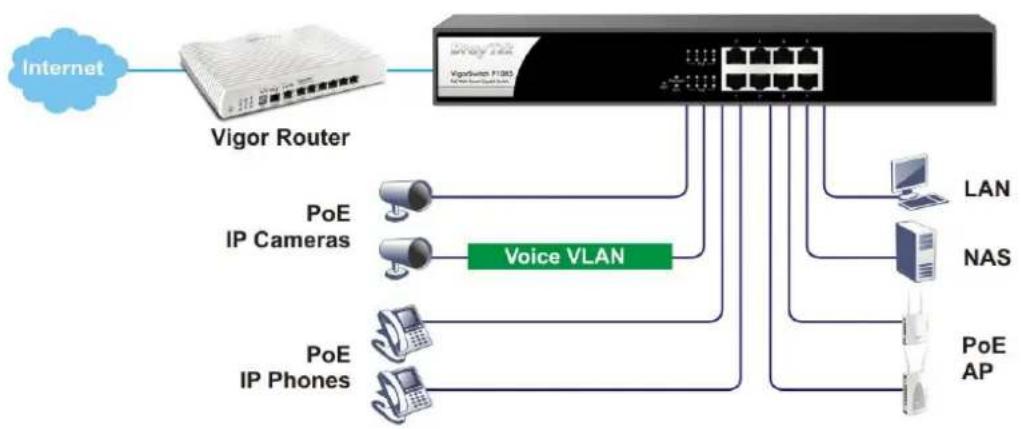
VigorSwitch P1085, PoE Web Smart Gigabit, is a standard switch that meets all IEEE 802.3/ u/ x/ z Gigabit, Fast Ethernet specifications. The switch has 8 10/ 100/ 1000Mbps TP ports. It supports telnet, http, https, SSH and SNMP interface for switch management.
The network administrator can login the switch to monitor, configure and control each port's activity. In addition, the switch implements the QoS (Quality of Service), VLAN, and Trunking. It is suitable for office application.
VigorSwitch supports IEEE 802.3az, Energy-Efficient Ethernet, and provides power saving feature. It can efficiently save the switch power with auto detect the client idle and cable length to provide different power.
flowchart
graph LR
    A["Internet"] --> B["Vigor Router"]
    B --> C["Voic VLAN"]
    C --> D["PoE IP Cameras"]
    C --> E["PoE IP Phones"]
    C --> F["LAN"]
    C --> G["NAS"]
    C --> H["PoE AP"]
I-1-1 Key Features
Below shows key features of this device:
QoS
The switch offers powerful QoS function. This function supports 802.1p VLAN tag priority and DSCP on Layer 3 of network framework.
VLAN
Support Port-based VLAN and IEEE802.1Q Tag VLAN. Support 24 active VLANs and VLAN ID 1\~4094.
Port Trunking
Allows one or more links to be aggregated together to form a Link Aggregation Group by the static setting.
Power Saving
The Power saving using the IEEE 802.3az, Energy-Efficient Ethernet to detect the client idle and cable length automatically and provides the different power. It could efficient to save the switch power and reduce the power consumption.
I-1-2 Specifications
The VigorSwitch P1085, a standalone off-the-shelf switch, provides the comprehensive features listed below for users to perform system network administration and efficiently and securely serve your network.
Hardware
8 10/100/1000Mbps Auto-negotiation Gigabit Ethernet TP ports with PoE+
❖ Jumbo frame support 9KB
◆ Programmable classifier for QoS (Layer 2/ Layer 3)
✿ 8K MAC address and support VLAN ID(1\~4094)
- Per-port shaping, policing, and Broadcast Storm Control
Power Saving with IEEE 802.3az, Energy-Efficient Ethernet
Full-duplex flow control (IEEE802.3x) and half-duplex backpressure
◆ Extensive front-panel diagnostic LEDs; Power, System, PoE fail and PoE/link activity
Hardware reset button for resetting configuration to factory default by pressing over 5 seconds
Management
◆ Supports per port traffic monitoring counters
◆ Supports a snapshot of the system Information when you login
◆ Supports port mirror function
◆ Supports the static trunk function
◆ Supports 802.1Q VLAN
◆ Supports user management and limits three users to login
Maximal packet length can be up to 9600 bytes for jumbo frame application
◆ Supports Broadcasting Suppression to avoid network suspended or crashed
◆ Supports to send the trap event while monitored events happened
✿ Supports default configuration which can be restored to overwrite the current configuration which is working on via Web UI and Reset button of the switch
◆ Supports on-line plug/ unplug SFP modules
✿ Supports Quality of Service (QoS) for real time applications based on the information taken from Layer 2 to Layer 3
Built-in web-based management and CLI management, providing a more convenient UI for the user
I-1-3 Packing List
Before you start installing the switch, verify that the package contains the following:
VigorSwitch P1085
AC Power Cord
◆ Quick Start Guide
Rubber feet
Rack mount kit
Please notify your sales representative immediately if any of the aforementioned items is missing or damaged.
I-1-4 LED Indicators and Connectors
Before you use the Vigor device, please get acquainted with the LED indicators and connectors first. There are 8 Ethernet ports and SFP ports on the front panel of the switch. LED display area, locating on the front panel, contains an ACT, Power LED and ports working status of the switch.
LED Explanation

text_image
PoE for Port 1 to Port 8 VigorSwitch P1085 PoE Web Smart Gigabit Switch RST FvE FvE/Mort 3.5 FvE FvE RJ45 LNK/ ACT Port 1 to Port 8| LED | Color | Explanation |
| PoE/ Alert (for P1085) | On Devices connected over the PoE maximum power budget. | |
| Blinking More than 80% of maximum power budget is supplied for PoE device(s). | ||
| Off Devices connected within the PoE maximum power budget. | ||
| SYS | On | The switch finishes system booting and the system is ready. |
| Blinking The switch is powered on and starts system booting. | ||
| Off | The power is off or the system is not ready / malfunctioning. | |
| PWR | On The device is powered on. | |
| Off The device is powered off. | ||
| On The port is supplied with PoE power. | ||
PoE 1\~8
| Off No PoE power is supplied on the port. | ||
| Interface | Description | |
| RST | Factory reset button.Press it to reboot the system. (<5 seconds) The PoE/ Alert and SYS LEDs will blink too.Press it to reset the system with factory default settings. (5~20 seconds)The PoE/ Alert and SYS LEDs will be off if RST button is pressed between 5 seconds and 10 seconds. | |
| Port 1 ~ 44 (RJ45) Port 1 to Port 44 can be used for Ethernet connection and PoE connection, depending on the device connected. | ||
| RJ 45 LNK/ ACT Port 1 ~ 8 | Port 1 to Port 8 can be used for Ethernet connection and PoE connection, depending on the device connected. | |
| PoE for Port 1 ~ 8 | ||
 | Power inlet for AC input (100~240V/ AC, 50/ 60Hz). | |
Note:
Power Output -
- IEEE 802.3af Max. 15.4W Output Supported
- IEEE 802.3at Max. 30W Output Supported
PoE Power Budget--
● 140 Watts (Max)
I-2 Installation
I-2-1 Typical Applications
The VigorSwitch implements 8 Gigabit Ethernet TP ports with auto MDIX and four slots for the removable module supporting comprehensive fiber types of connection, including LC and BiDi-LC SFP modules. The switch is suitable for the following applications:
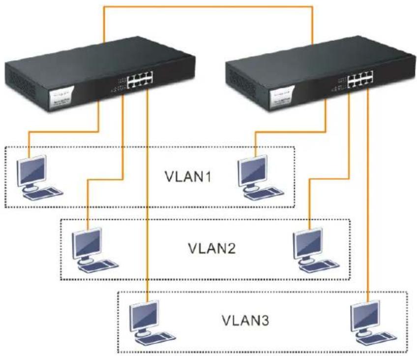
Case 1: All switch ports are in the same local area network.
Every port can access each other. (*The switch image is sample only.)

flowchart
graph TD
    A["Switch 1"] --> B["Computer Port"]
    C["Switch 2"] --> D["Computer Port"]
    B --> E["Ethernet Port"]
    D --> F["Ethernet Port"]
    style A fill:#000,stroke:#fff,color:#fff
    style C fill:#000,stroke:#fff,color:#fff
    style B fill:#000,stroke:#fff,color:#fff
    style D fill:#000,stroke:#fff,color:#fff
    style E fill:#000,stroke:#fff,color:#fff
    style F fill:#000,stroke:#fff,color:#fff
If VLAN is enabled and configured, each node in the network that can communicate each other directly is bounded in the same VLAN area.
Case 2: The same VLAN members can be at different switches with the same VID
flowchart
graph TD
    A["Switch 1"] --> B["Computer"]
    C["Switch 2"] --> D["Computer"]
    E["Switch 3"] --> F["Computer"]
    B --> G["VLAN1"]
    D --> H["VLAN2"]
    F --> I["VLAN3"]
Case 3: Desktop Installation
- Install the switch on a level surface that can support the weight of the unit and the relevant components.
- Plug the switch with the female end of the provided power cord and plug the male end to the power outlet.
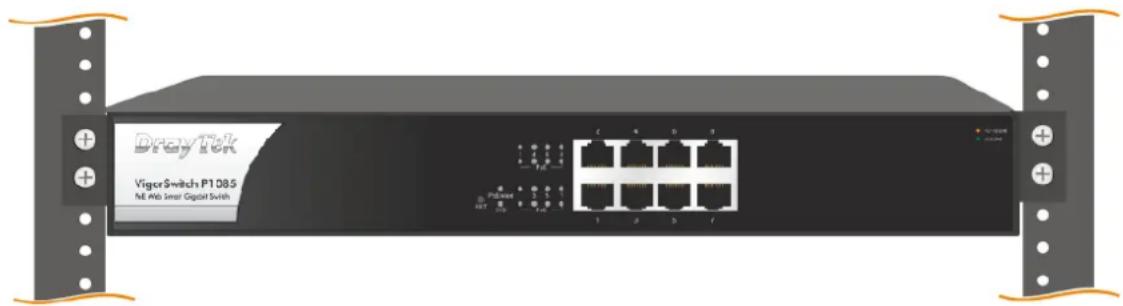
Case 4: Rack-mount Installation
The switch may be standalone, or mounted in a rack. Rack mounting facilitate to an orderly installation when you are going to install series of networking devices.
Procedures to Rack-mount the switch:
- Disconnect all the cables from the switch before continuing.
- Place the unit the right way up on a hard, flat surface with the front facing you.
- Locate a mounting bracket over the mounting holes on one side of the unit.
- Insert the screws and fully tighten with a suitable screwdriver.
- Repeat the two previous steps for the other side of the unit.
- Insert the unit into the rack and secure with suitable screws.
- Reconnect all the cables.
text_image
VigoSwitch P1085 NE Hub Smart Capital SwitchI-2-2 Installing Network Cables
Crossover or straight-through cable: All the ports on the switch support Auto-MDI/ MDI-X functionality. Both straight-through or crossover cables can be used as the media to connect the switch with PCs as well as other devices like switches, hubs or router.
Category 3, 4, 5 or 5e, 6 UTP/STP cable: To make a valid connection and obtain the optimal performance, an appropriate cable that corresponds to different transmitting/receiving speed is required. To choose a suitable cable, please refer to the following table.
| Media | Speed | Wiring |
| 10/100/1000 Mbps copper | 10 Mbps Category 3,4,5 UTP/ STP | |
| 100Mbps Category 5 UTP/ STP | ||
| 1000 Mbps Category 5e, 6 UTP/ STP | ||
I-2-3 Configuring the Management Agent of Switch
Users can monitor and configure the switch through the following procedures.
Configuring the Management Agent of VigorSwitch P1085 through the Ethernet Port.
There are several ways to configure and monitor the switch through Ethernet port, includes Web-UI and SNMP.
VigorSwitch, for example:
IP Address: 192.168.1.224
Subnet Mask: 255.255.255.0
Default Gateway: 192.168.1.254

text_image
VigorSwitch P1085 PeE Wls: Stream OgasJet Switch Assign a reasonable IP Address, for example: IP Address: 192.168.1.100 Subnet Mask: 255.255.255.0 Default Gateway: 192.168.1.254 Ethernet LANI-2-4 Managing VigorSwitch P1085 through Ethernet Port
Before start using the switch, the IP address setting of the switch should be done, then perform the following steps:
- Set up a physical path between the configured the switch and a PC by a qualified UTP Cat. 5e cable with RJ-45 connector.
Note: If PC directly connects to the switch, you have to setup the same subnet mask between them. But, subnet mask may be different for the PC in the remote site. Please refer to the above figure about the Web Smart Switch default IP address information.
- After configuring correct IP address on your PC, open your web browser and access switch's IP address.
Default system account is "admin", with password "admin" in default. Switch IP address is "192.168.1.224" by default with DHCP client enabled.
I-2-5 IP Address Assignment
For IP address configuration, there are three parameters needed to be filled in. They are IP address, Subnet Mask, Default Gateway and DNS.
IP address:
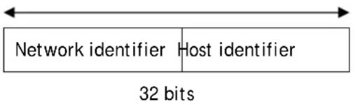
The address of the network device in the network is used for internetworking communication. Its address structure looks is shown below. It is “classful” because it is split into predefined address classes or categories.
Each class has its own network range between the network identifier and host identifier in the 32 bits address. Each IP address comprises two parts: network identifier (address) and host identifier (address). The former indicates the network where the addressed host resides, and the latter indicates the individual host in the network which the address of host refers to. And the host identifier must be unique in the same LAN. Here the term of IP address we used is version 4, known as IPv4.
text_image
Network identifier Host identifier 32 bitsWith the classful addressing, it divides IP address into three classes, class A, class B and class C. The rest of IP addresses are for multicast and broadcast. The bit length of the network prefix is the same as that of the subnet mask and is denoted as IP address/ X, for example, 192.168.1.0/ 24. Each class has its address range described below.
Class A:
Address is less than 126.255.255.255. There are a total of 126 networks can be defined because the address 0.0.0.0 is reserved for default route and 127.0.0.0/8 is reserved for loopback function.
text_image
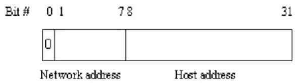
Bit # 0 1 78 31 0 Network address Host addressClass B:
IP address range between 128.0.0.0 and 191.255.255.255. Each class B network has a 16-bit network prefix followed 16-bit host address. There are 16,384 (2^14)/ 16 networks able to be defined with a maximum of 65534 (2^16 -2) hosts per network.
text_image
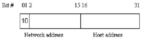
Bit # 01 2 15 16 31 10 Network address Host addressClass C:
IP address range between 192.0.0.0 and 223.255.255.255. Each class C network has a 24-bit network prefix followed 8-bit host address. There are 2,097,152 (2^21)/24 networks able to be defined with a maximum of 254 (2^8 -2) hosts per network.

text_image
Bit # 0 1 2 3 23 24 31 110 Network address Host addressClass D and E:
Class D is a class with first 4 MSB (Most significance bit) set to 1-1-1-0 and is used for IP Multicast. See also RFC 1112. Class E is a class with first 4 MSB set to 1-1-1-1 and is used for IP broadcast.
According to IANA (Internet Assigned Numbers Authority), there are three specific IP address blocks reserved and able to be used for extending internal network. We call it Private IP address and list below:
| Class A 10.0.0.0 --- | 10.255.255.255 |
| Class B 172.16.0.0 --- | 172.31.255.255 |
| Class C 192.168.0.0 --- | 192.168.255.255 |
Please refer to RFC 1597 and RFC 1466 for more information.
Subnet mask:
It means the sub-division of a class-based network or a CIDR block. The subnet is used to determine how to split an IP address to the network prefix and the host address in bitwise basis. It is designed to utilize IP address more efficiently and ease to manage IP network.
For a class B network, 128.1.2.3, it may have a subnet mask 255.255.0.0 in default, in which the first two bytes is with all 1s. This means more than 60 thousands of nodes in flat IP address will be at the same network. It's too large to manage practically. Now if we divide it into smaller network by extending network prefix from 16 bits to, say 24 bits, that's using its third byte to subnet this class B network. Now it has a subnet mask 255.255.255.0, in which each bit of the first three bytes is 1. It's now clear that the first two bytes is used to identify the class B network, the third byte is used to identify the subnet within this class B network and, of course, the last byte is the host number.
Not all IP address is available in the sub-netted network. Two special addresses are reserved. They are the addresses with all zero's and all one's host number. For example, an IP address 128.1.2.128, what IP address reserved will be looked like? All 0s mean the network itself, and all 1s mean IP broadcast.
128.1.2.128/25
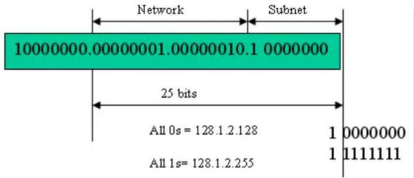
text_image
Network Subnet 10000000.00000001.00000010.1 0000000 25 bits All 0s = 128.1.2.128 All 1s = 128.1.2.255 1 0000000 1 1111111In this diagram, you can see the subnet mask with 25-bit long, 255.255.255.128, contains 126 members in the sub-netted network. Another is that the length of network prefix equals the number of the bit with 1s in that subnet mask. With this, you can easily count the number of IP addresses matched. The following table shows the result.
Prefix Length No. of IP matched No. of Addressable IP
| /32 | 1 | - | |
| /31 | 2 | - | |
| /30 | 4 | 2 | |
| /29 | 8 | 6 | |
| /28 | 16 | 14 | |
| /27 | 32 | 30 | |
| /26 | 64 | 62 | |
| /25 | 128 | 126 | |
| /24 | 256 | 254 | |
| /23 | 512 | 510 | |
| /22 | 1024 | 1022 | |
| /21 | 2048 | 2046 | |
| /20 | 4096 | 4094 | |
| /19 | 8192 | 8190 | |
| /18 | 16384 | 16382 | |
| /17 | 32768 | 32766 | |
| /16 | 65536 | 65534 |
According to the scheme above, a subnet mask 255.255.255.0 will partition a network with the class C. It means there will have a maximum of 254 effective nodes existed in this sub-netted network and is considered a physical network in an autonomous network. So it owns a network IP address which may looks like 168.1.2.0.
With the subnet mask, a bigger network can be cut into small pieces of network. If we want to have more than two independent networks in a worknet, a partition to the network must be performed. In this case, subnet mask must be applied.
For different network applications, the subnet mask may look like 255.255.255.240. This means it is a small network accommodating a maximum of 15 nodes in the network.
For assigning an IP address to the switch, you just have to check what the IP address of the network will be connected with the switch. Use the same network address and append your host address to it.
First, IP Address: as shown above, enter "192.168.1.224", for instance. For sure, an IP address such as 192.168.1.x must be set on your PC.
Second, Subnet Mask: as shown above, enter "255.255.255.0". Choose a subnet mask suitable for your network.
Note: The DHCP Setting is enabled in default. Therefore, if a DHCP server presented on network connected to the switch, check before accessing your switch is essential.
I-3 Accessing Web Page of VigorSwitch
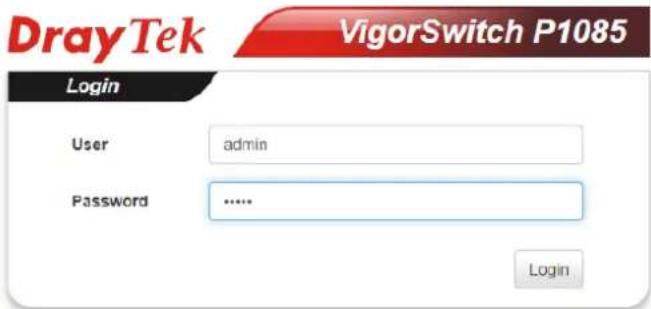
- Open any browser (e.g., Firefox) and type "192.168.1.224" as URL.
- Please type "admin/admin" as the Username/Password and click Login.
text_image
DrayTek VigorSwitch P1085 Login User admin Password ...... Login- Now, the Main Screen will appear.
text_image
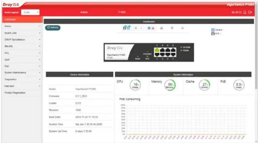
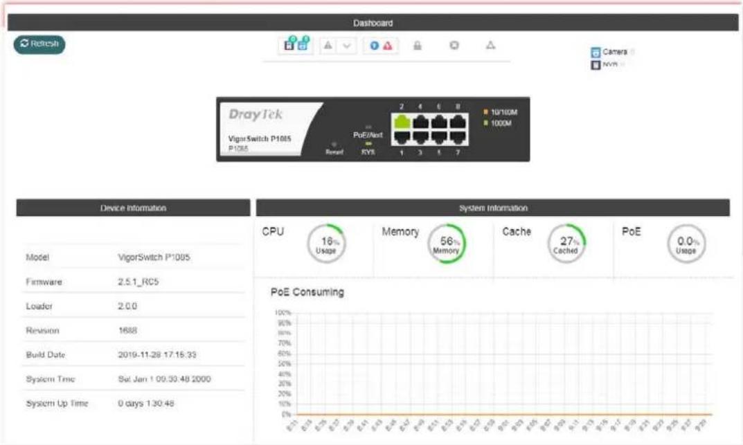
DrayTek VigerSwitch P1085 Auto Layout: 3 mm Admin P1085 99:30:52 Dashboard Status Switch LAN ONVF Surveillance Security ACL QoS PoE System Maintenance Diagnostics Mail Alert Product Registration Device Information Model VigerSwitch P1085 Firmware 2.5.1_RC5 Loader 2.0.0 Revision 1898 Build Date 2019-11-25 1/7 15:33 System Time Sat Jan 1 99:30:48 2000 System Up Time 0 days 1:30:48 System Information CPU 16% Memory 56% Cache 27% PoE 0.0% Usage Memory Memory PoE Consuming
Info
The DHCP Setting is enabled in default. Therefore, if a DHCP server presented on network connected to VigorSwitch, checking before accessing VigorSwitch is essential.
1-4 Dashboard
Click Dashboard from the main menu on the left side of the main page.

text_image
Auto Logout : 3 min Dashboard Status Switch LAN ONVIF Surveillance SecurityA web page with default selections will be displayed on the screen. Refer to the following figure:
text_image
Dashboard DrayTek VigorSwitch P1085 P1085 PuE/Ant 2 4 6 8 10'10M 100M Rerent RYS 1 3 1 7 Device Information System Information CPU 16% Usage Memory 56% Memory Cache 27% Cached PoE 0.0% Usage Model VigorSwitch P1085 Firmware 2.5.1_RC5 Loader 2.0.0 Revision 1688 Build Date 2019-11-28 17:15:33 System Time Sel Jan 1 00:30:48 2000 System Up Time 0 days 1:30:48 PoE ConsumingI-5 Status
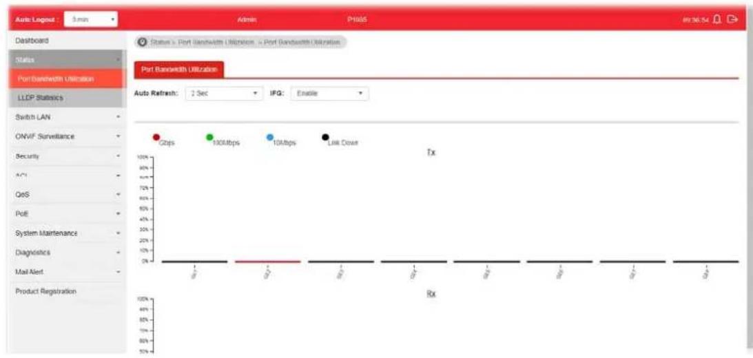
I-5-1 Port Bandwidth Utilization
This page offers the traffic statistics including data information and data of interframe gap for each port (GE1 to GE8). In which, data of interframe gap can be displayed or hidden by choose Enable / Disable for IFG.
text_image
Auto Logout - 3 min Admin PH06 89:36:54 Dashboard Status Port Bandwidth Utilization LLDP Statistics Switch LAN ONVIF Surveillance Security A*1 QoS Poll System Maintenance Diagnostics Mail Alert Product Registration Status x Port Bandwidth Utilization x Port Bandwidth Utilization Port Bandwidth Utilization Auto Refresh: 2 Sec IFG: Enable Gbps 100Mbps 10Mbps Link Down Tx RxI-5-2 LLDP Statistics
This page offers the statistics of LLDP packets (in, out and error) of each port (GE1 to GE8).

text_image
Auto Logout 3 min Dashboard Status Port Bandwidth Utilization LDDP Stationals Switch LAN ONVF Surveillance Security ACL Quit PoE System Maintenance Diagnostics Mail Alert Product Registration Status > LDDP Stationals > LDDP Stationals LDDP Stationals LDDP Global Statistics Refresh Clear All Insertions 0 Deletions 0 Drops 0 Age Outs 0 LLDP Port Statistics Port TX Frames Total RX Frames Total RX Frames Discarded RX Frames Errors RX TLVs Discarded RX TLVs Unrecognized RX Ageouts Total GE1 0 0 0 0 0 0 0 GE2 206 0 0 0 0 0 0 GE3 0 0 0 0 0 0 0 GE4 0 0 0 0 0 0 0 GE5 0 0 0 0 0 0This page is left blank.
Part II Switch LAN
II-1 General Setup
General setup is used to configure settings for the switch network interface and offers how the switch connects to a remote server to get services.
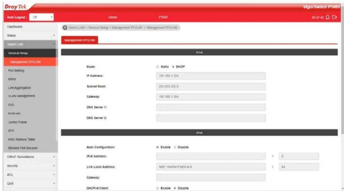
II-1-1 Management IP/VLAN
The switch needs an IP address for it to be managed over the network. The factory default IP address is 192.168.1.224. The subnet mask specifies the network number portion of an IP address. The factory default subnet mask is 255.255.255.0.
Use the IP Address (IPv4/ IPv6) screen to configure the switch IP address and the default gateway device. The gateway field specifies the IP address of the gateway (next hop) for outgoing traffic. In addition, this page allows the network administrator to change the VLAN ID of management access. Management access protocols such as http, https, SNMP and etc., are only accessible from the VLAN specified as management VLAN.

Info
If VigorSwitch has connected to Vigor router, it will use the IP address obtained from the DHCP server on Vigor router. Thus, the user must type the assigned IP as URL for accessing into the web user interface of VigorSwitch. If not, 192.168.1.224 shall be the default IP.
text_image
Dray Tek VigorSwitch P1005 Auto Logost: C/F Admin P1005 82.47.42 Dashboard Status Switch LAN General Setup Management IPWLAN Port Setting Mirror Link Aggregation VLAN Management ECE Multicast Jumbo Frame STP MAC Address Table Blocked Port Recover ONVAF Surveillance Security ACL QoS Switch LAN > General Setup > Management IPWLAN > Management IPWLAN Management IPWLAN IPV4 Node: Static DHCP IP Address: 190.158.1.124 Subnet Mask: 256.255.256.9 Gateway: 190.168.1.254 DNS Server 1: DNS Server 2: IPV6 Auto Configuration: Enable Disable IPv6 Address: / 0 Link Local Address: tel0:1643bct tel0.4c9 / 64 Gateway: DHCPv6 Client: Enable DisableAvailable settings are explained as follows:
| Item | Description |
| IPv4 | |
| Mode Select the mode of network connection.Static- Use static IPv4 address.DHCP - Use DHCP provisioned IP address and Gateway if feasible. | |
| IP Address | It is available when Static is selected as Mode.Enter the IP address of your switch in dotted decimal notation for example 192.168.1.224. If static mode is enabled, enter IP address in this field. |
| Subnet Mask | It is available when Static is selected as Mode.Enter the IP subnet mask of your switch in dotted decimal notation for example 255.255.255.0. If static mode is enabled, enter subnet mask in this field. |
| Gateway | It is available when Static is selected as Mode.Enter the IP address of the gateway in dotted decimal notation. If static mode is enabled, enter gateway address in this field. |
| DNS Server 1 | It is available when Static is selected as Mode.If static mode is enabled, enter primary DNS server address in this field. |
| DNS Server 2 | It is available when Static is selected as Mode.If static mode is enabled, enter secondary DNS server address in this field. |
| IPv6 | |
| Auto Configuration Enable | - Check it to let switch automatically configure IPv6 address. |
| IPv6 Address | It is available when Auto Configuration is set as Disable.Enter the IPv6 address of your switch. If auto configuration mode is disabled, enter IPv6 address in this field. |
| Link Local Address Display | link local address. |
| Gateway | It is available when Auto Configuration is set as Disable.Enter the IPv6 address of the router as your default IPv6 gateway to access IPv6 Internet or other IPv6 network. |
| DNS Server 1 | It is available when Auto Configuration is set as Disable.If static mode is enabled, enter primary DNS server address in this field. |
| DNS Server 2 | It is available when Auto Configuration is set as Disable.If static mode is enabled, enter secondary DNS server address in this field. |
| DHCPv6 Client | It is available when Auto Configuration is set as Enable.Enable this feature if there is a DHCPv6 server on your network for assigning IPv6 Address, instead of using Router Advertisement. |
| Management VLAN | |
| Management VLAN | Select the VLAN ID as management VLAN. You can create additional VLAN profiles by Switch LAN>>VLANmanagement>> Create VLAN. |
| Apply Apply the settings to the switch. | |
II-2 Port Setting
II-2-1 General Setting
Port Setting is used to configure settings for the switch ports, trunk, Layer 2 protocols and other switch features.

text_image
DrayTek Auto Logos: Off Admin P1003 V850 SE Dashboard Switch LAN > Port Setting > General Setting > Port Setting Status Switch LAN General Setup Port Setting General Setting Pricetled Ports Mirror Link Aggregation VLAN Management EEE Multicast Jumbo Frame STP MAC Address Table Blocked Port Recover ONVF Surveillance Security ACL Port Setting Ports: Enable State: Speed: Duplex: FlowCtrl Config FlowCtrl Status Modify GE1 Enabled Down Auto Auto Enabled Disabled ✓ GE2 Enabled Up Auto(1000M) Auto(Full) Enabled Enabled ✓ GE3 Enabled Down Auto Auto Enabled Disabled ✓ GE4 Enabled Down Auto Auto Enabled Disabled ✓ GE5 Enabled Down Auto Auto Enabled Disabled ✓ GE6 Enabled Down Auto Auto Enabled Disabled ✓ GE7 Enabled Down Auto Auto Enabled Disabled ✓Available settings are explained as follows:
| Item | Description |
| Ports Use the drop down I | st to select one or more LAN port(s). |
| Enable State Enable -Click | it to enable the port.Disable - Click it to disable the port. |
| Speed Port speed capabilities | Auto: Auto speed with all capabilities.Auto-10M: Auto speed with 10M ability only.Auto-100M: Auto speed with 100M ability only.Auto-1000M: Auto speed with 1000M ability only.Auto-10/100M: Auto speed with 10/ 100M ability.10M: Force speed with 10M ability.100M: Force speed with 100M ability.1000M: Force speed with 1000M ability.Selecting Auto (auto-negotiation) allows one port to negotiate with a peer port automatically to obtain the connection speed and duplex mode that both ends support. When auto-negotiation is turned on, a port on the switch negotiates with the peer automatically to determine the connection speed and duplex mode. If the peer port does not support auto-negotiation or turns off this feature, the switch determines the connection speed by detecting the signal on the cable and using half duplex mode. When the switch's auto-negotiation is turned off, a port uses the pre-configuredspeed and duplex mode when making a connection, thus requiring you to make sure that the settings of the peer port are the same in order to connect.For SFP fiber module, you might need to manually configure the speed to match fiber module speed. |
| Duplex Port duplex capabilities:Auto: Auto duplex with all capabilities.Half: Auto speed with 10/100M ability only.Full: Auto speed with 10/100/1000M ability only. | |
| Flow Control A concentration of traffic on a port decreases port bandwidth and overflows buffer memory causing packet discards and frame losses. Flow Control is used to regulate transmission of signals to match the bandwidth of the receiving port. The switch uses IEEE802.3x flow control in full duplex mode and backpressure flow control in half duplex mode. IEEE802.3x flow control is used in full duplex mode to send a pause signal to the sending port, causing it to temporarily stop sending signals when the receiving port memory buffers fill. Back Pressure flow control is typically used in half duplex mode to send a "collision" signal to the sending port (mimicking a state of packet collision) causing the sending port to temporarily stop sending signals and resend later.Enable - Click it to enable such function.Disable - Click it to disable such function. | |
| Apply Apply the settings to the switch. | |
Modify It is used to manually enter the description, state, speed, duplex, flow control for the port.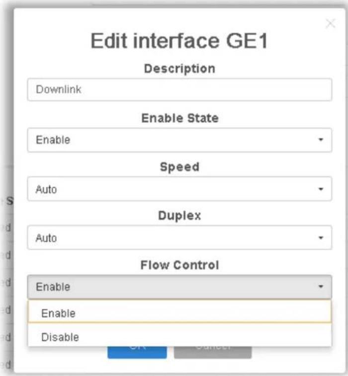 | |
II-2-2 Protected Ports
This page allows the network administrator to configure protected port setting to prevent the selected ports from communication with each other. Protected port is only allowed to communicate with unprotected port.
For example, GE1 and GE3 are selected in Port List and Enable is clicked as Protected, then users behind GE1 and GE3 are separated and can not communicate with each other.

text_image
Auto Logout : Off Admin P1000 Switch LAN + Port Setting + Protected Ports + Protected Ports Protected Ports Protected Ports Settings Port List Nothing selected Protected Enable Disable NPP+ Protected Ports Status Port Protected GE1 Disabled GE2 Disabled GE3 Disabled GE4 Disabled GE5 Disabled GE6 Disabled GE7 Disabled GE8 DisabledAvailable settings are explained as follows:
| Item | Description |
| Protected Ports Settings | ● Port List - Use the drop down list to select the port(s) (GE1 to GE8) for applying the settings configured in this page.● Protected - Click Enable to activate the protected port function.● Apply - The modification made above can be applied on to the selected GE port immediately. |
| Protected Port Status Display current status for each GE port. | |
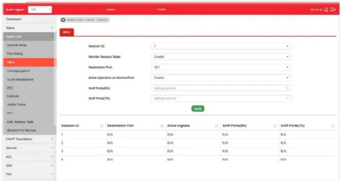
II-3 Mirror
This section provides ability to mirror packets coming in or going out on any port to a destination port. Through the packet duplication in the destination port, this feature is convenient for system administrator to monitor / understand the traffic operation.
Session ID 1 to 4 can be enabled simultaneously and operate independently.
text_image
Auto Logout : Off Admin P4088 90 67:44 Dashboard Status Switch LAN General Setup Port Setting Minor Link Aggregation VLAN Management EEE Multicast Jumbo Frame OTP MAC Address Table Blocked Port Recover Session ID: 1 Monitor Session State: Disable Destination Port: GE1 Allow Operation as Normal Port: Disable Sniff Ports(RX): Nothing selected Sniff Ports(TX): Nothing selected Apply Session ID Destination Port Allow Ingress Sniff Ports(RX) Sniff Ports(TX) 1 N/A N/A N/A N/A 2 N/A N/A N/A N/A 3 N/A N/A N/A N/A 4 N/A N/A N/A N/AAvailable settings are explained as follows:
| Item | Description |
| Session ID Select the session ID (profile 1 to 4) of mirror operation you wish to configure. | |
| Monitor Session State | ● Enable - Enable specified mirror session. ● Disable - Disable specified mirror session. |
| Destination Port Specify the port where you wish to observe the mirrored packets. | |
| Allow Operation as Normal Port | ● Enable - The destination port is able to function as a port connecting to network, communicating with other network devices. ● Disable - Only observe the mirrored packets. |
| Sniff Ports (RX) / (TX) | Select the port(s) which you wish to mirror the traffic, Rx for mirror the packets into the port, Tx for mirror the packets going out from the port. |
| Apply Apply the settings to the switch. | |
II-4 Link Aggregation
LAG means Link Aggregation Group which groups some physical ports together to make a single high-bandwidth data path. Thus it can implement traffic load sharing among the member ports in a group to enhance the connection reliability.
II-4-1 LAG Setting
This page allows to configure Load Balance Algorithm for Link Aggregation.

text_image
Auto Lognet Dashboard Status Switch LAN General Setup Port Setting Mirror Link Aggregation LAG Setting LAG Management LAG Port Setting LACP Setting LACP Port Setting VLAN Management BEE Multicast Jumbo Frame STP MAC Address Table Blocked Port Recover Adams IP3065 ON 50.67 Switch LAN - Link Aggregation - LAG Setting - LAC Setting LAG Setting Load Balance Algorithm: IP/Mac Address AddnAvailable settings are explained as follows:
| Item | Description |
| Load Balance Algorithm | Select your Load balance algorithm.MAC address- Aggregated group will balance the traffic based on different MAC addresses. Therefore, the packets from different MAC addresses will be sent to different links.IP/Mac Address- Aggregated group will balance the traffic based on MAC addresses and IP addresses. Therefore, the packets from same MAC addresses but different IP addresses will be sent to different links. |
| Apply | Apply the settings to the switch. |
II-4-2 LAG Management
There are eight LAG profiles allowed to group different physical ports (GE1 to GE8). The system will assign certain port(s) as Active Member and Standby Member according to the GE selections.

text_image
Auto Logout : Off Address P1805 20:00:43 Dashboard Status Switch LAN General Setup Port Setting Member Link Aggregation LAG Setting LAG Management LAG Port Setting LACP Setting LACP Port Setting VLAN Management EIRE Multicast Jumbo Frame: STF MAC Address Table Blocked Port Recover LAG Management LAG Description Port Type Link Status Active Member Standby Member Modify LAG1 --- Not Present ✓ LAG2 --- Not Present ✓ LAG3 --- Not Present ✓ LAG4 --- Not Present ✓ LAG5 --- Not Present ✓ LAG6 --- Not Present ✓ LAG7 --- Not Present ✓ LAG8 --- Not Present ✓Available settings are explained as follows:
| Item | Description |
| Description Display the port description. | |
| Port Type Display the type of the LAG. | |
| Link Status Display LAG port link status. | |
| Active Member | Display active member ports of the LAG. |
| Standby Member | Display inactive or candidate member ports of the LAG. |
| Modify It is used to edit the name, type and port number for each link aggregation profile. | |
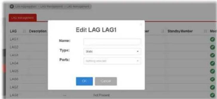 Name- Enter a string as LAG name.Type - Use the drop down menu to specify the type for LAG.● Static- The static aggregated port sends packets over active member without detecting or negotiating with remote aggregated port.● LACP- The LACP aggregated ports place member into active only after negotiated with remote aggregated port Name- Enter a string as LAG name.Type - Use the drop down menu to specify the type for LAG.● Static- The static aggregated port sends packets over active member without detecting or negotiating with remote aggregated port.● LACP- The LACP aggregated ports place member into active only after negotiated with remote aggregated port | |
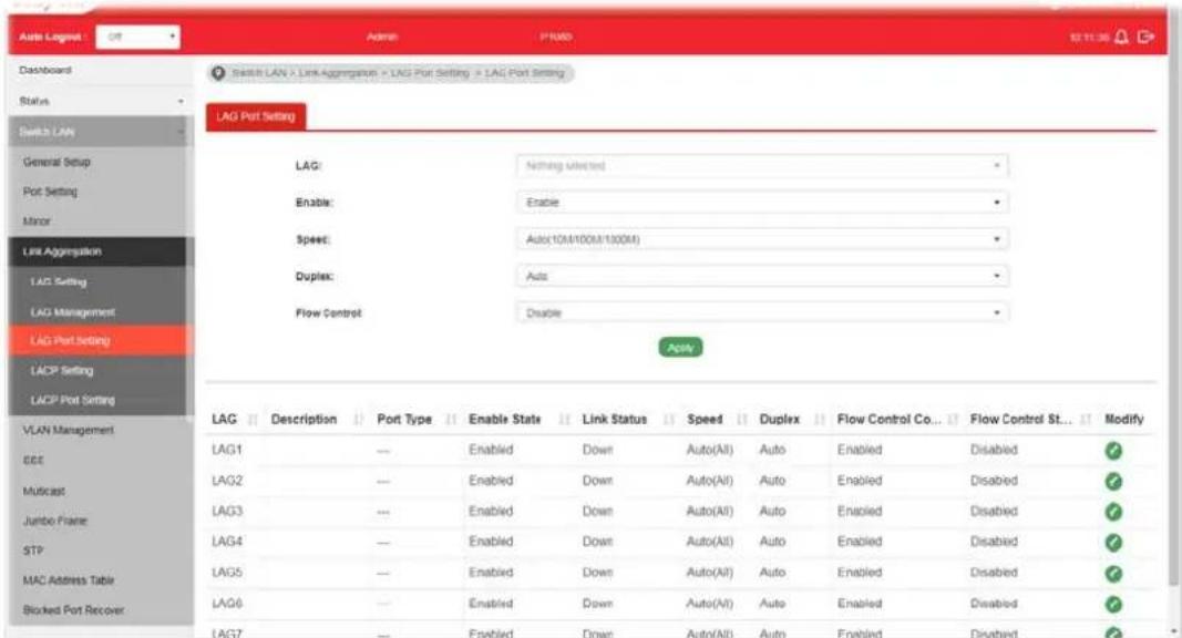
II-4-3 LAG Port Setting
This page defines port setting for each LAG profile (LAG1 to LAG8), including data speed and enabling/disabling the flow control.
text_image
Auto Logset Dashboard Status Switch LAN General Setup Port Setting Minor Link Aggregation LAG Setting LAG Management LAG Port Setting LAGP Setting LAGP Port Setting LAG Port Setting LAG: Enable: Speed: Duplex: Flow Control LAG: Nothing Untitled Enable: Enable Speed: Auto(10M/100M/100M) Duplex: Auto Flow Control: Disable LAG Description Port Type Enable State Link Status Speed Duplex Flow Control Co... Flow Control St... Modify LAG1 --- Enabled Down Auto(All) Auto Enabled Disabled ✓ LAG2 --- Enabled Down Auto(All) Auto Enabled Disabled ✓ LAG3 --- Enabled Down Auto(All) Auto Enabled Disabled ✓ LAG4 --- Enabled Down Auto(All) Auto Enabled Disabled ✓ LAG5 --- Enabled Down Auto(All) Auto Enabled Disabled ✓ LAG6 --- Enabled Down Auto(All) Auto Enabled Disabled ✓ LAG7 --- Enabled Down Auto(All) Auto Enabled Disabled ✓Available settings are explained as follows:
| Item | Description |
| LAG Use the drop down list to select one or more LAG profiles. | |
| Enable | ● Enable -Click it to enable the profile.● Disable - Click it to disable the profile. |
| Speed Port speed capabilities:● Auto(10M/100M/1000M): Auto speed with all capabilities.● Auto(10M): Auto speed with 10M ability only.● Auto(100M): Auto speed with 100M ability only.● Auto(1000M): Auto speed with 1000M ability only.● Auto(10/100M): Auto speed with 10/ 100M ability.● 10M: Force speed with 10M ability.● 100M: Force speed with 100M ability.● 1000M: Force speed with 1000M ability.Selecting Auto (auto-negotiation) allows one port to negotiate with a peer port automatically to obtain the connection speed and duplex mode that both ends support. When auto-negotiation is turned on, a port on the switch negotiates with the peer automatically to determine the connection speed and duplex mode. If the peer port does not support auto-negotiation or turns off this feature, the switch determines the connection speed by detecting the signal on the cable and using half duplex mode. When the switch's auto-negotiation is turned off, a port uses the pre-configured speed and duplex mode when making a connection, thus requiring you to make sure that the settings of the peer port | |
| are the same in order to connect.For SFP fiber module, you might need to manually configure the speed to match fiber module speed. | |
| Duplex Port duplex capabilities:Auto: Auto duplex with all capabilities.Half: Auto speed with 10/100M ability only.Full: Auto speed with 10/100/1000M / 10G ability only. | |
| Flow Control A concentration of traffic on a port decreases port bandwidth and overflows buffer memory causing packet discards and frame losses. Flow Control is used to regulate transmission of signals to match the bandwidth of the receiving port. The switch uses IEEE802.3x flow control in full duplex mode and backpressure flow control in half duplex mode. IEEE802.3x flow control is used in full duplex mode to send a pause signal to the sending port, causing it to temporarily stop sending signals when the receiving port memory buffers fill. Back Pressure flow control is typically used in half duplex mode to send a "collision" signal to the sending port (mimicking a state of packet collision) causing the sending port to temporarily stop sending signals and resend later.Enable - Click it to enable such function.Disable - Click it to disable such function. | |
| Apply Apply the settings to the switch. | |
| Modify | It is used to edit status, speed, and flow control for the LAG. |
II-4-4 LACP Setting
This page allows the network administrator to enable or disable the LACP function.

text_image
Auto Logout ACI Admin P005 10:17:42 Dashboard Status Switch LAN General Setup Port Setting Mitar Link Aggregation LAG Setting LAG Management LAG Port Setting LACP Setting LACP Port Setting VLAN Management EEE Multicast Jumbo Frame STP MAC Address Table Blocked Port Recover Buffer LAN > User Aggregation > LACP Setting > LACP Setting LACP Setting LACP: Enable Disable System Priority: 32768 (1-55535) ApplyAvailable settings are explained as follows:
| Item | Description |
| LACP | ● Enable - Click it to enable such function. ● Disable - Click it to disable the function. |
| System Priority The priority is used to determine which switch (local or remote) on the LAG connection is able to decide LACP activities. The lower the number is, the higher the priority for VigorSwitch will be. Therefore, the switch with the highest system priority (e.g., 1) can make decisions about which ports actively participate in LAG at a given time. |
| Apply Apply the settings to the switch. |
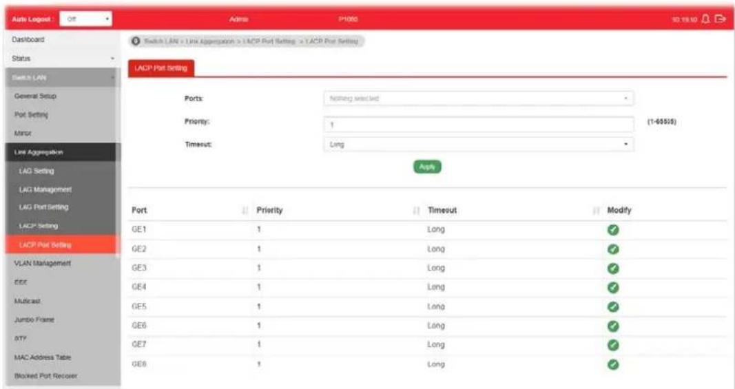
II-4-5 LACP Port Setting
This section provides few detailed configuration regarding to Ports under LACP protocol.
text_image
Auto Logpost Dashboard Status Switch LAN General Setup Port Setting Minor Link Aggregation LAG Setting LAG Management LAG Port Setting LACP Setting LACP Port Setting Ports: <|vision_start|> ramp selected Priority: 1 Timesut: Long (1-65505) Apply Port ↓ Priority ↓ Timesut ↓ Modify GE1 1 Long ✓ GE2 1 Long ✓ GE3 1 Long ✓ GE4 1 Long ✓ GE5 1 Long ✓ GE6 1 Long ✓ GE7 1 Long ✓ GE8 1 LongAvailable settings are explained as follows:
| Item | Description |
| Ports Use the drop down list to specify LAN Port. | |
| Priority Enter a port priority number for the port. | |
| Timeout The timeout option decides how local switch of LAG connection determines connection to be lost. Switch would also notify the remote switch about this setting value, so that remote switch can send LACP PDU in correct timing.Long - LACP PDU will be sent every 30 seconds. If port member is not seen over 90 seconds, it will cause port member timeout.Short - LACP PDU will be sent per second. If port member is not seen over 3 seconds, it will cause port member timeout. | |
| Apply Apply the settings to the switch. | |
| Modify It is used to edit settings (priority and timeout) for LACP port. | |
II-5 VLAN Management
A virtual local area network, virtual LAN or VLAN, is a group of hosts with a common set of requirements that communicate as if they were attached to the same broadcast domain, regardless of their physical location. A VLAN has the same attributes as a physical local area network (LAN), but it allows for end stations to be grouped together even if they are not located on the same network switch. VLAN membership can be configured through software instead of physically relocating devices or connections.
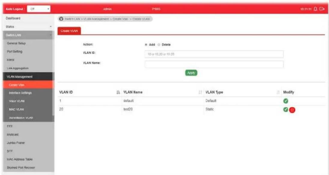
II-5-1 Create VLAN
This page allows a user to add, edit or delete VLAN settings.
text_image
Auto Logout : Off Admin PDKS 10:21:31 Dashboard Status Switch LAN General Setup Port Setting Menu Link Aggregation VLAN Management Create VLAN Action: Add Delete VLAN ID: 10 or 10.20 or 10.20 VLAN Name: Apply VLAN ID ↓ VLAN Name ↓ VLAN Type ↓ Modify 1 default Default ✓ 20 test20 Static ✓ ✓ ✓ EEE Multicast Jumbo Frame STF MAC Address Table Brookes Pvt RecoverAvailable settings are explained as follows:
| Item | Description | |||
| Action Select which action | to perform, add VLANs or delete VLANs.Add-Create a new VLAN profile.Delete-Delete an existed VLAN profile. | |||
| VLAN ID | Enter the number as VLAN ID to be created or deleted. If you want to create / delete multiple VLAN profiles, simply enter multiple VLAN ID separated by comma, and/ or range of VLAN ID using hyphen. | |||
| VLAN Name | Enter the prefix you wish to add followed by VLAN ID as VLAN name. Leave it empty for using default "VLAN".After clicking Apply, you will see: | |||
| VLAN ID | VLAN Name | VLAN Type | Modify | |
| 1 | default | Default | ||
| 2 | marketing0002 | Static | ||
| 3 | marketing0003 | Static | ||
| Apply Apply the settings to the switch. | ||||
Modify

- Modify the name of the selected VLAN ID.
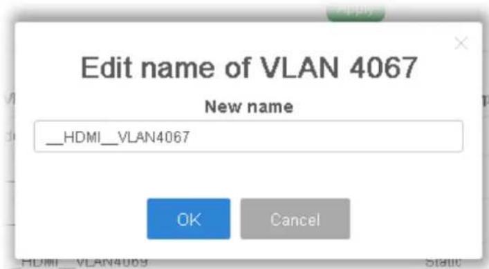
text_image
Edit name of VLAN 4067 New name __HDMI__VLAN4067 OK Cancel● New Name - Type a name for such VLAN profile.
● OK - Apply the settings to the switch.
- Cancel - Close the page and return to previous page.

- Delete the selected VALN ID.
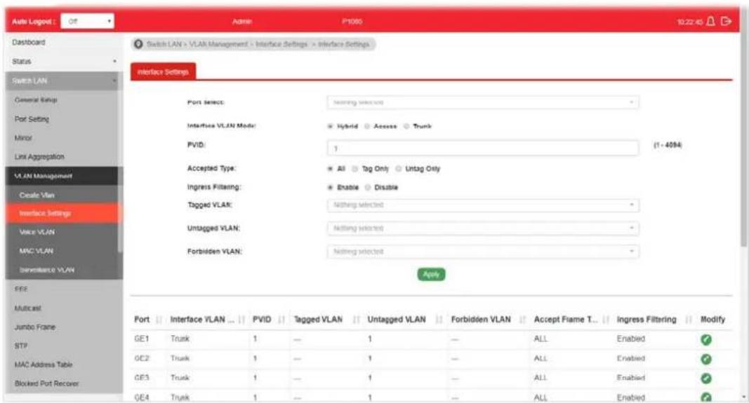
II-5-2 Interface Settings
This page allows a user to configure interface setting related to VLAN.
text_image
Switch LAN > VLAN Management > Interface Settings > Interface Settings Interface Settings Port Select: Interfice VLAN Model: Hybrid Access Trunk PVID: 1 (1 - 4094) Accepted Type: All Tag Only Untag Only Ingress Filtering: Enable Disable Tagged VLAN: Nothing selected Untagged VLAN: Nothing selected Forbidden VLAN: Nothing selected Apply Port | Interface VLAN ... | PVID | Tagged VLAN | Untagged VLAN | Forbidden VLAN | Accept Frame T... | Ingress Filtering | Modify GE1 | Trunk | 1 | — | 1 | — | ALL | Enabled | GE2 | Trunk | 1 | — | 1 | — | ALL | Enabled | GE3 | Trunk | 1 | — | 1 | — | ALL | Enabled | GE4 | Trunk | 1 | — | 1 | — | ALL | EnabledAvailable settings are explained as follows:
| Item | Description |
| Port Select Select LAN ports to configure VLAN Settings. | |
| Interface VLAN Mode Select the VLAN mode of the interface.Hybrid – Support all functions as defined in IEEE 802.1Q specification.Access – Accept only untagged frames and join an untagged VLAN. | |
| ● Trunk - An untagged member of one VLAN at most, and is a tagged member of zero or more VLANs. | |
| PVID | A PVID (Port VLAN ID) is a tag that adds to incoming untagged frames received on a port so that the frames are forwarded to the VLAN group that the tag defines.For port under Access Mode, VLAN ID provided as PVID would automatically be selected as the untagged VLAN. |
| Accepted Type Specify the | acceptable-frame-type of the specified interfaces.It's only available with Hybrid mode.All - Accept frames regardless it's tagged with 802.1q or not.Tag Only - Accept frames only with 802.1q tagged.Untag Only - Accept frames untagged. |
| Ingress Filtering Enable the | ingress filtering to filter out any packets not belong to any VLAN members of this port. It is enabled automatically while operating in Access and Trunk mode.Enabled - Click it to enable the function.Disabled - Click it to disable the function. |
| Tagged VLAN Specify the | VLAN profile tagged in the VLAN. |
| Untagged VLAN | Specify the VLAN profile untagged in the VLAN. |
| Forbidden VLAN | Specify the VLAN profile forbidden in the VLAN. |
| Apply Apply the settings to the switch. | |
| Modify | - It is used to edit settings for the selected port. |
II-5-3 Voice VLAN
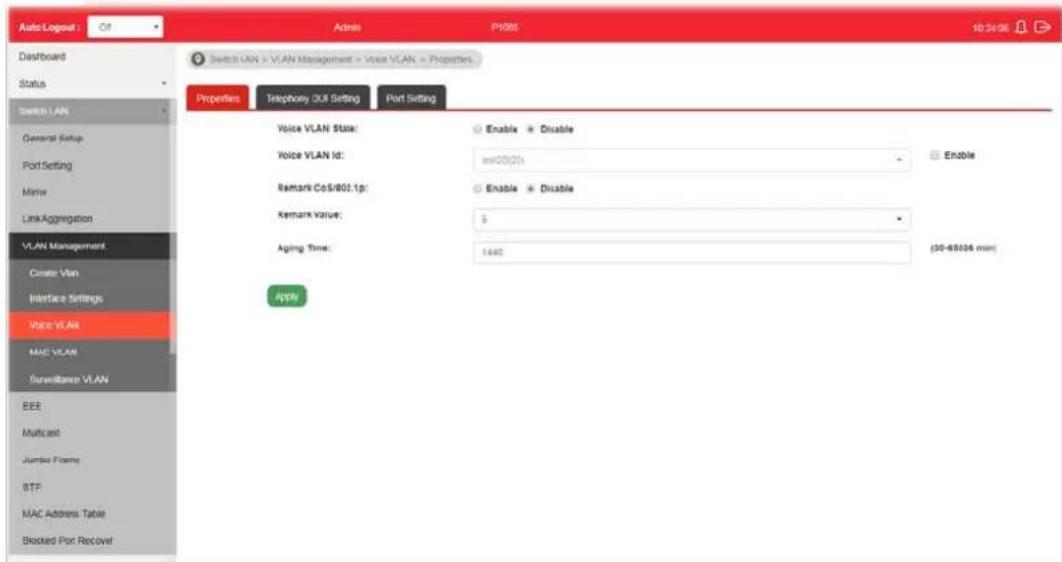
With such feature, a VLAN will be created temporarily and when the specified OUI device delivers protocol packets related to "VoIP", VigorSwitch will guide these packets into the specified Voice LAN with specified priority tag to speed up the packet transmission. Such voice VLAN is only active inside VigorSwitch for packet transmission. After these packets leave VigorSwitch, the Voice VLAN tag will be removed immediately.
II-5-3-1 Properties
This page allows a user to configure global and per interface setting of voice VLAN.
text_image
Auto Logout : Off Dashboard Status Switch LAN General Setup Port Setting Member Link Aggregation VLAN Management Create Vlan Interface Settings Voice VLAN MAC VLAN Surveillance VLAN EEE Multicast Jumbo Frame BTF MAC Address Table Blocked Port Recover Switch LAN > VLAN Management > Voice VLAN > Properties Properties Telephone Off Setting Port Setting Voice VLAN State: Enable Disable Voice VLAN Id: =00/201 Enable Disable Remark CoS/802.1p: Enable Disable Remark Value: $ Aging Time: 1440 (30-65036 min) AppleAvailable settings are explained as follows:
| Item | Description |
| Voice VLAN State | ● Enabled - Click it to enable Voice VLAN.● Disabled - Click it to disable Voice VLAN. |
| Voice VLAN Id Check the box of Enable first and then select Voice VLAN ID profile. | |
| Remark CoS/802.1p | Click Enabled / Disabled to enable or disable 1p remarking. If enabled, qualified packets will be remarked by this value. |
| Remark Value Specify the number of packets to be remarked.Specify the CoS/ 802.1p number you wish ingress VoIP packets be tagged with, so that QoS can prioritize it correctly. | |
| Aging Time | Select value of aging time (30~65536 min).Default is 1440 minutes. A voice VLAN entry will be age out after this time if without any packet pass through. |
| Apply Apply the settings to the switch. | |
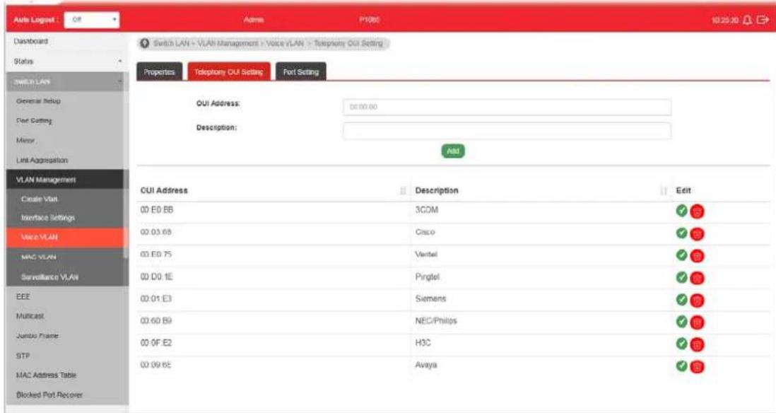
II-5-3-2 Telephony OUI Setting
This page allows a user to add, edit or delete OUI MAC addresses. Default has 8 pre-defined OUI MAC.
text_image
Auto Logged : Off Admin P1085 10:25:20 Dashboard Switch LAN - VLAN Management - Voice VLAN - Telephone OUI Setting Status Properties Telephony OUI Setting Port Setting GUI Address: 00:00:00 Description: Add VLAN Management Create Visit Interface Settings Voice VLAN MAC VLAN Surveillance VLAN EEE Multicast Jumbo Frame STP MAC Address Table Blocked Port Recover CUI Address Description Edit 00 E0 BB 3COM 00 03 68 Cisco 00 E0 75 Veritel 00 D0 1E Pingtel 00 01 E3 Siemens 00 60 B9 NEC/Philips 00 0F E2 H3C 00 09 6E AvayaAvailable settings are explained as follows:
| Item | Description |
| OUI Address Type OUI address. | |
| Description Enter a description of the specified MAC address to the voice VLAN OUI table. | |
| Add Click it to create a new voice OUI based on the settings configured above. | |
| Edit | 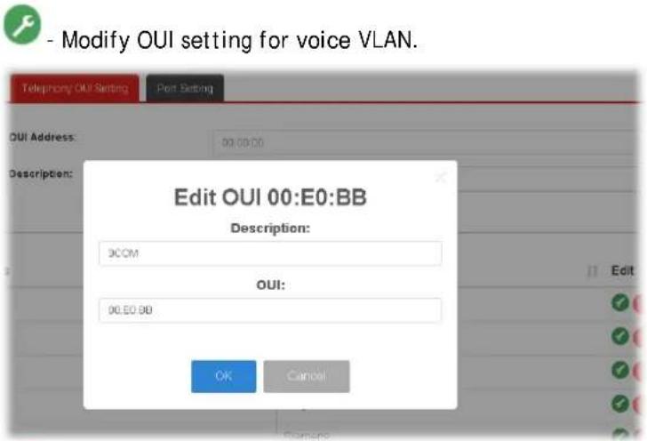 |
| - Click it to remove the selected OUI entry. | |
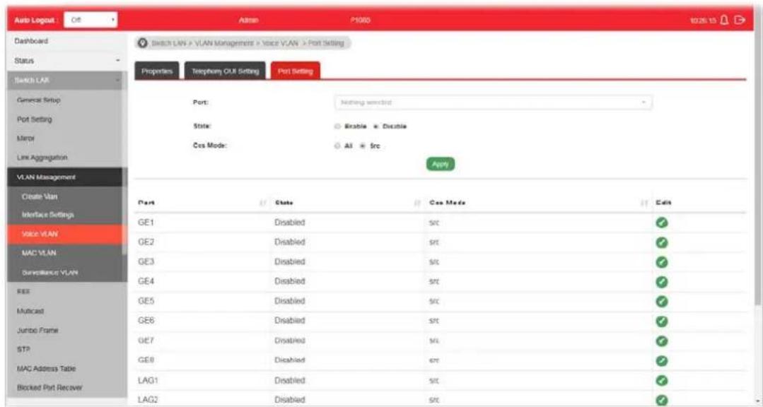
II-5-3-3 Port Setting
This page allows a user to specify LAN port(s) as Voice LAN port.
text_image
Auto Logout Dashboard Status Switch LAN General Setup Port Setting Monitor Line Aggregation VLAN Management Create Van Interface Settings Voice VLAN MAC VLAN Surveillance VLAN SEE Multicast Jumbo Frame STP MAC Address Table Blocked Port Recover Admin P1000 Switch LAN > VLAN Management > Voice VLAN > Port Setting Properties Telephone OUT Setting Port Setting Port: Nothing switched State: Enable Disable Cos Mode: All frc Apply Port State Cos Mode Edit GE1 Disabled src ✓ GE2 Disabled src ✓ GE3 Disabled src ✓ GE4 Disabled src ✓ GE5 Disabled src ✓ GE6 Disabled src ✓ GE7 Disabled src ✓ GE8 Disabled src ✓ LAG1 Disabled src ✓ LAG2 Disabled srcAvailable settings are explained as follows:
| Item | Description |
| Port Use the drop down list to specify one or more LAN ports. | |
| State | Enabled - Click it to enable the port settings for Voice LAN disabled - Click it to disable the port settings for Voice LAN. |
| Cos Mode | If Remark CoS/802.1p is enabled in Voice VLAN>>Properties, settings in this page shall be applied. Otherwise, this option will not take effect.All - Once this port is identified as Voice VLAN by frame with matched OUI, remark CoS/ 802.1p shall tag for all ingress frame regardless of remarked frame matched with pre-configured OUI or not.Src (Source) - Once this port is identified as Voice VLAN by frame with matched OUI, remark CoS/ 802.1p shall tag for only the matched ingress frame with pre-configured OUI. |
| Apply Apply the settings to the switch. | |
| Edit | Click the icon under Edit for one entry to modify port settings (State, Cos Mode) for voice VLAN. |
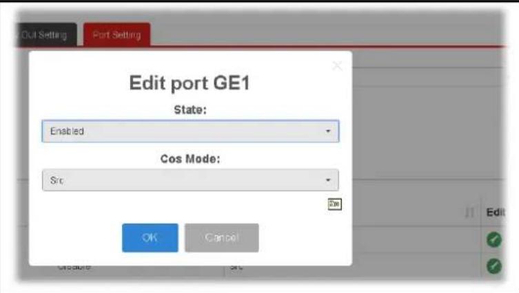
text_image
Edit port GE1 State: Enabled Cos Mode: Src OK CancelII-5-4 MAC VLAN
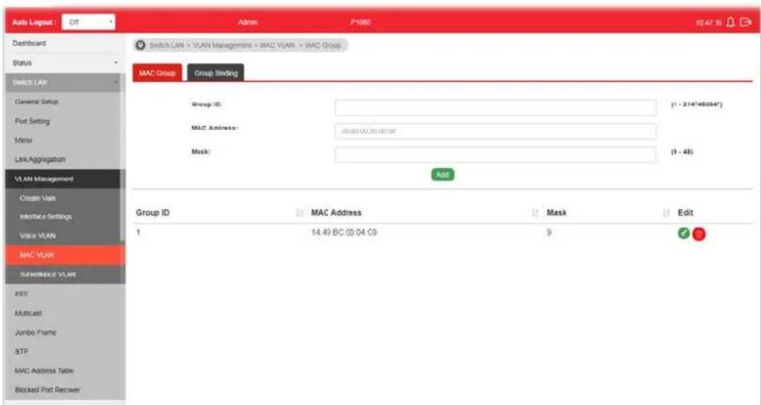
II-5-4-1 MAC Group
The MAC VLAN allows you to statically assign a VLAN ID to a host with specific MAC address(es). VigorSwitch allows you to configure multiple groups with configured MAC address and mask to be active on ports and to be bound with VLAN ID. This page allows the network administrator to define groups with specific MAC addresses for later binding with VLAN and Port.
text_image
Auto Logged OS Admin P1000 10:47:16 Dashboard Switch LAN > VLAN Management > MAC VLAN > MAC Group Status Switch LAN General Status Port Setting Mirror Link Aggregation VLAN Management Create Vlan Interface Settings Voice VLAN MAC VLAN ServerMaxn VLAN EEE Multicast Jumbo Frame STP MAC Address Table Blocked Part Recover Group ID: MAC Address: Mask: Edit 1 14.49 BC 00:04.C9 9 OKAvailable settings are explained as follows:
| Item | Description |
| Group ID It is a number for | identification later, while chosen to bebound with VLAN/ Port. |
| MAC Address | Enter the MAC address you wish to be classified in this group |
| Mask | The mask is the length of matching prefix you wish to have on MAC address.For example, configure mask in 10. It means a host with beginning of the 10-digit of MAC address will be checked, and classified into this group if matched. |
| Add Click it to create a new settings configured above. | MAC group profile based on the |
| Edit | Click the icon under Edit for one entry to modify settings for group ID. |
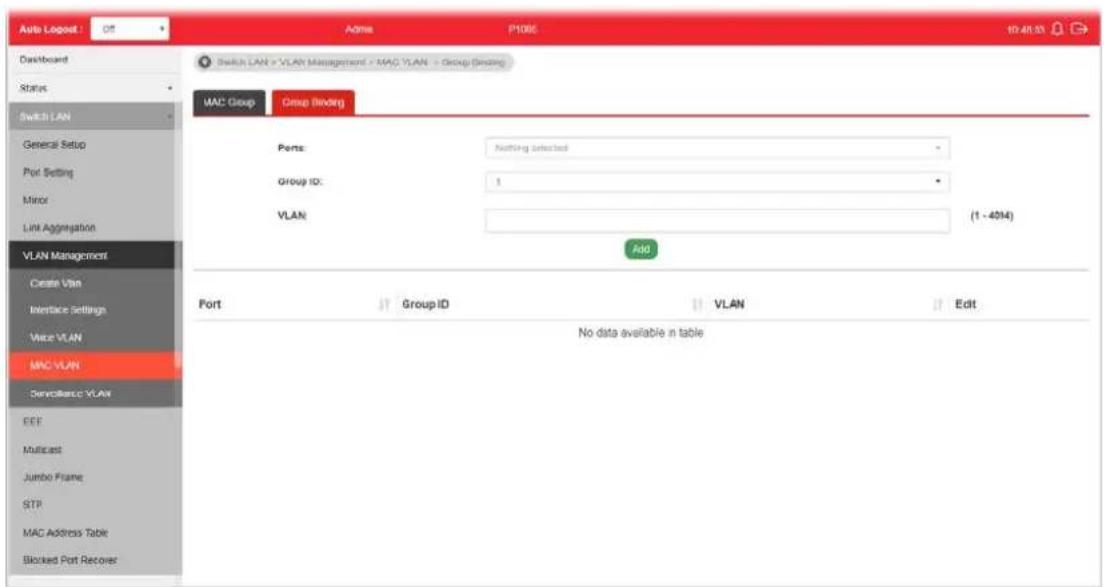
I-5-4-3 Group Binding
The MAC VLAN allows you to statically assign a VLAN ID to a host with specific MAC address(es). VigorSwitch allows you to configure multiple groups with configured MAC address and mask to be active on ports and to be bound with VLAN ID. This page allows the network administrator to bind the group of specified MAC addresses with VLAN and Port.
text_image
Auto Logost : Off ADMA P108E 10:41:23 Switch LAN > VLAN Management > MAC VLAN > Group (Binding) MAC Group Group Binding Ports: Nothing Selected Group ID: 1 VLAN (1 - 4014) Add Port Group ID VLAN Edit No data available in table EEE Multicast Jumbo Frame STR MAC Address Table Blocked Port RecoverAvailable settings are explained as follows:
| Item | Description |
| Ports Select the ports you | wish to be bound with specified MAC address group. |
| Group ID Choose the group | ID you have created in earlier section, which specified a group of host by MAC address and its mask. |
| VLAN Enter the VLAN ID that you wish to be bound with. | |
| Add Click it to create a new MAC group binding profile based on the settings configured above. | |
| Edit | Click the icon under Edit for one entry to modify settings for selected port profile. |
II-5-5 Surveillance VLAN
Surveillance VLAN can be configured for VigorSwitch to identify the packets coming from an IP camera automatically and assign those traffics to a specific VLAN ID and CoS/ 802.1p value, this helps you to prioritize those traffics and improve video quality.
II-5-5-1 Property
This page is for setting up the VLAN to which the video traffic should be assigned and to enable/disable Surveillance VLAN on each port.

text_image
Auto Logist Dashboard Status Switch LAN General Setup Port Setting Mirror Link Aggregation VLAN Management Create Vlan Interface Settings Voice VLAN MAC VLAN Surveillance VLAN GE1 GE2 GE3 GE4 GE5 GE6 GE7 GE8 State Disabled Disabled Disabled Disabled Disabled Mode Auto Auto Auto Auto Auto Auto Video Packet Video Packet Video Packet Video Packet Video Packet Video Packet Video Packet Edit Select CUI & VLAN Managerware & Surveillance VLAN > Property Property Surveillance OUT State: Enable Disable VLAN ID: Jrs00(20) CsS/802.1p Remarking: 6 Aging Time: 1480 Enable (10-68536 sec) Apply Port State Mode QoS Policy Edit GE1 Disabled Auto Video Packet ✓ GE2 Disabled Auto Video Packet ✓ GE3 Disabled Auto Video Packet ✓ GE4 Disabled Auto Video Packet ✓ GE5 Disabled Auto Video Packet ✓ GE6 Disabled Auto Video Packet ✓ GE7 Disabled Auto Video Packet ✓ GE8 Disabled Auto Video Packet ✓Available settings are explained as follows:
| Item | Description |
| State | Enabled- Click it to enable the port settings for such VLAN disabled- Click it to disable the port settings for such VLAN. |
| VLAN ID | Choose a VLAN profile (created in Switch LAN>>VLAN Management>>Create Vlan) as Surveillance VLAN. |
| CoS/802.1p Remarking | Specify the CoS/ 802.1p number you wish ingress packets be tagged with, so that QoS can prioritize it correctly.Enable- If enabled, qualified packets will be remarked by this value. |
| Aging Time Unit is second | Select value of aging time (30~65536 seconds).Default is 1440 seconds. VLAN entry will be aged out after this time if no packet passes through. |
| Apply Apply the settings to the switch. | |
| Edit | Click it to modify port setting status. |

text_image
Edit port GE1 State: Disabled Mode: Auto QoS Policy: Video Packet OK Cancel- State -Set it to enable surveillance VLAN function of interface.
● Mode -Select port surveillance VLAN mode.
Auto: Surveillance VLAN auto detect packets that match OUI table and add received port into surveillance VLAN ID tagged member.
◆ Manual: User need add interface to VLAN ID tagged member manually.
● QoS Policy - Select port QoS Policy mode.
◆ Video Packet: QoS attributes are applied to packets with OUI in the source MAC address.
◆ All: QoS attributes are applied to packets that are classified to the Surveillance VLAN. - OK - Apply the settings to the switch.
- Cancel - Abandon the changes and return to previous page.
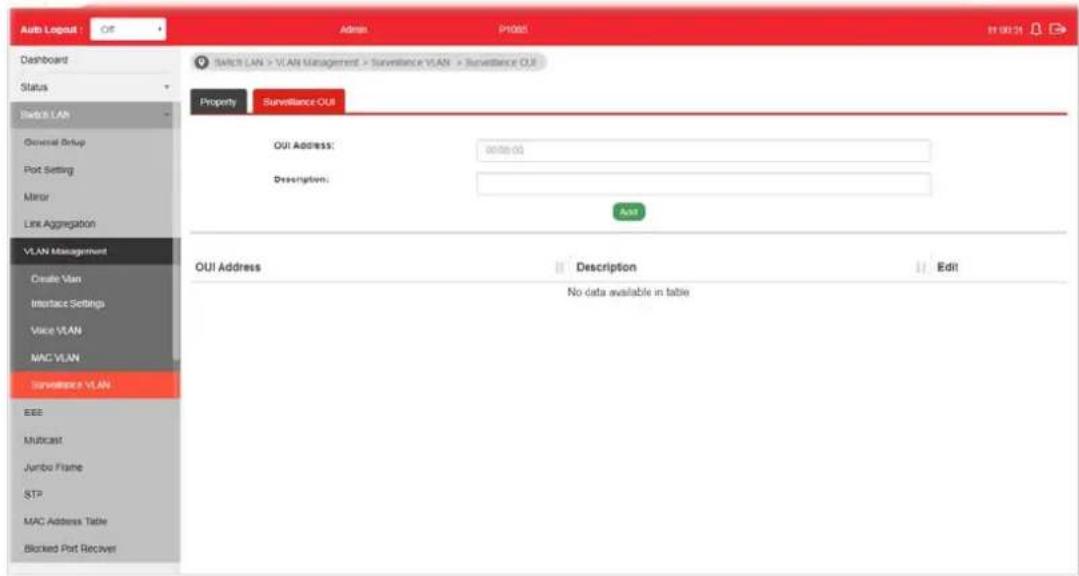
II-5-6-1 Surveillance OUI
Filtering Surveillance traffic is based on the OUI of the IP cameras. Users can add, edit, and delete OUI on this page.
text_image
Auto Logout : Off Admin P1005 11 00:21 Dashboard Status Switch LAN General Setup Port Setting Minor Link Aggregation VLAN Management Create VLAN Interface Settings Voice VLAN MAC VLAN Surveillance VLAN EEE Multicast Jumbo Frame STP MAC Address Table Blocked Port Receiver Switch LAN > VLAN Management > Surveillance VLAN > Surveillance OUI Property Surveillance OUI OUI ADDRESS: 90000.00 Description: Add OUI Address Description Edit No data available in tableAvailable settings are explained as follows:
| Item | Description |
| OUI Address Enter OUI MAC address of monitored IP camera. It can't be edited in edit dialog. | |
| Description Enter a description of the specified MAC address to the surveillance VLAN OUI table. | |
| Add Click it to create a new voice OUI based on the settings configured above. | |
| Edit | - Modify OUI setting for surveillance VLAN. - Click it to remove the selected OUI entry. |
This page allows a user to enable or disable port EEE (Energy Efficient Ethernet) function.

text_image
Auto Lognet Off Admin P1000 11:01:43 Dashboard Status Switch LAN General Setup Port Setting Mirror Line Aggregation VLAN Management EEE Multicast Jumbo Frame STP MAC Assist Table Blocked Port Recover ON/IF Surveillance Security ACL Qo5 PoE Switch LAN > EEE > Energy Efficient Ethernet Setup Energy Efficient Ethernet Setup Port: Fosting select(s) Enable Enable Disable NOM1 Port Enable Status Modify GE1 Disabled Disabled ✓ GE2 Disabled Disabled ✓ GE3 Disabled Disabled ✓ GE4 Disabled Disabled ✓ GE5 Disabled Disabled ✓ GE6 Disabled Disabled ✓ GE7 Disabled Disabled ✓ GE8 Disabled Disabled ✓Available settings are explained as follows:
| Item | Description |
| Port | Select one or multiple ports to configure (GE1 to GE8). |
| Enable | ● Enable -Click it to enable the EEE function. ● Disable - Click it to disable the EEE function. |
| Apply Apply the settings to the switch. | |
| Modify | - Click it to modify port setting status. |
II-7 Multicast
IP multicast is a technique for one-to-many communication over an IP infrastructure in a network.
To avoid the incoming data broadcasting to all GE ports, multicast is useful to transfer the data/ message to specified GE ports for IGMP snooping. When VigorSwitch receives a message "subscribed" by the client, it must decide to transfer the data to specified GE ports according to the location of the client (subscribed member).
II-7-1 Properties
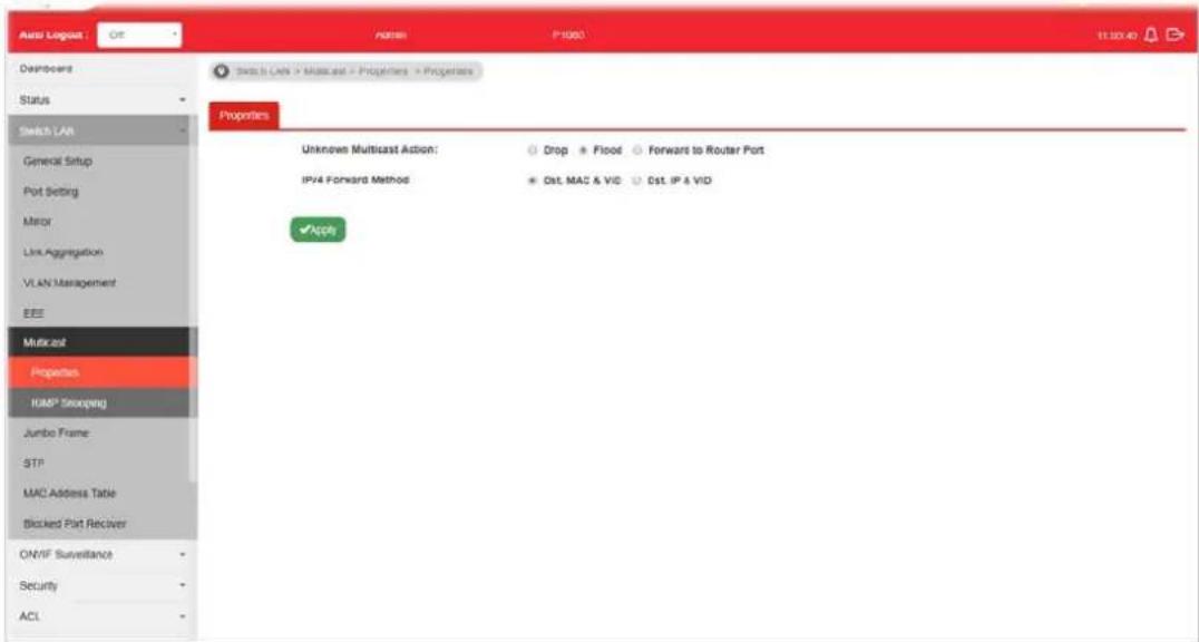
For the multicast packets, This page allows the network administrator to choose actions for processing the unknown multicast packets and for handling known packets with MAC address, IP address and VLAN ID.
text_image
Auto Loglog : Off ADAMS P1000 11:30:40 Downloads Status Switch LAN General Setup Port Setting Mirror Link Aggregation VLAN Management EEE Multiplet Properties HMP Seoqing Jumbo Frame: STP MAC Address Table Blocked Part Receiver ON/IF Surveillance Security ACL Switch LAN > Multiplet > Properties > Properties Unknown Multicast Action: Drop + Flood Forward to Router Port IPv4 Forward Method Cst. MAC & VID Cst. IP & VID AppleAvailable settings are explained as follows:
| Item | Description |
| Unknown Multicast Action | Select an action for switch to handle with unknown multicast packet.Drop: Drop the unknown multicast data.Flood: Flood the unknown multicast data.Forward to Router port: Forward the unknown multicast data to router port. |
| IPv4 Forward Method Set | the IPv4 multicast forward method.Dst. MAC & VID: Forward using destination multicast MAC address and VLAN IDs.Dst. IP & VID: Forward using destination multicast IP address and VLAN ID. |
| Apply Apply the settings to the switch. | |
II-7-2 IGMP Snooping
IGMP snooping is the process of listening to Internet Group Management Protocol (IGMP) network traffic. The feature allows a network switch to listen in on the IGMP conversation between hosts and routers. By listening to these conversations the switch maintains a map of which links need which IP multicast streams. Multicasts may be filtered from the links which do not need them and thus controls which ports receive specific multicast traffic.

flowchart
graph TD
    A["Source"] --> B["Vigor router"]
    B --> C["VigorSwitch"]
    C --> D["Host A"]
    C --> E["Host B"]
    C --> F["Host C"]
    G["PIM (IPv4)"] --> B
    style A fill:#f9f,stroke:#333
    style B fill:#ccf,stroke:#333
    style C fill:#cfc,stroke:#333
    style D fill:#fcc,stroke:#333
    style E fill:#fcc,stroke:#333
    style F fill:#fcc,stroke:#333
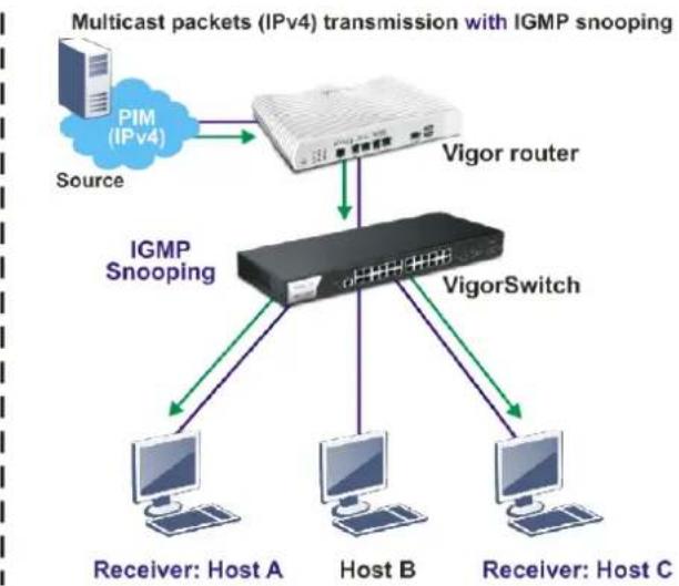
flowchart
graph TD
    A["Source"] --> B["Vigor router"]
    B --> C["IGMP Snooping"]
    C --> D["Host A"]
    C --> E["Host B"]
    C --> F["Host C"]
    B --> G["VigorSwitch"]
    style A fill:#f9f,stroke:#333
    style B fill:#ccf,stroke:#333
    style C fill:#cfc,stroke:#333
    style D fill:#fcc,stroke:#333
    style E fill:#fcc,stroke:#333
    style F fill:#fcc,stroke:#333

II-7-2-1 IGMP Setting
This page allows the network administrator to enable/disable IGMP function, select snooping version, and enable/disable snooping report suppression.

text_image
Auto Legend : Off Admin PDB 13245 Dashboard Switch LAN > Multicast > IGMP Snooping > IGMP Setting Status Switch LAN General Setup Port Setting Mirror Link Aggregation VLAN Management EEE Multicast Properties IGMP Snooping Jumbo Frame STP MAC Address Table Blocked Port Receiver ONVF Surveillance Security ACL Switch LAN > Multicast > IGMP Snooping > IGMP Setting IGMP Setting IGMP Queue Setting IGMP Static Group IGMP Group Table IGMF Router Table Global Setting IGMP Snooping State: Enable Disable IGMP Snooping Version: v2 v2 (B$5) IGMP Snooping Report Suppression: Enable Disable Appl VLAN Setting Entry No. VIAN ID IGMP Snoopi... Router Ports... Query Robus... Query Interva... Query Max R... Last Member... Last Member... 1 1 Disabled Enabled 2 125 10 2 1 2 20 Disabled Enabled 2 125 10 2 1Available settings are explained as follows:
| Item | Description |
| IGMP Snooping State | ● Enable - Click it to set enabling IGMP function.● Disable - Click it to disable IGMP function. |
| IGMP Snooping Version Set the IGMP snooping version.● v2 - Only support process IGMP v2 packet.● v3 (BISS) - Support v3 basic and v2. | |
| IGMP Snoopign Report Suppression | Click Enable to allow the switch to handle IGMP reports between router and host, suppressing bandwidth used by IGMP. |
| Apply Apply the settings to the switch. | |
| Modify | ● - Click it to modify IGMP settings for selected profile. However, if IGMP Snooping State is not set as Enable, such option will be disabled. |
| Edit VLAN ID 1IGMP Snooping StateDisableRouter Ports Auto LearnEnableQuery Robustness (Operational: 2)2 [4-74] (1-7, default 2)Query Interval (Operational: 125)125 [T9/12] Sec (30-18000, default 125)Query Response Interval (Operational: 10)10 [27-60] Sec (5-20, default 10)Last Member Query Counter (Operational: 2)2 [6-36] Sec (1-7, default 2)Last Member Query Interval (Operational: 1)1 [10-12] Sec (1-25, default 1)Immediate Leave:EnableG42W] Cancel | |
| ● IGMP Snooping State -Choose Enable to enable IGMP snooping function.● Router Ports Auto Learn - Set the enabling status of IGMP router port learning. Choose Enable to learn router port by IGMP query.● Query Robustness - Set a number which allows tuning for the expected packet loss on a subnet.● Query Interval - Set the interval of querier send general | |
Edit VLAN ID 1
IGMP Snooping State
Router Ports Auto Learn
Query Robustness (Operational: 2)
Query Interval (Operational: 125)
Query Response Interval (Operational: 10)
Last Member Query Counter (Operational: 2)
Last Member Query Interval (Operational: 1)
Immediate Leave:
- IGMP Snooping State -Choose Enable to enable IGMP snooping function.
- Router Ports Auto Learn - Set the enabling status of IGMP router port learning. Choose Enable to learn router port by IGMP query.
- Query Robustness - Set a number which allows tuning for the expected packet loss on a subnet.
- Query Interval - Set the interval of querier send general
| query.●Query Response Interval- It specifies the maximum allowed time before sending a responding report in units of 1/10 second.●Last Member Query Counter- After quering for specified times (defined here) and still not receiving any response from the subscribed member, VigorSwitch will stop transmitting data to the related GE port(s).●Last Member Query Interval- The maximum time interval between counting each member query message with no responses from any subscribed member.●Immediate Leave- Leave the multicast group immediately on the port & VLAN where leave message is sent from, regardless there is still a subscribed member or not. Click Enable to enable Fastleave function.●OK- Apply the settings to the switch.●Cancel- Close the page and return to previous page. |
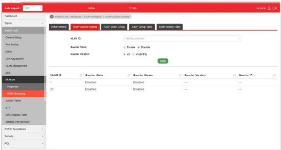
II-7-2-2 IGMP Querier Setting
This page allows a user to configure querier settings on specific VLAN of IGMP Snooping.
text_image
Auto Legend : Off Admin P4M6 11:30:30 Dashboard Switch LAN > Multicast > ICMP Shipping > ICMP Quiver Setting Status Switch LAN General Setup Port Setting Minor Last Aggregation VLAN Management EEE Multicast Properties KMP Shipping Jumbo Frame STP MAC Address Table Blocked Port Recover ON/IF Surveillance Security ACL Switch LAN > Multicast > ICMP Shipping > ICMP Quiver Setting IGMP Setting IGMP Quiver Setting IGMP Static Group IGMP Group Table IGMP Router Table VLAN ID: Nothing selected Quiver State: Enable Disable Quiver Version: v2 v3 ($155) Apple VLAN ID Quiver State Quiver Status Quiver Version Quiver IP 1 Disabled Disabled — — 20 Disabled Disabled — —Available settings are explained as follows:
| Item | Description |
| VLAN ID | Use the drop down list to specify a VLAN profile as IGMP Snooping querier. |
| Querier State | Enable - Click Enable to set the enabling status of IGMP Querier on the chosen VLAN profile.Disable - Click it to disable the function. |
| Querier Version Set the query version of IGMP Querier Election on the chosen VLANs.v2 - Querier version 2.v3 - Querier version 3.Note: For maximum compatibility, it is suggested to use querier version lower than IGMP snooping version, for there is possible network mixed with IGMP v2/ v3 client and v2 query | |
| message is widerly understandable for those clients. | |
| Apply Apply the settings to the switch. | |
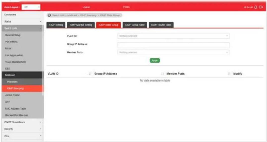
II-7-2-3 IGMP Static Group
The IGMP static group is allowed to assign a VLAN/ port as a specific IPv4 multicast member. Every IPv4 multicast stream that belongs to the specified group IP address will be forwarded to the specified port/ VLAN member.
text_image
Auto Lognet Defaulted Status Switch LAN General Setup Plot Setting Minor Link Aggregation VLAN Management EEE Multicast Properties IGMP Slooping Jumbo name BTP MAC Address Table Blocked Port Recover ONMF Surveillance Security ACL Switch LAN > Multicast > IGMP Slooping > IGMP State Group IGMP Setting IGMP Gainer Setting IGMP State Group IGMP Group Table IGMP Router Table VLAN ID: Nothing selected Group IP Address: Member Ports: Nothing selected Apps VLAN ID Group IP Address Member Ports Modify No data available in tableAvailable settings are explained as follows:
| Item | Description |
| VLAN ID | Use the drop down list to specify a VLAN profile as IGMP Static Group. |
| Group IP Address It is an id | identifier for the group member. Packets sent to such address will be transferred to all interfaces defined in Member Ports.Specify the IPv4 multicast address you wish to assign for the static group (defined in VLAN ID). |
| Member Ports Specify the | port(s) that static group with given IPv4 multicast address shall include. |
| Apply Apply the settings to | the switch. |
| Modify | - Click it to modify settings. |
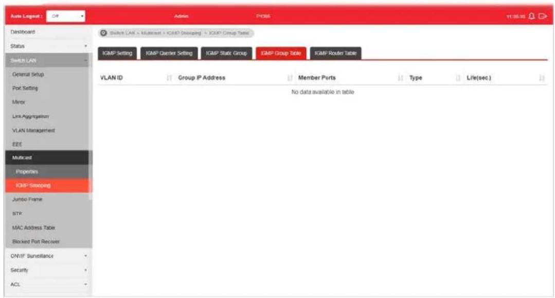
II-7-2-4 IGMP Group Table
This page shows currently known and dynamically learned by IGMP snooping or shows the assigned IPv4 multicast address group in operation.
text_image
Auto Loglog: Off Admin PDBS 11:35:35 Dashboard Status Switch LAN General Setup Port Setting Minor Link Aggregation VLAN Management EEE Multicast Properties ICMP Steering Jumbo Frame STP MAC Address Table Blocked Port Receiver ONIF Surveillance Security ACL Switch LAN - Multicast - IGP0 Steering - IGP7 Group Table IGMP Setting IGMP Carrier Setting IGMP Stack Group IGMP Group Table IGMP Router Table VLAN ID Group IP Address Member Ports Type Life(sec) No data available in tableAvailable settings are explained as follows:
| Item | Description |
| VLAN ID | Display the VLAN of this multicast group belongs to. |
| Group IP Address | Display the multicast address of this multicast group. |
| Member Ports Display the port(s) where subscribing member of this multicast group belongs to. | |
| Type Display if it is dynamically learned or statically assigned. | |
| Life(sec.) Display the life time of this multicast member left if no membership report sent again. | |
II-7-2-5 IGMP Router Table
This page shows the IGMP querier router known to this switch.
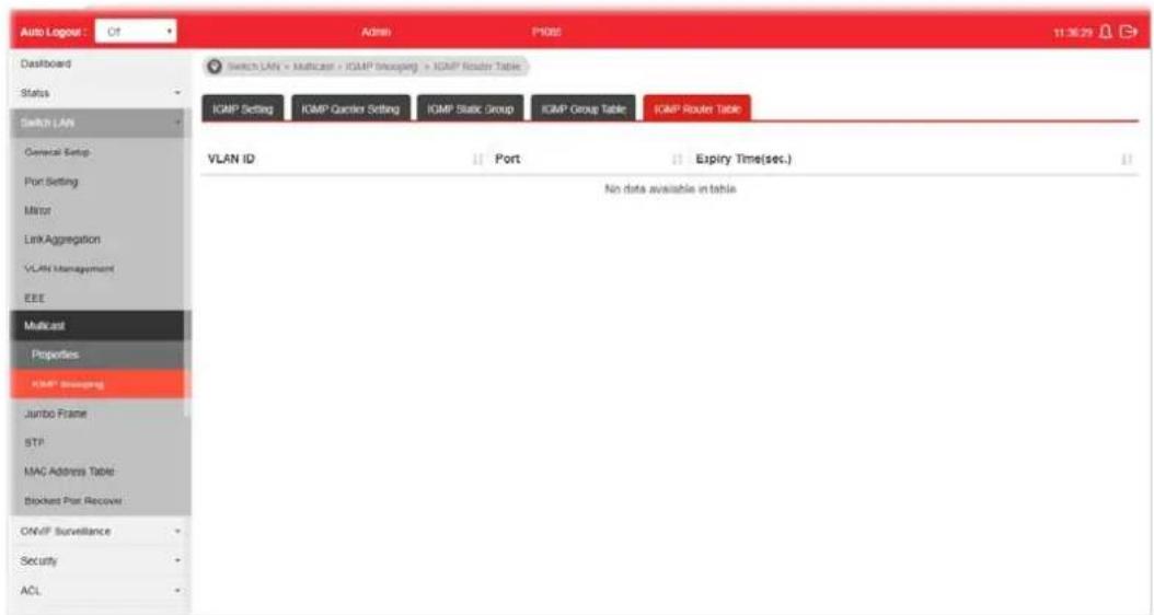
text_image
Auto Logger: Of Admin P002 11:30:29 Dashboard Status Switch LAN General Setup: Port Setting Minor Link Aggregation VLAN Management EEE Multicast Properties ICMP Shipping Jumbo Frame STP MAC Address Table: Blockets Port Recover ONVIF Surveillance Security ACL Switch LAN = Multicast + ICMP Shipping + ICMP Router Table ICMP Setting ICMP Request Setting ICMP Static Group ICMP Group Table ICMP Router Table VLAN ID Port Expiry Time(sec.) No data available in tableAvailable settings are explained as follows:
| Item | Description |
| VLAN ID | Use the drop down list to specify a VLAN profile (created in Switch LAN>>VLAN Management>>Create Vlan) that the MLD querier belongs to. |
| Port Display the static port | member specified in Member Ports. |
| Expire Time (sec.) | Display the time before querier is considered no longer existed. |
II-8 Jumbo Frame
This page allows a user to configure switch port jumbo frame settings.
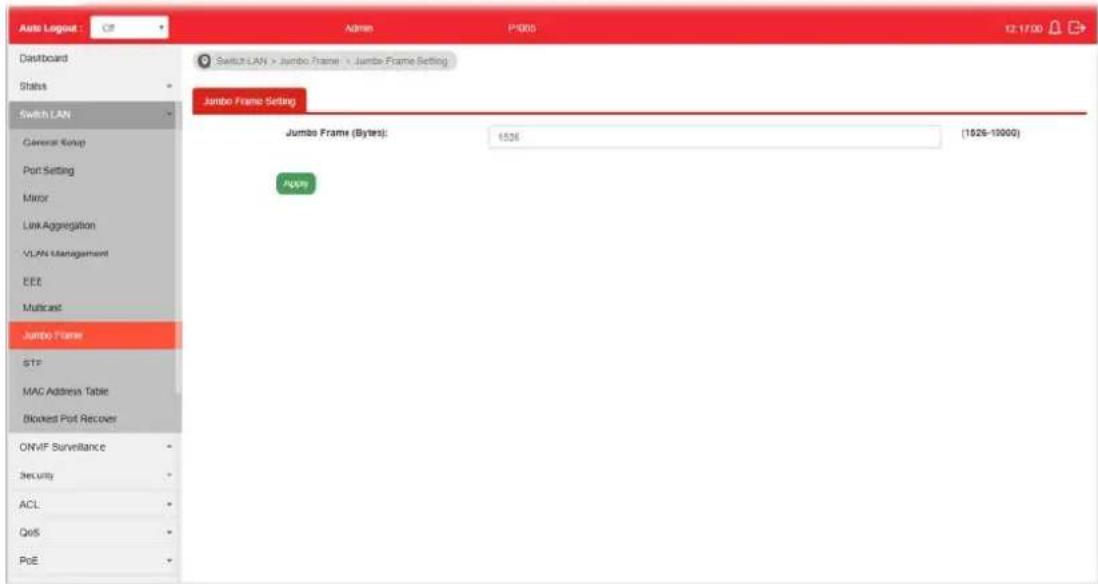
text_image
Auto Loglog : C8 Admin P3000 12:17:00 Dashboard Status Switch LAN General Setup Port Setting Mirror Link Aggregation VLAN Management EEE Multicast Jumbo Frame STF MAC Address Table Blocked Port Recover ONVIF Surveillance Security ACL QoS PoE Switch LAN > Jumbo Frame > Jumbo Frame Setting Jumbo Frame Setting Jumbo Frame (Bytes): 1526 (1526-10000) ApplyAvailable settings are explained as follows:
| Item | Description |
| Jumbo Frame (Bytes) Enter Jumbo frame size. The valid range is 1526 bytes - 10000 bytes. | |
| Apply Apply the settings to the switch. | |
II-9 STP
The Spanning Tree Protocol (STP) is a network protocol that ensures a loop-free topology for any bridged Ethernet local area network.
Bridge Protocol Data Units (BPDUs) are frames that contain information about the Spanning Tree Protocol (STP). Switches send BPDUs using a unique MAC address from its origin port and a multicast address as destination MAC (01:80:C2:00:00:00, or 01:00:0C:CC:CC:CD for Per VLAN Spanning Tree).
For STP algorithms to function, the switches need to share information about themselves and their connections. What they share are bridge protocol data units (BPDUs).
BPDUs are sent out as multicast frames to which only other layer 2 switches or bridges are listening. If any loops (multiple possible paths between switches) are found in the network topology, the switches will co-operate to disable a port or ports to ensure that there are no loops; that is, from one device to any other device in the layer 2 network, only one path can be taken.
II-9-1 Properties
This page allows a user to configure and display Spanning Tree Protocol (STP) property configuration.
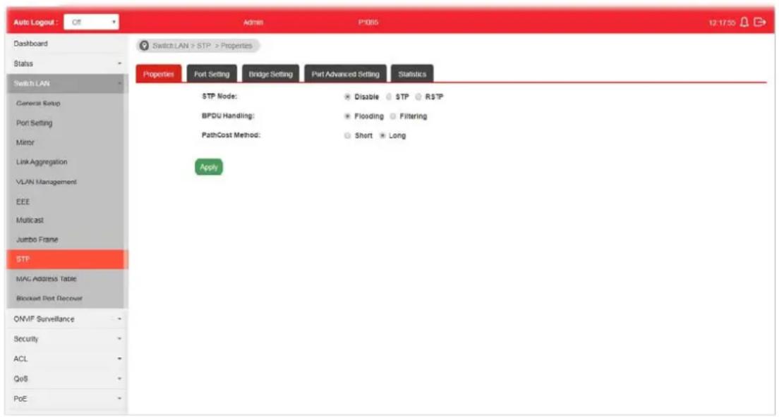
text_image
Auto Logout : Off Admin P1085 12:17:50 Dashboard Status Switch LAN General Setup Port Setting Mirror Link Aggregation VLAN Management EEE Multicast Jumbo Frame STP MAG Address Table Blockout Port Recover ONVF Surveillance Security ACL QoS PoE Switch LAN > STP > Properties Properties Port Setting Bridge Setting Port Advanced Setting Statistics STP Mode: Disable TP RTP BPDU Handling: Flooding Filtering PathCost Method: Short Long ApplyAvailable settings are explained as follows:
| Item | Description |
| STP Mode Set the operating mode of Spanning Tree (STP).● Disabled - Disable the STP operation.● STP - Enable the Spanning Tree (STP) operation.● RSTP - Enable the Rapid Spanning Tree (RSTP) operation. | |
| BPDU Handling Specify the BPDU forward method when the STP is disabled.● Filtering - Filter the BPDU when STP is disabled.● Flooding - Flood the BPDU when STP is disabled. | |
| PathCost Method Specify the path cost method.● Long - Specifies that the default port path costs are within the range: 1~200,000,000.● Short - Specifies that the default port path costs are within the range: 1~65,535. | |
| Apply Apply the settings to the switch. | |
II-9-2 Port Setting
This page allows the user to configure and display Spanning Tree Protocol (STP) port settings.

text_image
Auto Lognut Dashboard Status Switch LAN General Setup Port Setting MER Link Aggregation VLAN Management EEE Multicast Jumbo Frame STP MAC Address Table Blocked Port Recover ONVIF Surveillance Security ACL QoS PoE Switch LAN > STP > Port Setting Properties Port Setting Bridge Setting Part Advanced Setting Statistics Ports: Nothing selected Path Cost (0 = Auto): 0 Priority: 126 Edge Port: Yes No P2P Option: Auto Yes No BPDU Filter: Yes BPDU Guard: Yes Apply Ports: Nothing selected Migrain Port Admin Enable Path Cost Priority Edge Port F2P Option BPDU Filter BPDU Guard Edit GE1 Enabled 0 128 No Auto Disabled Disabled ✓ GE2 Enabled 0 128 No Auto Disabled Disabled ✓Available settings are explained as follows:
| Item | Description |
| Ports Use the drop down to specify the interface ID or the list of interface IDs. | |
| Path Cost (0=Auto) | Path cost is the cost of transmitting a frame on to a LAN through that port. It is recommended to assign this value according to the speed of the bridge. The slower the media, the higher the cost. Entering 0 means the switch will automatically assign a value. |
| Priority | Specify a priority value for the switch. The smaller the priority value, the higher the priority and greater chance of becoming the root. |
| Edge Port In the edge mode, the interface would be put into the Forwarding state immediately upon link up. If the edge mode is enabled for the interface and there are BPDUs received on the interface, the loop might be occurred in the short time before the STP state change.Yes - Enable the function.No - Disable the function. | |
| P2P Option | Auto - VigorSwitch determines the STP of link type for this port automatically.Yes - It means the STP of link type on this port isfull-duplex and directly connect to another switch or host.No - It means the STP of link type on this port is “not” full-duplex and “does not” directly connect to another switch or host. |
| BPDU Filter | Yes - Drop all BPDU packets and no BPDU will be sent. |
| BPDU Guard Yes - BPDU Guard further protects your switch by turning this port into error state and shutdown if any BPDU received from this port. Check it to enable such function. | |
| Apply Apply the settings to the switch. After clicking it, the settings configured above will be shown on the table below. | |
| Ports | Use the drop down to specify the interface(s) for applying the function ofMigrate. |
| Migrate Click it to force the port(s) specified above to send one RSTP BPDU (Rapid Spanning Tree Protocol Bridge Protocol Data Unit). | |
| Edit Click it to modify the settings for the selected GE port. | |
II-9-3 Bridge Setting
This page allows the network administrator to configure required information to negotiate with other VigorSwitch for determining the bridge switch.

text_image
Auto Legend Dashboard Status Switch LAN General Setup Port Setting Matrix Link Aggregation VLAN Management EEE Multicast Jumbo Frame STP MAC Address Table Blocked Port Decouer ONMT Surveillance Security ACL QoS POE Switch LAN > STP > Bridge Setting Properties Port Setting Bridge Setting Port Advanced Setting Statistics Priority: 32769 Forward Delay: 15 Max Age: 20 Tx Hold Count: 6 Hello Time: 3 Appb Bridge Identifier 32768/ 0/14.49 BC 00 M C9 Designated Root Bridge 0/000 00 00 00 00 00 Root Path Cost 0 Designated Bridge 0/000 00 00 00 00 00 Root Port 0 / 0 Max Hops 26 Remaining Hops 0 Last Topology Change 0Available settings are explained as follows:
| Item | Description |
| Priority Specify the bridge | priority. The valid range is from 0 to 61440, and the value should be the multiple of 4096. It ensures the probability that the switch is selected as the root bridge, and the lower value has the higher priority for the switch to be selected as the root bridge of the topology. |
| Forward Delay Specify the | STP forward delay time, which is the amount of time that a port remains in the Listening and Learning states before it enters the Forwarding state. Its valid range is from 4 to 10 seconds. |
| Max Age Specify the time | nterval in seconds for a switch to wait the configuration messages, without attempting to redefine its own configuration. |
| Tx Hold Count Specify the | tx-hold-count used to limit the maximum numbers of packets transmission per second. The valid range is from 1 to 10. |
| Hello Time | Specify the STP hello time in second to broadcast its hello message to other bridge by Designated Ports. Its valid range is from 1 to 10 seconds. |
| Apply Apply the settings to | the switch. |
II-9-4 Port Advanced Setting
This page allows user to edit general setting of STP CIST port and browser CIST port status.

text_image
Auto Logout Dashboard Status Switch LAN General Status Port Setting Mover Link Aggregation VLAN Management ECE Multirail Jumbo frame STP MAC Address Table Blocked Port Recover ONVP Surveillance Security ACL GoS Port System Maintenance Diagnostics Mail Alert Admin P-006 Switch LAN > STP > Port-Advanced Setting Properties Port Setting Bridge Setting Port-Advanced Setting Statistics Port Identifier (Priority/ID) Path Cost Cont/Oper Designated Ro... Root Path Cost Designated BRI... Edge Part Cont/Oper P2IP Option Cont/Oper Port Role Port State Edit GE1 GE2 GE3 GE4 GE5 GE6 GE7 GE8 LAG1 LAG2 LAG3 LAG4 LAG5 LAG6 LAG7 LAG8 Indentifier (Priority/ID) 0 / 200000 0 / 00:00:00:00:00:00:00:00:00:00:00:00:00:00:00:00:00:00:00:00:00:00:00:00:00:00:00:00:00:00:00:00:00:00: 128 / 1 3 / 200000 3 / 200000 3 / 200000 3 / 200000 3 / 200000 3 / 200000 3 / 200000 3 / 200000 3 / 200000 3 / 200000 3 / 200001 3 / 20016 3 / 2016 3 / 2016 3 / 2016 3 / 2016 3 / 2016 3 / 2016 3 / 2016 3 / 2016 3 / 2016 3 / 2016 3 / 2016 3 / 2016Available settings are explained as follows:
| Item | Description |
| Port Display the interface | number for GE and LAG. |
| Indentifier(Priority/ID) | Display the spanning tree port identifier. |
| Path Cost Conf/Oper | Display current path cost of given port. |
| Designated Root Bridge | display the identifier of designated root bridge. |
| Root Path Cost Display the | operational root path cost. |
| Designated Bridge Display | the identifier of next bridge on this port. |
| Edge Port Conf/Oper | Display if this port is configured as Edge of STP network, for speed up link up. |
| P2P MAC Conf/Oper | Display if this port is configured as point to point link to another switch or host. |
| Port Role Display current | port role on the specified port. The possible values will be: “Disabled”, “Root”, “Designated”, “Alternative”, and “Backup”. |
| Port State Display current | port state on the specified port. The possible values will be: “Disabled”, “Discarding”, “Learning”, and “Forwarding”. |
| Edit Click it to modify the | priority setting for the selected GE port / LAG port. |
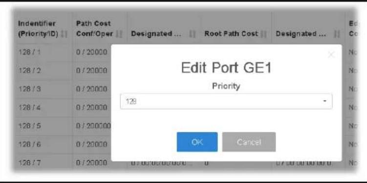
text_image
Edit Port GE1 Priority 128 OK CancelII-9-5 Statistics
This page displays STP statistics.

text_image
Auto Logpost Off Admin P1006 12:36:18 Dashboard Switch LAN > STP > Statistics Status Switch LAW General Setup Port Setting Miner Link Aggregation VI All Management EEE Multicaid Junto Frame SIP MAC Address Table Blocked Port Receiver ON/IF Surveillance Security ACL QoS Port System Maintenance Diagnostics Mail Alert Port Configure BPDUs Rx. TCN BPDUs Rx. Configure BPDUs Tx. TCN BPDUs Tx. GE1 GE2 GE3 GE4 GE5 GE6 GE7 GE8 LAG1 LAG2 LAG3 LAG4 LAG5 LAG6 LAG7 LAG8 Configure BPDUs Rx. Configure BPDUs Tx. 0 0 0 0 0 0 0 0 0 0 0 0 0 0 0 0 0 0 0 0 0 0 0 0 0 0 0 0 0 0 0 0 0 0 0 0 0 0 0 0 0 0Available settings are explained as follows:
| Item | Description |
| Port Display the port number (GE / LAG). | |
| Configure BPDUs Rx. | Display the counts of the received CONFIG BPDU. |
| TCN BPDUs Rx. | Display the counts of the received TCN BPDU. |
| Configure BPDUs Tx. | Display the counts of the transmitted CONFIG BPDU. |
| TCN BPDUs Rx | Display the counts of the transmitted TCN BPDU. |
II-10 MAC Address Table
This section allows user to view the dynamic MAC address entries in the MAC table, change related setting, and assign MAC address into MAC table.
II-10-1 Static MAC Setting
This section allows user to manually assign MAC address into MAC table. The configuration result will be displayed on the table listed on the lower side of this web page.
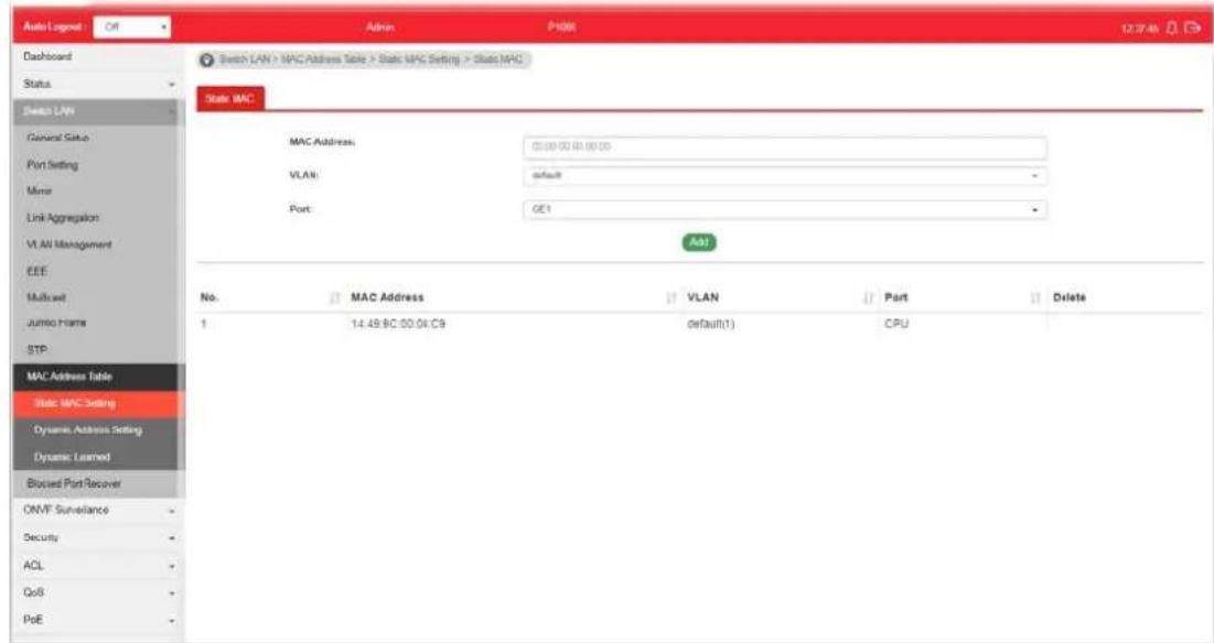
text_image
Auto Log-6 Off Admin P108 12:37:45 Dashboard Status Switch LAN General Set Port Setting Mnse Link Aggregation VLAN Management EEE Multicell Jumper Frame STP MAC Address Table Static MPC Setting Dynamic Address Setting Dynamic Learned Blocked Port Recover ONVF Surveillance Security ACL QoS PoE Switch LAN > MPC Address Table > Static MPC Setting > Static MAC State MAC MAC Address: 00:00:00 00:00:00 VLAN: default - Port: GE1 Add No. MAC Address VLAN Port Delete 1 14:49 BC 00:04 C9 default(1) CPUAvailable settings are explained as follows:
| Item | Description |
| MAC Address | Enter the MAC address that will be forwarded. |
| VLAN | This is the VLAN group to which the MAC address belongs. |
| Port Select the port where | received frame of matched destinationMAC address will be forwarded to. |
| Add | Click it to add any port into the static MAC table. |
| Delete Click it to remove the selected port from the static MAC table. | |
II-10-2 Dynamic Address Setting
This page allows a user to configure aging time for dynamic MAC address.

text_image
Auto Logpost Admin P1685 Dashboard Status Switch LAN General Setup Port Setting Mirror Link Aggregation VLAN Management EEE Multicast Junction frames STP MAC Address Table Static MHC Setting Dynamic Address Setting Dynamic Learned Divided Port Requires OMVP Surveillance Security ACL QoS PuE Switch LAN > MAC Address Table > Dynamic Address Setting > Dynamic Address Setting Dynamic Address Setting Aging Time: X00 (5-12/167) ApplyAvailable settings are explained as follows:
| Item | Description |
| Aging Time Enter the Dynamic MAC address aging out value (5-32767 seconds). | |
| Apply Apply the settings to the switch. | |
II-10-3 Dynamic Learned
This page displays the MAC address and port number automatically learned by VigorSwitch.
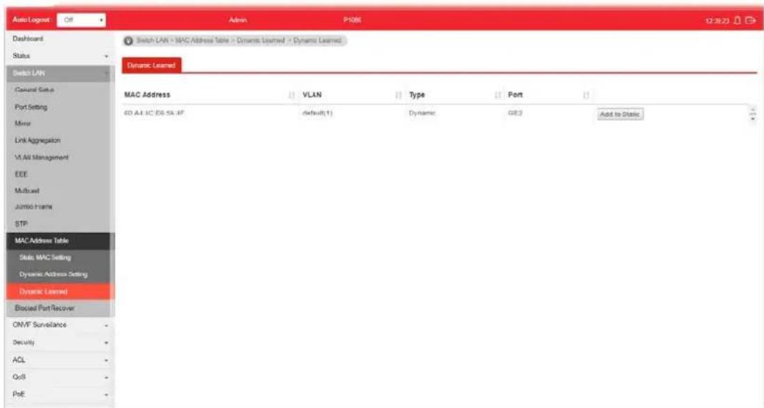
text_image
Auto Logrot Off Admin P106E 12:30:23 Dashboard Status Switch LAN Global Data Port Setting Mirror Link Aggregation VLAN Management EEE Multicast Jumbo frames STP MAC Address Table Static MAC Setting Dynamic Address Setting Dynamic Learned Blocked Port Recover OMVF Surveillance - Security - ACL - QoS - PoE - Switch LAN > MAC Address Table > Dynamic Learned > Dynamic Learned Dynamic Learned MAC Address VLAN Type Port Add to Static SD A4.1C E6-5A.4F default(1) Dynamic GE2Available settings are explained as follows:
| Item | Description |
| MAC Address | Display the MAC address that will be forwarded. |
| VLAN | Display the VLAN group to which the MAC address belongs. |
| Type | Display whether the MAC address is Dynamic (learned by the Switch) or Static Unicast (manually entered in the Static MAC Forwarding screen). |
| Port | Display the port to which this MAC address belongs. |
| Add to Static Click this button to add any port into the static MAC table. | |
II-11 Blocked Port Recover
This page is used for configuring settings to recover the port which is being blocked by the following functions after a defined period of time.
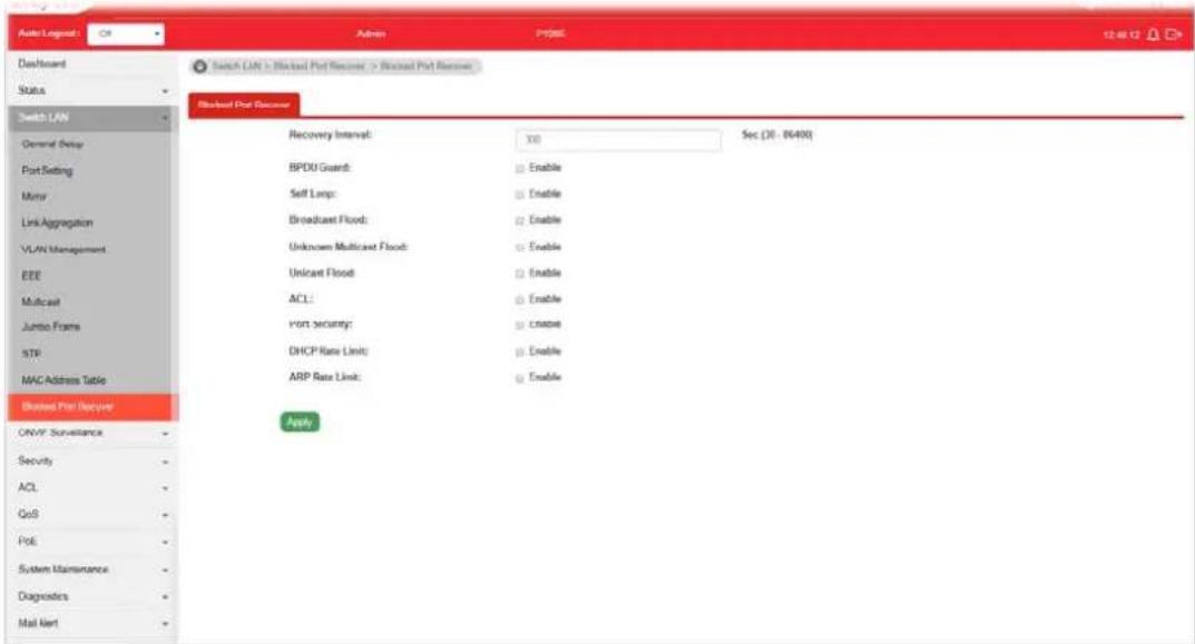
text_image
Auto Logpost: OK Admin Project 12:46:12 Dashboard Status Switch LAN General Delay Port Setting Murry Link Aggregation VLAN Management EEE Multicast Jumbo Frames STR MAC Address Table Blended Port Recovery ONVF Surveillance Security ACL QoS PoE System Maintenance Diagnoders Mail Next Switch LAN > Blocked Port Receiver > Blocked Port Receiver Blocked Port Receiver Recovery Interval: 30 Sec (30 - 86490) BPDU Guard: Enable Self Lamp: Enable Broadcast Flood: Enable Unknown Multicast Flood: Enable Unicast Flood: Enable ACL: Enable Port security: Enable DHCP Rate Limit: Enable ARP Rate Limit: Enable ApplyAvailable settings are explained as follows:
| Item | Description |
| Recovery Interval The port being blocked will be able to receive and send traffic after the time period configured here. | |
| BPDU Guard Enable - Recover the port being blocked by BPDU Guard after the time set in Recovery Interval. | |
| Self Loop Enable - Recover the port being blocked by self loop Guard after the time set in Recovery Interval. | |
| Broadcast Flood Enable - Recover the port being blocked by broadcast flood after the time set in Recovery Interval. | |
| Unknown Multicast Flood Enable - Recover the port being blocked by unknown multicast flood after the time set in Recovery Interval. | |
| Unicast Flood Enable - Recover the port being blocked by unicast flood after the time set in Recovery Interval. | |
| ACL | Enable - Recover the port being blocked by ACL after the time set in Recovery Interval. |
| Port Security Enable - Recover the port being blocked by port security after the time set in Recovery Interval. | |
| DHCP Rate Limit Enable - Recover the port being blocked by DHCP rate limit after the time set in Recovery Interval. | |
| ARP Rate Limit Enable - Recover the port being blocked by ARP rate limit after the time set in Recovery Interval. | |
| Apply Apply the settings to the switch. | |
Part III ONVIF Surveillance
III-1 Topology
ONVIF (Open Network Video Interface Forum), an International standard for current surveillance system industry, focuses on security products based on network IP address.
With this feature, VigorSwitch can:
- Integrate the ONVIF device and surveillance network
● Centralize management of IP video products - View video images directly on VigorSwitch WUI
- Offer remote IP video products maintenance
ONVIF devices can be centralized and managed remotely via VigorSwitch. With a hierarchy view, the administrator can manage several ONVIF devices and check abnormal traffic detected by Vigor system.
III-1-1 Status
The status (including port enabled, traffic, downlink, etc.) of the IP cameras and NVRs (Network Video Recorders) can be seen on this page.

text_image
Auto Logrost 1 mm Dashboard Status Switch LAN CNJF Surveillance Topology Video Device Maintenance Security ACL QoS PoE System Maintenance Diagnostics Mail Alert Product Registration Auto Logrost 1 mm Auto P1085 08:30:43 CNJF Surveillance > Topology > Status Discovery: + Enable ○ Disable Group All Default Username: Auto Info Default Password: Auto Info Active PoE PoE error VSSLS CAM.2 19/100m 100m Status Throughtput Threshold Group Information Total Group 0 +Add New Group Group Name Group Devices Port Modify No data available in table Device InformationAvailable settings are explained as follows:
| Item | Description |
| Discovery | Enable - If enabled, VigorSwitch will automatically detect ONVIF devices, recognize third party IP cameras and NVR and integrate ONVIF device(s) to form surveillance network.Disable - Disable the function of Discovery. |
| Default Username / Default Password | Enter a name / password as the default value.In the entire ONVIF Surveillance menu, VigorSwitch will input this value in advanced and retrieve data. System administrator can access the IP device in which the username and password are as same as the default values.However, you can also input another username/ passwordmanually if the IP device username/ password is different from the one you enter in Default Username/ Default Password. |
| Group Specify a group for | displaying group information and device information under the selected group.Or, choose the default setting, All, to display information for all groups. |
| PoE / PoE Error | PoE - Display the number of LAN PoE device(s) connected to VigorSwitch.PoE Error - Display the number of LAN PoE device(s) disconnected.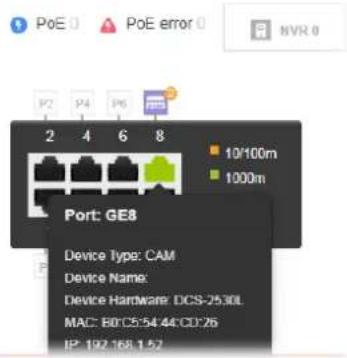 |
| NVR Display the number of | NVR device(s) connected toVigorSwitch. The panel sketch on the screen will display which LAN port that the NVR device connected. |
| CAM | Display the number of IP camera(s) connected to VigorSwitch.The panel sketch on the screen will display which LAN port that the IP camera connected. |
| Group Information | |
| Total Group Display the total number of groups. | |
| +Add New Group A group | can contain one (IP camera or NVR, as group leader) to several devices (IP cameras as group devices).Click the button to create a new group for managing multiple devices.Step (1) - The first page allows you to configure general settings for a new group. |
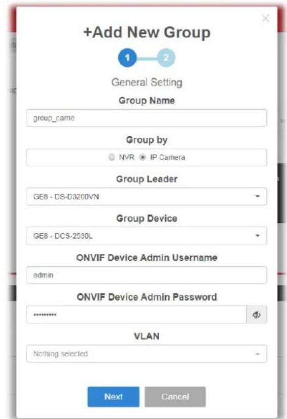
text_image
+Add New Group General Setting Group Name group_came Group by NVR IP Camera Group Leader GE8 - DS-D3200VN Group Device GE8 - DCS-2530L ONVIF Device Admin Username admin ONVIF Device Admin Password .......... VLAN Nothing selected Next Cancel● Group Name - Enter the name of a group.
- Group by - The system will detect the NVR or IP cameras, and list them on the field of NVR or Group Leader.
- NVR/Group Leader - Select an IP device. For the vedio from IP camera will be recorded on an NVR device, it is suggested to assign an NVR as the group leader.
- Group Device - This field lists all devices (IP cameras) not included by other group. Select one IP device to multiple devices or select all the devices for managed by this group.
- ONVIF Device Admin Username/Password - When the group members share the same username and password, enter the username and password in these two field for administration.
● Next - Click it to access into next page.
Step (2) - The second page allows you to configure throughput threshold for the group port. It is helpful for the system administrator to make the corresponding process if encountered abnormal situation.

text_image
+Add New Group 1 2 Group Ports Throughput Threshold Apply to All Member Ports GE8 Ingress Threshold Mailalert Enable Disable GE8 Egress Threshold Mailalert Enable Disable GE8 Ingress Rate (kbps) 16 (16-1000000, multiple of 16) GE8 Egress Rate (kbps) 16 (16-1000000, multiple of 16) OK Cancel- Apply to All Member Ports - Check the box to apply the throughput threshold setting to all member ports.
- GE# Ingress Threshold Mailalert - Click Enable to set the ingress limit value. When the incoming traffic (packet) of the GE port reaches the limit, the Vigor System will send an alert email to the system administrator.
■ GE# Ingress Rate - If enabling the ingress threshold alert, enter the ingress rate as a threshold to send mail alert. - GE# Egress Threshold Mailalert - Click Enable to set the egress limit value. When the outgoing traffic (packet) of the GE port reaches the limit, the Vigor System will send an alert email to the system administrator.
■ GE# Egress Rate - If enabling the egress threshold alert, enter the egress rate as a threshold to send mail alert. - OK - Save the configuration and exit the box.
- Cancel - Exit the box without saving the configuration.
Device Information
| Modify Click it to modify the settings of the selected IP device. |

text_image
Edit Device - Camera Online true Port GE9 Device Name Group No Group Auth Username Auth Info for location modify or device reboot Auth Password Auth Info for location modify or device reboot Location Set Location Settings may not take effect immediately Reboot! OK CancelIII-2-2 Throughput Threshold
This page is used for set throughput threshold for multiple ONVIF devices managed by VigorSwitch.
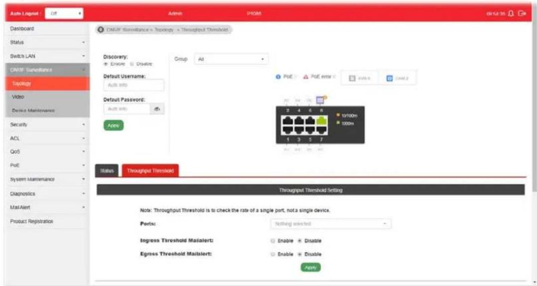
text_image
Auto Lognet Dashboard Status Switch LAN DNMF Surveillance Topology Video Device Maintenance Security ACL QoS PoE System Maintenance Diagnostics Mail Alert Product Registration Auto Lognet Off Admin P1006 DNSF Surveillance > Discovery > Throughput Threshold Discovery: + Enable Disolve Group All Default Username: Auto info Default Password: Auto info Apply PoE PoF error EVMR GAML2 3 4 6 8 10/100m 100m Status Throughput Threshold Throughput Threshold Setting Note: Throughput Threshold is to check the rate of a single port, not a single device. Ports: Setting selected Ingress Threshold MailAlert: Enable Disable Egress Threshold MailAlert: Enable Disable ApplyAvailable settings are explained as follows:
| Item | Description |
| Ports Specify one to several GE ports which will be limited by the threshold configured here. | |
| Ingress Threshold Mailalert | Disable - No mail alert will be sent out.Enable - When the ingress rate reaches the threshold configured here, Vigor system will send alert mail to specified mail address.Ingress Rate (Kbps) - Enter a value as the threshold of ingress packets. |
| Egress Threshold Mailalert | Disable - No mail alert will be sent out.Enable - When the egress rate reaches the threshold configured here, Vigor system will send alert mail to specified mail address.Egress Rate (Kbps)- Enter a value as the threshold of engress packets. |
| Apply Save the settings or changes to the switch. | |
| Modify Click it to modify the settings for the selected GE port / LAG port. | |
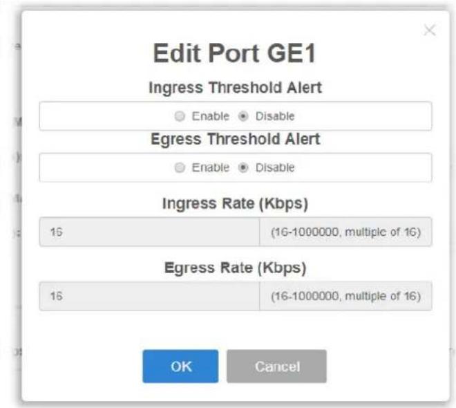
text_image
Edit Port GE1 Ingress Threshold Alert Enable Disable Egress Threshold Alert Enable Disable Ingress Rate (Kbps) 16 (16-1000000, multiple of 16) Egress Rate (Kbps) 16 (16-1000000, multiple of 16) OK CancelIII-2 Video
On this page, users may directly view images captured from the specified IP camera.
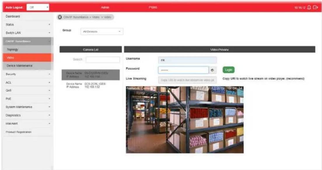
text_image
Auto Logog Dashboard Status Switch LAN OWIF Surveillance Topology Video Device Maintenance Security ACL QoS PoE System Maintenance Diagnostics Mail Alert Product Registration Admin P1300 10:16:12 OWIF Surveillance > Video > Video Group: All Devices Camera List Search: Device factor: DA-CD50M/N (GEN) IP Address: 192.995.194 Device Name: OCS-253XL (GEB) IP Address: 192.168.152 Video Preview Username: enk Password: ****_ Live Streaming: Copy URI to watch live stream on video kit. Login Copy URI to watch live stream on video player (recommend) Network Came 17/12/2019 19:04:34Available settings are explained as follows:
| Item | Description |
| Group | Specify a group which contains the IP camera you want to check. |
| Camera List Search - Enter | the device name of the IP camera for searching and displaying on this field. |
| Video Preview After authenticated with correct username and password, the image of the specified IP camera (supported by VigorSwitch) will be shown immediately. | Username / Password - The default username/ password will be input if it is configured on the Topology page. However, if the default input is not the correct username/ password, enter the correct one of the IP camera instead. |
| Login - Click it to authenticate the username and password for the specified IP camera. | |
| Live Streaming - Display the streaming URI of the IP camera. |
III-3 Device Maintenance
The system administrator can remotely configure time setting and reboot the devices (IP cameras or NVRs) managed by VigorSwitch.
III-3-1 General
This page displays the information (e.g., device online, device name, etc.), time and date and the device action for a selected IP device (e.g., IP camera). Meanwhile, this page allows configuring settings for ping check of IP camera or NVR.

text_image
Auto Logout Off Admin P1985 10:39:46 Dashboard Status Switch LAN CNVF Surveillance Topology Video Device Maintenance Security ACL QoS P-C System Maintenance Diagnostics Mail Alert Product Registration DNVF Surveillance > Device Maintenance > General Device List Search Device Name: DP-2020N (DCE) IP Address: 192.168.1.64 Device Name: DCB-253BL (DCE) IP Address: 192.168.1.52 General Network Security Username admin Password Login Device Information Time and Date Device Online Yes UTC Time Device Name Current Time Manufacturer Time Zone Model Daylight Saving MAC 58.03 FB BF 54 DC Firmware Device Action IP 192.168.1.64 Factory Default ApplAvailable settings are explained as follows:
| Item | Description |
| Device List Search - Enter | a string to search the IP device you want.Usage / Password - The default username/ password will be input if it is configured on the Topology page. However, if the default input is not the correct username/ password, enter the correct one of the IP device instead.Login - Click it to authenticate the username and password.Later, current network settings related to this device will be shown on the screen. |
| Device Information Display | the information related to the selected device.- Click it to modify the device name.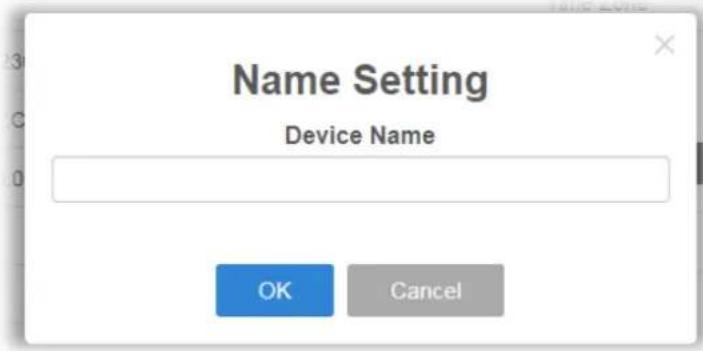 |
| Time and Date Display the | time and date information related to the selected device. - Click it to modify the time setting for the device. |
| Device Action Display the | action performed by IP-based device. Factory Default - Click the Apply button to rest the factory default to the IP device. Reboot - Click the Apply button to reboot the IP device immediately. |
| Device Ping Check -- Configure settings for ping check of IP camera or NVR. | |
| Port Display the port number of the IP device | |
| Enable | Enable - Click it to enable the device ping check function. Disable - Click it to disable the function. |
| Ping IP Address Add Device | - Click it to add an IP address of the device to be pinged by VigorSwitch. Up to 16 IP address(es) can be added and displayed in this field one by one (with the format of x.x.x.x, x.x.x.x, x.x.x.x...) Del Device - Click it to remove the selected IP address. |
| Interval Time (sec) Set a time interval (15, 30, 60, 120) for pinging action. | |
| Retry Time Choose 1, 3, or 5 for Vigor system to retry the pinging action. | |
| Failure Action | Configure the power behavior for each LAN port. Power Cycle - Once the device is offline, VigorSwitch will power off the device and then power on the device again. Power Off - When the device is offline, power off the device immediately. Nothing - When the device is offline, no action will be Power Cycle Power Cycle Power Off Nothing Note: When a PoE hub connecting to LAN port of VigorSwitch, the power behavior (on/off) to the PoE hub also will apply to all the devices connecting to the PoE hub. |
| Mail Alert Enable - When the device is offline, Vigor system will send an alert mail to notify the receptant. Mail with Snapshot - If enabled, the switch will try to get snapshot from the device per half hour. Before using this | |
| feature, set the group authentication information when adding group or configure Default Username/ Password in the Topology page first.Disable- When the device is offline, no action will be performed. | |
| Apply Save the settings or | changes to the switch. |
III-3-2 Network
This page displays the network settings of the specified device (IP CAM or NVR).

text_image
Auto Logout Off Admin P885 11:54:06 Dashboard Status Switch LAN ONVF Surveillance Topology Video Device Maintenance Security ACL QoS PVC System Maintenance Diagnostics Mail Alert Product Registration ONVF Surveillance > Device Maintenance > Network Device List Search Device Name: IP-CCOSV (COS) IP Address: ICD 1991.106 Device Name: DCS-2536, (DCE) IP Address: (0) 168.152 General Network Security Username admin Password Login Mode Static DHCP Hostname: IP Address: Prefix Lengths: Gateways: DNS Servers: DNS Server(s)Available settings are explained as follows:
| Item | Description |
| Device List Search - Enter | a string to search the device you want.Usage / Password - The default username/ password will be input if it is configured on the Topology page. However, if the default input is not the correct username/ password, enter the correct one of the IP device instead.Login - Click it to authenticate the username and password.Later, current network settings related to this device will be shown on the screen. |
| Mode Change the connection | on mode for this device.Static - When it is selected, you have to enter value for network setting manually for the IP device.IP Address - Enter an IPv4 address for the IP devicePrefix Length - Specify the subnet mask for the IP address.Gateway - Enter the IPv4 address for the gateway.DNS Server1/2 - Enter the IP address for primary / secondary DNS server.DHCP - When it is selected, the IP device will be assigned with the settings by the network's DHCP server automatically toaccess the Internet.● Hostname - Display the hostname of the DHCP server. |
| Zero Configuration Enable | - The network settings for the IP device will be configured automatically.Disable - The network settings for the IP devcie must be configured manually. |
| Apply Save the settings or | changes to the switch. |
III-3-3 Security
This page displays the security settings of the specified IP device (IP CAM or NVR).

text_image
Auto Logout: Off Admin P-005 11/06/16 Dashboard Status Switch LAN ONMP Surveillance Topology Video Device Maintenance Security ACL GoS CyE System Maintenance Diagnostics Mail Alert Product Registration ONMP Surveillance > Device Maintenance > Security Device List Search Device Name: OS-CLUO2V6 (OS) IP Address: 182 995.1.94 Device Name: OCIS-2533L (OS) IP Address: 192 168.1.52 General Network Security Username admin Password Login HTTP Ports Enable Disable HTTPS Ports Enable Disable RTSP Ports Enable Disable ApplyAvailable settings are explained as follows:
| Item | Description |
| Device List Search - Enter | a string to search the device you want.Usage / Password - The default username/ password will be input if it is configured on the Topology page. However, if the default input is not the correct username/ password, enter the correct one of the IP device instead.Login - Click it to authenticate the username and password.Later, current network settings related to this device will be shown on the screen. |
| HTTP Ports Current HTTP | port number of the IP device is shown in this field.Enable - Click it to enable the HTTP port configuration and enter a port value if required.Disable - Disable the HTTP port configuration. |
| HTTPS Ports Current HTTPS | port number of the IP device is shown in this field.Enable - Click it to enable the HTTPS port configuration and enter a port value if required.Disable - Disable the HTTPS port configuration. |
| RTSP Ports Current RTSP | port number of the IP device is shown in this field.Enable - Click it to enable the RTSP port configuration and enter a port value if required.Disable - Disable the RTSP port configuration. |
| Apply Save the settings or | changes to the switch. |
Part IV Security
IV-1 Storm Control
Storm Control helps to suppress possible broadcast, unknown multicast or unknown unicast storm by applying a rate limit on those packets.
N-1-1 Properties
This page allows a user to configure general settings for Storm Control.
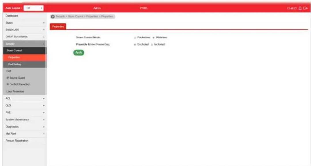
text_image
Auto Logout Off Admin P085 12:46:72 Dashboard Status Switch LAN ONAF Surveillance Security Storm Control Properties Put Setting Dist IP Source Guard IP Conflict Prevention Local Protection ACL QoS PoE System Maintenance Diagnostics Mail Alert Product Registration Security > Storm Control > Properties > Properties Properties Storm Control Mode: Packed/Inte: Kiln/Inte: Preamble & Inter Frame Gap: Excluded Included ApplyAvailable settings are explained as follows:
| Item | Description |
| Storm Control Mode Select | the mode of storm control.● Packet/sec - Storm control rate will be calculated by packet-based.● Kbits/sec - Storm control rate will be calculated by octet-based. |
| Preamble & Inter Frame Gap | Select the rate calculation with/ without preamble & IFG (20 bytes).● Excluded - Exclude preamble & IFG (20 bytes) when count ingress storm control rate.● Included - Include preamble & IFG (20 bytes) when count ingress storm control rate. |
| Apply Apply the settings to the switch. | |
IV-1-2 Port Setting
This page allows the network administrator to configure port settings for Storm Control. The configuration result for each port will be displayed on the table listed on the lower side of this web page.
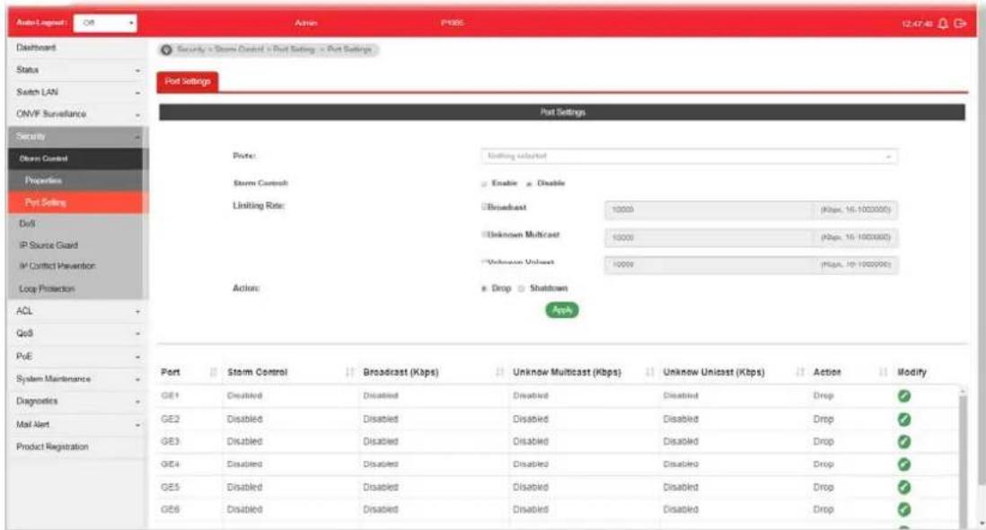
text_image
Auto-Layout OS Admin PHBS 12:47:40 Dashboard Status Switch LAN ONVF Surveillance Security Storm Control Properties Port Setting DoS IP Source Guard IP Control Prevention Loop Protection ACL QoS PUE System Maintenance Diagnostics Mail Alert Product Registration Security - Storm Control - Port Setting - Port Settings Port Settings Port: Storm Control Limiting Rate: Actions: Estimating selected Enable Enable Broadcast 10000 (Kbps, 16-1000000) Unknown Multicast 10000 (Kbps, 16-1000000) Unknown Unicast 10000 (Kbps, 16-1000000) Drop Shutdown Apply Port Storm Control Broadcast (Kbps) Unknow Multicast (Kbps) Unknow Unicast (Kbps) Action Modify GE1 Disabled Disabled Disabled Disabled Drop GE2 Disabled Disabled Disabled Disabled Drop GE3 Disabled Disabled Disabled Disabled Drop GE4 Disabled Disabled Disabled Disabled Drop GE5 Disabled Disabled Disabled Disabled Drop GE6 Disabled Disabled Disabled DisabledAvailable settings are explained as follows:
| Item | Description |
| Ports | Use the drop down list to select the port profile (GE1 to GE8). |
| Storm Control | Disable- Disable the storm control configuration for the selected port profile.Enable- Enable the storm control configuration for the selected port profile. |
| Limiting Rate Check the box(es) to enable strom control rate limited for Broadcast, Unknown Multicast and/or Unknown Unicast packet.Broadcast- Specify the storm control rate for Broadcast packet. Value of storm control rate, Unit: Kbps (Kbits per-second). The range is from 16 to 1000000.Unknown Multicast- Specify the storm control rate for unknown multicast packet. Value of storm control rate, Unit: Kbps (Kbits per-second). The range is from 16 to 1000000.Unknown Unicast- Specify the storm control rate for unknown multicast packet. Value of storm control rate, Unit: Kbps (Kbits per-second). The range is from 16 to 1000000. | |
| Action Select the state of setting.Drop- Packets exceed storm control rate will be dropped.Shutdown- Port exceeds storm control rate will be shutdown. | |
| Apply Apply the settings to the switch. | |
IV-2 DoS
A Denial of Service (DoS) attack is a hacker attempt to make a device unavailable to its users. DoS attacks saturate the device with external communication requests, so that it cannot respond to legitimate traffic. These attacks usually lead to a device CPU overload.
The DoS protection feature is a set of predefined rules that protect the network from malicious attacks. The DoS Security Suite Setting enables activating the security suite.
IV-2-1 Properties
This page allows a user to configure DoS setting to enable/disable DoS function for global setting.

text_image
Auto Lognet Dashboard Status Switch LAN OMF Surveillance Security > DoS + Properties > Properties Properties Global Settings Dat MAC - Src MAC LAND UDP Bat TCP Bit Ping of Death IPV4 Max Fragrances ICMP Fragrances IPv4 Ping Max Size IPv6 Ping Max Size Ping Max Size Setting Smart Attack TCP Min Hbl Size TCP-SYN (SPORTx1024) Null Scan Attack X-mass Scan Attack TCP SYN-3IN Attack TCP SYN-RST Attack Enable Disable Enable Disable Enable Disable Enable Disable Enable Disable Enable Disable Enable Disable Enable Disable Enable Disable Enable Disable Enable Disable Enable Disable Enable Disable Enable Disable Enable Disable Enable Disable Enable Disable Enable Disable Enable Disable Enable Disable Enable Disable Enable Disable Enable Disable Enable Disable Enable Disable Enable Enable Enable Enable Enable Enable Enable Enable Enable Enable Enable Enable Enable Enable Enable Enable Enable Enable Enable Enable Enable Enable Enable Enable Enable Enable Enable Enable Enable Enable Enable Enable Enable Enable Enable Enable Enable Enable Enable Enable Enable Enable Enable Enable Enable Enable Enable Enable Enable Enable Enable DisableAvailable settings are explained as follows:
| Item | Description |
| Dst MAC=Src MAC Drop the packets if the destination MAC address is equal to the source MAC address.● Disabled - Disable the item function.● Enabled - Enable the item function. | |
| LAND Drop the packets if the source IP address is equal to the destination IP address.● Disabled - Disable the item function.● Enabled - Enable the item function. | |
| UDP Blat Drop the packets if the UDP source port equals to the UDP destination port.● Disabled - Disable the item function.● Enabled - Enable the item function. | |
| TCP Blat Drop the packages if the TCP source port is equal to the TCP destination port.● Disabled - Disable the item function. | |
| ● Enabled - Enable the item function. | |
| Ping of Death Avoid ping of death attack.Ping packets that length are larger than 65535 bytes.● Disabled - Disable the item function.● Enabled - Enable the item function. | |
| IPv6 Min Fragments Check the minimum size of IPv6 fragments, and drop the packets smaller than the minimum size. The valid range is from 0 to 65535 bytes, and default value is 1240 bytes.● Disabled - Disable the item function.● Enabled - Enable the item function. | |
| ICMP Fragments Drop the fragmented ICMP packets.● Disabled - Disable the item function.● Enabled - Enable the item function. | |
| IPv4 Ping Max Size Determine the IPv4 PING packet with the length.● Disabled - Disable the item function.● Enabled - Enable the item function.- | |
| IPv6 Ping Max Size Determine the IPv6 PING packet with the length.● Disabled - Disable the item function.● Enabled - Enable the item function. | |
| Ping Max Size Setting Determine the IPv4/ IPv6 PING packet with the length. Specify the maximum size of the ICMPv4/ ICMPv6 ping packets. The valid range is from 0 to 65535 bytes, and the default value is 512 bytes. | |
| Smurf Attack | Avoid smurf attack. The length range of the netmask is from 0 to 323 bytes, and default length is 0 byte.● Disabled - Disable the item function.● Enabled - Enable the item function. |
| TCP Min Hdr Size Check the minimum TCP header and drops the TCP packets with the header smaller than the minimum size. The length range is from 0 to 31 bytes, and default length is 20 bytes.● Disabled - Disable the item function.● Enabled - Enable the item function. | |
| TCP-SYN (SPORT<1024) Drop SYN packets with sport less than 1024.● Disabled - Disable the item function.● Enabled - Enable the item function. | |
| Null Scan Attack Drop the packets with NULL scan.● Disabled - Disable the item function.● Enabled - Enable the item function. | |
| X-mas Scan Attack Drop the packets if the sequence number is zero, and the FIN, URG and PSH bits are set.● Disabled - Disable the item function.● Enabled - Enable the item function. | |
| TCP SYN-FIN Attack Drop the packets with SYN and FIN bits set.● Disabled - Disable the item function.● Enabled - Enable the item function.- | |
| TCP SYN-RST Attack Drop the packets with SYN and RST bits set.● Disabled - Disable the item function. | |
| TCP Fragment (Offset=1) | Drop the fragmented ICMP packets.● Disabled - Disable the item function.● Enabled - Enable the item function. |
| Apply Apply the settings to the switch. | |
IV-2-2 DoS Port Setting
This page allows a user to configure and display the state of DoS protection for interfaces. The configuration result for each port will be displayed on the table listed on the lower side of this web page.
text_image
Auto Logpost Off Admin P385 12:50:26 Dashboard Status Switch LAN ONVF Surveillance Security Storm Control DoS Properties DoS Port Setting IP Source Guard IP Conflict Prevention Lock Protection ACL QoS PoE System Maintenance Diagnostics Mail Alert Product Registration Security > DoS > DoS PortSetting > Port Settings Port Settings Port Setting Ports: Nothing selected DoS Protection: Enable Disable Ferry Port Port Protection Modify GE1 Disabled GE2 Disabled GE3 Disabled GE4 Disabled GE5 Disabled GE6 Disabled GE7 Disabled GE8 DisabledAvailable settings are explained as follows:
| Item | Description |
| Port | Use the drop down list to select the port profile (GE1 to GE8) or profiles. |
| DoS Protection | ● Disabled - Disable the function of DoS Protection. ● Enabled - Enable the function of DoS Protection. |
| Apply Apply the settings to the switch. | |
| Modify | - Click it to modify the port settings. |
IV-3 IP Source Guard
By using the source IP address filtering function, IP source guard can prevent a malicious host from feigning a legal host with its IP address and performing malicious attack.
N-3-1 Port Settings
IP source guard is a port-based feature. Therefore, it is necessary to configure detailed settings for each GE/LAG port interface separately.

text_image
Auto Logged OS Admin P000 12.52.52 Dashboard Status Switch LAN ONVF Surveillance Security Storm Control Disk IP Source Guard Port Settings MPV Binding IP Conflict Prevention Log Protection Port Settings Port: Nothing selected Name: Enable Verify Source: IP IP MAC Max Entry: 0 (0 - 50) default (0, 0 is Unlimited) Port State Verify Source Current Entry Max Entry GE1 Disabled IP 0 Unlimited GE2 Disabled IP 0 Unlimited GE3 Disabled IP 0 Unlimited GE4 Disabled IP 0 Unlimited GE5 Disabled IP 0 Unlimited GE6 Disabled IP 0 Unlimited GE7 Disabled IP 0 Unlimited GE8 Disabled IP 0 Unlimited LA31 Disabled IP 0 Unlimited LA32 Disabled IP 0 UnlimitedAvailable settings are explained as follows:
| Item | Description |
| Ports | Use the drop down list to select the port (GE1 to GE8, LAG1 to LAG8) or ports for applying IP source guard function. |
| State | Enable - Check it to make the port(s) selected above apply the settings configured in this page. |
| Verify Source Specify the type of source IP for the packet coming from.IP - Only the packet with specified IP address will be verified.IP-MAC - Only the packet with specified IP address and MAC address will be verified. | |
| Max Entry Define the number (0~50) for the port.The default is 0 (no limit). | |
| Apply Apply the settings to the switch. | |
IV-3-2 IMPV Binding
This page allows the network administrator to set the filtering conditions (binding type, MAC address, IPv4 address) for packets through the specified LAN port.
text_image
Auto Logpost: Off Admin: P385 12:54:46 Dashboard Status Switch LAN OM/F Surveillance Security Storm Control DuS IP Source Guard Port Settings MPV Binding IP Contact Prevention Lock Protection ACL QoS PuE System Maintenance Diagnostics Mail Alert Product Registration IP-MAC/Port-VLAN Binding Table Ports: DE1 VLAN: (1-40%) Binding: + IP-MAC Port-VLAN + IP Port-VLAN MAC Address: (0100000000000) Out Address: 1 Adj Port VLAN MAC Address IP Address Subnet Mask Binding Type Edit GE1 10 00:50.10.17.1F.29 192.168.1.45 255.255.255.250 IP-MAC Port-VLAN Static EditAvailable settings are explained as follows:
| Item | Description |
| Ports | Use the drop down list to select the port (GE1 to GE8, LAG1 to LAG8) or ports for applying IMPV Binding function. |
| VLAN | Choose a number as VLAN ID which is easy to be identified for a packet containing with it.It is optional setting. |
| Binding Select the binding | type for such feature.IP-MAC-Port-VLAN-Packets will be allowed to pass through the port interface if they meet the conditions specified by IP address, MAC address, Port setting and VLAN ID setting.IP-Port-VLAN-Packets will be allowed to pass through the port interface if they meet the conditions specified by IP address, Port setting and VLAN ID setting. |
| MAC Address Enter the MAC | address of the device connecting to the port interface selected above. |
| IPv4 Address Enter the IP | address with mask address of the device connecting to the port interface selected above. |
| Add Click it to create a new binding profile. | |
| Edit | - Click it to modify the settings for the selected entry. |
text_image
Edit Ports: GE2 VLAN: 20 (1 - 4094) Binding: IP-MAC-Port-VLAN IP-Port-VLAN MAC Address: 00:50.7C:12.00.FF IPv4 Address: 192.168.1.56 / 255.255.255.255 OK Cancel
click it to remove the selected entry.
IV-4 IP Conflict Prevention
A user can configure IP addresses for network devices manually. However, it might result in conflict between different devices due to using the same IP address, and cause the devices not working correctly.
This page allows you to prevent IP conflict by binding the port with the specified IP address.
text_image
Auto Logpost: Off Admin P085 12:57:30 Dashboard Status Switch LAN ONMP Surveillance Security Storm Control DoS IP Source Guard IP Conflict Prevention Loop Protection ACL QoA PoE System Maintenance Diagnostics Mail Next Product Registration IP Conflict Prevention IP Conflict Prevention setup Wizard: Check Next Wizard IP Prevention: Enable Disable Link Aggregation: Enable Disable Conflict Status Host Type DHCP Client Static Binding DHCP Server Multi Host With DHCP Server Protected Host Table Port IP Address MAC Address Host Type Conflict Ports Modify GE1 192.168.1.56 (Static) DHCP Server IPAvailable settings are explained as follows:
| Item | Description |
| IP Prevention | Enable - Click it to activate the function of IP prevention.Disable - Click it to deactivate the function of IP prevention. |
IP Conflict Prevention Setup Wizard
Quick Start Wizard - The system will guide to bind server port with an IP address step by step.
Step 1
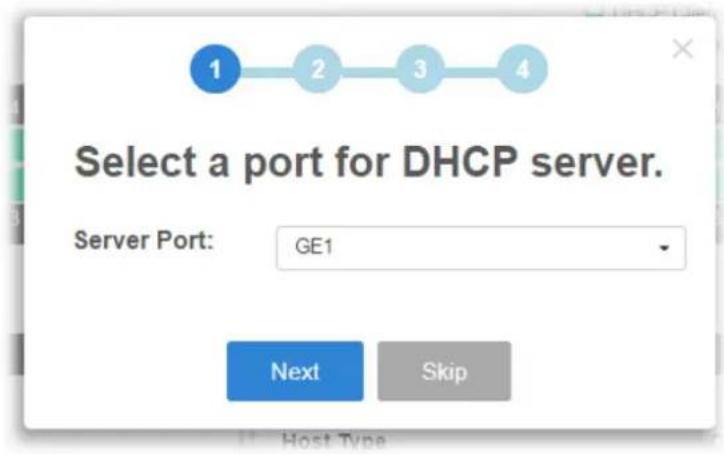
text_image
Select a port for DHCP server. Server Port: GE1 Next SkipStep 2
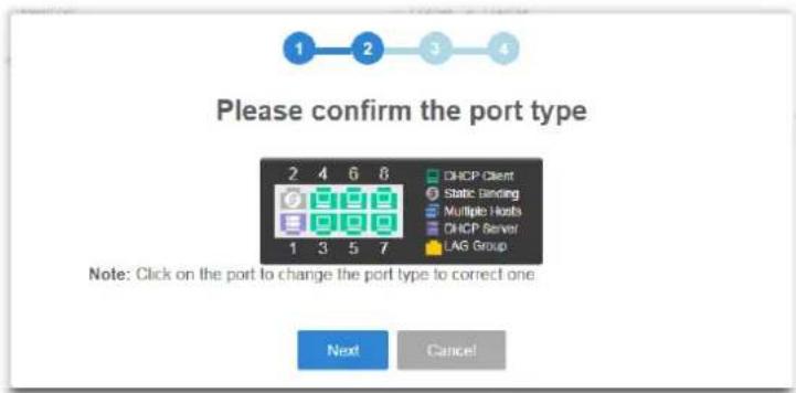
text_image
Please confirm the port type 2 4 6 8 DHCP Client Static Binding Multiple Hosts DHCP Server LAG Group Note: Click on the port to change the port type to correct one. Next Cancel
text_image
Detecting your network...Step 3
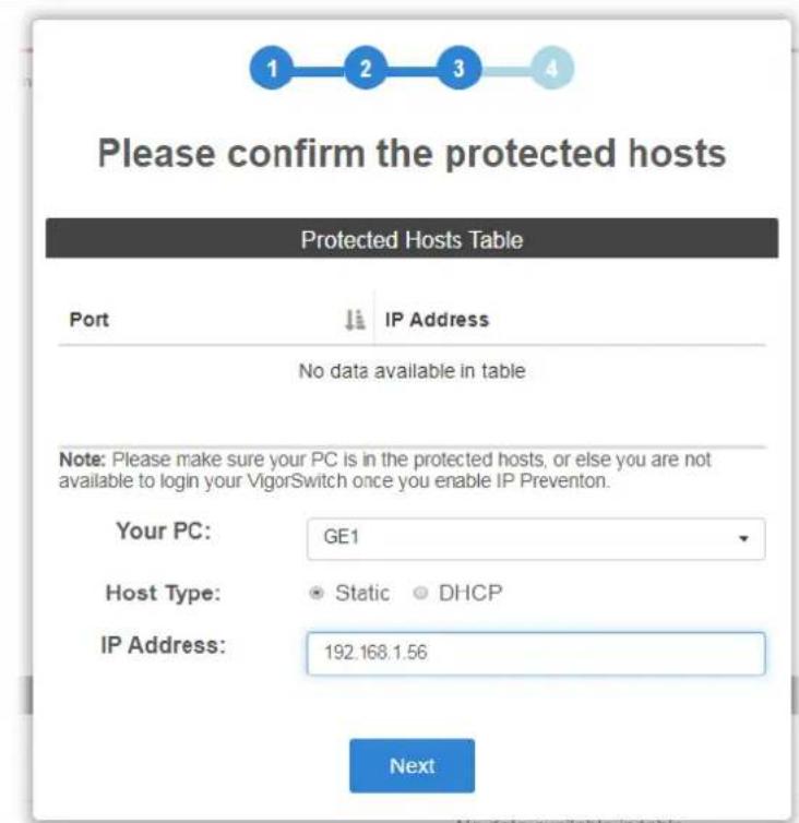
text_image
Please confirm the protected hosts Protected Hosts Table Port IP Address No data available in table Note: Please make sure your PC is in the protected hosts, or else you are not available to login your VigorSwitch once you enable IP Prevention. Your PC: GE1 Host Type: Static DHCP IP Address: 192.168.1.56 NextStep 4

text_image
IP Conflict Prevention • Enable ○ Disable OKAfter clicking OK, the IP address specified for the GE port will be unavailable for other network devices.
| Apply Apply the settings to the switch. | |
| Clear Remove all settings of IP source guard DHCP snooping and dynamic ARP inspection. | |
| Modify | - Click it to modify the settings for the selected entry. |
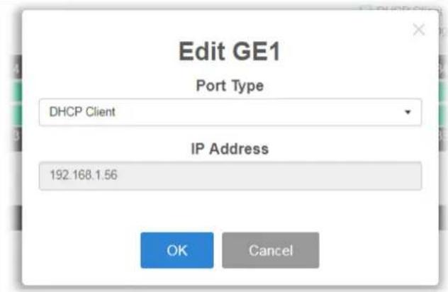
text_image
Edit GE1 Port Type DHCP Client IP Address 192.168.1.56 OK Cancel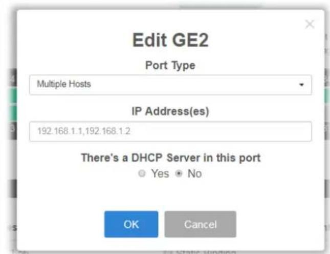
text_image
Edit GE2 Port Type Multiple Hosts IP Address(es) 192.168.1.1,192.168.1.2 There's a DHCP Server in this port Yes No OK CancelPort Type - There are four selections - DHCP Client, Static Binding, Multiple Hosts and DHCP Server. Each type will bring out different IP address(es) settings.
OK - Click it to save the settings.

- Click it to remove the selected entry.
IV-5 Loop Protection
Loop event might be caused due to wrong hardware connection. VigorSwitch will periodically send packets out to check if they loopback or not. This page allows you to set conditions and perform an action when VigorSwitch detects the looped packet.
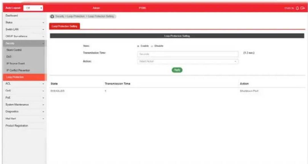
text_image
Auto Logset Off Admin P065 13825 Dashboard Status - Switch LAN - OMMF Sur-abance - Security - Storm Control - DoS - IP Source Guard - IP Conflict Prevention - Loop Protection ACL - OnS - PoE - System Maintenance - Diagnostics - Mail Net - Product Registration Security > Loop Protection > Loop Protection Setting Loop Protection Setting Loop Protection Setting State: Enable Exclude Transmission Time: Seconds (1.3 sec.) Actions: Select Action Apply State Transmission Time Action DISABLED 1 Shutdown PortAvailable settings are explained as follows:
| Item | Description |
| State | Enable- VigorSwitch detects the loop event of GE ports/ LAG ports automatically.Disable- VigorSwitch will not detect the loop event. |
| Transmission Time When the loop event occurred, VigorSwitch will perform the action after a period of time. | |
| Action When the switch detects loop situation occurred to a port; it will perform the action selected in this field.Select ActionLogShutdown PortShutdown Port and LogLog- The switch will record such event as a log.Shutdown Port- The switch will shut down the port.Shutdown Port and Log- The switch will shut down the port and record the event as a log. The system administrator will view the content from system log. | |
| Apply Apply the settings to the switch. | |
This page is left blank.
Part V ACL Configuration
V-1 Create ACL
An Access Control List (ACL) is a sequential list of permit or deny conditions that apply to IP addresses, MAC addresses, or other more specific criteria. This switch tests ingress packets against the conditions in an ACL one by one. A packet will be accepted as soon as it matches a permit rule, or dropped as soon as it matches a deny rule. If no rules match, the frame is accepted.
V-1-1 MAC
The function is used to show the Access Control List (ACL) based on Layer 2 filtering, the MAC layer. The ACL is composed by many Access Control Element (ACE) rules. You can create a new ACL here; then add multiple ACEs.

text_image
Auto Layout Off Admin PDB5 13:02:46 Dashboard Status Switch LAN ON/IF Surveillance Security ACL Create ACL Create ACE ACL Binding QoS PoE System Maintenance Diagnostics Mail Alert Product Registration ACL > Cross ACL > MAC MAC IPM IPG ACL Profile Name: ACL_IAC Add No. NAC ACL Name Action 1 ACL_IAC BAvailable settings are explained as follows:
| Item | Description |
| ACL Profile Name Enter a | name for creating a new ACL profile. |
| Add Add a new ACL entry using given ACL name. | |
| Action |  - click it to remove the selected entry. - click it to remove the selected entry. |
V-1-2 IPv4
The function is used to show the Access Control List (ACL) based on Layer 2 to Layer 4 filtering, the IPv4. The ACL is composed by many Access Control Element (ACE) rules. You may create a new ACL here; then add multiple ACEs.
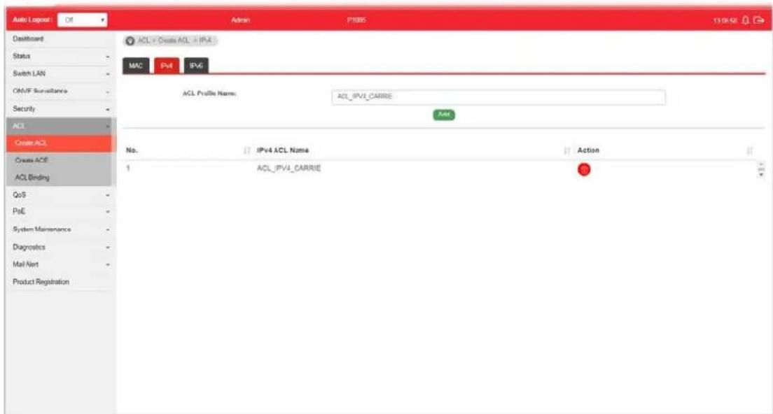
text_image
Auto Logpost Off Admin P1885 132658 Dashboard Status Switch LAN CM/F Surveillance Security ACL Create ACL Create ACE ACL Binding QoS PoE System Maintenance Diagnostics Mail Net Product Registration ACL > Create ACL > IP-4 MAC Pull IP-6 ACL Profile Name: ACL_IPVI_CARRIE Add No. IPv4 ACL Name Action 1 ACL_IPVI_CARRIE 0Available settings are explained as follows:
| Item | Description |
| ACL Profile Name Enter a | name for creating a new ACL profile. |
| Add Add a new ACL entry using given ACL name. | |
| Action |  - click it to remove the selected entry. - click it to remove the selected entry. |
V-1-3 IPv6
The function is used to show the Access Control List (ACL) based on Layer 2 to Layer 4 filtering, the IPv6. The ACL is composed by many Access Control Element (ACE) rules. You may create a new ACL here; then add multiple ACEs.
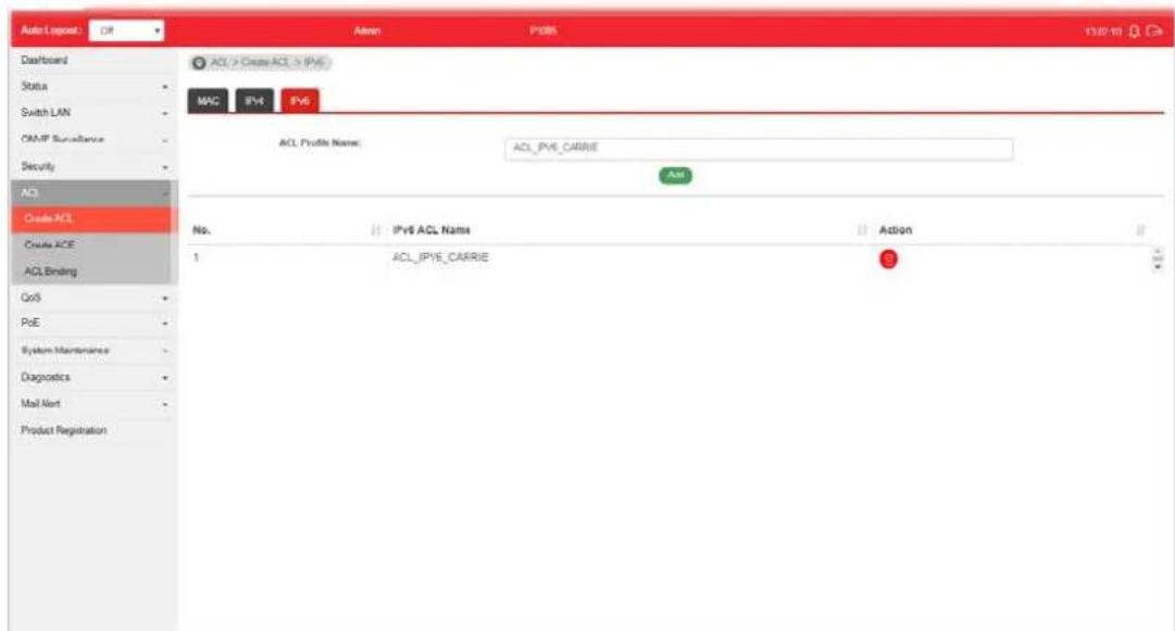
text_image
Auto1 Repeat Off Admin P085 13/07/19 Dashboard Status Switch LAN COMP Surveillance Security ACI Create ACL Create ACE ACL Binding QoS PoE System Maintenance Diagnostics Mail Alert Product Registration ACL > Create ACL > IPv6 MAC IPv4 IPv6 ACL Profile Name: ACL_IPV6_CARRIER Add No. IPv6 ACL Name Action 1 ACL_IPV6_CARRIER 3Available settings are explained as follows:
| Item | Description |
| ACL Profile Name Enter a | name for creating a new ACL profile. |
| Add Add a new ACL entry using given ACL name. | |
| Action | - click it to remove the selected entry. |
V-2 Create ACE
Since ACL based on MAC, IPv4 and/or IPv4 has been created on the section of IV-1, now you can add multiple ACE rules for each ACL.
V-2-1 MAC
This page shows ACE based on MAC address. You may choose ACL, permit, and deny particular packet or frame, even shutdown the port.
You may provide filtering/matching criteria for one or more of packet characteristic (such as Source/Destination MAC, Ethertype, VLAN, 802.1p) for this ACE to identify the packet.
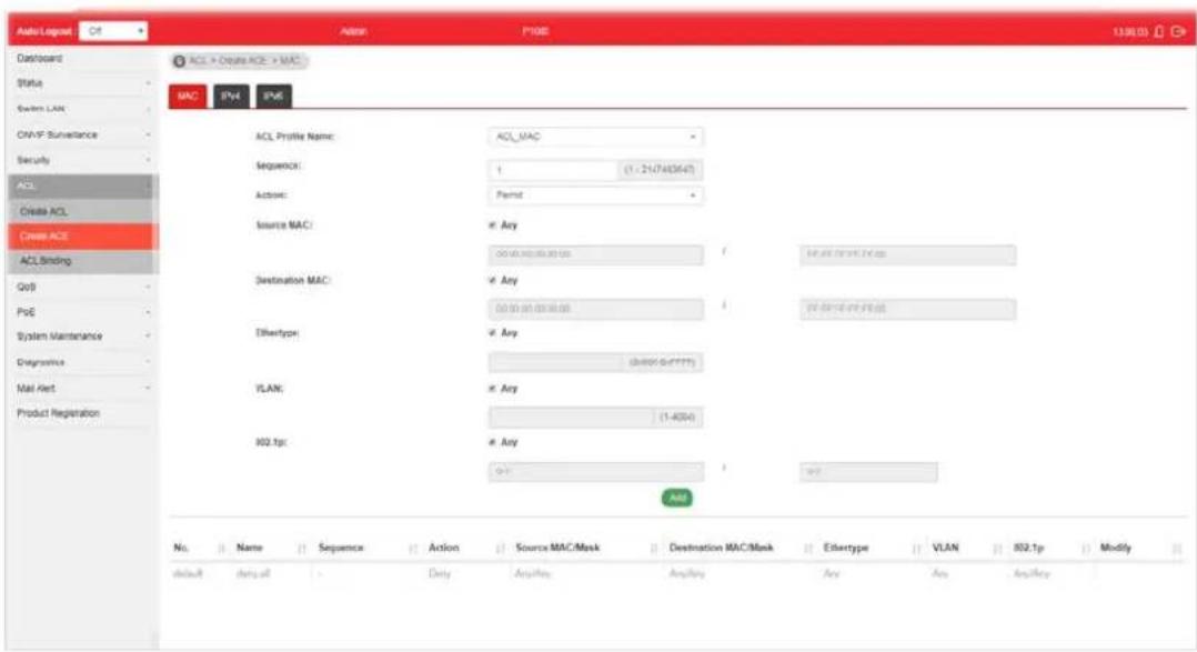
text_image
AutoLegend Ctrl Dashboard Status System LAN CMA/F Surveillance Security ACL Create ACL Create ACE ACL Binding Go0 PoE System Maintenance Diagnosis Mail Alert Product Registration MAC PV4 PV6 ACL Profile Name: ACL_MAC Sequence: 1 (1 - 21/7/403647) Actions: Format Source MAC: Any Destination MAC: Any Ethertype: Any VLAN: Any 102.1pc: Any Add No. Name Sequence Action Source MAC/Mask Destination MAC/Mask Ethertype VLAN 802.1p Modify default data-all Only Aux/Res Aux/Res Any Any Aux/ResAvailable settings are explained as follows:
| Item | Description |
| ACL Profile Name Use the | drop down list to selected one of the user defined ACL profiles. |
| Sequence | Assign a sequence number to this ACE. The sequence is used to identify which one of ACEs in an ACL is firstly used to match ingress packets. The switch port bound with an ACL use the contained ACE rules, start with the one with lower sequence number to match the packet first. |
| Action Select the action applied to the packet matched this ACE. Permit or deny the packets into switch core, or shutdown the port for stopping further transmission.● Permit● Deny● Shutdown | |
| Source MAC / Destination MAC | Specify the source and the destination MAC address for filtering.Any - All packets will be filtered.Or, enter the IP address to filter the packets coming from that address. |
| Ethertype Specify ethernet | type for filtering.Select Any.Or, enter the value with the format of “0x600 ~ 0xFFFF”. |
| VLAN Specify VLAN profile | for filtering.Select Any.Or, enter a VLAN number. The packets coming from the VLAN specified here will be filtered by Vigor device. |
| 802.1p Specify the 802.1p | priority value for filtering. Select Any, or a number from 0 to 7. |
| Add Click it to create a new ACE rule. | |
| Modify | [6y7c]- click it to modify the settings for the selected entry.[5z6w]- click it to remove the selected entry. |
V-2-2 IPv4
This page shows ACE based on IPv4 address. You may choose ACL, permit, and deny particular packet or frame, even shutdown the port.
You may provide filtering/ matching criteria for one or more of following packet characteristic (such as Protocol over the IP layer, Source/ Destination IPv4 address, Type of Service, Source/ Destination port number, TCP flags, ICMP Type, if chosen protocol contains ICMP), for this ACE to identify the packet.

text_image
Auto Lognet C6 Admin P108 139926 Dashboard Status Switch LAN ONVP Surveillance Security ACL Create ACL Create ACE ACL Binding QoB PoE System Maintenance Diagnosis Mail Alert Product Registration ACL Profile Name: ACL_PV4_CARRIE Sequence: 1 (1 - 217453643) Action: Permit Protocol: Any Source IP: Any Destination IP: Any Service: Any Source Port: Any Destination Port: Any CMP Type: Any CMP code: Any 0.010 205.210.210.0 205.210.210.0 ABS No. | Name | Sequence | Action | Protocol | Source IP/Mask | Destination L... | OSCP | IPP | Source Port ... | Source Port ... | Destination P... | Destination P... | TCP Flag | default story off Copy Any Amplicay Amplicay Any Any Any Any Any Any AnyAvailable settings are explained as follows:
| Item | Description |
| ACL Profile Name Use the | drop down list to selected one of the user defined ACL profiles. |
| Sequence | Assign a sequence number to this ACE. The sequence is used toidentify which one of ACEs in an ACL is firstly used to match ingress packets. The switch port bound with an ACL use the contained ACE rules, start with the one with lower sequence number to match the packet first. |
| Action Select the action applied to the packet matched this ACE. Permit or deny the packets into switch core, or shutdown the port for stopping further transmission.● Permit● Deny● Shutdown | |
| Protocol Specify the protocol for filtering.● Any - All packets will be filtered.● Select - Choose one of the protocol (e.g., ICMP, IP in IP, TCP, EGP, IGP...) from the drop down list. Packets passing through the selected protocol will be filtered.● Define - Specify a type number (0 - 255) for ICMP code. For example, 0 means “Echo Reply”; 254 means “RFC3692-style Experiment 2”. | |
| Source IP / Destination IP | Specify the source and the destination IPv4 address for filtering.Any - All packets will be filtered.Or, enter the IP address to filter the packets coming from that address. |
| Service | ● Any - All packets will be filtered.● DSCP - All IP traffic is mapped to queues based on the DSCP field in the IP header. If traffic is not IP traffic, it is mapped to the lowest priority queue.● IP Precedence - All IP traffic is mapped to queues based on the IP Precedence field in the IP header. If traffic is not IP traffic, it is mapped to the lowest priority queue. |
| Source Port / Destination Port | Specify the source and destination port number for filtering the packets.● Any - All packets will be filtered.● Single - Only the packets passing through the number defined here will be filtered.● Range - Only the packets passing through the port range defined here will be filtered. |
| ICMP Type | ● Any - All packets will be filtered.● Select - Choose one of the type (e.g., Destination Unreachable Echo Reply, MLD Query....) from the drop down list.● Define - Specify a type number (0 - 255) for ICMP code. For example, 0 means “Echo Reply”; 254 means “RFC3692-style Experiment 2”. |
| ICMP code Each ICMP type | can be defined with different codes. For example, if you define ICMP Type as “3”, then the available codes for Type 3 will be 0-15.Any - All packets will be filtered.Or, enter 0 to 255 based on the ICMP type specified. |
| Add Click it to create a new binding profile. | |
| Modify | - click it to modify the settings for the selected entry. - click it to remove the selected entry. |
V-2-3 IPv6
This page allows the network administrator to create ACE based on IPv6 address.
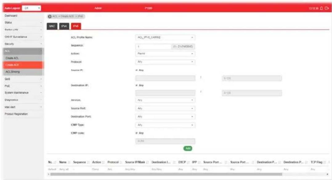
text_image
Auto Loglog ACL × Create ACE × IPv6 MAC IPv4 IPv6 ACL Profile Name: ACL_IPV8_CARRIE Sequence: 1 (1-21/7455643) Actions: Pipe Protocol:Any Source IP: Any Destination IP: Any Service: Any Source Import: Any Destination Port: Any ICMP Type: Any ICMP Code: Any A&E No. Name Sequence Action Protocol Source IP/Mask Destination L... DSCP IPP Source Port... Source Port... Destination P... Destination P... TCP Flag Default:Amy all Camp Any Accuracy Any/Bay Any Amy Buy Any Amy AnyAvailable settings are explained as follows:
| Item | Description |
| ACL Profile Name Use the | drop down list to selected one of the user defined ACL profiles. |
| Sequence | Assign a sequence number to this ACE. The sequence is used to identify which one of ACEs in an ACL is firstly used to match ingress packets. The switch port bound with an ACL use the contained ACE rules, start with the one with lower sequence number to match the packet first. |
| Action Select the action applied to the packet matched this ACE. Permit or deny the packets into switch core, or shutdown the port for stopping further transmission.● Permit● Deny● Shutdown | |
| Protocol Specify the protocol for filtering.● Any - All packets will be filtered.● Select - Choose one of the protocol (e.g., ICMP, TCP, EGP...) from the drop down list. Packets passing through the selected protocol will be filtered.● Define - Specify a type number (0 - 255) for ICMP code. For example, 0 means “Echo Reply”; 254 means “RFC3692-style Experiment 2”. | |
| Source IP / Destination IP | Specify the source and the destination IPv6 address for filtering.Any - All packets will be filtered.Or, enter the IPv6 address to filter the packets coming from that address. |
| Service | Any - All packets will be filtered.DSCP - All IP traffic is mapped to queues based on the DSCP field in the IP header. If traffic is not IP traffic, it is mapped to the lowest priority queue.IP Precedence - All IP traffic is mapped to queues based on the IP Precedence field in the IP header. If traffic is not IP traffic, it is mapped to the lowest priority queue. |
| Source Port / Destination Port | Specify the source and destination port number for filtering the packets.Any - All packets will be filtered.Single - Only the packets passing through the number defined here will be filtered.Range - Only the packets passing through the port range defined here will be filtered. |
| ICMP Type | Any - All packets will be filtered.Select - Choose one of the type (e.g., Destination Unreachable Echo Reply, MLD Query....) from the drop down list.Define - Specify a type number (0 - 255) for ICMP code. For example, 0 means “Echo Reply”; 254 means “RFC3692-style Experiment 2”. |
| ICMP code Each ICMP type | can be defined with different codes. For example, if you define ICMP Type as “3”, then the available codes for Type 3 will be 0-15.Any - All packets will be filtered.Or, enter 0 to 255 based on the ICMP type specified. |
| Add Click it to create a new binding profile. | |
| Modify |  - Click it to modify the settings for the selected profile. - Click it to modify the settings for the selected profile. - Click it to remove the selected entry. - Click it to remove the selected entry. |
V-3 ACL Binding
This section allows you to bind Access Control Lists created in previous section to an interface (physical port or aggregation).
A physical port can only be bound with one of the IPv4 and IPv6 ACL, not both.

text_image
Auto Lognet Ctrl Dashboard Status System LAN CMA/F Surveillance Security ACL Create ACL Create ACE ACL Binding QoS PoE System Maintenance Diagnosis Mail card Product Registration Admin P1000 ACL × ACL Binding × ACL Breaks ACL Binding Ports MAC ACL: IPv4 ACL: IPv6 ACL: Working selected: Select MAC ACL: Select IPv4 ACL: Select IPv6 ACL: ADDV Port MJC ACL IPv4 ACL IPv6 ACLAvailable settings are explained as follows:
| Item | Description |
| Ports Use the drop down list to select the port profiles (GE1 to GE8) for binding ACL. | |
| MAC ACL / IPv4 ACL / IPv6 ACL | Select ACLs (MAC, IPv4, and/ or IPv6) to be bound on this interface (port), so Switch may filter packets by using it. |
| Apply Apply the settings to the switch. | |
Part VI QoS Configuration
VI-1 General
QoS (Quality of Service) functions to provide different quality of service for various network applications and requirements and optimize the bandwidth resource distribution so as to provide a network service experience of a better quality.
VI-1-1 Properties
VI-1-1-1 QoS General Setting
This page allows the network administrator to specify Ingress Trust Mode for basic QoS mode.
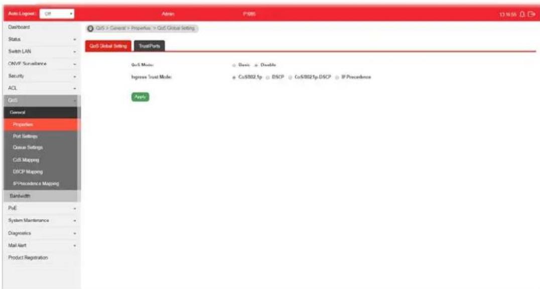
text_image
Auto Logout: Off Admin: P-085 13.16.15 Overboard Status Switch LAN ONVIF Surveillance Security ACL QoS General Properties Port Settings Docus Settings CoS Mapping DISCP Mapping IP Precedence Mapping Bandwidth PoE System Maintenance Diagnostics Mail Alert Product Registration QoS > General > Properties > QoS Global Setting QoS Global Setting TrustParts QoS Motor : Basis Double Bypass Trust Mode : Co002.1p DISCP Co0021p DISCP IP Precedence ApplyAvailable settings are explained as follows:
| Item | Description |
| QoS Mode Disable -Disable | the function of QoS mode.Basic - Enable the function of QoS mode. |
| Ingress Trust Mode Select | the QoS operation mode.CoS/802.1p -Traffic is mapped to queues based on the CoS field in the VLAN tag, or based on the per-port default CoS value if there is no VLAN tag on the incoming packet.DSCP - All IP traffic is mapped to queues based on the DSCP field in the IP header. If traffic is not IP traffic, it is mapped to the lowest priority queue.CoS/802.1p-DSCP - All IP traffic is mapped to queues based on the DSCP field in the IP header. If traffic is not IP but has VLAN tag, mapped to queues based on the CoS value in the VLAN tag.IP Precedence - All IP traffic is mapped to queues based on the DSCP field in the IP header. If traffic is not IP but has VLAN tag, mapped to queues based on the CoS value in the VLAN tag. |
Apply Apply the settings to the switch.
VI-1-1-2 Trust Ports
This page allows the network administrator to enable the trust mode of basic QoS on each port. Port that is trust disabled will be sent with lowest priority queue. The configuration result for each port will be displayed on the table listed on the lower side of this web page.
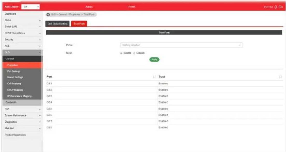
text_image
Auto Logpost Dashboard Status Switch LAN ONMP Surveillance Security ACL Ctrl General Properties Port Settings Queue Settings Cell Mapping DISCP Mapping IP Precedence Mapping Bandwidth Port GE1 GE2 GE3 GE4 GE5 GE6 GE7 GE8 Gulf > General + Properties > Trust Ports Gulf Global Setting Trust Ports Test Ports Ports: Nothing selected Trust: + Enable 0 Disable Apply Port GT1 GT2 GT3 GT4 GT5 GT6 GT7 GT8 GT9 GT10 GT11 GT12 GT13 GT14 GT15 GT16 GT17 GT18 GT19 GT20 GT21 GT22 GT23 GT24 GT25 GT26 GT27 GT28 GT29 GT30 GT31 GT32 GT33 GT34 GT35 GT36 GT37 GT38 GT39 GT40 GT41 GT42 GT43 GT44 GT45 GT46 GT47 GT48 GT49 GT50 GT51 GT52 GT53 GT54 GT55 GT56 GT57 GT58 GT59 GT60 GT61 GT62 GT63 GT64 GT65 GT66 GT67 GT68 GT69 GT70 GT71 GT72 GT73 GT74 GT75 GT76 GT77 GT78 GT79 GT80Available settings are explained as follows:
| Item | Description |
| Ports | Use the drop down list to select the port profile (GE1 to GE8) or profiles. |
| Trust | Click Enable to make traffic follow the trust mode in general setting.● Enable - Traffic will follow trust mode in general setting.● Disable - No QoS service for this port. |
| Apply Apply the settings to the switch. | |
VI-1-2 Port Settings
This page allows the network administrator to configure port settings for QoS. The configuration result for each port will be displayed on the table listed on the lower side of this web page.
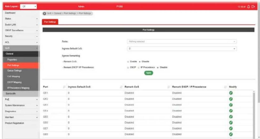
text_image
Auto Logos: Of Admin P1066 13:10:41 Dashboard Status Switch LAN ONVF Surveillance Security ACL QoS General Properties Port Settings Queue Settings Cell Mapping DISCP Mapping IP Precedence Mapping Port Settings Port: Nothing selected Ingress Default CoS: 0 Egress Remarking - Remark CoS: Disable - Disable - Remark DISCP/IP Precedence - DISCP - IP Precedence - Disable N=0 Port Ingress Default CoS Remark CoS Remark DISCP/IP Precedence Modify GE1 0 Disabled Disabled ✓ GE2 0 Disabled Disabled ✓ GE3 0 Disabled Disabled ✓ GE4 0 Disabled Disabled ✓ GE5 0 Disabled Disabled ✓ GE6 0 Disabled Disabled ✓ GE7 0 Disabled Disabled ✓ GE8 0 Disabled Disabled ✓Available settings are explained as follows:
| Item | Description |
| Ports Use the drop down list to select the port profile. | |
| Ingress Default CoS | Specify the default CoS priority value for those ingress frames without given trust QoS tag (802.1q/ DSCP/ IP Precedence, depending on configuration). |
| Engress Remarking | |
| Remark CoS | Disable - Disable CoS remarking function for outgoing packets.Enable - Egress traffic will be marked with CoS value according to the Queue to CoS mapping table. |
| Remark DSCP/IP Precedence | Disable - Disable DSCP/ IP Precedence remarking function for outgoing packets.DSCP - Egress traffic will be marked with DSCP value according to the Queue to DSCP mapping table.IP Precedence - Egress traffic will be marked with IP Precedence value according to the Queue to IP Precedence mapping table. |
| Apply Apply the settings to the switch. | |
| Modify | Click it to modify the settings for the selected port profile. |
VI-1-3 Queue Settings
VigorSwitch supports multiple queues for each interface. The higher numbered queue represents the higher priority. The following lists the types of supported priority queue:
- Strict Priority (SP) - Egress traffic from the higher priority queue will be transmitted first, lower priority queue shall wait until all traffic in SP queue is transmitted.
● Weighted Round Robin (WRR) - The number of packets sent from the queue is proportional to the weight of the queue.
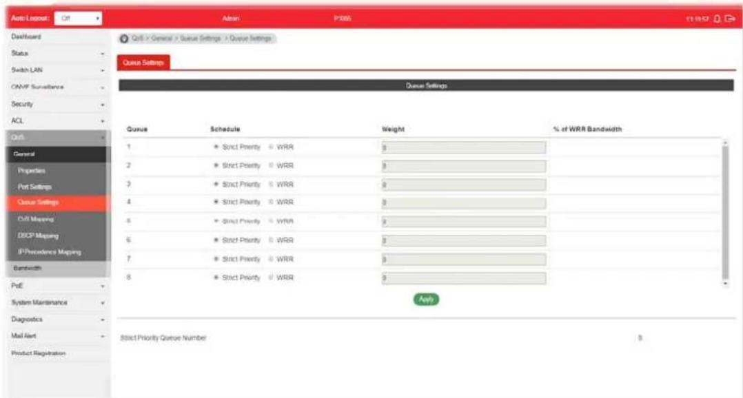
text_image
Auto Logpost Off Admin P365 01:00:27 Dashboard Status Switch LAN CNMF Surveillance Security ACL QoS General Properties Port Settings Queue Settings C#B Mapping DCSP Mapping IP/Precedence Mapping Bandwidth PoE System Maintenance Diagnostics Mail Alert Product Registration QoS > General > Queue Settings > Queue Settings Queue Settings Queue Settings Queue Schedule Weight % of WRR Bandwidth 1 Strict Priority WRR 0 2 Strict Priority WRR 0 3 Strict Priority WRR 0 4 Strict Priority WRR 0 5 Strict Priority WRR 0 6 Strict Priority WRR 0 7 Strict Priority WRR 0 8 Strict Priority WRR 0 Apply Strict Priority Queue Number $Available settings are explained as follows:
| Item | Description |
| Queue There are eight queue ID numbers allowed to be configured. | |
| Schedule | ● Strict Priority - Click it to set queue to strict priority type.● WRR - Click it to set queue to Weight round robin type. |
| Weight If the queue type is WRR, set the queue weight for the queue. | |
| % of WRR Bandwidth Display the percentage of traffic which can be sent by current queue compared to total WRR queues. | |
| Apply Apply the settings to the switch. | |
| Strict Priority Queue Number | Display the number of queues using Strict Priority method. |
VI-1-4 CoS Mapping
This section allows user to configure how ingress frames with CoS/802.1p tag map to QoS queues, and QoS queues to CoS/802.1p on egress frames.
Actual effectiveness is based on how QoS is configured in previous QoS section. This page provides settings for user to configure mapping only.

text_image
Auto/Export Dashboard Status Switch LAN CAMF Surveillance Security ACL Call General Properties Put Settings Queue Settings Call Mapping DISCP Mapping IP Precedence Mapping Bandwidth PUE System Maintenance Diagnostics Mail Alert Product Registration Auto / Export Action PS865 13:30:41 Call > General > Call Mapping > Call Mapping Call Mapping Call to Queue Mapping (for ingress) Class of Service Queue 0 2 * 1 1 * 2 2 * 3 4 * 4 5 * ? 9 * 6 7 * 7 Queue to Call Mapping (for Egress Remapping) Queue Class of Service 1 1 * 2 0 * 3 2 * 4 3 * 5 4 * 6 5 * 7 0 * 8 7Available settings are explained as follows:
| Item | Description |
| CoS to Queue Mapping (for Ingress) - Settings for incoming packets. | |
| Class of Service Display the class of service value (0 to 7). | |
| Queue | Define the queue ID (level 1 to 8) for different class of service values. |
| Queue to CoS Mapping (for Egress Remarking) - Settings for outgoing packets. | |
| Queue | Display the queue ID (level 1 to 8) for different class of service values. |
| Class of Service Define the class of service value (0 to 7). | |
| Apply Apply the settings to the switch. | |
VI-1-5 DSCP Mapping
This section allows user to configure how ingress packets with DSCP tag map to QoS queues, and QoS queues to DSCP on egress packets.
Actual effectiveness is based on how QoS is configured in previous QoS section. This page provides settings for user to configure mapping only.
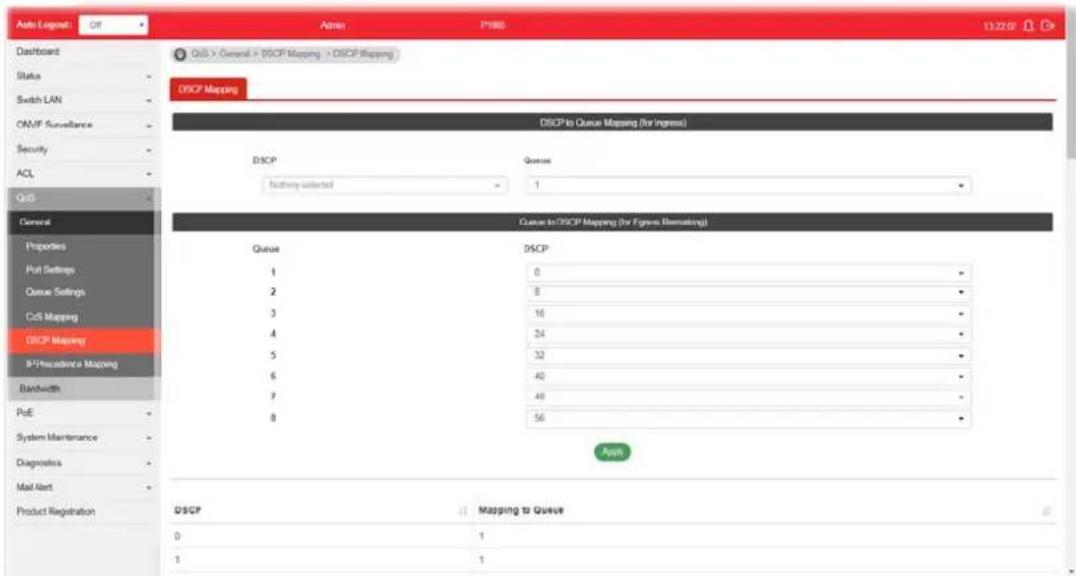
text_image
Auto Logen: Off Admin: P1985 13.22 OF Dashboard Status Switch LAN CAN/F Surveillance Security ACL QoS General Properties Put Settings Queue Settings CsS Mapping DSCP Mapping R²/Recaidence Mapping Bandwidth PoE System Maintenance Diagnostics Mail Alert Product Registration QoS > General > DSCP Mapping > DSCP Mapping DSCP Mapping DSCP to Queue Mapping (for ingress) DSCP Queue: Nothing selected 1 Queue to DSCP Mapping (for frame Remapping) Queue DSCP 1 0 - 2 8 - 3 16 - 4 34 - 5 32 - 6 40 - 7 48 - 8 56 - App DSCP Mapping to Queue 0 1 1 1Available settings are explained as follows:
| Item | Description |
| DSCP to Queue Mapping (for Ingress) - Settings for the incoming packets. | |
| DSCP Display the DSCP value (0 to 7). | |
| Queue Define the queue ID (level 1 to 8) for different DSCP values. | |
| Queue to DSCP Mapping (for Egress Remarking) - Settings for outgoing packets. | |
| Queue Display the queue ID (level 1 to 8) for different DSCP values. | |
| DSCP Define the DSCP value (0 to 7). | |
| Apply Apply the settings to the switch. | |
This section allows user to configure how ingress packets with IP Precedence tag map to QoS queues, and QoS queues to IP Precedence on egress packets.
Actual effectiveness is based on how QoS is configured in previous QoS section. This page provides settings for user to configure mapping only.

text_image
Screenshot of a network security interface showing IP precedence and queue mapping settings for a system involving QoS, Security, and ACL.Available settings are explained as follows:
| Item | Description |
| IP Precedence to Queue Mapping (for Ingress) - Settings for the incoming packets. | |
| IP Precedence Display the | IP Precedence value (0 to 7). |
| Queue Define the queue ID | (level 1 to 8) for different IP Precedence values. |
| Queue to IP Precedence Mapping (for Egress Remarking) - Settings for outgoing packets. | |
| Queue Display the queue ID | (level 1 to 8) for different IP Precedence values. |
| IP Precedence Define the | IP Precedence value (0 to 7). |
| Apply Apply the settings to the switch. | |
VI-2 Bandwidth
Use the bandwidth setting pages to define values that determine how much traffic the switch can receive and send on specific port or queue.
VI-2-1 Ingress Rate Limit
This page allows a user to configure ingress port rate limit. The ingress rate limit is the number of bits per second that can be received from the ingress interface. Excess bandwidth above this limit is discarded. The configuration result for each port will be displayed on the table listed on the lower side of this web page.
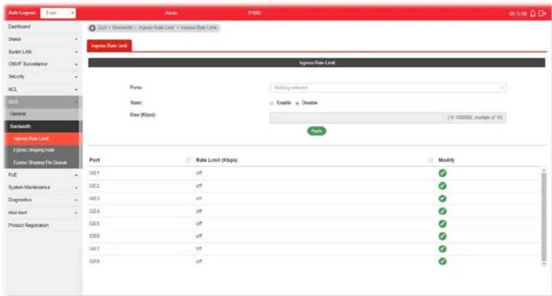
text_image
Auto Layout: 3 min Dashboard Status Switch LAN ONVF Surveillance Security ACL QoS General Bandwidth Ingress Rate Limit Ingress Mapping Rate Express Shaping Fee Queue Port Rate Limit (Kbps) Port: Nothing selected State: Enable Disable Rate (Kbps): 15-1000002 multiple of 16 Modify Port Rate Limit (Kbps) Port: Rate Limit (Kbps) ModifyAvailable settings are explained as follows:
| Item | Description |
| Ingress Rate Limit | |
| Ports | Use the drop down list to select the port profile (GE1 to GE8) or profiles. |
| State | ● Disable - Disable ingress bandwidth control.● Enable - Enable ingress bandwidth control. |
| Rate (Kbps) Enter the rate | value,<16-1000000>,unit:16 Kbps. |
| Apply Apply the settings to the switch. | |
| Modify | - Click it to modify the settings for the selected port profile. |
VI-2-2 Egress Shaping Rate
This page allows a user to configure egress port rate limit. The egress rate limit is the number of bits per second that can be received from the egress interface. Excess bandwidth above this limit is discarded.

text_image
Auto Logpost 3 ns Dashboard Status Switch LAN OMAF Surveillance Security ACL QoR General Bandwidth Ingress Rate Limit Express Shaping Rate Express Shaping Rate Port GIR (Kbps) Port: Nothing selected State: Enable Disable CR (Kbps) (1%-100000), multiple of 10 Ports Modify PoE GE1 off ✓ System Maintenance GE2 off ✓ Diagnostics GE3 off ✓ Mail Alert GE4 off ✓ Product Registration GE5 off ✓ GE6 off ✓ GE7 off ✓ GE8 off ✓Available settings are explained as follows:
| Item | Description |
| Egress Shapping Rate | |
| Ports | Use the drop down list to select the port profile (GE1 to GE8) or profiles. |
| State | Disable - Disable egress bandwidth control.Enable - Enable egress bandwidth control. |
| CIR (Kbps) Enter the rate value,<16-1000000>,unit:16 Kbps. | |
| Apply Apply the settings to the switch. | |
| Modify | Click it to modify the settings for the selected port profile. |
VI-2-3 Egress Shaping Per Queue
This page allows user to configure the maximum egress bandwidth not only by port but also by specific QoS queues. The configuration result for each port will be displayed on the table listed on the lower side of this web page.
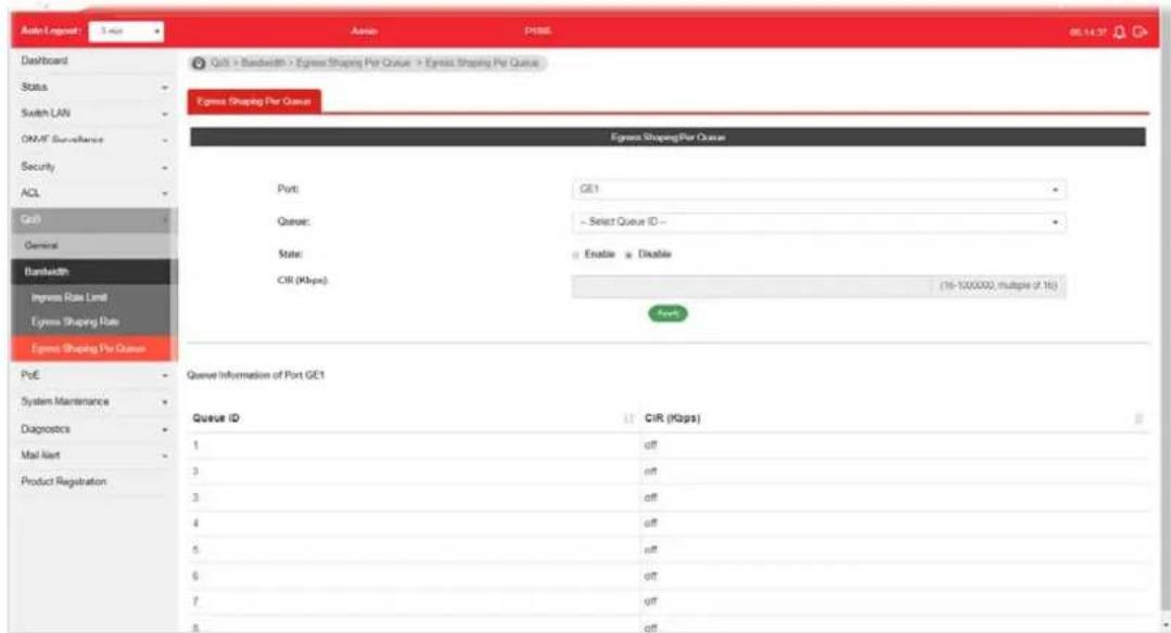
text_image
Aidn Logpost: 5 sec Dashboard Status Switch LAN ON/AF Security Security ACL Grid General Bandwidth Ingress Rate Limit Egress Shaping Rate Egress Shaping Per Queue QoE > Bandwidth > Express Shaping Per Queue > Egress Shaping Per Queue Egress Shaping Per Queue Egress ShapingPer Queue Port: GE1 Queue: Select Queue ID State: Enable Disable CIR (Kbps) (16-100,000), multiple of 16s Port Queue Information of Port GE1 Queue ID CIR (Kbps) 1 off 3 off 3 off 4 off 5 off 6 off 7 off 8 offAvailable settings are explained as follows:
| Item | Description |
| Egress Shapping Per Queue | |
| Port | Use the drop down list to select the port profile (GE1 to GE8) or profiles. |
| Queue Use the drop down | list to select queue number (1 to 8) for the selected GE port. |
| State | ● Disable - Disable egress bandwidth control. ● Enable - Enable egress bandwidth control. |
| CIR (Kbps) Enter the rate value, <16-1000000>, unit: 16 Kbps. | |
| Apply Apply the settings to the switch. | |
This page is left blank.
Part VII PoE Configuration
VII-1 Properties
This page allows a user to configure general settings for PoE and configure priority of each port for supplying PoE power. While maximum power budget is reached, power will be served starting with critical priority.
If the priority setting for all GE ports is configured as the same value (e.g., High); then, GE1 will have the highest priority to obtain PoE power in actual operation.
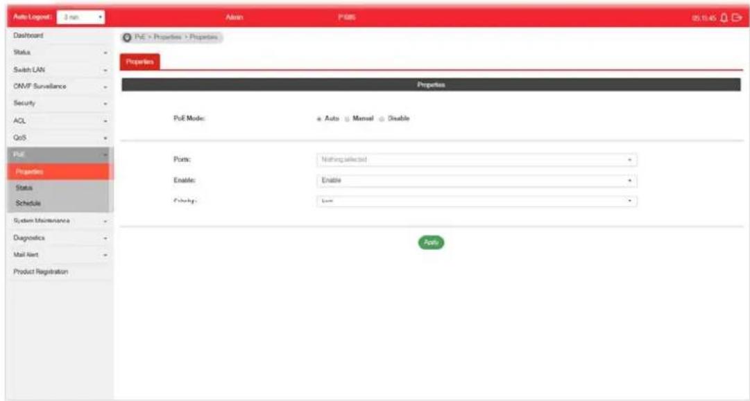
text_image
Auto Logout: 3 min Dashboard Status Switch LAN CAMP Surveillance Security ACL QoS PUE Properties Status Schedule System Maintenance Diagnostics Mail Alert Product Registration Auto P685 05.10.45 PUE > Properties > Properties Properties Properties PUE Mode: ● Auto ▼ Manual ● Enable Ports: Nothing selected Enable: Enable Checking: None PortsAvailable settings are explained as follows:
| Item | Description |
| PoE Mode | Disable- Disable the PoE function.Auto- Provides plug and play PoE function. PoE schedule and Power Limit are disabled in this mode.Manual- Before using PoE>>Schedule, set Manual as PoE mode. |
| Ports Use the drop down list to select the port (GE1 to GE8) or ports for applying PoE configuration. | |
| Enable | Enable- Make the selected ports be applied with PoE mode.Disable- Make the selected ports be not applied with PoE mode. |
| Priority Select Priority for | PoE device.Low-Set PoE device to low priority connection.High-Set PoE device to high priority connection.Critical- Set PoE device to highest priority connection. |
| Power Limit | This setting is available whenManualis selected as PoE Mode.Enter the value as the maximum limit of power given to each physical port. |
| Apply Apply the settings to the switch. | |
VII-2 Status
This page displays the current PoE status (configured in Properties, Device Check and Schedule) for each PoE port.
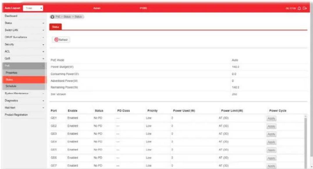
text_image
Auto Lognet: 3 mm Dashboard Status Switch LAN OM/F Surveillance Security ACL GoS Port Properties Status Schedule System Maintenance Diagnostics Mail Alert Product Registration PVE - Status - Status Status Refresh Port Mode Power Budget(W) Consuming Power(V) Advertised Power(W) Remaining Power(W) SW Version Auto 140.0 0.0 0 140.0 250 Port Enable Status PD Class Priority Power Used (W) Power Limit(W) Power Cycle GE1 Enabled No PD — Low 0 AT (30) Apply GE2 Enabled No PD — Low 0 AT (30) Apply GE3 Enabled No PD — Low 0 AT (30) Apply GE4 Enabled No PD — Low 0 AT (30) Apply GE5 Enabled No PD — Low 0 AT (30) Apply GE6 Enabled No PD — Low 0 AT (30) Apply GE7 Enabled No PD — Low 0 AT (30) ApplyAvailable settings are explained as follows:
| Item | Description |
| Refresh Click it to refresh | the status page. |
| PoE Mode | Display the PoE Mode (Manual, Auto or Disable) selected for the LAN port. |
| Power Budget(W) Display | the maximum power this switch can supply over PoE. |
| Consuming Power(W) Display | play current power being consumed by all devices over PoE. |
| Remaining Power(W) Display | play remaining power that can be supplied to additional devices over PoE. |
| Power Cycle | Apply – If PoE device connects to VigorSwitch, such button will be available for you to manually perform the cold boot for the PoE device by cycling the power supply. |
VII-3 Schedule
VII-3-1 Schedule Profile
This page allows the network administrator to configure maximum 15 PoE schedule rules.
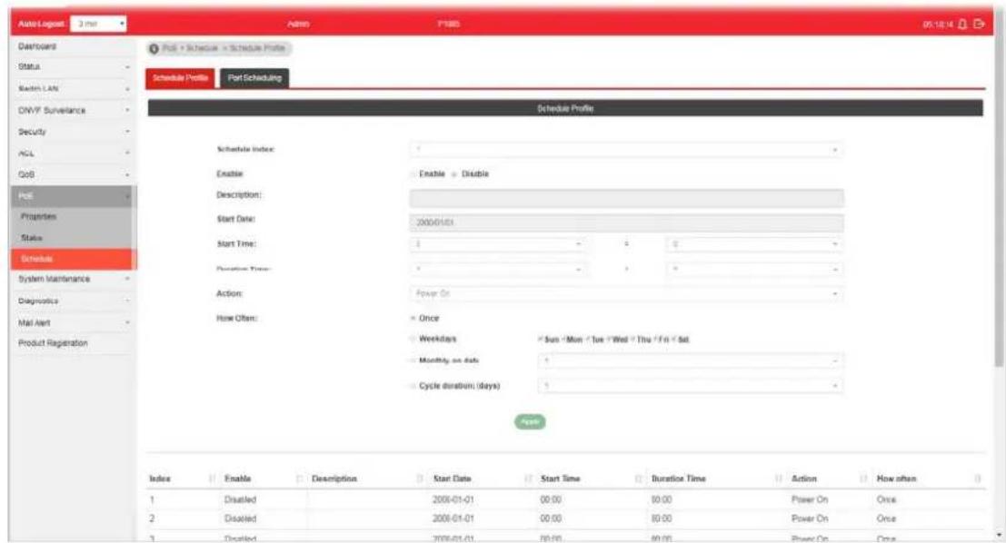
text_image
Schedule Profile Part Scheduling Schedule Profile Schedule Index: Enable Description: Start Date: Start Time: Duration Time: Action: How Often: Once Weekdays Sun / Mon / Tue / Wed / Thu / Fri / Sat Monthly on date: Cycle duration (days) Index Enable Description Start Date Start Time Duration Time Action How often 1 Disabled 2006-01-01 00:00 00:00 Power On Once 2 Disabled 2006-01-01 00:00 00:00 Power On Once 3 Disabled 2006-01-01 00:00 00:00 Power On OnceAvailable settings are explained as follows:
| Item | Description |
| Schedule Index | Use the drop down list (1 to 15) to choose one schedule profile. |
| Enable | Disable - The selected schedule profile will not take action but be saved for future use.Enable - The selected schedule profile will take action as configured. |
| Description Enter a brief comment for such schedule. | |
| Start Date | Specify the starting date of the schedule by choosing from a drop down calendar. |
| Start Time Specify the starting time of the schedule by using the drop down list to specify the starting time (hours and minutes). | |
| Duration Time Define the time duration (hours and minutes). | |
| Action Specify which action should perform during the period of the schedule.Power On - PoE connection is always on.Power Off - PoE connection is always down. | |
| How Often Specify how often the schedule will be applied.Once - The schedule will be applied just once.Weekdays - Specify which days in one week should perform the schedule.Monthly, on date - Specify the day in a month as the | |
| starting point.● Cycle duration (days) - The period of cycle duration is between 1 day and 31 days. For example, 7 means the whole cycle is 7 days; 20 means the whole cycle is 20 days. When the time is up, the PoE device will be turned on of off automatically. | |
| Apply Apply the settings to the switch. | |
VII-3-2 Port Scheduling
This page allows the network administrator to specify the PoE port for applying the schedule. The configuration result for each port will be displayed on the table listed on the lower side of this web page.
Note that the schedule profile is only available in PoE Manual mode.

text_image
Auto Logged Off Admin P#08 06:00 Dashboard FVC > Schedule > Port Scheduling Schedule Profile Port Scheduling Port Scheduling Ports: GE1 Schedule Index: 1 Apply System Maintenance GE1 None Diagnostics GE2 None Mail Alert GE3 None Product Registration GE4 None GE5 None GE6 None GE7 None GE8 NoneAvailable settings are explained as follows:
| Item | Description |
| Ports Select the port or ports for applying the schedule. | |
| Schedule Index Use the drop down list to choose the schedule profile (from 1 to 15). After clickingApply, the selected port(s) will be applied with the specified schedule. | |
| Apply Apply the settings to the switch. | |
This page is left blank.
Part VIII System Maintenance
This page allows a user to configure TR-069 settings for connecting to VigorACS 2.

text_image
Auto Logout Off Address P180 05.25.04 Dashboard Status Switch LAN ONVF Surveillance Security ACL QoS Post System Maintenance TSL 000 Open/PIN Wethrock LLDP SNAP Access Manager Time and Date Backup Manager Upgrade Manager Account Manager Factory Default Reboot Switch Diagnostics System Maintenance > TSL-000 > TSL-003 Setting TSL-009 Setting ACS Settings TSL No: Accessible < Enable URL: Enter URL Wizard Username: Enter User Name Password: Enter Password Last Inform: (NA) Test Inform: Test With Inform CPE Settings CRE Client: HTTP > HTTPS URL: https://192.168.1.224.806.htm/CRN.html Port: 8093 0 - 69836 Username: ugr Password: TLS Version Settings TLS Minimum Protocol Version: = TL 51.2 TL 51.3 Periodic Inflow SettingsAvailable settings are explained as follows:
| Item | Description |
| ACS Settings | TR-069 - Click Enable to activate the settings on this page.URL - The URL must be entered according to the ACS (Auto Configuration Server) you want to link.Wizard - Click it to enter the IP address of VigorACS server, port number and the handler.Usage - The string of username must be entered according to the VigorACS (Auto Configuration Server) you want to link.Password - The password must be entered according to the VigorACS (Auto Configuration Server) you want to link.Last Inform - Display the time that VigorACS server makes a response while receiving Inform message from CPE last time.Test Inform - Click Test With Inform to send a message to test if such CPE is able to communicate with VigorACS server. |
| CPE Settings | CPE Client - Choose HTTP or HTTPS for connecting with VigorACS.URL - Display the URL of VigorSwitch.Port - Type the username and password that VigorACS can use to access into this switch.Usage - Enter the username that VigorACS can use to access into this switch.Password - Enter the password that VigorACS can use to access into this swtich. |
| TLS Version Settings TLS | Minimum Protocol Version - Due to security consideration, the built-in HTTPS VPN server of the router had upgraded to TLS1.x protocol. Select one of the versions. |
| Periodic Inform Settings | Periodic Inform Settings - Click Enable to configure the interval time.Interval Time - Set the interval time for the switch to send notification to CPE. |
| STUN Settings | STUN Settings - Click Enable to configure STUN settings.Server Address - Enter the IP address of the STUN server.Server Port - Enter the port number of the STUN server.Minimum Keep Alive Period - If STUN is enabled, the switch must send binding request to the server for the purpose of maintaining the binding in the Gateway. Please type a number as the minimum period. The default setting is “60 seconds”.Maximum Keep Alive Period - If STUN is enabled, the switch must send binding request to the server for the purpose of maintaining the binding in the Gateway. Please type a number as the maximum period. A value of “-1” indicates that no maximum period is specified. |
| Health Check Vigor system | will check the health status of LAN ports including link up / down, speed change or PoE power disconnection.Port Link Up/Down - Select LAN port(s) to do the health check of port link.Link Speed Change - Select LAN port(s) to do the health check of speed change.PoE Port Warning - Select LAN port(s) to do the health check of PoE power. |
| Apply Apply the settings to the switch. | |
| Clear Discard current settings. | |
VIII-2 OpenVPN
Devices connecting to VigorSwitch can transmit data to remote end via OpenVPN to ensure the information security.
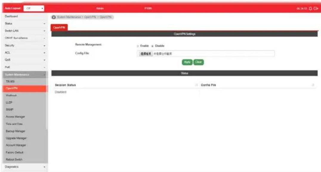
text_image
Auto Input: Off Admin PDR 06.24.13 OpenBoard Status Switch LAN OMF Surveillance Security ACL GoS PoE System Maintenance TR-005 OpenVPN Workload LLDP SNIP Access Manager Time and Date Backup Manager Upgrade Manager Account Manager Factory Default Reboot Switch Diagnostics System Maintenance > OpenVPN > OpenVPN OpenVPN OpenVPN Settings Remote Management: Enable Enable Config File: 组库菜单 未连接访问菜单 Apply Clear Status Session Status Disabled Confio FileAvailable settings are explained as follows:
| Item | Description |
| Remote Management Enable | - Click it to enable OpenVPN tunnel between VigorSwitch with the remote end.Disable - Click it to disable OpenVPN tunnel. |
| Config File As a VPN client | , please import the OpenVPN config file coming from OpenVPN server. |
| Apply Save and apply the settings to the switch. | |
| Status Display current Open | nVPN status (Disabled, Connecting or Success) and configuration file used. |
VIII-3 Webhook
Without getting any request, VigorSwitch will send the data (if available) that a user concerned to the specified URL (provided by remote client) automatically.
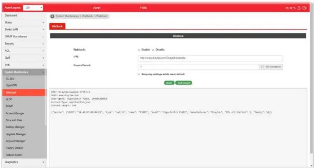
text_image
Auto Logout: Off Agree PMS 05.11.15 Dashboard Status Switch LAN ON/MP Surveillance Security ACL GoS PoE System Maintenance TR/SS Open/VPN Webbook Webbook: URL: Report Period: Enable a Disable http://www.draytek.com.DraytekSample 1 (1 - 32) minute(s) Keep my settings while reset default. Analyze Set Secret POST (Draytek/sample HTTPQL.) Host: www.draytek.com User-Agent: VigarSwitch P485, 1649C0804C9 Contact-Type: application/json Content-Length: less {"device": {"VDD": "14:49:0C:08:B4:C9", "type": "salt10", "name": "F180", "code": "VigarSwitch P485", "manufacture": "Draytek", "CPU utilization": 3, "Henry": 56}.}Available settings are explained as follows:
| Item | Description |
| Webhook | Enable - Click it to enable the webhook service. The data will be transmitted to the specified URL.Disable -Click it to disable the webhook service. |
| URL Specify the destination | to receive the real-time data by entering the URL.Please get the URL from the client who wants to obtain the newest and available data automatically from the switch. |
| Report Period Set the transmission interval (unit is minute).Keep my settings while rest default - Check the box to keep the webhook configuration when resetting VigorSwitch with default settings. | |
| Apply Apply the settings to the switch. | |
| Test Report Vigor system will send a test report to the remote address. | |
VIII-4 LLDP
LLDP is a one-way protocol; there are no request/response sequences. Information is advertised by stations implementing the transmit function, and is received and processed by stations implementing the receive function.
VII-4-1 Properties
This page allows a user to set general settings for LLDP.

text_image
Auto Logout: Off Admin: P1085 05.31.16 Dashboard Status Switch LAN ONVF Surveillance Security ACL QoS PdE System Maintenance TLR-905 Open/PN Workbox LLDP Properties LLDP Port Setting LLDP Local Device LLDP Remote Device LLDP Overloading SNRP Access Manager Time and Date Backup Manager System Maintenance > LLDP > Properties > LLDP Global Setting LLDP Global Setting LLDP State: Enable Disable LLDP PDU/Disable Action: Filtering Bridging Flooding Transmission Interval: 30 (0.32767) Holdtime Multiplex: 4 (0.10) Reclassification Delay: 2 (1.50) Transmit Delay: 2 (1.0151) HelpAvailable settings are explained as follows:
| Item | Description |
| LLDP State Enable - Enable LLDP protocol on this switch.Disable - Disable LLDP protocol on this switch. | |
| LLDP PDU Disable Action | It is available when LLDP State is disabled. Specify the action for VigorSwitch to execute.Filtering - Packets will be dropped.Bridging - Packets will be transmitted to the device within the same VLAN.Flooding - Packets will be transmitted to all ports. |
| Transmission Interval Select the interval at which frames are transmitted. The default is 30 seconds, and the valid range is 5-32768seconds. | |
| Holdtime Multiplier Select the multiplier on the transmit interval to assign to TTL (range 2-10, default = 4). | |
| Reinitialization Delay | Select the delay before a re-initialization (range 1-10 seconds, default = 2). |
| Transmit Delay Select the delay after an LLDP frame is sent (range 1-8192 seconds, default = 3). | |
| Apply Apply the settings to the switch. | |
VIII-4-2 LLDP Port Setting
This page allows a user to select specified port or all ports to configure LLDP state.
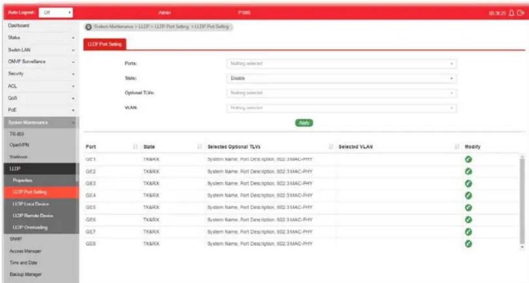
text_image
Auto Logpost Off Admin P005 05.30.25 Dashboard Status Switch LAN ON/VT Surveillance Security ACL QoS PoE System Maintenance TR (00) Open/PN Workbook LLDP Properties LLDP Port Setting LLDP Local Device LLDP Module Device LLDP Overloading Shap1 Access Manager Time and Date Backup Manager System Maintenance > LLDP > LLDP Port Setting > LLDP Port Setting LLDP Port Setting Ports: Nothing selected > State: Disable > Optional TLVs: Nothing selected > VLAN: Nothing selected > Ports Port State Selected Optional TLVs Selected VLAN Modify GE1 TX&RX System Name, Port Description, 802.3 MAC-PHY ✓ GE2 TX&RX System Name, Port Description, 802.3 MAC-PHY ✓ GE3 TX&RX System Name, Port Description, 802.3 MAC-PHY ✓ GE4 TX&RX System Name, Port Description, 802.3 MAC-PHY ✓ GE5 TX&RX System Name, Port Description, 802.3 MAC-PHY ✓ GE6 TX&RX System Name, Port Description, 802.3 MAC-PHY ✓ GE7 TX&RX System Name, Port Description, 802.3 MAC-PHY ✓ GE8 TX&RX System Name, Port Description, 802.3 MAC-PHY ✓Available settings are explained as follows:
| Item | Description |
| Ports Use the drop down list to select the port (GE1 to GE8) or ports for device check. | |
| State | Disable - Disable the transmission of LLDP PDUs.TX&RX - Transmit and receive LLDP PDUs both.TX Only - Transmit LLDP PDUs only.RX Only - Receive LLDP PDUs only. |
| Optional TLVs | Within data communication protocols, optional information may be encoded as a type-length-value or TLV element inside a protocol. TLV is also known as tag-length value.The type and length are fixed in size (typically 1-4 bytes), and the value field is of variable size.Select the LLDP optional TLVs to be carried (multiple selection is allowed).Available items include System Name, Port Description, System Description, System Capability, 802.3 MAC-PHY, 802.3 Link Aggregation, 802.3 Maximum Frame Size, Management Address and 802.1 PVID. |
| VLAN Select the VLAN ID number to be performed (multiple selections are allowed). | |
| Apply Apply the settings to the switch. | |
| Modify | - Click it to modify the settings for the selected port profile. |

text_image
Edit Port GE1 State TX&RX Optional TLVs System Name, Port Description, 802.3 MAC-PHY VLAN Nothing selected OK CancelVIII-4-3 LLDP Local Device
This page displays information for LLDP Local Device.
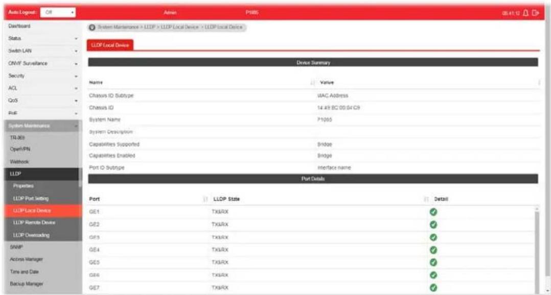
text_image
Auto Logout Dashboard Status Switch LAN ONVF Surveillance Security ACL CoS RUF System Maintenance > LLOP > LLOP Local Device > LLOP Local Device LLOP Local Device Device Summary Name Value Chassis ID Subtype VAC Address Chassis ID 14.49 BC 00 04 C9 System Name 71065 System Description Capabilities Supported Bridge Capabilities Enabled Bridge Port ID Subinge interface name Port Details Port LLOP State Detail GE1 TXLRX ✓ GE2 TXLRX ✓ GE3 TXLRX ✓ GE4 TXLRX ✓ GE5 TXLRX ✓ GE6 TXLRX ✓ GE7 TXLRX ✓Available settings are explained as follows:
| Item | Description |
| Device Summary Display a | summary of the LLDP information for this switch.Chassis ID Subtype - Display the type of chassis ID, such as the MAC address.Chassis ID - Display Identifier of chassis. Where the chassis ID subtype is a MAC address, the MAC address of the switch is displayed.System Name - Display model name of switch.System Description - Display description of switch.Capabilities Supported - Display the primary functions of the device, such as Bridge, WLAN AP, or Router.Capabilities Enabled - Primary enabled functions of the device.Port ID Subtype - Display the type of the port identifier that is shown. |
| Port Details Display detailed | information of the selected GE port.Detail - Click the button under it to review the detailed information contained in TLVs sent out from each interface, containing MAC/ PHY, 802.3, 802.3 Link Aggregation, 802.1 VLAN and Protocol for each LAN port (GE1 to GE8). |
VIII-4-4 LLDP Remote Device
This page allows the network administrator to view the information sent from neighboring devices by LLDP protocol.
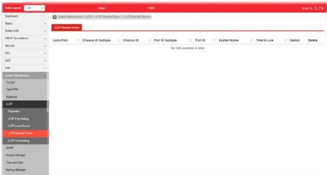
text_image
Auto Logpost Off Admin P085 964673 Dashboard Status Switch LAN ONMF Surveillance Security ACL CoS PeE System Maintenance TR 909 OpenVPN Washock LLDP Properties LLDP Port Setting LLDP Local Device LLDP Remote Device LLDP Overloading SNMP Access Manager Time and Date Backup Manager System Maintenance > LLDP > LLDP Remote Device > LLDP Remote Device LLDP Remote Device Local Port Chassis ID Subtype Chassis ID Port ID Subtype Port ID System Name Time to Live Details Delete No data available in tableAvailable settings are explained as follows:
| Item | Description |
| Local Port | Display the number of the local port to which the neighbor is connected. |
| Chassis ID Subtype | Display the type of chassis ID (for example, MAC address). |
| Chassis ID Display the identifier of the 802 LAN neighboring device's chassis. | |
| Port ID Subtype Display the type of port identifier. | |
| Port ID Display the number of port identifier. | |
| System Name Display the name of the switch. | |
| Time to Live Display the time interval in seconds after which the information for remote device will be deleted. | |
| Details Display detailed information contained in TLVs sent out from neighboring devices. | |
| Delete Click it to remove information of the selected port. | |
VIII-4-7 LLDP Overloading
This page allows user to review current size, overall size of LLDP packet and whether it is to exceed maximum allowed size of single LLDP packet.
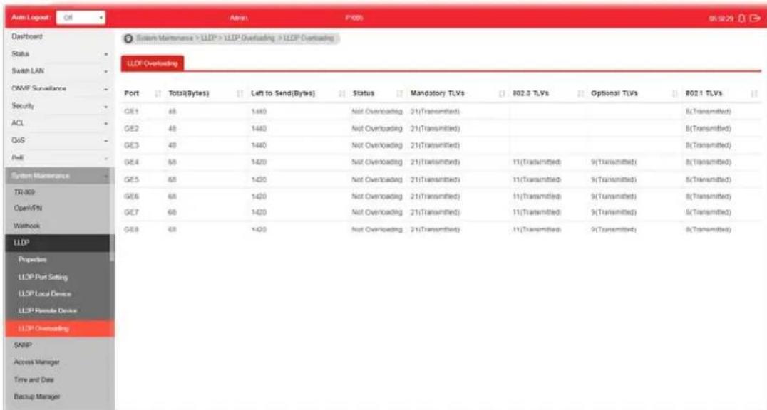
text_image
Auto Logout Dashboard Status Switch LAN ONMF Surveillance Security ACL QoS PHE System Maintenance TR-009 Open/PSN Waltbook LLDP Propulsion LLDP Port Setting LLDP Local Device LLDP Remote Device LLDP Overloading SNMP Access Manager Time and Data Backup Manager System Maintenance > LLDP > LLDP Overloading > LLDP Overloading LLDP Overloading Port Total(Bytes) Left to Send(Bytes) Status Mandatory TLVs 802.3 TLVs Optional TLVs 802.1 TLVs GE1 48 1440 Not Overloading 21(Transmitted) GE2 48 1440 Not Overloading 21(Transmitted) GE3 48 1440 Not Overloading 21(Transmitted) GE4 68 1420 Not Overloading 21(Transmitted) 11(Transmitted) 9(Transmitted) 8(Transmitted) GE5 68 1420 Not Overloading 21(Transmitted) 11(Transmitted) 9(Transmitted) 8(Transmitted) GE6 68 1420 Not Overloading 21(Transmitted) 11(Transmitted) 9(Transmitted) 8(Transmitted) GE7 68 1420 Not Overloading 21(Transmitted) 11(Transmitted) 9(Transmitted) 8(Transmitted) GE8 68 1420 Not Overloading 21(Transmitted) 11(Transmitted) 9(Transmitted) 8(Transmitted)Available settings are explained as follows:
| Item | Description |
| Port Display the name of the port. | |
| Total(Bytes) | Display the total number of bytes of LLDP information in each packet. |
| Left to Send(Bytes) | Display the total number of available bytes left for additional LLDP information in each packet. |
| Status Display if LLDP TLVs has overloaded the PDU maximum size or not. | |
| Mandatory TLVs Display how many bytes used by mandatory TLVs. | |
| 802.3 TLVs Display how many bytes used by 802.3 TLVs. | |
| Optional TLVs Displays how many bytes used by optional TLVs. | |
| 802.1 TLVs Displays how many bytes used by 802.1 TLVs. | |
VIII-5 SNMP
Simple Network Management Protocol (SNMP) is an "Internet-standard protocol for managing devices on IP networks". Devices that typically support SNMP include routers, switches, servers, workstations, printers, modem racks and more.
SNMP is used mostly in network management systems to monitor network-attached devices for conditions that warrant administrative attention.
SNMP is a component of the Internet Protocol Suite as defined by the Internet Engineering Task Force (IETF). It consists of a set of standards for network management, including an application layer protocol, a database schema, and a set of data objects.
An SNMP-managed network consists of three key components:
- Managed device
● Agent - software which runs on managed devices
● Network management station (NMS) - software which runs on the manager
A managed device is a network node that implements an SNMP interface that allows unidirectional (read-only) or bidirectional (read and write) access to node-specific information. Managed devices exchange node-specific information with the NMSs. Sometimes called network elements, the managed devices can be any type of device, including, but not limited to, routers, access servers, switches, bridges, hubs, IP telephones, IP video cameras, computer hosts, and printers.
An agent is a network-management software module that resides on a managed device. An agent has local knowledge of management information and translates that information to or from an SNMP-specific form.
A network management station (NMS) executes applications that monitor and control managed devices. NMSs provide the bulk of the processing and memory resources required for network management. One or more NMSs may exist on any managed network.
VIII-5-1 View
This page allows the network administrator to create MIB views (Management information base) and then include or exclude OID (Object Identifier) in a view.

text_image
Auto Logpost Off Admin P085 J64310K Dashboard Status Switch LAN ONMF Surveillance Security ACL QoS PhE System Maintenance TR (R) Open/PMI Network LLDP SNMP View Group Community User Engine ID Trap Event Notification Access Manager System Maintenance > SNMP > View > View View SNMPView View Name: OID Subtree: Type: Included Excluded Add View IID Subtree Type Delete all 1 IncludedAvailable settings are explained as follows:
| Item | Description |
| View Name Enter a name of the MIB view. | |
| OID Subtree Enter an OID string to be included or excluded from the MIB view. | |
| Type Determine to include or exclude the selected MIBs. | |
| Apply Apply the settings to the switch. | |
VIII-5-2 Group
This page allows the network administrator to group SNMP users and assign different authorization and access privileges.
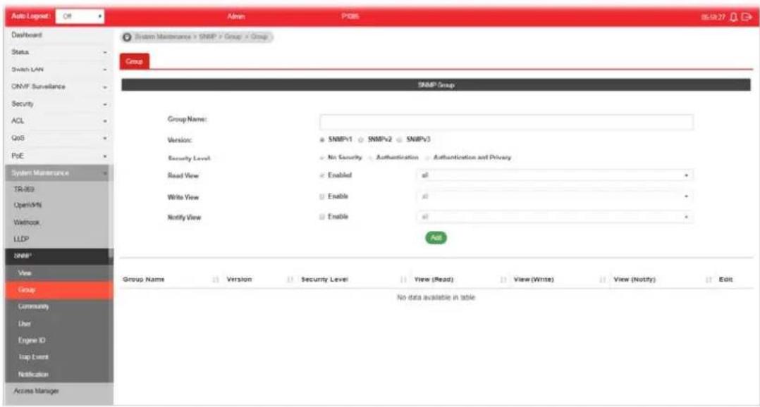
text_image
Auto Logout: Off Admin PDBS 85.59.27 Dashboard Status Switch LAN SNMP Surveillance Security ACL QoS PoE System Maintenance TR-303 Open/4% Wetbook LLDP SNMP* View Group Community User Engine ID Trap Event Notification Access Manager System Maintenance > SNMP > Group > Group Group SNMP Group Group Name: Version: Security Level: Read View: Write View: Notify View: SNMP/1 SNMP/2 SNMP/3 No Security Authentication Authentication and Privacy Enabled Enable Enable Enable Add Group Name Version Security Level View (Read) View (Write) View (Notify) Edit No data available in tableAvailable settings are explained as follows:
| Item | Description |
| Group Name Enter a name | for the group. |
| Version Specify SNMP version. | |
| Security Level Specify SNMP | MP security level for the group. It is available when SNMPv3 is selected.No Security - No authentication and no encryption.Authentication - Requires authentication but no encryption.Authentication and Privacy -Requires authentication and encryption. |
| Read View Enabled - Users | of this group have the right to read the selected MIB view.Use the drop down list to select one of the views. The default is “all”, which means the group user can read all MIB views. |
| Write View Enabled - Users | of this group have the right to write the selected MIB view.Use the drop down list to select one of the views. The default is “all”, which means the group user can write all MIB views. |
| Notify View Enabled - Users | of this group have the right to send notification for the selected MIB view.Use the drop down list to select one of the views. The default is “all”, which means the group user have the right to send notification for all MIB views. |
| Add Click it to create a new group profile. | |
| Edit | Click it to modify the settings for the selected group.click it to remove the selected group. |
VIII-5-3 Community
This page allows a user to add/remove multiple communities of SNMP.
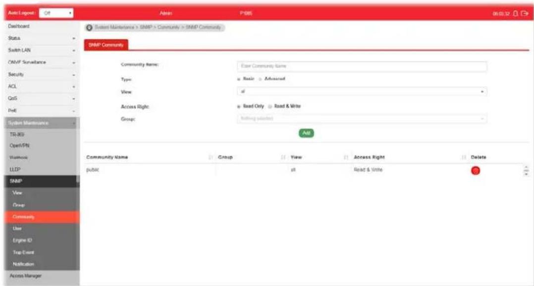
text_image
Auto Layout Dashboard Status Switch LAN ONMF Surveillance Security ACL QoS PdE System Maintenance TR-8G Open/SN Workshop LLFP SNMP View Group Community User Engine ID Trap Event Notification Access Manager Auto P485 06/01/12 Sculent Maintenance > SNMP > Community > SNMP Community SNMP Community Community Name: Enter Community Name Type: Basic Advanced View: of Access Right: Read Only Read & Write Group: Help (start) Add Community Name Group View Access Right Delete public all Read & WriteAvailable settings are explained as follows:
| Item | Description |
| Community Name Enter a | name as community name. The maximum length of the text is limited to 23 characters. |
| Type | Basic - View and access right can be specified for such SNMP community profile.Advanced - Specify one of the SNMP groups for such SNMP community profile. |
| View Simply specify one of | the view profiles (created in SNMP>>View) from the drop down list. |
| Access Right | Read Only - It allows unidirectional access to node-specific information.Read & Write - It allows bidirectional access to node-specific information. |
| Group | Specify the SNMP group configured by user (SNMP>>Group) to define the object available to the community. |
| Add Click it to add a new community. | |
| Delete Click the icon to re | move the selectd community strings. |
VIII-5-4 User
This page allows a user to configure SNMPv3 user profile.
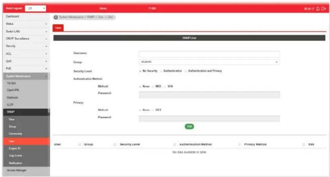
text_image
Auto/Logpost Dashboard Status Switch LAN ON/F Surveillance Security ACL QoS PoE System Maintenance TR/RS Open/PN Watchbox LLDP SNMP View Group Community User Engine ID Trap Event Notification Access Manager Admin PDBS 0619.17 System Maintenance > SNMP > User > User User SNMP User Username: Group: students Security Level: No Security Authentication Authentication and Privacy Authentication Method: Method: None: MOD SHA Password: Privacy: Method: None: OCS Password: All User Group Security Level Authentication Method Privacy Method Edit No data available in table.Available settings are explained as follows:
| Item | Description |
| User Name Enter a name for creating new SNMP user. | |
| Group Choose one of the SNMP group from the drop down list. Then, this user profile will be grouped under the selected SNMP group. | |
| Security Level Display the security level configured for the selected SNMP group. | |
| Authentication Method Method - You can change the methods (None, MD5, SHA) for the selected SNMPv3 group. If no method is available for you to select, that means the selected SNMPv3 group is set with No Security.Password - Enter a string as the password for authentication. | |
| Privacy | Method - You can change the methods (None, DES) for the selected SNMPv3 group. If no method is available for you to select, that means the selected SNMPv3 group is set with No Security.Password - Enter a string as the password for authentication. |
| Add Click it to add a new user profile. | |
| Edit | - click it to modify the settings for the selected profile.- click it to remove the selected entry. |
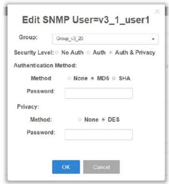
text_image
Edit SNMP User=v3_1_user1 Group: Group_v3_20 Security Level: No Auth Auth Auth & Privacy Authentication Method: Method None MD5 SHA Password: Privacy: Method: None DES Password: OK CancelHowever, if there is no SNMPv3 group ready for use, the following pages will appear instead. Refer to VIII-5-2 Group to create a SNMPv3 group first.

text_image
No SNMP V3 group available. Go to Group function to configure. OK
text_image
Dashboard Status Switch LAN ONVF Surveillance Security ACL QoS System Maintenance TR-059 OpenPH Weblock LLDP SNMP View Group Community Line Engine ID Test Event Notification Access Manager Time and Date System Maintenance + SNMP - User + Group Group SNMP Group Group Name: Version: SNMPv1 SNMPv2 SNMPv3 Security Level: No Security Authentication Authentication and Privacy Read View: Enabled a! Write View: Enable a! Notify View: Enape a! Add Group Name Version Security Level View (Read) View (Write) View (Notify) Edit No data available in tableVIII-5-5 Engine ID
VIII-5-5-1 Local Engine ID
This page allows a user to configure and display SNMP local engine ID.
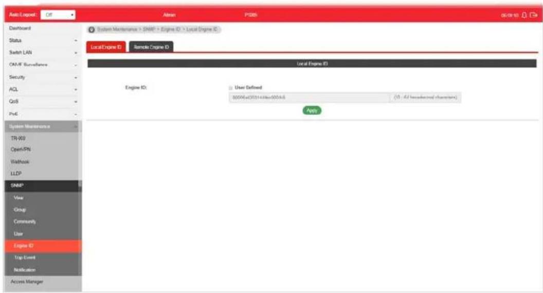
text_image
Auto/Logpost: Off Admin P385 system maintenance > SNMP > Engine ID > Local Engine ID Local Engine ID Remote Engine ID Local Engine ID Engine ID: User Defined 90046eC011438e60046 (1) - All headwind chantain App System Maintenance TR-959 Open/PN Waltbox LLDP SNBP* View Group Commenty User Engine ID Trip Event Notification Access ManagerAvailable settings are explained as follows:
| Item | Description |
| Engine ID | The user defined engine ID is range 10 to 64 hexadecimal characters, and the hexadecimal number must be divided by “2”.User Defined - If it is checked, the local engine ID will be configured manually. If not, the default Engine ID which is made up of MAC and Enterprise ID will be used instead. |
| Apply Apply the settings to the switch. | |
VIII-5-5-2 Remote Engine ID
This page allows a user to configure and display SNMP remote engine ID.
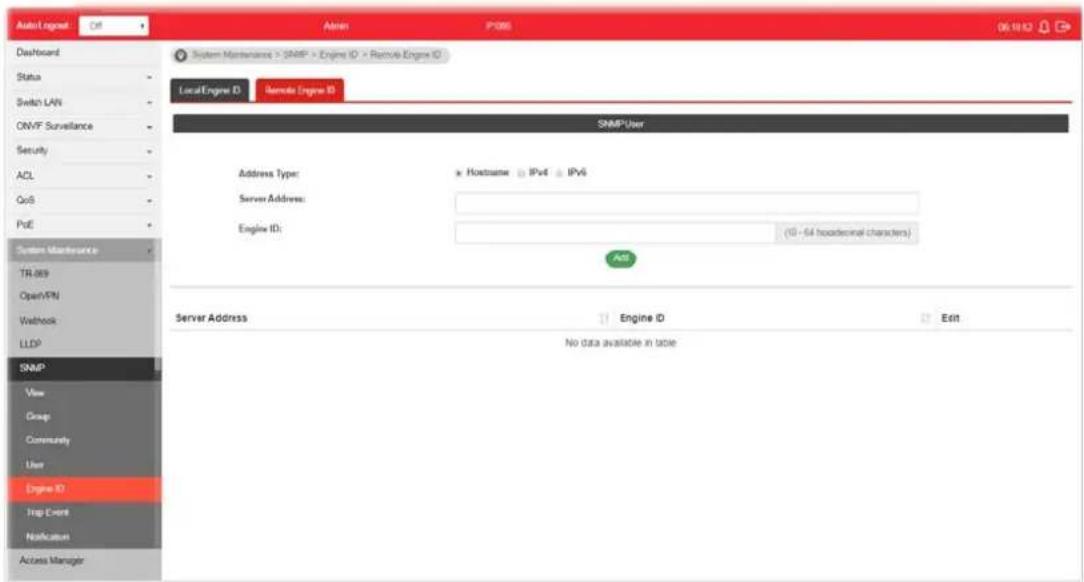
text_image
AutoLogout C#: Admin P385 06.10.12 Dashboard Status Switch LAN ONVF Surveillance Security ACL QoS PoE System Maintenance TR 869 OpenVPN Webbook LLDP SNMP View Group Community User Engine ID Trip Event Notification Access Manager System Maintenance > SNMP > Engine ID > Remote Engine ID LocalEngine ID Remote Engine ID SNMP User Address Type: x Hostname IPv4 IPv6 Server Address: Engine ID: (10 - 54 headcount characters) Add Server Address: Engine ID Edit No data available in tableAvailable settings are explained as follows:
| Item | Description |
| Address Type | Specify the address type for entering hostname or IPv4/IPv6 address. |
| Server Address Enter the | IP address or the host name of the SNMP server. |
| Engine ID Specify the engine ID for remote SNMP server.The engine ID is range10 to 64 hexadecimal characters, and the hexadecimal number must be divided by 2. | |
| Add Click it to create a new profile. | |
| Edit |  |
VIII-5-6 Trap Event
This page allows a user to add or delete SNMP trap receiver IP address and community name.
text_image
Auto Logus: Of Admin P1985 06.12.41 Dashboard Status Switch LAN ONVF Surveillance Security ACL QoS PdE System Maintenance TR-003 Open/PN Waltrock LLDP SNMP View Group Community User Engine ID Top Event Notification Access Manager System Maintenance > SNMP > Top Event > Top Event Top Event Authentication Failure: Link Up / Down: Cold Start: Warm Start: Enable Enable Enable ApplyAvailable settings are explained as follows:
| Item | Description |
| Authentication Failure Enable | - VigorSwtich will reboot when encountering authentication failure (including community not match or user password not match). |
| Link Up / Down Enable - VigorSwtich will reboot while encountering port link up or down trap. | |
| Cold Start Enable - VigorSwtich will reboot while encountering user trap. | |
| Warm Start Enable - VigorSwtich will reboot while encountering power down trap. | |
| Apply Apply the settings to the switch. | |
VIII-5-7 Notification
This page allows a user to configure a host to receive SNMPv1/ v2/ v3 notification.

text_image
Auto/Logout Off Admin PH66 OK 121 Dashboard Status Switch LAN OMVF Subscales Security ACL QoS Pvt System Maintenance TR-DB Open/VPN Networks LLDP SNMP View Group Community User Engine ID Trap Event Notification Access Manager System Maintenance > SNMP > Notification > Notification Notification Notification Address Type: Hostname IPv4 IPv6 Server Address: Version: SNMP=1 SNMP=2 SNMP=1 Type: Trap Inform Community/user public Security Level: No Security Authentication Authentication and Privacy Server Port: Use Default MS (1 - 80120, default 102) Timeout: Use Default sE sec (1 - 300, default 15) Retry: Use Default 3 (1 - 25E, default 3) Add Index Server Address Server Port Timeout Retry Version Type Communication/User security Level Edit No data available in tableAvailable settings are explained as follows:
| Item | Description |
| Address Type Choose IPv4 | IPv6/ Hostname to specify IP address or the hostname of the SNMP trap recipients. |
| Server Address Enter the | IP address of SNMP server based on the address type selected above. |
| Version Specify SNMP notification version (SNMPv1/ v2/ v3). | |
| Type Specify Notification | TypeTrap -Send SNMP traps to the host.Inform - Send SNMP informs to the host. If it is used, Timeout and Retry also shall be defined. |
| Community/user Use the drop down list to choose one of the community profiles. | |
| Security Level | Specify SNMP security level for SNMP notification packet. It is available when SNMPv3 is selected.No Security - No authentication.Authentication - Authentication without encryption will be performed for packets.Authentication and Privacy - Authentication with encryption will be performed for packets. |
| Server Port Specify the UDP port number for the recipient's server.Use Default - If it is checked, the default number (162) will be used automatically. | |
| Timeout | Specify the SNMP informs timeout. It is available whenInformis selected as Type.Use Default - If it is checked, the default number (15) will be used automatically. |
| Retry Specify the SNMP informs retry count. It is available whenInformis selected as Type.Use Default- If it is checked, the default number (3) will be used automatically. | |
| Add Click it to create a new notification profile. | |
| Edit |  |
VIII-6 Access Manager
This page allows the network administrator to control availability of management services such as HTTP, HTTPS, Telent and SSH.
text_image
Auto Logout OS Admin P3885 06:15:36 Dashboard Status Switch LAN ON/IF Surveillance Security ACL QoS PoE System Maintenance TR-909 Open/PN Workforce LLDP SNAP Access Manager Time and Date Bataup Manager Upgrade Manager Account Manager Factory Default Robotic Switch Diagnostics System Maintenance > Access Manager > Access > Access Access Settings HTTP Service: Enable Disable HTTP3 Service: Enable Disable Enforce HTTPS Management: Enable Disable TLS Minimum Protocol Version: TL 51.2 TL 51.3 Telnet Service: Enable Disable JNJ Services: Enable Disable ApplyAvailable settings are explained as follows:
| Item | Description |
| HTTP Service HTTP is the | acronym of HyperText Transfer Protocol. Enabled -Click it to enable HTTP service. |
| HTTPS Service HTTPS is the | the acronym of Hypertext Transfer Protocol over Secure Socket Layer. Enabled - Click it to enable HTTPS service. |
| Enforce HTTPS Management | Enabled - Users will be forced to access into the web user interface of VigorSwitch by HTTPS protocol. |
| TLS Minimum Protocol Version | TLS1.2 / TLS 1.3 - VigorSwitch supports TLS1.2 and TLS 1.3 protocols for web browsing. Select one of the versions as a protocol for having higher connection security. |
| Telnet Service Telnet is the | TCP/IP standard protocol for remote terminal service. TELNET allows a user at one site to interact with a remote timesharing system at another site as if the user's keyboard and display connected directly to the remote machine. Disabled - Click it for not accessing telnet service. Enabled - Click it to access telnet service. |
| SSH Service Enabled - Enable SSH service. | |
| Apply Apply the settings to the switch. | |
VIII-7 Time and Date
VIII-7-1 System Time Zone
This page allows a user to specify where the time of VigorSwitch should be inquired from.

text_image
Auto Logover: Off Admin: P1005 06/17/32 Dashboard Status Switch LAN ONVF Surveillance Security ACL QoS PoE System Maintenance TR-93 OpenAPIs Washock LLDP SNAP Access Manager Time and Odb Backup Manager Upgrade Manager Account Manager Factory Default Robot Switch Diagnostics System Maintenance > Time and Date > System Time Zone System Time Zone: Time System Time Zone Setting Auto Detect Time Zone: Enable Daylight Saving Time: Disable System Time Zone Information Current Data/Time 06/17/24 (07:48) Jan 2005 Time zone UTC+8 Auto Time Zone Status Detecting Daylight Saving Time DisabledAvailable settings are explained as follows:
| Item | Description |
| System Time Zone Setting | |
| Auto Detect Time Zone | Select Enable to make Vigor router detect the time zone that VigorSwitch is located automatically. |
| Daylight Saving Time Select | the mode of daylight saving time.Disable -Disable daylight saving time.Recurring - Using recurring mode of daylight saving time.Non-Recurring - Using non-recurring mode of daylight saving time.USA -Using daylight saving time in the United States that starts on the second Sunday of March and ends on the first Sunday of November.European - Using daylight saving time in the Europe that starts on the last Sunday. |
| Daylight Saving Time Offset | It is available when Recurring is selected as Daylight Saving Time.Specify the adjust offset of daylight saving time. |
| Recurring From / To | It is available when Recurring is selected as Daylight Saving Time.From - Specify the starting time of recurring daylight saving time.To - Specify the ending time of recurring daylight saving time. |
| Non-recurring From / To | It is available when Non-Recurring is selected as DaylightSaving Time.From - Specify the starting time of non-recurring daylight saving time.To - Specify the ending time of recurring daylight saving time. |
| Apply Apply the settings to the switch. | |
| System Time Zone Informations | Display the status of system time zone. |
VIII-7-2 Time
This page allows a user to specify time and activate SNTP server manually.

text_image
Auto/Lognet Off Admin F1005 07:30:36 Dashboard Status Switch LAN ON/F Surveillance Security ACL QoS PoE System Maintenance TR-SS Open/PN Wetbrook LLDP SNMP Access Manager Time and Date Backup Manager Upgrade Manager Account Manager Factory Default Reboot Switch Diagnostics System Maintenance > Time and Date > Time System Time Zone Time Manual Time: Year 2008 Month Jan Day 2 Hours 7 Minutes 25 Seconds Enable SNTP: SNTP/NTP Server Address: Server Port: Enable Disable poolmpgang [XXXX] or Hostname] 123 [1 - 63325 (Default : 123)] Apply OKAvailable settings are explained as follows:
| Item | Description |
| Manual Time | Specify static time (year, month, day, hours, minutes and seconds) manually. |
| Enable SNTP Enable - Click it to enable SNTP time server.Disable - Click to disable the time server. | |
| SNTP/NTP Server Address | Enter the web site of the time server or the IP address of the server. |
| Server Port Enter the port | number use by the time server. |
| Apply Apply the settings to the switch. | |
VIII-8 Backup Manager
Backup Manager allows a user to backup the firmware image or configuration file on the switch to remote TFTP server or host file system through HTTP protocol.

text_image
Auto Lognet Ctrl Admin P1005 87.27.49 Dashboard Status Switch LAN ON-N^ Sur-reference Security ACL QoS PvE System Maintenance TR-SEI Open/PN Vietbrook LLDP SNAP Access Manager Time and Date Backup Manager Upgrade Manager Account Manager Factory Default Reboot Setan Diagnostics System Maintenance > Backup Manager > Backup Manager Backup Manager Backup Method: TFTP Server IP: Enter Server IP Backup Type: e- Configuration Apply (IPv4 or IPv6 Address)Available settings are explained as follows:
| Item | Description |
| Backup Method Select Backup method. | TFTP - Using TFTP to backup firmware. |
| HTTP - Using WEB browser to ubackup firmware. | |
| Server IP It is available when TFTP is selected as Backup Method.Enter the IPv4/ IPv6 address for the TFTP server. | |
| Backup Type Configuration - Make a backup copy for the configurations for VigorSwitch. | |
| Apply Apply the settings to the switch. | |
VIII-9 Upgrade Manager
Backup Manager allows a user to upgrade the firmware image or configuration file on the switch to remote TFTP server or host file system through HTTP protocol.

text_image
Auto Logpost Off Admin P1986 07/2027 Dashboard Status Switch LAN OM/F Surveillance Security ACL CoS PoE System Maintenance TR-CEB OpenVPN Vnothing LLDP SNMP Access Manager Time and Date Backup Manager Upgrade Manager Account Manager Factory Default Reboot Switch Diagnostics System Maintenance > Upgrade Manager > Upgrade Manager Upgrade Manager Upgrade Method: HTTP FilePaths: 模型框架 - 未提供结构框架 Upgrade Type: Image Configuration ApplyAvailable settings are explained as follows:
| Item | Description |
| Upgrade Method Select Upgrade method:TFTP - Using TFTP to upgrade firmware.HTTP - Using WEB browser to upgrade firmware. | |
| Server IP | It is available when TFTP is selected as Upgrade Method.Enter the IPv4/ IPv6 address for the TFTP server. |
| File Name | It is available when TFTP is selected as Upgrade Method.Enter the firmware image or configuration file name on the TFTP server. |
| File/Path | It is available when HTTP is selected as Upgrade Method.Choose the firmware file located in your computer. |
| Upgrade Type Image - Click it to upgrade the firmware image.Configuration - Click ito to upgrade the configurations for VigorSwitch. | |
| Apply Apply the settings to the switch. | |
VIII-10 Account Manager
This page allows a user to add or delete local user on switch database for authentication. The configuration result for each port will be displayed on the table listed on the lower side of this web page.

text_image
Auto Logpost OS Admin P1000L 22:36:42 Dashboard Status Switch LAN ONAP Surveillance Security ACL QoS PyE System Maintenance TR 603 Open/PN Wetrock LLDP SNAP Access Manager Time and Date Backup Manager Upgrade Manager Account Manager Factory Default Reload Switch Diagnostics System Maintenance > Account Manager > Local User Information Local User Information Account Username: Enter Usname Password: Enter Password Password Strength: Block Medium Minimum Btype Password: Enter Password Privilege Level: Admin Apply Local Users Username Password Type Privilege Type Modify admin Enrypted AdminAvailable settings are explained as follows:
| Item | Description |
| User Name Enter a username | If you want to modify an existed user account, simply enter the same string in this field. Then, modify the password and choose privilege level. After clickingApply, the existed user name will be modified with different values. |
| Password Enter a password | for new account. |
| Password Strength Display | the strength (weak, medium, or strong) of the password entered above. |
| Retype Password | Retype password to make sure the password is exactly you typed before in “Password” field. |
| Privilege Level Use the drop down list to select privilege level (Admin/ User) for new account.Admin - Allow to change switch settings.User - See switch settings only. Not allow to change it. | |
| Apply Apply the settings to the switch. | |
| Delete Remove the selected account. | |
| Edit | Click it to modify the settings for the selected user profile.Click it to remove the selected entry. |
text_image
Edit User: admin Edit Password: Disabled Privilege Type: Admin OK CancelVIII-11 Factory Default
Click Apply to return to factory default settings for VigorSwitch.
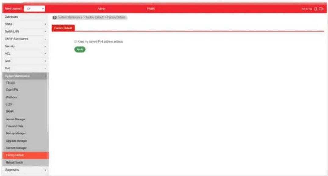
text_image
Auto Lognet Off Admin P1085 S2 2019 Dashboard Status Switch LAN ONVP Surveillance Security ACL QoS PvE System Maintenance TR 969 Open/PN Wethrock LLDP SNIP Access Manager Time and Date Bancup Manager Upgrade Manager Account Manager Factory Default Robust Switch Diagnostics System Maintenance > Factory Default > Factory Default Factory Default Keep my current IPv4 address settings. PvEIf Keep my current IPv4 address settings is checked, after clicking Apply, the original configuration for IP address will be kept.
VIII-12 Reboot Switch
Click Apply to reboot VigorSwitch with current settings.
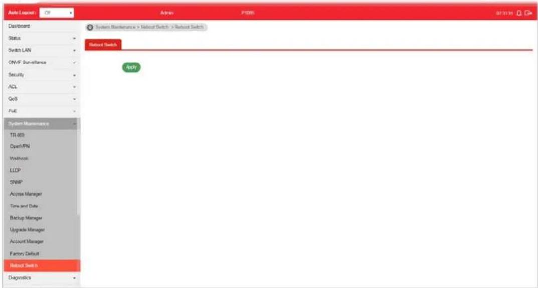
text_image
Auto Server OP Admin P1005 07/31/31 Dashboard Status Switch LAN ONVF Surveillance Security ACL QoS PUE System Maintenance TR 803 Open/PIN Workshop LLDP SNIP Access Manager Time and Data Backup Manager Upgrade Manager Account Manager Factory Default Reset Switch Diagnostics System Maintenance > Reset Switch > Reset Switch Reset Switch ApplyThis page is left blank.
Part IX Diagnostics
IX-1 Device Check
After finished copper test, the results will be shown on the lower side of this web page.
This page is used to configure device check of PoE PD devices. It can be applied to PoE PD devices connected directly, check ping echo status, and forcibly reboot the device when meeting the preset health condition.
The configuration result for each port will be displayed on the table listed on the lower side of this web page.

text_image
Auto Logpost Off Admin P085 API Server Dashboard Status Switch LAN CM/F Surveillance Security ACL QoS PvE System Maintenance Diagnostics Device Check Cable Diagnostics PingTest SysLag Mail Alert Product Registration Diagnostics > Device Check > Device Check Device Check Port: GE1 Enable: Enable * Disable Ping IP Address: 0.000 (PvE, up to 10IP addresses) Interval Time (sec): 15 Retry Time: 1 Failure Action: Nothing Note: PvE unsupported port will be set to "Nothing". Mail Alert: Enable * Disable Apply Port Enable Ping IP Addr Interval Times (s) Retry Time Failure Action Mail Alert GE1 Disabled 0.0.00 15 1 Nothing Disabled GE2 Disabled 0.0.00 15 1 Nothing Disabled GE3 Disabled 0.0.00 15 1 Nothing Disabled GE4 Disabled 0.0.00 15 1 Nothing DisabledAvailable settings are explained as follows:
| Item | Description |
| Port Use the drop down list | to select the port (GE1 to GE8) or ports for device check. |
| Enable Disable - No PoE | function for the selected GE port.Enable - PoE function will be enabled for the selected GE port. |
| Ping IP Address Enter the | IP address of the PoE device for check. |
| Interval Time (sec.) The ping | ing check will be performed every 10, 30, 60 or 120 seconds for the selected port (PoE device). |
| Retry Time | The system will perform the ping check the selected port (PoE device) for 1, 3 or 5 times. |
| Failure Action Specify the | action performed for PoE device when there is no number of retry time of echo from given IP address.Power Cycle - Forcely reboot the device by cycling the power given to PoE device.Power Off - The PoE divice will be powered off.Nothing - Log this event only, no action is taken on PoE device. |
| Mail Alert Enable - Click it | to enable the mail alert function.Disable - Click it to disable the mail alert funciton. |
| Apply Save the settings or | changes to the switch. |
IX-2 Cable Diagnostics
After finished copper test, the results will be shown on the lower side of this web page.
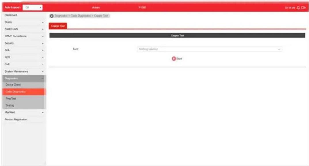
text_image
Auto Logset Off Admin P1005 07 March 2019 Dashboard Status Switch LAN ONVF Surveillance Security ACL QoS PUE System Maintenance Diagnoses Device Check Cable Diagnostics Ping Test Syslog Mail Alert Product Registration Diagnosis > Cable Diagnostics > Copper Test Copper Test Copper Test Port: Nothing selected StartAvailable settings are explained as follows:
| Item | Description |
| Port Use the drop down list | to select the port (GE1 to GE8) or ports for performing cable diagnostics. |
| Start Perform the copper test action. | |
IX-3 Ping Test
After finished the ping test, the results will be shown on the lower side of this web page.

text_image
Auto Logout: Of Admin P105 BY 3654 Davonard Status Switch LAN ONVF Surveillance Security ACL QoS Poly System Maintenance Diagnosis Device Check Cable Diagnostics Png Test Systag Mail Alert Product Registration Diagnostics > Ping Test > Ping Test Ping Test Protocol: IP-4 Host: (IP-4 address or hostframe) Count: 4 (1 - 5) Internal (sec): 1 (1 - 3) Start StopAvailable settings are explained as follows:
| Item | Description |
| Protocol Choose IPv4/ IPv6 | to specify IP address for sending ping to check if network path is ok. |
| Host Enter the IP address of SNMP server based on the protocol selected above. | |
| Count | It means how many times to send ping request packet.Enter a number between 1 and 5 as the count and the default configuration is 4. |
| Interval(sec) Define the interval to perform ping action. For example, “1” means the ping action will be performed per second. | |
| Start Perform ping action. | |
| Stop Terminate ping action. | |
IX-4-1 SysLog Explorer
After clicking View, the results will be shown on the lower side of this web page.
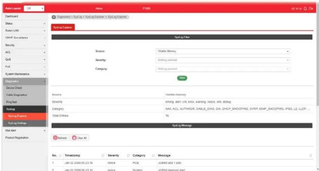
text_image
AutoLog Post Off Admin P1005 or 37.41 Dashboard Status Switch LAN OMF Sum-Insurance Security ACL QoS PUE System Maintenance Diagnodes Device Check Cable Diagnostics Ping Test SysLog SysLog Explorer SysLog Ratings Mail Alert Product Registration Diagnostic > SysLog > SysLog Explorer > SysLog Explorer Syst.org Provider Syst.org Filter Source: Volatile Memory Severity: Nothing selected Category: Nothing selected Value Source Variable Memory Severity enterg, alert, crit, error, warning, notice, info, debug Category: AAA, ACL, AUTHMGR, CABLE_DIAG, DIAL, DHCP_SNOOPING, SVRP, SNMP_SNOOPING, IPSS, L2, LLDP, ... Total Entries: 16 SysLog Message Refresh Clear All No. Timestamp Severity Category Message 1 Jan 02 2000 05:23:15 notice PCE JOBSD add 1 jobt 2 Jan 02 2000 05:23:15 notice System JOBSD daemon startAvailable settings are explained as follows:
| Item | Description |
| Source | ● Volatile Memory - Explore the logs contained in volatile memory (also known as RAM).● Non-Volatile Memory - Explore the logs contained in non-volatile memory (also known as Flash). |
| Severity Select severity (emerg, alert, crit, error, warning, notice, info and debug) of log messages which you wish to filter out for review. | |
| Category | Select the categories (related features) of logs you wish to review.Category contains AAA, ACL, AUTHMGR, CABLE_DIAG, DAI, DHCP_SNOOPING, GVRP, IGMP_SNOOPING, IPSG, L2, LLDP, Mac-based VLAN, Mirror, MLD_SNOOPING, Platform, PM, Port, PORT_SECURITY, QoS, Rate, SNMP, STP, Security suite, System, Surveillance VLAN, Trunk, UDLD and VLAN. |
| View Click it to display logs based on the settings configured above. | |
| Refresh Click it to refresh the log. | |
| Clear All Clear it to remove all logs displayed in this page. | |
IX-4-2 SysLog Settings
IX-4-2-1 SysLog Service
This page allows user to enable system logging into local syslog and specific remote syslog server for storage.
text_image
Audio Logset Oil Dashboard Status Switch LAN ON-MT Surveillance Security ACL QoB PcE System Maintenance Diagnostics Device Check Calls Diagnostics Ping Test Syslog SysLog Explorer SysLog Settings Mail Alert Product Registration Adams IP308 07.16.14 Diagnostics > SysLog > SysLog Settings > SysLog Service SysLog Service Local SysLog Hammers SysLog SysLog Mail SysLog Service: Enable Disable ApplyAvailable settings are explained as follows:
| Item | Description |
| SysLog Service | ● Enable - Click it to activate function of syslog. ● Disable - Click it to inactivate the function. |
| Apply Apply the settings to the switch. | |
IX-4-2-2 Local SysLog
This page allows user to enable logging into volatile memory or non-volatile memory.
text_image
Admin1_Output CIR Admin P-1005 07:30:02 Dashboard Status Switch LAN ONMT Surveillance Security ACL CoS Push System Maintenance Diagnosis Device Check Data Diagnosis Ping Test SYSLag SYSLag Explorer SYSLag Settings Mail Alert Product Registration Diagnosis > SySLag > SySLag Settings > Local SySLag SySLag Summary Local SySLag Demethyl SySLag SySLag Mail Local SySLag Settings Source: Nothing selected Severity: emerg Apply Source Status Severity Delete Volatile Memory enapped(emrg, alert, crit, error, warning, notice)Available settings are explained as follows:
| Item | Description |
| Source | ● Volatile Memory - Select the volatile memory for saving local log. Volatile memory does not hold the log after reboot or power off. ● Non-Volatile Memory - Select the non-volatile memory for saving.If you want to modify Volatile Memory / Non-Volatile Memory, select Volatile Memory / Non-Volatile Memory in this field. Then, use the drop down list of severity to specify type of log message. After clicking Apply, the Volatile Memory / Non-Volatile Memory will be modified with new configured severity level. |
| Severity Select severity (emerg, alert, crit, error, warning, notice, info and debug) of log messages which will be stored. | |
| Apply Apply the settings to the switch. | |
| Delete Remove all logs displayed in this page. | |
IX-4-2-3 Remote SysLog
This page allows user to enable system logging into specific remote syslog server for storage.
After clicking Apply, the results will be shown on the lower side of this web page.
text_image
Auto Logout: Off Admin: IP306 874142 Dashboard Status Switch LAN ON/IF Surveillance Security ACL QoS PUE System Maintenance Diagneters Device Check Cellu Diagneters Prog Test Syslog SysLog Explorer SysLog Settings Mail Next Product Registration Diagnosis = SysLog = SysLog Settings = Remote SysLog SysLog Service Local SysLog Remote SysLog SysLog Mail Remote SysLog Settings Server Address: Enter Server Address Server Port: £14 (1 - 65535) Severity: emerg Facility: local No Data Available in Table Server IP(Port) Status Severity Facility Delete No data available in tableAvailable settings are explained as follows:
| Item | Description |
| Server Address Enter the | IP address of Syslog server. |
| Server Port | Specify the port that syslog should be sent to. |
| Severity Select severity (emerg, alert, crit, error, warning, notice, info and debug) of log messages which will be stored. | |
| Facility One device supports multiple facilities (represented with facility ID, local0 to local7) of remote Syslog server. For each facility ID contains different syslog server configuration, please choose a facility ID for such Syslog server. | |
| Apply Apply the settings to the switch. | |
| Delete Remove specific remote syslog entry. | |
IX-4-2-4 SysLog Mail
This page allows user to enable system logging into specific remote syslog server for storage.
After clicking Apply, the results will be shown on the lower side of this web page.

text_image
Aloq Logout Ctrl Admin PRTS 07:42:25 Dashboard Status Switch LAN OMNT Surveillance Security ACL QoS PWM System Maintenance Diagnostics Device Check Cable Diagnostics Ping Test SysLog SysLog Explorer SysLog Settings Mail Alert Product Registration Diagnosis > SysLog > SysLog Settings > SysLog Mail SysLog Service Local SysLog Remote SysLog SysLog Mail Status: Category: SMTP Server: SMTP Port: Authentication: Encryption: Sender: Email Address: Enable * Disable Nothing selected 1.2.3 file anti-example.com 2% Enable * Disable Disable sender: receiver@example.com (Setting may not be applied or some sensors.) receiver@example.com receiver2@example.com... Apply Send text mailAvailable settings are explained as follows:
| Item | Description |
| State | Enable - Enable the function of Syslog Mail.Disable - Disable the function of Syslog Mail. |
| Category Vigor sytem will | send the e-mail related to the selected feature(s) to the recipient. |
| SMTP Server Enter IP address or URL of the SMTP server. | |
| SMTP Port Enter the port number for the SMTP server. | |
| Authentication | Enable - Click it to enable authentication mechanism.●Username - Enter a user name for authentication.●Password - Enter a password for authentication. |
| Encryption After enabling | Authentication, choose one of the encryption servers for data encryption.●StartTLS - The mail will be encrypted with StartTLS.SSL/TLS - The mail will be encrypted with SSL/ TLS.Disable - The mail sent out will not be encrypted. |
| Sender Enter the email address which will send the syslog mail out. | |
| Email Address Enter the email address which will receive the syslog mail. | |
| Apply Apply the settings to the switch. | |
| Send test mail | After clicking this button, VigorSwitch system will send a test mail to the recipient. |
Part X Mail Alert
X-1 Alert Setting
This page allows a user to configure settings for VigorSwitch to send alert mail when encountering certain situation.
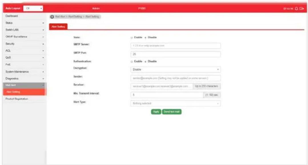
text_image
Auto Layout Off Admin P488 Database Dashboard Status Switch LAN ONVP Surveillance Security ACL QoS PuC System Maintenance Diagnostics Mail Alert Alert Setting Product Registration Mail Alert > Alert Setting > Alert Setting Alert Setting State: SMTP Server: SMTP Port: Authentication: Encryption: Sender: Receiver: Min. Transmit Interval: Alert Type: Enable < Disable 1.23.6 or config.example.com 2% Enable < Disable Disable sender@example.com (Setting may not be applied on some server) receiver=request@example.com/receiver2@example.com... Up to 255 characters 5 (1 - 60) sec. Nothing selected Apply Send test mailAvailable settings are explained as follows:
| Item | Description |
| State | Enable - Click it to enable the mail alert function.Disable - Click it to disable the mail alert funciton. |
| SMTP Server Enter IP address or URL of the SMTP server. | |
| SMTP Port Enter the port number for the SMTP server. | |
| Authentication | Enable - Click it to enable authentication mechanism.User Name - Enter a user name for authentication.Password - Enter a password for authentication. |
| Encryption After enabling | Authentication, choose one of the encryption servers for data encryption.StartTLS - The mail will be encrypted with StartTLS.SSL/TLS - The mail will be encrypted with SSL/ TLS.Disable - The mail sent out will not be encrypted. |
| Sender Enter the email address which will send the alert mail out. | |
| Receiver Enter the email address which will receive the alert mail. | |
| Min. Transmit Interval | Set a time interval for VigorSwitch system to send an alert out from the specified sender. |
| Alert Type Specify the condition(s) for VigorSwitch system to send an alert out.Port Link StatusPort Link SpeedSystem RestartedPoE Warning Status | |
| ● IP Conflict● Device Check● ONVIF Throughput Threshold | |
| Apply Apply the settings to the switch. | |
| Send test mail | After clicking this button, VigorSwitch system will send a test mail to the recipient. |
This page is left blank.
Part XI Telnet Commands
XI-1 Accessing Telnet of VigorSwitch
This chapter also gives you a general description for accessing telnet and describes the firmware versions for the routers explained in this manual.

Info
For Windows 7 user, please make sure the Windows Features of Telnet Client has been turned on under Control Panel>>Programs.
Type cmd and press Enter. The Telnet terminal will be open later.
text_image
Programs (1) cmd See more results cmdIn the following window, type Telnet 192.168.1.224 as below and press Enter. Note that the IP address in the example is the default address of the router. If you have changed the default, enter the current IP address of the router.
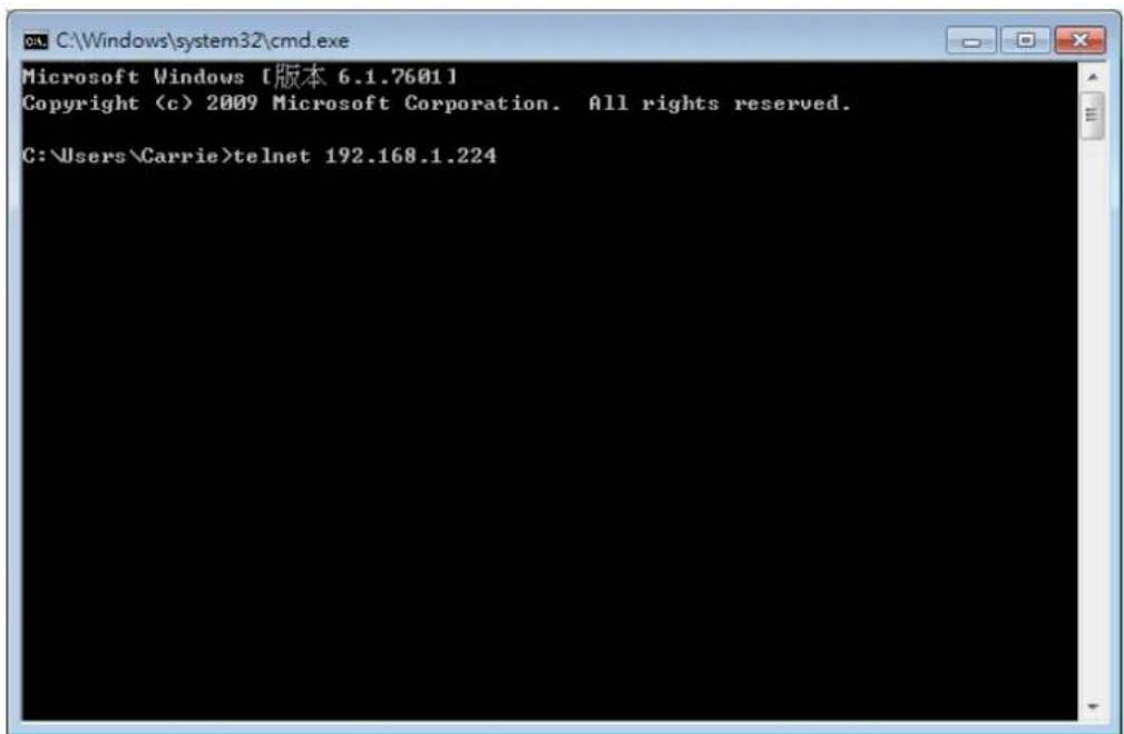
text_image
Microsoft Windows [版本 6.1.7601] Copyright (c) 2009 Microsoft Corporation. All rights reserved. C:\Users\Carrie>telnet 192.168.1.224Next, enter admin/ admin for Account/ Password.
For users using previous Windows system (e.g., XP), simply click Start >> Run and type Telnet 192.168.1.224 in the Open box.
Next, enter admin/admin for Account/Password.
XI-2 Available Commands
Enter ? to get a list of available commands.

text_image
Username: admin Password: ***** P1085# clear Reset functions clock Manage the system clock configure Configuration Mode copy Copy from one file to another delete Delete a file from the flash file system disable Turn off privileged mode command end End current mode and change to enable mode exit Exit current mode and down to previous mode hardware-monitor Hardwarefan test ping Send ICMP ECHO_REQUEST to network hosts reboot Halt and perform a cold restart restore-defaults Restore to default save Save running configuration to flash show Show running system information ssl Setup SSL host keys terminal Terminal configuration traceroute Trace route to network hosts P1085# _The available commands contain - clear, clock, configure, copy, delete, disable, end, exit, hardware-monitor, ping, reboot, restore-defaults, save, show, ssl, terminal, and traceroute. Each command will be explained as follows.
Note: You can also enter ? to check if there are subcommands under current command.
XI-2-1 Clear Configuration
This command allows resetting the functions of ARP, interface, IP, IPv6, LACP, Line, LLDP, Logging, MAC, and Spanning Tree.
Te Inet Command: clear arp
Use this command to clear entries in the ARP cache.
Syntax Items
clear arp
Description
| Syntax Items Description | |
| clear arp- Enter the IP address of the device (e.g., 192.168.1.224).Related Syntax:# clear arp# clear arp | |
Example
P1085# clear arp 192.168.1.224
P1085#
Telnet Command: clear interfaces
Use this command to clear statistics counters for all interfaces or a specific interface (LAN or LAG).
Syntax Items
clear interfaces GigabitEthernet
clear interfaces LAG
Description
| Syntax Items Description | |
| clear interfacesGigabitEthernet | Specify a LAN interface for clearing statistics counters on that port.<1-8> - Enter the number (1 to 8) of LAN port.Related Syntax:□ # clear interfaces gigabitEthernet <1-8> counters |
| clear interfaces LAG | Specify a LAG interface for clearing statistics counters on that port.<1-8> - Enter the number (1 to 8) of LAG interface (IEEE 802.3 Link Aggregation Interface).Related Syntax:□ # clear interfaces LAG <1-8> counters |
Example
P1085# clear interfaces gigabitethernet 3 counters P1085# clear interfaces P1085# clear interfaces lag 2 counters P1085#
Telnet Command: clear ip
Use this command to clear IGMP snooping groups (dynamic or static) information for all interfaces or a specific interface (LAN or LAG) with IP address.
Syntax Items
clear ip igmp
Description
| Syntax Items Description | |
| clear ip igmp snooping groups | dynamic - Clear dynamic snooping groups of IGMP server.snooping groups static - Clear static snooping groups of IGMP server.snooping statistics - Clear snooping statistics for IGMP server.Related Syntax:● # clear ip igmp snooping groups dynamic● # clear ip igmp snooping groups static● # clear ip igmp snooping statistics |
Example
P1085# clear ip igmp snooping groups dynamic
P1085#
Telnet Command: clear ipv6
Use this command to clear MLD snooping configuration for dynamic / static group(s) with IPv6 address.
Syntax Items
clear ipv6 mld
Description
| Syntax Items Description | |
| clear ipv6 mld snooping groups dynamic - Clear dynamic snooping groups of MLD.snooping groups static - Clear static snooping groups of MLD.Related Syntax:# clear ipv6 mld snooping groups dynamic# clear ipv6 mld snooping groups static | |
Example
P1085# clear ipv6
P1085# clear ipv6 mld snooping groups dynamic
P1085# clear ipv6 mld snooping groups dynamic?
<cr>
P1085# clear ipv6 mld snooping groups static
Telnet Command: clear lacp
Use this command to clear LACP configuration for specified LAG interface or all LAG interfaces.
Syntax Items
clear lacp <1-8> counters
clear lacp counters
Description
| Syntax Items Description | |
| clear lacp <1-8> | <1-8> - Enter the number (1 to 8) of LAG interface (IEEE 802.3 Link Aggregation Interface).Related Syntax:# clear lacp <1-8> counters |
| clear lacp counters Clear LACP configuration for all LAG interfaces. | |
| Related Syntax:● # clear lacp counters | |
Example
P1085# clear lacp 1 counters
No interfaces configured in the channel group
P1085#
Telnet Command: clear line
Use this command to clear line settings including SSH (Secure Shell) configuration and telnet daemon configuration.
Syntax Items
clear line ssh
clear line telnet
Description
| Syntax Items Description | |
| clear line ssh Clear SSH configuration for line connection. | |
| slear line telnet Clear SSH Telnet configuration for line connection. | |
Example
P1085# clear line ssh
P1085# clear line telnet
Telnet Command: clear Ildp
Use this command to clear LLDP statistics or reset LLDP information.
Syntax Items
clear lldp global
clear lldp interfaces
Description
| Syntax Items Description | |
| clear lldp global Clear all of the statistics related to LLDP. | |
| clear lldp interfaces | Specify a LAN / LAG interface for clearing LLDP information.<1-8> - Enter the number (1 to 8) of LAN port.<1-8> - Enter the number (1 to 8) of LAG interface (IEEE 802.3 LinkAggregation Interface).Related Syntax:# clear lldp interfaces GigabitEthernet <1-8> statistics# clear lldp interfaces LAG <1-8> statistics |
Example
P1085# clear lldp global statistics
P1085#
P1085# clear lldp interfaces LAG 1 statistics
P1085# clear lldp interfaces gigabitethernet 1 statistics
P1085#
Telnet Command: clear logging
Use this command to clear log messages from the internal logging buffer and flash.
Syntax Items
clear logging buffered
clear logging file
Description
| Syntax Items Description | |
| clear logging buffered Clear the log stored in RAM.Related Syntax:# clear logging buffered | |
| clear logging file Clear the log stored in flash.Related Syntax:# clear logging file | |
Example
P1085# clear logging buffered
P1085# clear logging file
P1085#
Telnet Command: clear mac
Use this command to clear MAC configuration related to VLAN, LAG, and LAN port.
Syntax Items
clear mac address-table
Description
| Syntax Items Description | |
| clear mac address-table <1-8> | - Enter the number (1 to 50) of LAN port.<1-8>- Enter the number (1 to 8) of LAG interface (IEEE 802.3 Link Aggregation Interface).<1-4094>- Specify a VLAN ID by entering its number.Related Syntax:● # clear mac adderss-table dynamic interfaces GigabitEthernet <1-8>● # clear mac adderss-table dynamic interfaces LAG <1-8>● # clear mac adderss-table dynamic vlan <1-4094> |
Example
P1085# clear mac address-table dynamic vlan 2038
P1085# clear mac address-table dynamic interfaces gigabitethernet 3
P1085#
Telnet Command: clear spanning-tree
Use this command to clear running system information.
Syntax Items
clear spanning-tree
Description
| Syntax Items Description | |
| clear spanning-tree interfaces | Specify a LAN interface for clearing its running information.<1-8>- Enter the number (1 to 8) of LAN port.<1-8>- Enter the number (1 to 8) of LAG interface (IEEE 802.3 Link Aggregation Interface).Related Syntax:# clear spanning-tree interfaces GigabitEthernet <1-8>statistics# clear spanning-tree interfaces LAG <1-8> statistics |
Example
P1085# clear spanning-tree interfaces GigabitEthernet
<1-8> GigabitEthernet device number
P1085# clear spanning-tree interfaces gigabitethernet 3 statistics
P1085# clear spanning-tree interfaces LAG 1 statistics
P1085#
XI-2-2 Clock Configuration
This command allows managing the system clock.
Telnet Command: clock set
Use this command to configure the system clock manually.
Syntax Items
clock set
Description
| Syntax Items Description | |
| clock set Set current by entering hours, minutes, seconds, month, date and year with the format listed below:- Hour, minute, second (e.g., 08:10:30).- January.- February-March-April-May-June-July-August- September- October-November- December<1-31>- Date 1 to 31.<2000-2035>- Year of 2000 to 2035.Related Syntax:● # clock set HH:MM:SSjan/ feb/ mar/ apr/ may/ jun/ jul/ aug/ sep/ oct/ nov/ dec <1-31><2000-2035> | |
Example
| P1085# clock set 12:10:30 jan 1 2019 |
| 2019-01-01 12:10:30 UTC+8 |
XI-2-3 Configure Configuration
This command allows configuring the settings related to VigorSwitch.
Available sub-commands under Configure include:
clock, custom, dos, do, dray_surveillance, enable, end, errdisable, exit, hostname, interface, ip, ipv6, jumbo-frame, lacp, lag, line, lldp, logging, logmail, loop-protection, mac, mailalert, management-vlan, mirror, no, openvpn, poe, qos, schedule, snmp, sntp, spanning-tree, start-up, storm-control, surveillance-vlan, system, tr069, username, vlan, voice-vlan, webhook
Before configuration, you have to enter "configure" to access into next phase.
To return to previous phase, enter "exit"
Example
P1085# configure
P1085(config)#
P1085(config)# exit
P1085#
Telnet Command: clock
Use this command to configure time zone, summer-time and external time source for the system clock.
Syntax Items
clock auto timezone clock source local clock source sntp clock summer-time clock timezone
Description
| Syntax Items Description | |
| clock auto timezone | VigorSwitch sets the time zone automatically. |
| clock source local Configure an external time source for the system clock.“local” means to use static time. It is the default setting.Related Syntax:# clock source local | |
| clock source sntp | Configure an external time source for the system clock. “sntp” means to use SNTP time.Related Syntax:# clock source sntp |
| clock summer-time | Configure the system to automatically switch to summer time (daylight saving time).ACRONYM - Specify the acronym name of time zone. The acronym of the time zone will be displayed when summer time is in effect. If unspecified, the time zone acronym will be used in default. (1-4 chars)-- Indicate January, February, March, April, May, June, July, August, September, October, November, December.<1-31> means date 1 to 31.<2000-2037> - means year of 2000 to 2035.- means hours and minutes.recurring - Summer time should start and end on the corresponding specified days every year.<1-1440>- Set the number of minutes to add during the summer time. The default number is 60.eu - The summer time is based on the European Union rules. (Start point - last Sunday in March, End point - last Sunday in October) usa - The summer time is based on the United States rules. (Start point - second Sunday in March, End point - first Sunday in November) first - The first week of the month.last - The last week of the month.- Indicate Sunday, Monday, Tuesday, Wednesday, Thursday, Friday, Saturday.- Indicate January, February, March, April, May, June, July, August, September, October, November, December.- Specify the first week or the last week of the month.<1-5> - Specify the number of the week in the month.Note that the first group of month, date, hour and minute is used for configuring starting time, and the second group is used for configuring ending time.Related Syntax:# clock summer-time ACRONYM date<1-31><2000-2037><HH:MM><jan/ feb/ mar/ apr/ may/ jun/ jul/ aug/ sep/ oct/ nov/ dec><1-31><2000-2037><HH:MM)# clock summer-time ACRONYM recurring eu <1-1440)# clock summer-time ACRONYM recurring usa <1-1440)# clock summer-time ACRONYM recurring first<1-14400># clock summer-time ACRONYM recurring last<1-5><jan/ feb/ mar/ apr/ may/ jun/ jul/ aug/ sep/ oct/ nov/ dec><HH:MM><first/ last><jan/ feb/ mar/ apr/ may/ jun/ jul/ aug/ sep/ oct/ nov/ dec><HH:MM><1-14400)# clock summer-time ACRONYM recurring <1-5><jun/ mon/ tue/ wed/ thu/ fri/ sat><jan/ feb/ mar/ apr/ may/ jun/ jul/ aug/ sep/ oct/ nov/ dec><HH:MM><1-5><sun/ mon/ tue/ wed/ thu/ fri/ sat><jan/ feb/ mar/ apr/ may/ jun/ jul/ aug/ sep/ oct/ nov/ dec><HH:MM><1-14400> |
| clock timezone ACRONYM<-12-13>minutes <0-59> | Set the time zone for display purposes.ACRONYM - Specify the acronym name of time zone. The acronym of the time zone will be displayed when summer time is in effect. If unspecified, the time zone acronym will be used in default. (1-4 chars)<-12-13> - Specify the hour offset (from -12 to +13) of time zone. minutes <0-59> - Specify the minute difference from UTC.Related Syntax:# clock timezone ACRONYM <-12-13> minutes <0-59> |
Example
P1085# configure
P1085(config)# clock source sntp
P1085(config)# exit
P1085# show clock detail
2019-01-05 06:51:23 UTC+8
Time source is sntp
Time zone:
Acronym is
Offset is UTC+8
P1085# configure
P1085(config)# clock summer-time tw date jan 30 2019 23:30 feb 1 2019 20:50
P1085(config)# exit
P1085# show clock detail
2019-01-05 07:13:49 UTC+8
Time source is sntp

Time zone:
Acronym is ACRONYM
Offset is UTC-10:08

Summertime:
Acronym is tw
Starting and ending on a specific date.
Begins at 1 30 19 23:30
Ends at 2 1 19 20:50
Offset is 60 minutes.
P1085# configure
P1085(config)# clock summer-time ACRONYM recurring eu 1200
P1085(config)# clock summer-time ACRONYM recurring first mon jan 10:10 first sun feb 10:10 1000
P1085(config)# exit
P1085# show clock detail
2019-01-05 11:37:18 UTC+8
Time source is sntp
Time zone:
Acronym is
Offset is UTC+8
Summertime:
Acronym is ACRONYM
Recurring every year.
Begins at 1 1 1 10:10
Ends at 1 0 2 10:10
Offset is 1000 minutes.
Telnet Command: custom
Use this command to enable the module settings.
Syntax Items
custom enable
Description
| Syntax Items Description | |
| custom enable Enable the module settings. | Related Syntax:●# custom enable |
Example
P1085# configure
P1085(config)# custom enable
P1085(config)#
Telnet Command: dos
Use this command to enable specific Denial of Service (DoS) protection.
Syntax Items
dos daeqsa-deny dos icmp-frag-pkts-deny dos icmp-ping-max-length dos icmpv4-ping-max-check dos icmpv6-ping-max-check dos ipv6-min-frag-size-check dos ipv6-min-frag-size-length dos land-deny dos nullscan-deny dos pod-deny dos smurf-deny dos smurf-netmask dos syn-sportl1024-deny dos synfin-deny dos synrst-deny dos tcp-frag-off-min-check dos tcpblat-deny dos tcphdr-min-check dos tcphdr-min-length dos udpblat-deny dos xma-deny
Description
| Syntax Items Description | |
| dos daeqsa-deny | Drop the packets if the destination MAC address equals to the source MAC address.Related Syntax:# dos daeqsa-deny |
| dos icmp-frag-pkts-deny Drop | the fragmented ICMP packets.Related Syntax:# dos icmp-frag-pkts-deny |
| dos icmp-ping-max-length | Set the maximum packet size for ICMPv4/ ICMPv6 ping operation.<0-65535>- Specify a packet number.Related Syntax:# dos icmp-ping-max-length <0-65535> |
| dos icmpv4-ping-max-check | Check ICMPv4 ping maximum packets size and drop the packets larger than the maximum packet size defined by the command, dos icmp-ping-max-length.Related Syntax:# dos icmpv4-ping-max-check |
| dos icmpv6-ping-max-check | Check ICMPv6 ping maximum packets size and drop the packets larger than the maximum packet size defined by the command, icmp-ping-max-length.Related Syntax:●# dos icmpv6-ping-max-check |
| dos ipv6-min-frag-size-check | Check minimum size of IPv6 fragments.Related Syntax:●# dos ipv6-min-frag-size-check |
| dos ipv6-min-frag-size-length <0-65535> | Set the minimum packet size of IPv6 fragmented packets.<0-65535>- Specify a packet number.Related Syntax:●# dos ipv6-min-frag-size-length <0-65535> |
| dos land-deny | Drop the packets if the source IP address equals to destination IP address.Related Syntax:●# dos land-deny |
| dos nullscan-deny Drop the packets if attacked by NULL Scan.Related Syntax:●# dos nullscan-deny | |
| dos pod-deny Drop the packets if attacked by Ping of Death.Related Syntax:●# dos pod-deny | |
| dos smurf-deny Drop the packets if encountered Smurf attack.Related Syntax:●# dos smurf-deny | |
| dos smurf-netmask Set the packets if encountered Smurf attack. | smurf attack size.<0-32>- Enter a number as smurf attacks size.Related Syntax:●# dos smurf-netmask <0-32> |
| dos syn-sport11024-deny Drop | SYN packets with sport less than 1024.Related Syntax:●# dos syn-sport11024-deny |
| dos synfin-deny Drop the packets with SYN and FIN bits set.Related Syntax:●# dos synfin-deny | |
| dos synrst-deny Drop the packets with SYNC and RST bits set.Related Syntax:●# dos synrst-deny | |
| dos tcp-frag-off-min-check | Drop the TCP fragmented packet with offset equals to the minimum packet size.Related Syntax:●# dos tcp-frag-off-min-check |
| dos tcpblat-deny | Drop the packets if the source TCP port equals to destination TCP port.Related Syntax:●# dos tcpblat-deny |
| dos tcphdr-min-check Check the minimum TCP header and drop the TCP packets with the header smaller than the minimum size defined.Related Syntax:●# dos tcphdr-min-check | |
| dos tcphdr-min-length | Set the minimum size of TCP header.<0-65535>- Specify a packet number.Related Syntax:●# dos tcphdr-min-length <0-65535> |
| dos udpblat-deny | Drop the packets if the source UDP port equals to destination UDP port.Related Syntax:# dos udpblat-deny |
| dos xma-deny Drop the packets if the sequence number is zero and the FIN, URG and PSH bits are set already.Related Syntax:# dos xma-deny | |
Example
P1085# configure
P1085(config)#
P1085(config)# dos icmp-ping-max-length 25252
P1085(config)# dos icmpv4-ping-max-check
P1085(config)#
Telnet Command: dray\_surveillance
Use this command to enable / disable the ONVIF.
Syntax Items
dray_surveillance add
dray_surveillance direct-add
dray_surveillance set
Description
| Syntax Items Description | |
| dray_surveillance add Add an | IP device for surveillance.WORD <36-36> - Enter the UUID string of the IP camera or IP-based device.Related Syntax:# dray_surveillance add device uuid WORD <36-36># dray_surveillance add group uuid WORD <36-36> |
| dray_surveillance direct-add | WORD <36-36> - Enter the UUID string of the IP camera or IP-based device.Related Syntax:# dray_surveillance direct-add device uuid WORD <36-36> |
| dray_surveillance set | WORD <36-36> - Enter the UUID string of the IP camera or IP-based device.Related Syntax:# dray_surveillance set device uuid WORD <36-36># dray_surveillance set group uuid WORD <36-36> |
Example
P1085# configure
P1085(config)#
P1085(config)# dray_surveillance
P1085(config)#
P1085(config)# dray_surveillance add device uuid 53d7762a-c52b-4bb9-8000-305501e0f35f
P1085(config)#
Telnet Command: do
Use this command to execute a command immediately.
Syntax Items
do SEQUENCE
Description
| Syntax Items Description | |
| SEQUENCE | Enter the command that you want to execute immediately.Related Syntax: (for example)# do show info |
Example
| P1085(config)# do show info | |
| System Name | : P1085 |
| System Location | : Default |
| System Contact | : Default |
| MAC Address | : 14:49:BC:00:04:C9 |
| IP Address | : 192.168.1.224 |
| Subnet Mask | : 255.255.255.0 |
| Loader Version | : 2.0.0 |
| Loader Date | : Sep 05 2019 - 16:55:13 |
| Firmware Version | : 2.5.1_RC5 |
| Firmware Date | : Nov 28 2019 - 17:15:54 |
| Firmware Revision | : 1688 |
| System Object ID | : 1.3.6.1.4.1.7367 |
| System Up Time | : 1 days, 21 hours, 51 mins, 1 secs |
| PoE SW Version | : 260 |
| P1085(config)# | |
Telnet Command: enable
Use this command to configure local password with encrypted string or not.
Syntax Items
enable password
enable secret
Description
| Syntax Items Description | |
| enable password | Edit the password for each privilege level for activating authentication.<1-15> - Enter a number for specifying a privilege level. Default value is 15.Related Syntax:# enable password <1-15> |
| enable secret | - Enter a new string as the encrypted password.Related Syntax: |
# enable secret PASSWORD # enable secret encrypted PASSWORD
Example
P1085# configure
P1085(config)# enable secret encrypted testtest
P1085(config)# exit
P1085# show running-config
DRAYTEK SYSTEM CONFIG FILE ::= BEGIN
! System Description: Draytek P1085 VigorSwitch
! System Version: v2.5.1_RC5
! System Name: P1085
!
!
!
sntp host pool.ntp.org port 123
clock timezone "acronym" -12 minutes 45
username "admin" secret encrypted 1Uic1I3aH$AIhmK3YtmYkYv9xAUya.R1
enable secret "testtest"
vlan 20
    name "test20"
voice-vlan oui-table 00:E0:BB "3COM"
voice-vlan oui-table 00:03:6B "Cisco"
voice-vlan oui-table 00:E0:75 "Veritel"
voice-vlan oui-table 00:D0:1E "Pingtel"
voice-vlan oui-table 00:01:E3 "Siemens"
voice-vlan oui-table 00:60:B9 "NEC/Philips"
voice-vlan oui-table 00:0F:E2 "H3C"
voice-vlan oui-table 00:09:6E "Avaya"
vlan mac-vlan group 1 14:49:BC:00:04:C9 mask 9
!
......
Telnet Command: end
Use this command to end current mode.
Syntax Items
end
Example
P1085# configure
P1085(config)#end
P1085#
Telnet Command: errdisable
Use this command to enable the auto recovery timer for port error.
Syntax Items
errdisable recovery cause errdisable recovery interval
Description
| Syntax Items Description | |
| errdisable recovery cause | Enable the auto recovery timer for port error disabled from ACL,all, ARP rate limit, STP BPDU guard, broadcast flooding, DHCP rate limit, port security, STP self-loop, unicast flooding, or unknown multicast flooding causes.Related Syntax:# erridisable recovery cause < acl / all / arp-inspection / bpduguard / broadcast-flood / dhcp-rate-limit / psecure-violation / selfloop / unicast-flood / unknown-multicast-flood > |
| errdisable recovery interval | Set the recovery time of the error disabled port.<30-86400> - The default value is 300 seconds.Related Syntax:# erridisable recovery interval <30-86400> |
Example
P1085# configure
P1085(config)#
P1085(config)# errdisable recovery interval 600
P1085(config)#
Telnet Command: exit
Use this command to exit current mode and return to previous mode/ phase.
Syntax Items
exit
Example
P1085# configure
P1085(config)#
P1085(config)# exit
P1085#
Telnet Command: hostname
Use this command to modify the network name of VigorSwitch.
Syntax Items
hostname
Description
| Syntax Items Description | |
| hostname- Enter a string as the network name for VigorSwitch.Related Syntax:# hostname | Related Syntax:# hostname |
Example
P1085# configure
P1085(config)# hostname Switch_3F
Switch_3F(config)#
Telnet Command: interface
Use this command to configure interface settings.
Before configuring, you have to access into next phase. See the following example:
P1085# configure
P1085(config)#
P1085(config)# interface GigabitEthernet 3
P1085(config-if)#
Or
P1085# configure
P1085(config)#
P1085(config)# interface range LAG 3
P1085(config-if-range)#
Syntax Items
interface GigabitEthernet
interface LAG
interface range
Description
| Syntax Items Description | |
| interface GigabitEthernet | <1-8> - Specify the number of Ethernet LAN port.Related Syntax:# interface GigabitEthernet <1-8> |
| interface LAG <1-8> - Specify the number of LAG interface.Related Syntax:# interface LAG <1-8> | |
| Interface range | Specify an interface ranges for configuring detailed settings.Related Syntax:# interface range GigabitEthernet <1-8># interface range LAG <1-8> |
Example
P1085# configure
P1085(config)# interface LAG 1
P1085(config-if)#
Under (config-if)#, available sub-commands for LAN or LAG will be different. Below shows the items under Ethernet LAN:
<config-if># back-pressure
<config-if># custom
<config-if># description
<config-if># device-check
<config-if># dos
<config-if># do
<config-if># dray_surveillance
<config-if># duplex
<config-if># eee
<config-if># end
<config-if># exit
<config-if># flowcontrol
<config-if># ip
<config-if># ipv6
<config-if># lacp
<config-if># lag
<config-if># lldp
<config-if># mac
<config-if># no
<config-if># poe
<config-if># power
<config-if># protected
<config-if># qos
<config-if># rate-limit
<config-if># shutdown
<config-if># spanning-tree
<config-if># speed
<config-if># storm-control
<config-if># surveillance-vlan
<config-if># switchport
<config-if># vlan
<config-if># voice-vlan
Description
| Syntax Items Description | |
| back-pressure | Enable back-pressure for the specified interface (Ethernet port/ LAG port).Related Syntax:# back-pressure |
| custom | - Enable the custom module configuration for the specified interface (Ethernet port/ LAG port).Related Syntax:# custom enable |
| description | Write a description for the specified interface (Ethernet port/ LAG port).- Enter a description (up to 32 characters).Related Syntax:# descripton |
| device-check | Perform a device check the specified interface (Ethernet port/ LAG port).ip-address-A.B.C.D.- Enter the IP address of the device.interval <120/ 15/ 30/ 60>- Check the device interval by entering the time value. Unit is second.retry <1/ 3/ 5>- Enter the retry time during a checking period.Failure-action-set the power cycle.Related Syntax:# device-check ip-addressinterval<120/ 15/ 30/ 60>retry <1/ 3/ 5>failure-action |
| dos | Apply DoS to the specified interface (Ethernet port/ LAG port). |
| do Run execution commands in current mode. | |
| dray_surveillance Use this command to set the ONVIF throughput alert threshold.<16-1000000> - Specify a number as the alert threshold for egress / ingress throughput.Related Syntax:#dray_surveillance set threshold alert egress <16-1000000>#dray_surveillance set threshold alert ingress <16-1000000> | |
| duplex | Apply the duplex configuration to the specified interface (Ethernet port/LAG port).- Auto duplex configuration.- Force full duplex operation.- Force half-duplex operation.Related Syntax:#duplex |
| eee | Apply the EEE configuration to the specified interface (Ethernet port). |
| end End current mode, change to enable mode and return to previous phase. | |
| exit Exit from current mode. | |
| flowcontrol | Configure flow-control mode to the specified interface (Ethernet port/LAG port).- Enable AUTO flow-control configuration.- Disable the force flow-control.- Enable the force flow-control.Related Syntax:#flowcontrol |
| ip | Apply IP configuration to the specified interface (Ethernet port/LAG port).acl-Specify an ACL for packets. Enter the name of the ACL. conflict prevention bind-ip-conflict prevention port-type DHCP-Client - conflict prevention port-type DHCP-Client has-server - conflict prevention port-type DHCP-Server - conflict prevention port-type DHCP-Server has-server - conflict prevention port-type Multiple-Hosts - conflict prevention port-type Multiple-Hosts has-server - conflict prevention port-type Static-Binding - conflict prevention port-type Static-Binding has-server - igmp filter <1-128> - Use it to bind a profile for a port. Specify a profile ID.igmp max-groups <0-256> - Use it to limit port learning max group number (0-256).igmp max-groups action- Use it to set the action (deny or replace) when the number of groups reach the limitation. source binding max-entry <1-50>- source binding max-entry no-limit - source verify mac-and-ip - Use it to enable IP source guard function.Related Syntax:# ip acl# ip conflict prevention bind-ip# ip conflict prevention port-type DHCP-Client# ip conflict prevention port-type DHCP-Clienthas-server# ip conflict prevention port-type DHCP-Server# ip conflict prevention port-type DHCP-Server has-server# ip conflict prevention port-type Multiple-Hosts# ip conflict prevention port-type Multiple-Hosts has-server# ip conflict prevention port-type Static-Binding# ip conflict prevention port-type Static-Binding has-server# ip igmp filter <1-128)# ip igmp max-groups <0-256)# ip igmp max-groups action# ip source binding max-entry <1-50)# ip source binding max-entry no-limit# ip source verify mac-and-ip |
| ipv6 | Apply IPV6 configuration to the specified interface (Ethernet port/ LAG port).acl-Specify the ACL name for packets mld-Set IPv6 filter for MLD configuration.mld max-groups - Specify the number for maximum group.<0-256>- MLD snooping group number.action-Define the action to be performed when excessing the maximum group.Related Syntax:# ipv6 acl# ipv6 mld filter# ipv6 mld max-groups <0-256># ipv6 mld max-groups action |
| Iacp | Apply LACP Configuration to the specified interface (Ethernet port/ LAG port).<1-65535>- Set a number for IEEE 802.3 link aggregation port priority.- Set long or short timeout value.Related Syntax:# lacp port-priority <1-65535># lacp timeout |
| lag | Apply Link Aggregation Group Configuration the specified interface (Ethernet port/ LAG port).<1-8>- Specify LAG number.Related Syntax:# lag <1-8> |
| Ildp tlv-select - Select LLDP | TLVs to send.- LLDP optional TLV, pick from: port-desc, sys-name, sys-desc, sys-cap, mac-phy, lag, max-frame-size, management-addr.pvid- Enable or disable the TX optional-TLV 802.1 PVID.vlan-name<2-4094>- Add/ remove a selected VLAN.Enter the VLAN ID number.- Enable LLDP reception on interface.- Enable LLDP transmission on interface.Related Syntax:# Ildp tlv-select# lldp tlv-select TLV < port-desc, sys-name, sys-desc,sys-cap, mac-phy, lag, max-frame-size, management-addr># lldp tlv-select pvid<disable/ enable># lldp tlv-select vlan-name<2-4094># lldp |
| mac Specify an access control | list for packets.Before configuring, you have to create an ACL based on MAC address.For example,# mac acl CA_ACL# - Enter a name for ACL.Related Syntax:# mac acl |
| no | Negate command. Such command can disable current setting ofcommand executed and return to the factory setting of thatcommand.Example:# no mvrThe operation will make mvr setting is default. Continue?[yes/no]:yes#Related Syntax:# no |
| poe Enable or disable the PoE | port. |
| power Configure the inline power for the PoE device.inline auto - Turn on the PoE device discovery protocol and apply thepower to the devcie.inline never - Turn off the PoE device power.power-limit <15.4w/ 30w/ MW> - Set the power limit for the PoEdevice.priority <1-3/ critical/ high/ low> - Set the priority of powerapplication for the PoE device.schedule-index - Specify the index number of the schedule profile.Related Syntax:# power inline auto# power inline never# power power-limit <15.4w/ 30w/ MW)# power priority <1-3/ critical/ high/ low)# power schedule-index | |
| protected | Configure an interface to be a protected port.Related Syntax:#protected |
| qos | cos - Configure the default CoS value for an Ethernet port.<0-7> - Specify a CoS value for the selected interface. Default valueis 0.remark - Configure remarking state of each port.trust - Configure each port to trust state while the system is in"basic" mode. There are four trust types for a device to judge theappropriate queue of the packets.- Enable cos remarking.- Enable DSCP remarking.- Enable cos and DSCP remarking.- Enable IP precedence remarking. |
| Related Syntax:●#qos cos <0-7>●#qos remark●#qos trust | |
| rate-limit It is effective for Ethernet port only.egress - Configure the egress port shaper.ingress - Configure the ingress port shaper.egress queue - Configure queue for egress port shaper.<0-1000000>- Enter a number as the average traffic rate in Kbps. It must be a multiple of 16.<16-1000000>- Enter a number as the average traffic rate in Kbps. It must be a multiple of 16.<1-8>- Specify a nubmer as queue ID.Related Syntax:●# rate-limit egress <0-1000000>●# rate-limit egress queue <1-8><16-1000000>●# rate-limit ingress <16-1000000> | |
| shutdown Disable the selected interface.Example:(config)# interface gigabitethernet 3(config-if)# shutdown(config-if)# exit(config)# exit# show interface Gigabitethernet 3GigabitEthernet3 is downRelated Syntax:●# shutdown | |
| spanning-tree Configure spanning-tree settings.bpdu-filter - Set the BPDU-Filter for specified port.bpdu-guard - Set the BPDU-Guard for specified port.edge - Set the edge-port for specified port.cost - Change an interface's spanning tree path cost.link-type - Specify a link type for spanning tree protocol use.mcheck - Set the mcheck for specified port to migrate.mst - Set spanning-tree parameters of instance.port-priority- Set the priority for specified instance.<0-200000000>- Specify a value of internal path cost (0 means Auto).- The selected port will be treated as point-to-point.- The selected port will be treated as shared.<0-15>- Specify an instance ID.<0-240>- Specify a priority number for the selected port.Related Syntax:●# spanning-tree●# spanning-tree cost <0-200000000●# spanning-tree link-type●# spanning-tree mcheck●# spanning-tree port-priority <0-240> | |
| speed Configure speed operation.<10/ 100/ 1000>- Force 10/ 100/ 1000 Mbps operation.- Enable Auto speed configuration. | |
| Related Syntax:# speed<10/ 100/ 1000># speed auto | |
| storm-control | action - Select an action for storm control after exceeding the threshold.broadcast level - Enable the storm control type of broadcast for the selected port.unknown-multicast level - Enable the storm control type of unknown-multicast for the selected port.unknown-unicast level- Enable the storm control type of unknown-unicast for the selected port.- Drop packets after exceeding storm control threshold.- Disable the port after exceeding storm control threshold.<1-1000000>- Specify the rate value.Related Syntax:# storm-control action# storm-control broadcast level <1-1000000># storm-control unknown-multicast level <1-1000000># storm-control unknown-unicast level <1-1000000> |
| surveillance-vlan | cos - Set surveillance VLAN configuration.mode - Set surveillance member port join mode.- QoS attributes are applied to all packets that are classified to the Surveillance VLAN.- QoS attributes are applied only on packets from IP phones.- Make surveillance member port join voice VLAN automatically.- The administrator manually makes surveillance member port join voice VLAN.Related Syntax:# surveillance-vlan cos# surveillance-vlan mode |
| switchport Set switching mode characteristics.access vlan -Use it to set a native VLAN on the interface.default-vlan tagged - Use it to make the selected port interface to become the default VLAN tagged member.forbidden default-vlan - Use it to forbid the default-vlan on the interface.forbidden vlan - Use it to forbid a vlan on the interface.hybrid accetable-frame-type - Use it to choose which type of frame will be accepted.hybrid allowed - Use it to allow a VALN set on the interface.hybrid ingress-filtering - Use it to enable VLAN ingress filter.hybrid pvid - Use it to set PVID of the interface.mode access - Use it to configure the selected port as the role of access. Only untagged frames will be accepted.mode hybrid - Use it to configure the selected port as the role of hybrid. Support all functions defined in IEEE 802. 1Q specification.mode trunk uplink - Use it to configure the selected port as the role of trunk. It can recognize double tagging on the interface.trunk allowed - Use it to allow a VALN on the interface.trunk native - Use it to set a native VLAN on the interface.<1-4094>- Specify a VLAN ID.- Add or remove the allowed VLAN list. | - Specify an option for accepting all frames, only tagged frames or only untagged frames.<1-4094/ all> - Specify a VLAN ID or all VLAN IDs.< 0x8100 / 0x88A8 / 0x9100 / 0x9200> - Specify one tag-protocol-id.Related Syntax:# switchport access vlan <1-4094)# switchport default-vlan tagged# switchport forbidden default-vlan# switchport forbidden vlan <1-4094)# switchport hybrid accetable-frame-type# switchport hybrid allowed vlan add <1-4094)# switchport hybrid allowed vlan add <1-4094)# switchport hybrid allowed vlan remove <1-4094)# switchport hybrid ingress-filtering# switchport hybrid pvid <1-4094)# switchport mode# switchport mode trunk uplink# switchport trunk allowed vlan<1-4094/ all)# switchport trunk native <1-4094> |
| vlan | mac-vlan group - Set a MAC-based VLAN configuration.protocol-vlan group - Set a protocol-based VLAN configuration.<1-2147483647> - Specify a group ID to map.<1-4094> - Specify a VLAN ID.Related Syntax:# vlan mac-vlan group <1-2147483647> vlan <1-4094)# vlan protocol-vlan group<1-2147483647> vlan <1-4094> |
| voice-vlan cos - Set voice VLAN | N configuration as COS mode.mode - Set voice member port join mode.- QoS attributes are applied on all packets that are classified to the Voice VLAN.- QoS attributes are applied only on packets from IP phones.- Make voice member port join voice VLAN automatically.- The administrator manually makes voice member port join voice VLAN.Related Syntax:# voice-vlan cos# voice-vlan mode |
Example
P1085# configure
P1085(config)# interface LAG 1
P1085(config-if)# speed 100
P1085(config-if)# backpressure
P1085(config-if)# vlan mac-vlan group 35 vlan 1000
P1085(config-if)#
Telnet Command: ip
Use this command to create an IPv4 access list (ACL) which performs classification on layer 3 fields and enters ip-access configuration mode.
Syntax Items
ip acl
ip address
ip conflict
ip default-gateway
ip dhcp
ip dns
ip forcedhttps
ip http
ip https
ip igmp
ip source
ip ssh
ip telent
Description
| Syntax Items Description | |
| ip acl | acl- Set the name of the access list (ACL) based on IPv4. To configure detailed settings, enter the name of ACL to access into next level.#ip aclThen, available sub-command includes:#deny#do#end#exit#permit#sequence#show |
| Use the “deny” command to create deny rules for the IPv4 access list.<0-255/ egp/ hmp/ icmp/ igp/ ipinip/ ipv6 / ipv6:frag / ipv6:icmp / ipv6:rout / ip / 12tp / ospf / pim / rdp / rsvp / tcp / udp > - Specify the IP protocol number or enter the name of the protocol.//- Specify the source and destination IPv4 addresses and subnet masks.dscp <0-63> - Set the DSCP filtering by specifying a value for DSCP. precedence <0-7> - Set the cos value and the cos mask for a packet. shutdown - Disable the Ethernet interface.any - Any IP address (as source or destination).Related Syntax:#deny <0-255>/dscp <0-63>#deny <0-255>/dscp <0-63> shutdown#deny <0-255>/precedence <0-7>#deny <0-255>/shutdownany/dscp <0-63> |
#deny <0-255> any / dscp <0-63> shutdown #deny <0-255> any / precedence <0-7> #deny <0-255> any / precedence <0-7> shutdown #deny <0-255> any any dscp <0-7> #deny <0-255> any any dscp <0-7> shutdown #deny <0-255> any any precedence <0-7> #deny <0-255> any any precedence <0-7> shutdown
Use the "do" command to run execution command in current mode.
Related Syntax:
-
Use the "end" command to finish current mode. Any changes in current mode will be saved.
Related Syntax:
-
Use the "exit" command to close the current CLI session or return to the previous mode without saving the settings.
Related Syntax:
-
Use the "no sequence" command to delete any entry in management ACL.
<1-2147483647>- Specify an index number of the ACL.
Related Syntax:
-
Use the "permit" command to create permit rules which bypass the packets meet the rule.
<0-255/ egp/ hmp/ icmp/ igp/ ipinip/ ipv6 / ipv6:frag / ipv6:icmp / ipv6:rout / ip / 12tp / ospf / pim / rdp / rsvp / tcp / udp > - Specify the IP protocol number or enter the name of the protocol.
dscp <0-63> - Set the DSCP filtering by specifying a value for DSCP. precedence <0-7> - Set the cos value and the cos mask for a packet. Shutdown - Disable the Ethernet interface.
any - Any IP address (as source or destination).
Related Syntax:
-
-
-
-
| precedence <0-7> shutdown●#permit <0-255> any any dscp <0-7>●#permit <0-255> any any dscp <0-7> shutdown●#permit <0-255> any any precedence <0-7>●#permit <0-255> any any precedence <0-7> shutdown | |
| Use the “sequence” command to deny or permit the ACL.<1-2147483647>- Enter the sequence of ACL entry. The sequence represents the priority of the ACE in the ACL.Related Syntax:●#sequence <1-2147483647>deny●#sequence <1-2147483647>permit | |
| Use the “show acl” command to list current status of the selected ACL. | |
| ip address | Use this command to modify the administration IPv4 address.address- Specify the IPv4 addresses. This IP is required when the administer wants to access into VigorSwitch through Telnet, SSH, HTTP, HTTPS, SNMP and so on.mask-Specify the netmask of the IP address.Related Syntax:●#ip addressmask |
| ip conflict Use this command to do IP conflict prevention.lag - Enable/ disable the function.- Specify the IPv4 addresses.<1-8>- Specify a physical port.<1-8>- Specify a LAG port.Related Syntax:●#ip conflict lag●#ip conflict prevention●#ip conflict prevention clear●#ip conflict prevention server-ipinterface GigabitEthernet <1-8>●#ip conflict prevention server-ipinterface LAG <1-8> | |
| ip default-gateway Use this command to modify default gateway address.address- Specify the IPv4 addresses.Related Syntax:●#ip default-gateway | |
| ip dhcp | Use this command to enable DHCP client to get IP address from remote DHCP server.Related Syntax:●#ip dhcp |
| ip dns | Use this command to modify DNS server configuration.- Specify the IP address as primary DNS server.- Sepcify two IP addresses as primary and secondary DNS server.- Specify the MAC address as primary DNS server.- Specify two MAC addresses as primary and secondary DNS server.lookup - Enable the IP domain naming system lookup.Related Syntax:●#ip dns# ip dns# ip dns# ip dns# ip dns |
| ip forcedhttps | Use this command to enable the function of forced HTTPS configuration.Related Syntax:# ip forcedhttps |
| ip http | Use this command to enable the function of HTTP configuration.Login - Set login authentication.- Enter the authentication method list name.Session-timeout - Set the session timeout.<0-86400> - Set the timeout value. 0 means no timeout.Related Syntax:# ip http login authentication# ip http session-timeout <0-86400> |
| ip https | Use this command to enable the function of HTTPS configuration.Login - Set login authentication.- Enter the authentication method list name.Session-timeout - Set the session timeout.<0-86400> - Set the timeout value. 0 means no timeout.Related Syntax:# ip https login authentication# ip https session-timeout <0-86400> |
| ip igmp Use this command to | set IGMP profile and enable IGMP snooping function.Profile - Set IGMP profile.<1-128> - Enter the index number of IGMP profile to access into next phase for configuring detailed settings.- Specify the source and destination IPv4 addressesaction - Specify the rule (deny/ permit) for the IGMP profile.Related Syntax:# ip igmp profile <1-128># do# end# exit# profile range ipaction# show# show |
| ip source | Use this command to create a static IP source binding entry.- Enter the MAC address for the binding entry.vlan <1-4094> - Specify the VLAN ID number.- Specify the source and destination IPv4 addresses.<1-8> - Specify a physical port.<1-8> - Specify a LAG port.Related Syntax:#ip source bindingvlan <1-4094><A.B.C.D><A.B.C.D>interface GigabitEthernet <1-8>#ip source bindingvlan <1-4094><A.B.C.D><A.B.C.D>interface LAG <1-8>#ip source binding vlan <1-4094><A.B.C.D><A.B.C.D>interface GigabitEthernet <1-8>#ip source binding vlan <1-4094><A.B.C.D><A.B.C.D>interface LAG <1-8> |
| ip ssh | Use this command to generate the key files for SSH connection.- Select the key files for SSH connection.Related Syntax:#ip ssh |
| ip telnet Use this command to enable telent service.Related Syntax:#ip telnet | |
Example
P1085# configure
P1085(config)# ip acl market_1
P1085(config-ip-acl)#
P1085(config-ip-acl)# deny 20 192.168.2.55/255.255.255.0 192.168.2.85/255
P1085(config)#
| Syntax Items Description | |
| ipv6 acl- Set the name of the access list (ACL) based on IPv6. | To configure detailed settings, enter the name of ACL to access into next level.#ipv6 aclThen, available sub-command includes:#deny#do#end#exit#no#permit |
Use the "deny" command to create deny rules for the IPv4 access list.
<0-255/ icmp/ ipv6/ tcp / udp > - Specify the IP protocol number or enter the name of the protocol.
<0-255/ any> - Specify ICMPv6 number.
dscp <0-63> - Set the DSCP filtering by specifying a value for DSCP. precedence <0-7> - Set the cos value and the cos mask for a packet. shutdown - Disable the Ethernet interface.
any - Any IP address (as source or destination).
<0-65535 / PORT_RANGE / any / daytime / discard / domain / drip / echo / ftp / ftp-data / hostname / klogin / kshell / pop2 / pop3 / smtp / sunrpc / syslog / talk / telnet / time / whois / www>
match-all
<0-65535/ PORT_RANGE / any / bootpc / bootps / discard / domain / echo / nameserver / netbios-ns / ntp / rip / snmp / snmptrap / sunrpc / syslog / talk / tftp / time / who>
Related Syntax:
#deny <0-255>
#deny <0-255>
#deny <0-255> #deny <0-255> #deny <0-255> #deny <0-255> #deny <0-255> #deny <0-255> #deny <0-255> #deny <0-255> #deny <0-255> deny icmp #deny icmp
| <0-128><0-255/any/destination-unreachable/echo-reply/echo-request/nd-na/nd-ns/packet-too-big/parameter-problem/router-advertisement/router-solicitation/time-exceeded><0-255/any>dscp <0-63>shutdown#deny icmp<0-128><0-255/any/destination-unreachable/echo-reply/echo-request/nd-na/nd-ns/packet-too-big/parameter-problem/router-advertisement/router-solicitation/time-exceeded><0-255/any>precedence <0-7>#deny icmp<0-128><0-255/any/destination-unreachable/echo-reply/echo-request/nd-na/nd-ns/packet-too-big/parameter-problem/router-advertisement/router-solicitation/time-exceeded><0-255/any>precedence <0-7>shutdown#deny icmp<0-128><0-255/any/destination-unreachable/echo-reply/echo-request/nd-na/nd-ns/packet-too-big/parameter-problem/router-solicitation/time-exceeded><0-255/any>shutdown#deny icmp<0-128>any <0-255/any/destination-unreachable/echo-reply/echo-request/nd-na/nd-ns/packet-too-big/parameter-problem/router-advertisement/router-solicitation/time-exceeded><0-255/any>dscp <0-63>shutdown#deny icmp<0-128>any <0-255/any/destination-unreachable/echo-reply/echo-request/nd-na/nd-ns/packet-too-big/parameter-problem/router-advertisement/router-solicitation/time-exceeded><0-255/any>dscp <0-63>shutdown#deny icmp<0-128>any <0-255/any/destination-unreachable/echo-reply echo-request/nd-na/nd-ns/packet-too-big/parameter-problem/router-advertisement/router-solicitation/time-exceeded><0-255/any>precedence <0-7>#deny icmp<0-128>any <0-255/any/destination-unreachable/echo-reply/echo-request/nd-na/nd-ns/packet-too-big/parameter-problem/router-advertisement/router-solicitation/time-exceeded><0-255/any>precedence <0-7>shutdown#deny icmp<0-128>any <0-255/any/destination-unreachable/echo-reply/echo-request/nd-na/nd-ns/packet-too-big/parameter-problem/router-advertisement/router-solicitation/time-exceeded><0-255/any>shutdown#deny ipv6<0-128><0-128><0-128><0-128><0-128><0-128><0-128><0-128><0-128><0-128><0-128><0-128><0-128><0-128><0-128><0-128><0-128><0-118><0-128><0-128><0-128><0-128><0-128><0-128><0-128><0-128><0-128><0-128><0-128><0-128><0-128><0-128><0-128><0-128><0.128><0-128><0-128><0-128><0-128><0-128><0-128><0-128><0-128><0-128><0-128><0-128><0-128><0-128><0-128><0-128><0-128></ |
precedence <0-7>
-
-
-
-
-
-
-
-
-
-
-
-
-
-
-
PORT_RANGE / any / daytime / discard / domain / drip / echo / ftp / ftp-data / hostname / klogin / kshell / pop2 / pop3 / smtp / sunrpc / syslog / talk / telnet / time / whois / www>
| / nameserver / netbios-ns / ntp / rip / snmp / snmtrap / sunrpc / syslog / talk / tftp / time / who><X:X::X:X>/<0-128><0-65535/ PORT_RANGE / any / bootpc / bootps / discard / domain / echo / nameserver / netbios-ns / ntp / rip / snmp / snmtrap / sunrpc / syslog / talk / tftp / time / who>dscp <0-63>shutdown●#deny udp/<0-128><0-65535/ PORT_RANGE / any / bootpc / bootps / discard / domain / echo / nameserver / netbios-ns / ntp / rip / snmp / snmtrap / sunrpc / syslog / talk / tftp / time / who><X:X::X:X>/<0-128><0-65535/ PORT_RANGE / any / bootpc / bootps / discard / domain / echo / nameserver / netbios-ns / ntp / rip / snmp / snmtrap / sunrpc / syslog / talk / tftp / time / who>dscp <0-63>precedence <0-7>●#deny udp/<0-128><0-65535/ PORT_RANGE / any / bootpc / bootps / discard / domain / echo / nameserver / netbios-ns / ntp / rip / snmp / snmtrap / sunrpc / syslog / talk / tftp / time / who><X:X::X:X>/<0-128><0-65535/ PORT_RANGE / any / bootpc / boot ps / discard / domain / echo / nameserver / netbios-ns / ntp / rip / snmp / snmtrap / sunrpc / syslog / talk / tftp / time / who>dscp <0-63>precedence <0-7>shutdown●#deny udp/<0-128><0-65535>any | |
| Use the “do” command to run execution command in current mode. | |
| Related Syntax:●#do | |
| Use the “end” command to finish current mode. Any changes in current mode will be saved.Related Syntax:●#end | |
| Use the “exit” command to close the current CLI session or return to the previous mode without saving the settings.Related Syntax:●#exit | |
| Use the “no sequence” command to delete any entry in management ACL.<1-2147483647>- Specify an index number of the ACL.Related Syntax:●#no sequence <1-2147483647> | |
| Use the “permit” command to create permit rules which bypass the packets meet the rule.<0-255/ icmp/ ipv6/ tcp / udp > - Specify the IP protocol number or enter the name of the protocol.<0-255/ any> - Specify ICMPv6 number./ <0-128> - Specify the source/ destination IPv6 addresses and subnet masks.dscp <0-63> - Set the DSCP filtering by specifying a value for DSCP. precedence <0-7> - Set the cos value and the cos mask for a packet. shutdown - Disable the Ethernet interface.any - Any IP address (as source or destination).<0-65535 / PORT_RANGE / any / daytime / discard / domain / drip / echo / ftp / ftp-data / hostname / klogin / kshell / pop2 / pop3 / smtp / sunrpc / syslog / talk / telnet / time / whois / www/><0-128> <0-65535 / PORT_RANGE / any / daytime / discard / domain / drip / echo / ftp / ftp-data / hostname / klogin / kshell / pop2 / pop3 / smtp / sunrpc / syslog / talk / telnet / time / whois / www> - Set TCP port. | |
match-all
<0-65535/ PORT_RANGE / any / bootpc / bootps / discard / domain / echo / nameserver / netbios-ns / ntp / rip / snmp / snmptrap / sunrpc / syslog / talk / tftp / time / who>
Related Syntax:
-
-
-
-
-
-
-
-
-
-
-
-
-
-
-
<0-255 / any / destination-unreachable / echo-reply /
echo-request / nd-na / nd-ns / packet-too-big/
parameter-problem/ router-advertisement /
router-solicitation / time-exceeded> <0-255 / any> dscp <0-63>
-
-
-
-
-
-
-
-
-
-
-
-
-
-
-
-
-
-
-
-
-
-
-
# permit ipv6 any any precedence <0-7> # permit ipv6 any any precedence <0-7> shutdown # permit ipv6 any any shutdown
# permit tcp
# permit tcp
# permit tcp
#deny tcp
# permit tcp
# permit tcp # permit tcp # permit tcp
/ ftp / ftp-data / hostname / klogin / kshell / pop2 / pop3 / smtp / sunrpc / syslog / talk / telnet / time / whois / www>
-
-
-
| domain / echo / nameserver / netbios-ns / ntp / rip / snmp / snmptrap / sunrpc / syslog / talk / tftp / time / who> dscp <0-63> precedence <0-7> shutdown●# permit udp/ <0-128> <0-65535> any | |
| Use the “sequence” command to deny or permit the ACL. <1-2147483647> - Enter the sequence of ACL entry. The sequence represents the priority of the ACE in the ACL.Related Syntax:●#sequence <1-2147483647> deny●#sequence <1-2147483647> permit | |
| Use the “show acl” command to list current status of the selected ACL. | |
| lpv6 address | Use this command to modify the administration IPv6 address. address- Specify the IPv6 addresses. This IP is required when the administer wants to access into VigorSwitch through Telnet, SSH, HTTP, HTTPS, SNMP and so on.prefix <0-128> - Specify the prefix length of the IPv6 address.Related Syntax:●#ipv6 addressprefix <0-128> |
| ipv6 autoconfig | Use this command to enable IPv6 auto configuration feature. |
| lpv6 default-gateway Use this | command to modify default gateway address.default-address- Specify the IPv6 addresses of the gateway.Related Syntax:●#ipv6 default-gateway |
| ipv6 dhcp Use this command to enable DHCPv6 client to get IP address from remote DHCPv6 server. | |
| ipv6 mld Use this command to set MLD configuration.profile <1-128> - Use it to enter profile configuration.snooping - Use it to enable MLD snooping function.forward-method-report-suppression - Use it to enable MLD snooping report-suppression function.unknown-multicast action- Use it to set unknown multicast action.version <1/2>- Use it to change MLD support version.vlan <1-4094>- Use it to enable MLD on VLAN. Specify a VLAN ID for configuration.forbidden-port GigabitEthernet <1-8>- Specify a physical port.forbidden-port LAG <1-8>- Specify a LAG port.forbidden-router-port GigabitEthernet <1-50>- Use it to add static forbidden router port. Specify a physical port.forbidden-router-port LAG <1-8>- Use it to add static forbidden router port. Specify a LAG port.immediate-leave - Use it to enable fastleave function.last-member-query-count <1-7>- Use it to change how many query packets will send. Specify the last member query count. Default is 2.last-member-query-interval <1-25>- Use it to set interval between each query packet. Specify the last member query interval. Default is 1.query-interval <30-18000>- Use it to set interval between each query. Specify the query interval. Default is 125.response-time <5-20>- Use it to set response time. Specify a time | |
value. Default is 10.
robustness-variable <1-7> - Specify a robustness-variable value.
Default is 2.
router learn pim-dvmrp - Use it to enable learning router port by routing protocol packets (DVMRP).
static-group
static-group
static-port gigabitethernet <1-8>- Use it to add static forwarding port. Specify a physical port.
static-port LAG <1-8>- Use it to add static forwarding port. Specify a LAG port.
static-router-port GigabitEthernet <1-8> - Use it to add static router port. All query packets wil forward to the specified port. Specify a physical port.
static-router-port LAG <1-8> - Use it to add static router port. All query packets will forward to the specified port. Specify a LAG port.
Related Syntax:
<config>#ipv6 mld profile <1-128>
    <config-mld-profile># do
    <config-mld-profile># end
    <config-mld-profile># exit
    <config-mld-profile># profile range ipv6 <X:X::X:X> action <deny/ permit>
    <config-mld-profile># profile range ipv6 <X:X::X:X> <X:X::X:X>
    <config-mld-profile># profile range ipv6 <X:X::X:X> <X:X::X:X> action <deny/ permit>
    <config-mld-profile># show
#ipv6 mld snooping
#ipv6 mld snooping forward-method #ipv6 mld snooping report-suppression
#ipv6 mld snooping unknown-multicast action #ipv6 mld snooping version <1/2> #ipv6 mld snooping vlan <1-4094>
#ipv6 mld snooping vlan <1-4094> forbidden-port GigabitEthernet <1-8>
#ipv6 mld snooping vlan <1-4094> forbidden-port LAG <1-8> #ipv6 mld snooping vlan <1-4094> forbidden-router-port GigabitEthernet <1-8> #ipv6 mld snooping vlan <1-4094> forbidden-router-port LAG <1-8>
#ipv6 mld snooping vlan <1-4094> immediate-leave #ipv6 mld snooping vlan <1-4094> last-member-query-count <1-7> #ipv6 mld snooping vlan <1-4094> last-member-query-interval <1-25>
#ipv6 mld snooping vlan <1-4094> query-interval <30-18000>
#ipv6 mld snooping vlan <1-4094> response-time <5-20>
#ipv6 mld snooping vlan <1-4094> robustness-variable <1-7>
#ipv6 mld snooping vlan <1-4094> router learn
| pim-dvmrp#ipv6 mld snooping vlan <1-4094> static-groupinterfaces gigabitethernet <1-8>#ipv6 mld snooping vlan <1-4094> static-groupinterfaces LAG <1-8>#ipv6 mld snooping vlan <1-4094> static-port gigabitethernet <1-8>#ipv6 mld snooping vlan <1-4094> static-port LAG <1-8>#ipv6 mld snooping vlan <1-4094> static-router-port GigabitEthernet <1-8>#ipv6 mld snooping vlan <1-4094> static-router-port LAG <1-8> |
Example
P1085# configure
P1085(config)#
P1085(config)# ipv6 mld snooping vlan 33
P1085(config)# ipv6 acl CA_v6
P1085(config-ipv6-acl)# deny 3 00:50::32:ff/24 00:50::78:aa/32
Telnet Command: jumbo-frame
Use this command to modify the maximum frame size of jumbo frame.
Syntax Items
jumbo-frame
Description
| Syntax Items Description | |
| jumbo-frame Enable the function of jumbo frame.Set the maximum frame size.<1518-10000> - The default value is 1522.Related Syntax:# jumbo-frame# jumbo-frame <1518-10000> | |
Example
P1085# configure
P1085(config)#
P1085(config)# jumbo-frame 8000
P1085(config)#
Telnet Command: lacp
Use this command to set the system priority of the switch.
Syntax Items
Iacp
Iacp system-priority
Description
| Syntax Items Description | |
| Iacp Enable the function. | |
| Iacp system-priority | It is used for selecting a master switch between two devices. Lower system priority has higher priority. The device with higher priority value can determine which port is able to join LAG.<1-65535>- Specify the system priority value.Related Syntax:# Iacp# Iacp system-priority <1-65535> |
Example
| P1085# configure |
| P1085(config)# |
| P1085(config)# lacp system-priority 1000 |
| P1085(config)# |
Telnet Command: lag
LAG port can transmit packets to all ports for balancing the traffic loading. Use this command to change the load balance algorithm to src-dst-mac or src-dst-mac-ip as the Load Balance policy.
Syntax Items
lag load-balance
Description
| Syntax Items Description | |
| lag load-balance LAG load balancing is based on source and destination MAC address and/ or IP address.Related Syntax:# lag load-balance src-dst-mac# lag load-balance src-dst-mac-ip | |
Example
| P1085# configure |
| P1085(config)# lag load-balance src-dst-mac |
Telnet Command: line
Use this command to select line configuration mode.
Syntax Items
line console
line ssh
line telent
Description
| Syntax Items Description | |
| console/ssh/telnet | Select console configuration mode.To configure detailed settings, access into next level.#lineconsole - Select the console line to configure. Then, available sub-commands are:#do#exec-timeout#exit#history#no#password-thresh#silent-time |
| Select SSH line to configure. Then, available sub-commands are:#do#end#exec-timeout#exit#password-thresh#silent-time | |
| telnet - Select telnet line to configure. Then, available sub-commands are:#do#end#exec-timeout#exit#password-thresh#silent-time | |
| #do | Use the “do” command to run execution command in current mode.-Related Syntax:#do |
| #exec-timeout Use the “exec-timeout” to set the session timeout configuration.<0-65535> - Enter the number.Related Syntax:#exec-timeout <0-65535> | |
| #exit | Use the “exit” command to close the current CLI session or return to the previous mode without saving the settings.Related Syntax:#exit |
| #history | Use the “history” command to specify the index number of history.<1-256> - Enter a number.Related Syntax:#history <1-256> |
| #no Use the “no” command to negate line command.Related Syntax:#no enable#no history#no login | |
| #password-thresh Use the “password-thresh” command to set the login password intrusion threshold.<0-120>- Set a number of allowed password attempts. 0 means no threshold.Related Syntax:#password-thresh <0-120> | |
| #silent-time Use the “silent-time” command to set fail silent time.<0-65535>- Set the time to disable the console response.Related Syntax:#silent-time <0-65535> | |
Example
P1085# configure
P1085(config)#
P1085(config)# line telnet
P2280x(config-line)#
Telnet Command: Ildp
Use this command to set LLDP function.
Syntax Items
lldp
Ildp holdtime-multiplier
Ildp Ildpdu
Ildp reinit-delay
Ildp tx-delay
Ildp tx-interval
Description
| Syntax Items Description | |
| Ildp Enable the function of LLDP. | |
| Ildp holdtime-multiplier | Set the multiplier used for calculating the LLDP discovery packet hold time.<2-10> - Set the LLDP hold time multiplier.Related Syntax:# Ildp holdtime-multiplier <2-10> |
| Ildp Ildpdu bridging - The LLDP packets will be bridging when LLDP is disabled.filtering - The LLDP packets will be filtered and deleted when LLDP is disabled.flooding - The LLDP packets will be flooded and forwarded to all interfaces when LLDP is disabled.Related Syntax:# Ildp Ildpdu bridging# Ildp Ildpdu filtering# Ildp Ildpdu flooding | |
| Ildp rinit-delay Set the LLDP re-initial delay to avoid LLDP generating too many PDU. | |
| <1-10> - Specify a number for LLDP server to initialize.Related Syntax:# lldp rinit-delay <1-10> | |
| lldp tx-delay Set the delay time | time between the successful LLDP frame transmissions.<1-8191> - Enter the number of delay time.Note that both tx-interval and tx-delay will affect the LLDP PDU TX time.Related Syntax:# lldp tx-delay <1-8191> |
| lldp tx-interval Set the LLDP | TX interval.<5-32767> - Enter the interval in unit of second.Related Syntax:# lldp tx-interval <5-32767> |
Example
P1085# configure
P1085(config)#
P1085(config)# lldp tx-interval 500
P1085(config)#
Telnet Command: logging
Use this command to set logging service on VigorSwitch.
Syntax Items
logging
logging buffered
logging console
logging file
logging host
Description
| Syntax Items Description | |
| logging Enable the logging service. | |
| logging buffered Store the log message in the RAM. | |
| logging console Specify the logging level.<0-7> - Specify the logging level by entering a number (from EMEGR-DEBUG).Related Syntax:# logging console# logging console severity <0-7> | |
| logging file Store the log message in the flash.<0-7> - Specify the logging level by entering a number (from EMEGR-DEBUG).Related Syntax:# logging file severity <0-7> | |
| logging host Define the logging server.host - Enter an IP address of the remote (or local) server.facility - Specify the facility parameter for the syslog message.port <1-65535> - Enter a number for the remote server. Default is 514.severity <0-7> - Specify the logging level by entering a number (from EMEGR-DEBUG).- Define a name as the host.Related Syntax:#logging hostfacilityport <1-65535>facility#logging host port <1-65535>facility#logging host port <1-65535>severity<0-7> facility#######logging host severity <0-7> facility#######logging host facilityport <1-65535>facility#######logging host port <1-65535>facility#######logging host port <1-65535>severity<0-7> facility#######logging host severity <0-7> facility | |
| ● | #logging hostfacilityport <1-65535> |
| ● | #logging host port <1-65535> |
| ● | #logging host port <1-65535> facility |
| ● | #logging host port <1-65535> severity <0-7> facility |
Example
P1085# configure
P1085(config)#
P1085(config)# logging host aa:00::1a:FF facility local1
Telnet Command: logmail
Use this command to configure log mail.
Syntax Items
logmail active logmail auth logmail category logmail encry logmail password logmail port logmail receiver logmail sender logmail server logmail username
Description
| Syntax Items Description | |
| logmail active | - Enable or disable the function of log mail.Related Syntax:# logmail active |
| logmail auth | - Enable or disable the function of SMTP server authentication.Related Syntax:# logmail auth |
| logmail categoryAUTHMGR,CABLE_DIAG, DAI, DHCP_SNOOPING, GVRP, IGMP_SNOOPING, IPSG, L2, LLDP, Mac-based, Mirror, MLD_SNOOPING, Platform, PM, POE, Port, PORT_SECURITY, QoS, Rate, SNMP, STP, Security, System, Surveillance, Trunk, VLAN, CLEAR>- Specify one type for the logmail.Related Syntax:# logmail categoryAUTHMGR,CABLE_DIAG, DAI, DHCP_SNOOPING, GVRP, IGMP_SNOOPING, IPSG, L2, LLDP, Mac-based, Mirror, MLD_SNOOPING, Platform, PM, POE, Port, PORT_SECURITY, QoS, Rate, SNMP, STP, Security, System, Surveillance, Trunk, VLAN, CLEAR> | |
| logmail encry | -Specify the encryption type for mail alert.Related Syntax:# logmail encry |
| logmail password | - Enter the password for SMTP server authentication.Related Syntax:# logmail password |
| logmail port <0-65535>- Enter | a port number.Related Syntax:# logmail port <0-65535> |
| logmail receiver Specify an address for receiving the alert mail.- Enter the email address of the receiver.Related Syntax:# logmail receiver | |
| logmail sender Specify an address which sends out the alert mail.- Enter the email address of the sender.Related Syntax:# logmail | |
| logmail server Set the IP address of the server.- Enter the IP address of the SMTP server.Related Syntax:# logmail server | |
| logmail username - Enter the username authenticated by STMP server.Related Syntax:# logmail username |
Example
P1085# configure
P1085(config)#
P1085(config)# logmail receiver carrie_ni@draytek.com
P1085(config)#
Telnet Command: loop-protection
Use this command to set loop-protection.
Syntax Items
loop-protection action
loop-protection periodicTime
loop-protection state
Description
| Syntax Items Description | |
| loop-protection action Specify an action to be taken when the loop is happened.- Specify one action to be executed.Related Syntax:# loop-protection action | |
| loop-protection periodicTime | Send the loop protection packets to the network hosts.<1-3>- Enter the number of the packet.Related Syntax:# Related Syntax:# loop-protection periodicTime <1-3> |
| loop-protection state | - Enable or disable the function of loop protection.Related Syntax:●# loop-protection state |
Example
P1085# configure
P1085(config)#
P1085(config)# loop-protection state enable
P1085(config)#
Telnet Command: mac
Use this command to create a MAC access list.
Syntax Items
mac acl
mac address-table
Description
| Syntax Items Description | |
| mac acl | - Set the name of the access list (ACL).To configure detailed settings, enter the name of ACL to access into next level.#mac aclThen, available sub-commands are:#deny#do#end#exit#permit#sequence |
| Use the “deny” command to add deny rules for the MAC access list://-Specify the source and destination MAC addresses and subnet masks.cos <0-7><0-7> - Set the cos value and the cos mask for a packet.<0x0600-0xFFFF> - Set the EtherType of the packet.Shutdown - Disable the Ethernet interface.vlan <1-4094> - Specify the VLAN ID of the packet.any - Any MAC address.Related Syntax:#deny/cos <0-7><0-7>#deny/cos <0-7><0-7> ethtype <0x0600-0xFFFF>#deny/cos <0-7><0-7> shutdown#deny/cos <0-7><0-7> shutdown#deny/ethtype <0x0600-0xFFFF>#deny/ethtype <0x0600-0xFFFF> | |
| shutdown●# deny/shutdown●#deny anycos <0-7><0-7>●#deny anycos <0-7><0-7>ethtype<0x0600-0xFFFF>●#deny anycos <0-7><0-7>ethtype<0x0600-0xFFFF>shutdown●#deny anycos <0-7><0-7>shutdown●#deny anycos <0-7><0-7>shutdown●#deny anycos <0-7><0-7>shutdown●#deny anycanvansl1-4094>cos <0-7><0-7>●#deny anyvlan1-4094>cos <0-7><0-7>ethtype<0x0600-0xFFFF>●#deny anyvlan1-4094>cos <0-7><0-7>ethtype<0x0600-0xFFFF>shutdown●#deny anyvlan1-4094>ethtype<0x0600-0xFFFF>●#deny anyvlan1-4094>ethtype<0x0600-0xFFFF>shutdown | |
| Use the “do” command to run execution command in current mode.-Related Syntax:●#do | |
| Use the “end” command to finish current mode. Any changes in current mode will be saved.Related Syntax:●#end | |
| Use the “exit” command to close the current CLI session or return to the previous mode without saving the settings.Related Syntax:●#exit | |
| Use the “no sequence” command to delete any entry in management ACL.<1-65535>- Specify an index number of the ACL.Related Syntax:●#no sequence <1-65535> | |
| Use the “permit” command to add permit rules which bypass the packets meet the rule.= Specify the source and destination MAC addresses and subnet masks.cos <0-7><0-7>- Set the cos value and the cos mask for a packet.<0x0600-0xFFFF>- Set the EtherType of the packet. |
Shutdown - Disable the Ethernet interface.
vlan <1-4094> - Specify the VLAN ID of the packet. any - Any MAC address.
Related Syntax:
ethtype <0x0600-0xFFFF>
-
ethtype <0x0600-0xFFFF>
-
-
Use the "sequence" command to deny or permit the ACL.
<1-2147483647> - Enter the sequence index ACE. The sequence represents the priority of the ACE in the ACL.
cos <0-7><0-7> - Set the cos value and the cos mask for a packet. <0x0600-0xFFFF> - Set the EtherType of the packet.
shutdown - Disable the Ethernet interface.
vlan <1-4094> - Specify the VLAN ID of the packet.
any - Any MAC address.
Related Syntax:
-
-
ethtype <0x0600-0xFFFF> shutdown
-
-
-
-
-
| ●#sequence <1-2147483647>permit/●#sequence <1-2147483647>permit any●#sequence <1-2147483647>permit any●#sequence <1-2147483647>permit any●#sequence <1-2147483647>permit any●#sequence <1-2147483647>permit any●#sequence <1-2147483647>permit any●#sequence <0x0600-0xFFFF> | |
| mac address-tableaging-time <10-630> | Set the aging time for an entry remains in the MAC address table. address-table static - Add a static address to the MAC address table to drop the packets with the specified source or destination MAC address.<10-630> - Unit is second. Default is 300.static● - Enter the MAC address.vlan <1-4094> - Specify the VLAN ID of the packet.gigabitEthernet <1-8> - Specify a physical port.LAG <1-8> - Specify a LAG port.Related Syntax:● # mac address-table aging-time <10-630>● # mac address-table staticvlan <1-4094> drop● # mac address-table staticvlan <1-4094> interfaces GigabitEthernet <1-8>● # mac address-table staticvlan <1-4094> interfaces LAG <1-8> |
Example
P1085# configure
P1085(config)# mac acl test_CA
P1085(config-mac-acl)# deny 00:50:00:7f:12:11/00:00:00:00:10:20
00:50:00:aa:bb:cc/00:00:00:00:12:00 cos 3 2 ethtype 0x0600
P1085(config-mac-acl)# deny any 00:50:00:7f:12:11/00:00:00:00:10:20 cos 5 6
ethtype 0x0600
P1085(config-mac-acl)# deny any
P1085(config)# mac address-table static 00:50:07:12:ff:aa vlan 300 drop
Telnet Command: mail alert
Use this command to configure mail alert for various conditions.
Syntax Items
mailalert active
mailalert auth
mailalert devicecheck
mailalert encry
mailalert hwmon
mailalert interval
mailalert ipconflict
mailalert password
mailalert poestatus
mailalert port
mailalert portlink
mailalert portspeed
mailalert receiver
mailalert sender
mailalert server
mailalert sysrestart
mailalert throughputcheck
mailalert username
Description
| Syntax Items Description | |
| mailalert active | - Enable or disable the function of mail alert.Related Syntax:# mailalert active |
| mailalert auth | - Enable or disable the function of SMTP server authentication.Related Syntax:# mailalert auth |
| mailalert devicecheck | - Enable or disable the function of sending a mail alert when encountering a device check error.Related Syntax:# mailalert devicecheck |
| mailalert encry Specify the encryption type for mail alert.-Related Syntax:# mailalert encry | |
| mailalert hwmon Send a mail alert when hardware monitor error.- Enable or disable the function.Related Syntax:# mailalert hwmon | |
| mailalert interval Set the transmission interval for the mail alert.<1-60>- Unit is second.Related Syntax:# mailalert interval <1-60> | |
| mailalert ipconflict | - Enable or disable the function of sending a mail alert if encountering the IP conflict.Related Syntax:# mailalert ipconflict |
| mailalert password | - Enter the password for SMTP server authentication.Related Syntax:# mailalert password |
| mailalert poestatus | - Enable or disable the function of sending a mail alert when PoE status is changed.Related Syntax:# mailalert poestatus |
| mailalert port <0-65535>- Enter a port number.Related Syntax:# mailalert port <0-65535> | |
| mailalert portlink | - Enable or disable the function of sending an alert when the port Inik status changes.Related Syntax:# mailalert portlink |
| mailalert portspeed | - Enable or disable the function of sending an alert when the port link speed changes.Related Syntax:# mailalert portspeed |
| mailalert receiver Specify an address for receiving the alert mail.- Enter the email address of the receiver.Related Syntax:# mailalert receiver | |
| mailalert sender Specify an address which sends out the alert mail.- Enter the email address of the sender.Related Syntax:# mailalert sender | |
| mailalert server Set the IP address of the server.- Enter the IP address of the SMTP server.Related Syntax:# mailalert server | |
| mailalert sysrestart | -Enable or disable the function of sending a mail alert when the system restarts.Related Syntax:# mailalert sysrestart |
| mailalert throughputcheck | - Enable or disable the function of sending a mail alert when reaching the throughput threshold.Related Syntax:# mailalert throughputcheck |
| mailalert username | - Enter the username authenticated by STMP server.Related Syntax:# mailalert username |
Example
P1085# configure
P1085(config)#
P1085(config)# mailalert receiver carrie_ni@draytek.com
Telnet Command: management-vlan
Use this command to set VLAN ID for management VLAN.
Syntax Items
management-vlan vlan
Description
| Syntax Items Description | |
| management-vlan vlan Set the management VLAN ID. | - Specify the VLAN ID number of management VLAN.Related Syntax:# management-vlan vlan <1-4094> |
Example
| P1085# configure |
| P1085(config)# |
| P1085(config)# management-vlan vlan 200 |
| VLAN 200: VLAN does not exist |
| P1085(config)# |
Telnet Command: mirror
Use this command to set the source / destination interface of a port mirror session.
Syntax Items
mirror session
Description
| Syntax Items Description | |
| mirror session | Set the destination interface of a port mirror session.<1-4> - Specify the mirror session ID number.GigabitEthernet <1-8> - Specify a physical port as the SPAN destination.allow-ingress - Enable the ingress traffic forwarding.- Specify the mirror direction, TX only, RX only or TX and RX.Related Syntax:# mirror session <1-4> destination interface GigabitEthernet <1-8> allow-ingress# mirror session <1-4> source interfaces GigabitEthernet <1-8># mirror session <1-4> source interface LAG <1-8> |
Example
| P1085# configure |
| P1085(config)# |
| P1085(config)# mirror session 3 destination interface GigabitEthernet 3 allow |
| P1085(config)# |
| P1085(config)# mirror session 3 source interfaces LAG 3 both |
| P1085(config)# |
Telnet Command: no
Use this command to disable specific command.
Syntax Items
no
Example
P1085# configure
P1085(config)#
P1085(config)# no clock timezone
P1085(config)#
Telnet Command: openvpn
Use this command to enable/ disable the OpenVPN tunnel.
Syntax Items
openvpn enable
openvpn disable
openvpn filename
Description
| Syntax Items Description | |
| enable Enable the OpenVPN tunnel. | |
| disable Disable the OpenVPN tunnel. | |
| filename | - Define a name for OpenVPN configuration.Related Syntax:# openvpn filename |
Example
P1085# configure
P1085(config)#
P1085(config)#
Tel net Command: poe
Use this command configure settings for PoE device.
Syntax Items
poe mode
poe schedule
Description
| Syntax Items Description | |
| poe mode auto - VigorSwitch | determines the power watts for PoE device based on actual demand.manual - VigorSwitch will supply actual power demand for the PoEdevice and reserved PD class power for the PoE device. none - VigorSwitch does not supply any power for the PoE device. Related Syntax:●# poe mode auto●# poe mode manual●# poe mode none |
| poe schedule Specify a schedule | - Specify the index number of the schedule profiles. Related Syntax:●# poe schedule global-enable●# poe schedule index <1-24> |
Example
P1085# configure
P1085(config)#
P1085(config)# poe mode auto
Telnet Command: qos
Use this command to configure QoS settings.
Syntax Items
qos qos map qos queue qos trust
Description
| Syntax Items Description | |
| qos Enable the quality of service based on basic trust type to assign the queue for packets.Related Syntax:# qos | |
| qos map map cos-queue - Set the CoS to queue map.map dscp-queue - Set the DSCP to queue map.map precedence-queue - Set the IP Precedence to queue map.map queue-cos - Modify the queue to CoS map.map queue-dscp - Modify the queue to DSCP map.map queue-precedence - Modify the queue to IP precedence map.<1-8> - Specify the queue number for the following CoS values mapped.<1-8> - Specify the queue number to which the DSCP value shall correspond.<1-8> - Specify the queue number to which the IP precedence value shall correspond.<0-7> - Enter the cos value to which the queue ID shall correspond.<0-7> - Enter the DSCP value to which the queue ID shall correspond.<0-7> - Enter the IP precedence value to which the queue ID shall correspond.Related Syntax: | |
| # qos map cos-queue SEQUENCE to <1-8># qos map dscp-queue SEQUENCE to <1-8># qos map precedence-queue SEQUENCE to <1-8># qos map queue-cos SEQUENCE to <0-7># qos map queue-dscp SEQUENCE to <0-7># qos map queue-precedence SEQUENCE to <0-7> | |
| qos queue queue strict-priority-num - Set the number of strict priority queue. | queue weight SEQUENCE - Set the number of non-strict priority queue.<0-8> - Specify the queue number.<1-127> - Specify a number (1~127) representing queue weight value.Related Syntax:# qos queue strict-priority-num <0-8># qos queue weight SEQUENCE<1-127> |
| qos trust | Set the trust type, cos, for the device to judge the appropriate queue of the packets.Related Syntax:# qos trust |
Example
P1085# configure
P1085(config)#
P1085(config)# qos map cos-queue SEQUENCE to 3
P1085(config)#
Telnet Command: schedule
Use this command to set schedule.
Syntax Items
schedule index
Description
| Syntax Items Description | |
| schedule index | Specify an index number for configuring detailed settings of a schedule profile.<1-15> - Enter a number to select a schedule profile.- Give a brief description for such profile.cycle-days - The action applied with the schedule will take place every few days.monthly-date - The action applied with the schedule will take place in specified day within a month.once - The action applied with the schedule will take place for one time.weekdays - The action applied with the schedule will take place on a certain day within a week.<1-31> - Enter a number to make action repeat.- Represent month of April, August, December, February, January, July, June, March, May, November, October, and September.- Represent Sunday, Monday, |
| Tuesday, Wednesday, Thursday, Friday and Saturday.<1-31>- Enter a number as the start date within a month.<2000-2035>- Enter the number as the year of start date.- Enter the hours and the minutes.- Enable (on) or disable (off) the action applied with such profile.Related Syntax:# schedule index <1-15> description# schedule index <1-15> how-often cycle-days <1-31>start-date<apr / aug / dec / feb / jan / jul / jun / mar / may/ nov / oct / sep > <1-31> <2000-2035> start-timedurationaction# schedule index <1-15> how-often monthly-date<1-31> start-date<apr / aug / dec / feb / jan / jul / jun / mar/ may / nov / oct / sep > <1-31> <2000-2035> start-timedurationaction# schedule index <1-15> how-often oncestart-date<apr / aug / dec / feb / jan / jul / jun / mar / may /nov / oct / sep > <1-31> <2000-2035> start-timedurationaction# schedule index <1-15> how-often weekdayssun / mon / tue / wed / thu / fri / sat> start-date<apr / aug / dec/ feb / jan / jul / jun / mar / may / nov / oct / sep > <1-31><2000-2035> start-timedurationaction |
Example
P1085# configure
P1085(config)#
P1085(config)# schedule index 1 how-often cycle-days 3 start-date jan 1 2019
start-time 08:01 duraton 17:30 action on
P1085(config)# schedule index 2 how-often weekdays sun start-date may 11 2019
start-time 02:10 duration 12:10 action on
P1085(config)#
Use this command to define SNMP community.
Syntax Items
snmp community
snmp engineid
snmp group
snmp host
snmp trap
snmp user
snmp view
Description
| Syntax Items Description | |
| snmp community snmp community | - Set community name for SNMP v1 and v2, and access group name.Available parameters for SNMP community:after community - Enter a string (maximum length: 20 characters) as community name.after group - Enter a string (maximum length: 30 characters) as access group.ro - Set the community as read only.rw - Set the community as read and write.Related Syntax:# snmp communitygroupro# snmp communityro# snmp communityrw# snmp communityviewro# snmp community viewrw |
| snmp engineid snmp engineid | - Set the remote host for SNMP engine.default - Reset to default setting of engine ID for SNMP server.- Such number must be 10 ~ 64 hexadecimal.- Enter the IP address of the remote SNMP server.- Enter the host name of the remote SNMP server.- Enter the IPv6 address for remote SNMP server.Related Syntax:# snmp engineid# snmp engineid default# snmp engineid remote# snmp engineid remote# snmp engineid remote |
| snmp group snmp group - Set | the SNMP group.- Specify the name of SNMP group.version <1/2c/3>- Specify the version of SNMP service.- Specify the packet authentication mode.“auth” means to perform packet authentication without encryption. It is applicable for SNMPv3 only. “noauth” means no packet authentication performed. “priv” means to perform packet authentication with encryption and also it is applicable for SNMPv3 only.read-view- Set the view name to enable agent configuration.notify-view- Set the view name to send only trap included in SNMP view for notification.write-view- Set the view name to enable viewing.Related Syntax:# snmp groupversion <1/2c/3>read-view# snmp groupversion <1/2c/3>read-viewnotify-view# snmp groupversion <1/2c/3>read-viewnotify-viewwrite-view |
| snmp host snmp host - Set a host to receive SNMP notifications.- Enter the IPv4/IPv6 address or host name of the receipt.version <1/2c/3>- Specify the version of SNMP service.- Set the community name sent with the notification.udp-port <1-65535>- Set the UDP port number.timeout <1-300>- Set the timeout of V2c informs.retries <1-255>- Enter the retry counter of V2c informs.Related Syntax:Set a host to receive SNMP notifications.# snmp hostretries <1-255> | ●# snmp hosttimeout <1-300>retries <1-255>●# snmp hostudp-port <1-65535>retries <1-255>●# snmp hostudp-port <1-65535>timeout <1-300> |
| Set a host to receive SNMP notifications. Notification type is informs.# snmp hostinformsretries <1-255)# snmp hostinformstimeout <1-300)# snmp hostinformstimeout <1-300>retries <1-255)# snmp hostudp-port <1-65535)# snmp hostinformsudp-port <1-65535>retries <1-255)# snmp hostinformsudp-port <1-65535>timeout <1-300)# snmp hostinformsudp-port <1-65535>timeout <1-300>retries <1-255)# snmp hostinforms version <1/ 2c/ 3)# snmp hostinforms version <1/ 2c/ 3>retries <1-255)# snmp hostinforms version <1/ 2c/ 3>timeout <1-300)# snmp hostinforms version <1/ 2c/ 3>timeout <1-300>retries <1-255)# snmp hostinforms version <1/ 2c/ 3>timeout <1-300>retries <1-255)# snmp hostinforms version <1/ 2c/ 3>timeout <1-300>retries <1-300)# snmp hostinforms version <1/ 2c/ 3>timeout <1-300>retries <1-255> | |
| Set a host to receive SNMP notifications. Notification type is traps.# snmp hosttraps# snmp hosttraps <1-255)# snmp hosttraps <1-300)# snmp hosttimeout <1-255)# snmp hosttraps <1-255)# snmp hosttraps <1-255)# snmp hosttraps <1-255)# snmp hosttraps <1-255)# snmp hosttraps <1-255)# snmp hosttraps <1-255)# snmp hosttraps <1-255)# snmp hosttraps <1-255)# snmp hosttraps <1-300>retries <1-255)# snmp hosttraps <1-255)# snmp hosttraps <1-255)# snmp hosttraps <1-255)# snmp hosttraps <1-255)# snmp hosttraps <1-255)# snmp hosttraps <1-255)# snmp hosttraps <1-255)# snmp hosttraps <1-65535>timeout <1-300>retries <1-255> | |
| ●# snmp hostversion <1/ 2c/ 3>retries <1-255> | |
| # snmp hostversion <1/2c/3>timeout <1-300># snmp hostversion <1/2c/3>timeout <1-300>retries <1-255># snmp hostversion <1/2c/3><NAME>udp-port <1-65535># snmp hostversion <1/2c/3><NAME>udp-port <1-65535>retries <1-255># snmp hostversion <1/2c/3><NAME>udp-port <1-65535>timeout <1-300># snmp hostversion <1/2c/3><NAME>udp-port <1-65535>timeout <1-300>retries <1-255> | |
| # snmp host HOSTNAME# snmp host HOSTNAMEretries <1-255># snmp host HOSTNAMEtimeout <1-300># snmp host HOSTNAMEtimeout <1-300>retries <1-255># snmp host HOSTNAMEudp-port <1-65535># snmp host HOSTNAMEudp-port <1-65535>retries <1-255># snmp host HOSTNAMEudp-port <1-65535>timeout <1-300># snmp host HOSTNAMEudp-port <1-65535>timeout <1-300>retries <1-255> | |
| # snmp host HOSTNAME informs# snmp host HOSTNAMEinfroms<1-255># snmp host HOSTNAMEinfromstimeout <1-300># snmp host HOSTNAMEinfromsretries <1-255>timeout <1-300>retries <1-255># snmp host HOSTNAMEinformsudp-port <1-65535># snmp host HOSTNAMEinformsudp-port <1-65535>retries <1-255># snmp host HOSTNAMEinformsudp-port <1-65535>timeout <1-300># snmp host HOSTNAMEinformsudp-port <1-65535>timeout <1-300>retries <1-255> | |
| # snmp host HOSTNAME traps# snmp host HOSTNAMEtrapsretries <1-255># snmp host HOSTNAMEtrapstimeout <1-300># snmp host HOSTNAMEtrapstimeout <1-300>retries <1-255># snmp host HOSTNAMEtrapsudp-port <1-65535>timeout <1-300># snmp host HOSTNAMEtrapsudp-port <1-65535>timeout <1-300>retries <1-255># snmp host HOSTNAMEtraps version <1/2c/3>retries <1-255># snmp host HOSTNAMEtraps version <1/2c/3>timeout <1-300># snmp host HOSTNAMEtraps version <1/2c/3>timeout <1-300>retries <1-255># snmp host HOSTNAMEtraps version <1/2c/3>timeout <1-300>retries <1-255> |
-
-
<config)# snmp host
| <1-65535>timeout <1-300># snmp hosttrapsudp-port<1-65535>timeout <1-300>retries <1-255># snmp hostversion <1/ 2c/ 3># snmp hostversion <1/ 2c/ 3>retries <1-255># snmp hostversion <1/ 2c/ 3>timeout <1-300># snmp hostversion <1/ 2c/ 3>timeout <1-300>retries <1-255># snmp hostversion <1/ 2c/ 3>udp-port <1-65535># snmp hostversion <1/ 2c/ 3>udp-port <1-65535>timeout <1-300># snmp hostversion <1/ 2c/ 3>udp-port <1-65535>timeout <1-300>retries <1-255> | |
| snmp trap snmp trap - Send the SNMP traps.auth - Enable the SNMP authentication failure trap.cold-start - Enable the SNMP cold startup failure trap.linkUpDown - Enable the SNMP link up and down failure trap.wort-security - Enable the SNMP port security trap.Warm-start - Enable the SNMP warm startup failure trap.Related Syntax:# snmp trap <auth / cold-start / linkUpDown / port-security / warm-start> | |
| snmp user snmp user - Set SNMP user account.- Specify a name of SNMP user.- Sepcify a name of SNMP group.auth - Specify the authentication mode, md5 or sha.- Enter the password for the md5/ sha mode.Pri - Enter a password as a privacy key.Related Syntax:# snmp user <username><groupNAME>>- Specify the ASN.1 subtree object identifier (OID).oid-mask <mask/ all> - Speicfy the OID mask, or use all for all masks.viewtype <exluded/ included> - Let the selected MIBs include or exclude in the SNMP view.Related Syntax:# snmp viewsubtree<OID>oid-mask<mask>viewtype <excluded/ included> | |
| snmp view | snmp view - Set the SNMP view.- Enter the SNMP view name.Subtree-OID> - Specify the ASN.1 subtree object identifier (OID).oid-mask <mask/ all> - Speicfy the OID mask, or use all for all masks.viewtype <exluded/ included> - Let the selected MIBs include or exclude in the SNMP view.Related Syntax:# snmp viewsubtree<OID>oid-mask<mask>viewtype <excluded/ included> |
Example
P1085# configure
P1085(config)#
P1085(config)# snmp engineid remote 192.168.2.38 00036D001188
P1085(config)# snmp engineid remote 00:50::16:88 00036D002288
P1085(config)# snmp host 192.168.2.89 CAR_community udp-port 1500 timeout 200
P1085(config)# snmp host 192.168.2.88 informs version 2c CAR_community
udp-port 3000 timeout 180 retries 35
P1085(config)# snmp host 192.168.2.88 traps version 2c CAR_traps udp-port 6500
timeout 60 retries 2
P1085(config)# snmp host 192.168.2.88 version 2c CAR_version udp-port 3000
timeout 60 retries 2
P1085(config)# snmp host HOSTNAME CAR_host udp-port 3000 timeout 60 retries
P1085(config)# snmp host HOSTNAME informs HA_informs udp-port 3000 timeout 60
retries 2
P1085(config)# snmp host HOSTNAME version 2c HT_version udp-port 3000 timeout
60 retries 2
P1085(config)# snmp user CA_user_1 CA_group_1 auth md5 CA12345678 priv
PR12345678
P1085(config)# snmp view CAR_community subtree 10 oid-mask 9 viewtype included
P1085(config)#
Telnet Command: sntp
Use this command to configure settings for remote SNTP server.
Syntax Items
sntp host
Description
| Syntax Items Description | |
| sntp host | Set the remote SNTP server by specifying IP address or hostname.- Enter the IP address or hostname of SNTP server.<1-65535>- Specify the port number for the SNTP server.Related Syntax:# sntp host# sntp host> port <1-65535> |
Example
P1085# configure
P1085(config)#
P1085(config)# sntp host KEY1245 port 3000
P1085(config)#
Telnet Command: spanning-tree
Use this command to configure settings for spanning-tree.
Syntax Items
spanning-tree
spanning-tree bpdu
spanning-tree forward-delay
spanning-tree hello-time
spanning-tree maximum-age
spanning-tree mode
spanning-tree pathcost
spanning-tree priority spanning-tree tx-hold-count
Description
| Syntax Items Description | |
| spanning-tree Enable the function of spanning-tree.Related Syntax:# spanning-tree | |
| spanning-tree bpdu Filter/flood the BPDU packets.- Packets will be filtered when STP is disabled on specified interface.- Packets will be flooded to all interfaces with STP disabled and flooding mode.Related Syntax:# spanning-tree bpdu | |
| spanning-tree forward-delay Set the STP forward delay time.<4-30>- Default value is 15 (seconds).Related Syntax:# spanning-tree forward-delay <4-30> | |
| spanning-tree hello-time Set the hello time interval to broadcast the message to other bridges.<1-10>- Default value is 2 (seconds).Related Syntax:# spanning-tree hello-time <1-10> | |
| spanning-tree maximum-age Set the time interval for VigorSwitch to wait without receiving the configuration message.<6-40>- Default value is 20 (seconds).Related Syntax:# spanning-tree maximum-age <6-40> | |
| spanning-tree pathcost Set the path-cost method for spanning tree.- Long means the path cost ranging from 1 to 200000000; short means the path cost ranging from 1 to 65535.Related Syntax:# spanning-tree pathcost method | |
| spanning-tree priority Set the priority for the specified instance ID.<0-61440>- The number must be multiple of 4096.Related Syntax:# spanning-tree priority <0-61440> | |
| spanning-tree tx-hold-count Set the maximum number of packets transmission per second.<1-10>- Valid range is from 1 to 10.Related Syntax:# spanning-tree tx-hold-count <1-10> | |
Example
P1085# configure P1085(config)# P1085(config)# spanning-tree forward-delay 20
P1085(config)#
P1085(config)# spanning-tree maximum-age 38
P1085(config)#
P1085(config)# spanning-tree tx-hold-count 3
P1085(config)#
Telnet Command: start-up
Use this command to restart ICP status after rebooting VigorSwitch.
Syntax Items
start-up icp
Description
| Syntax Items Description | |
| start-up icp | Related Syntax:# start-up icp enable |
Example
P1085# configure
P1085(config)#
P1085(config)# start-up icp enable
P1085(config)#
Telnet Command: storm-control
Use this command to configure settings for Storm Control.
Syntax Items
storm-control ifg exclude storm-control ifg include storm-control unit bps storm-control unit pps
Description
| Syntax Items Description | |
| storm-control ifg exclude Exclude | Include the preamble and IFG (inter frame gap) into the calculating.Related Syntax:# storm-control ifg exclude |
| storm-control ifg include | Include the preamble and IFG (inter frame gap) into the calculating.Related Syntax:# storm-control ifg include |
| storm-control unit bps Change | the unit of calculating method for storm-control.bps - Calculate the storm control rate by octet-based.Related Syntax:# storm-control unit bps |
| storm-control unit pps Change | the unit of calculating method for storm-control.pps - Calculate the storm control rate by packet-based.Related Syntax:●# storm-control unit pps |
Example
P1085# configure
P1085(config)#
P1085(config)# storm-control ifg exclude
P1085(config)#
P1085(config)# storm-control unit bps
P1085(config)#
Telnet Command: surveillance-vlan
Use this command to configure settings for surveillance-VLAN.
Syntax Items
surveillance-vlan
surveillance-vlan aging-time
surveillance-vlan cos
Use this command to modify the contact information of VigorSwitch.
Syntax Items
system contact
system location
system name
Description
| Syntax Items Description | |
| system contact | - Enter a string (maximum length: 256 characters).Related Syntax:# system contact |
| system location | - Specify the location of the host.Related Syntax:# system location |
| system name | - Change the name of the system. The default name is “P1085”.Related Syntax:# system name |
Example
P1085# configure
P1085(config)#
P1085(config)# system contact callMIS
P1085(config)#
P1085(config)# system location DrayTek
P1085(config)# system name UPDATEFRIM
UPDATEFRIM(config)#
Telnet Command: tr069
Use this command to configure parameter settings of TR-069.
Syntax Items
tr069 acsPwd
tr069 acsUsername
tr069 acsurl
tr069 cpeEnable
tr069 cpePwd
tr069 cpeUsername
tr069 cpeport
tr069 healthlinkstatus
tr069 healthpoewarning
tr069 healthspeedstatus
tr069 periodicInfo
tr069 periodicTime Time
tr069 ssl
tr069 stun
tr069 stunMAXkeepalive
tr069 stunMINkeepalive
tr069 stunaddr
tr069 stunport
tr069 tls
Description
| Syntax Items Description | |
| tr069 acsPwd | - Enter the password used for registering to VigorACS server.Related Syntax:# tr069 acsPwd |
| tr069 acsUsername | - Enter the username used for registering to VigorACS server.Related Syntax:# tr069 acsUsername |
| tr069 acsurl | - Enter the URL for VigorACS server.Related Syntax:# tr069 acsurl |
| tr069 cpeEnable | - Enter Enable for VigorACS controlling such CPE through the Internet.Related Syntax:# tr069 cpeEnable |
| tr069 cpePwd | - Enter the password that VigorACS server can use it to authenticate and control the CPE device.Related Syntax:# tr069 cpePwd |
| tr069 cpeUsername | - Enter the username that VigorACS server can use it to authenticate and control the CPE device.Related Syntax:# tr069 cpeUsername |
| tr069 cpeport | - Enter the port number for CPE.Related Syntax:# tr069 cpeport |
| tr069 healthlinkstatus | Perform the health check for the link status of specified interface(s).- Specify the interface, such as GE1, GE3-GE5 and so on.Related Syntax:# tr069 healthlinkstatus |
| tr069 healthpoewarning | Perform the health check for PoE port warning status.- Specify the interface, such as GE1, GE3-GE5 and so on.Related Syntax:●# tr069 healthpoewarning |
| tr069 healthspeedstatus | Perform the health check for link speed status of specified interface(s).- Specify the interface, such as GE1, GE3-GE5 and so on.Related Syntax:●# tr069 healthspeedstatus |
| tr069 periodicInfo | <disable/ enable>- Enter Enable to activate periodic information setting.Related Syntax:●# tr069 periodicInfo |
| tr069 periodicTime TIME Update the CPE information to VigorACS server.Related Syntax:●# tr069 periodicTime TIME | |
| tr069 ssl | <disable/ enable>- Enter Enable to enable CPE management protocol with SSL.Related Syntax:●# tr069 ssl |
| tr069 stun | <disable/ enable>- Enter Enable to enable CPE management protocol with STUN server.Related Syntax:●# tr069 stun |
| tr069 stunMAXkeepalive | Set the maximum time period for CPE to send the binding request to VigorACS server.<0-65535>- Enter a number.Related Syntax:●# tr069 stunMAXkeepalive <0-65535> |
| tr069 stunMINkeepalive | Set the minimum time period for CPE to send the binding request to VigorACS server.<0-65535>- Enter a number.Related Syntax:●# tr069 stunMINkeepalive <0-65535> |
| tr069 stunaddr- | Enter the URL/IP address of STUN server.Related Syntax:●# tr069 stunaddr |
| tr069 stunport <0-65535>- Set the port number for STUN server. | Related Syntax:●# tr069 stunport <0-65535> |
| tr069 tls- Set the TLS version (2 or 3) for VigorSwitch.Related Syntax:●# tr069 tls version | the TLS version (2 or 3) for VigorSwitch.Related Syntax:●# tr069 tls version |
Example
P1085# configure
P1085(config)#
P1085(config)# tr069 stunaddr 192.168.3.99
P1085(config)#
Telnet Command: username
Use this command to add a new user account or edit an existing user account.
Syntax Items
username
Description
| Syntax Items Description | |
| username | privilege - Set a user account with the privilege of admin, user or customized level.secret - Set a user account with unencrypted password.secret encrypted - Set a user account with encrypted password.- Enter the name (0~32 characters) of the local user profile.- Specify the privilege level to be admin (privilege 15) / user (privilege 1).- Enter a string as the password for the local user.Related Syntax:# usernameprivilegesecret# username secret# username |
Example
P1085# configure
P1085(config)#
P1085(config)# username carrie_1 privilege admin secret md123456
P1085(config)#
P1085(config)# username carrie_1 secret encrypted ca123456
Old password: *****
P1085(config)#
Telnet Command: vlan
Use this command to configure detailed settings for VLAN profile.
Before configuring, you have to access into next phase. See the following example:
P1085# configure
P1085(config)#
P1085(config)# vlan 3
P2280x(config-vlan)#
Syntax Items
vlan vlan-list
vlan mac-vlan group
Description
| Syntax Items Description | |
| vlan | Specify the index number of VLAN profile. To configure detailed settings, access into next level.- The available range is 1 to 4094.# vlan 33# Then, available sub-commands are:#do#end#exit#name |
| Use the “do” command to run execution command in current mode.-Related Syntax:#do | |
| Use the “end” command to finish current mode. Any changes in current mode will be saved.Related Syntax:#end | |
| Use the “exit” command to close the current CLI session or return to the previous mode without saving the settings.Related Syntax:#exit | |
| Use the “name” command to add a VLAN profile.- Enter the name of the VLAN profile.Related Syntax:#name | |
| vlan mac-vlan group Create | a MAC-vlan group.<1-2147483647>- Specify a group ID.- Enter the MAC address to be mapped.<9-48>- Enter a number representing the subnet mask.Related Syntax:#vlan mac-vlan group <1-2147483647><A:B:C:D:E:F>mask <9-48> |
Example
P1085# configure
P1085(config)# vlan 3
P1085(config-vlan)#
P1085(config-vlan)# name vlan_friends
P1085(config-vlan)#
...
P1085(config)# vlan mac-vlan group 33 00:50:17:22:12:ff mask 10
P1085(config)#
Telnet Command: voice-vlan
Use this command to enable voice VLAN and configure settings for voice VLAN.
Syntax Items
voice-vlan aging-time
voice-vlan cos
voice-vlan oui-table
voice-vlan vlan
Description
| Syntax Items Description | |
| voice-vlan aging-time Set the voice VLAN aging timeout interval.<30-65536> - The unit is minute. Default is 1440 (minutes).- Enter the name of the VLAN profile.Related Syntax:# voice-vlan aging-time <30-65536> | |
| voice-vlan cos Set the voice VLAN cos value and remark function.Specify the class of service for voice VLAN.<0-7> - CoS value. Default is 6. Remark is disabled.remark - L2 user priority is remarked with the CoS value.Related Syntax:# voice-vlan cos <0-7> remark | |
| voice-vlan oui-table | Add or remove the selected OUI to/ from the OUI table. In default, there are 8 OUI addresses.- Enter the OUI address.- Enter a brief description for the specified MAC address to the voice VLAN OUI table.Related Syntax:# voice-vlan cos <0-7> remark |
| voice-vlan vlan Set the VLAN | identifier of the voice VLAN.<2-4094> - Enter the number of VLAN ID.Related Syntax:# voice-vlan vlan <2-4094> |
Example
| P1085# configure | |
| P1085(config)# voice-vlan aging-time 1000 | |
| P1085(config)# | |
| P1085(config)# voice-vlan oui-table 22:30:ff test_01 | |
| P1085(config)# | |
| P1085(config)# voice-vlan oui-table 00:01:E2 STAMP | |
| P1085(config)# exit | |
| P1085# show voice-vlan interfaces gigabitEthernet 1 | |
| Voice VLAN Aging : 1000 minutes | |
| Voice VLAN CoS : 6 | |
| Voice VLAN 1p Remark: disabled | |
| OUI table | |
| OUI MAC | Description |
| ----+---- | |
| 00:E0:BB | 3COM |
| 00:03:6B | Cisco |
| 00:E0:75 | Veritel |
| 00:D0:1E | Pingtel |
| 00:01:E3 | Siemens |
| 00:60:B9 | NEC/Philips |
| 00:0F:E2 | H3C |
| 00:09:6E | Avaya |
| 22:30:FF | test_01 |

text_image
00:01:E2 | STAMP Port | State | Port Mode | Cos Mode gil | Disabled | Auto | Src P1085#Telnet Command: webhook
Use this command to enable or disable the webhook service.
Syntax Items
webhook active
webhook host
webhook interval
webhook keep
Description
| Syntax Items Description | |
| webhook active- Enable or disable the webhook application.Related Syntax:# webhook active | |
| webhook host | Specify the destination (URL, domain name, IP address) to receive the data transferred by VigorSwitch.ip- Enter the IP address of the destination.path- Enter the path string (part of the composition of the URL) of the destination.port- Enter a port number.service-Specify the protocol (http or https) of the destination.url- Enter the domain name (e.g., draytek.com) of the destination. Note that it is not necessary to enter this information if IP address has been set first.Related Syntax:# webhook host ip# webhook host path# webhook host port# webhook host service# webhook host url |
| webhook interval <1-60>- Set | the transmission interval (unit is minute).Related Syntax:# webhook interval <1-60> |
| webhook keep | settings- Enable or disable the function of keep webhook settings.Related Syntax:# webhook keep settings |
Example
P1085# configure
P1085(config)# webhook host service https
P1085(config)# webhook host url www.demo.com
P1085(config)# webhook host path Draytek/demo
P1085(config)# webhook host port 443
P1085(config)# webhook interval 2
XI-2-4 Copy Configuration
Use this command to upgrade firmware image, configuration file, syslog file, language file and security certificate.
Syntax Items
copy flash://
copy tftp://
copy running-config
copy startup-config
Description
| Syntax Items Description | |
| copy flash:// | Related Syntax:# copy flash:// flash://# copy flash:// tftp:// |
| copy running-config | startup-config - Copy the running configuration file to startup configuration.tftp:// - Copy the running configuration file to remote TFTP server with a filename.Related Syntax:# copy running-config startup-config# copy running-config tftp:// |
| copy startup-config | running-config - Copy the startup configuration file to the running configuration.tftp:// - Copy the startup configuration file to remote TFTP server with a filename.Related Syntax:# copy startup-config running-config# copy startup-config tftp:// |
| copy tftp:// | running-config - Get the running configuration from specified TFTP server.startup-config - Get the startup configuration from specified TFTP server.Related Syntax:# copy tftp:// flash://# copy tftp:// running-config# copy tftp:// startup-config# copy tftp:// tftp:// |
Example
P1085# copy running-config tftp://172.16.3.8/test_carrie.cfg
Uploading file. Please wait...
Save configuration done.
P1085# copy startup-config tftp://172.16.3.8/test_da.cfg
Uploading file. Please wait...
Save configuration done.
P1085#
XI-2-5 Delete Configuration
Use this command to delete a configuration file from the FLASH file system.
Syntax Items
delete flash:// startup-config
delete startup-config
Description
| Syntax Items Description | |
| deleteflash://startup-config | Delete the startup configuration file in FLASH file system.Related Syntax:# delete flash://startup-config |
| delete startup-config Restore | the factory default settings of VigorSwitch.Related Syntax:# delete startup-config |
Example
P1085# delet flash://startup-config
Delete flash://startup-config [y/n] y
Do you want to reload the system to take effect? [y/n] y
XI-2-6 Disable Configuration
All commands used will be divided into EXEC mode and Privileged EXEC mode. This command is to turn off privileged mode command.
Default privilege level is 15 if no privilege level is specified on enable command.
Default privilege level is 1 if no privilege level is specified on disable command.
Syntax Items
disable
Description
| Syntax Items Description | |
| disable | <1-14> - Enter a number to specify the privilege level.Related Syntax: |
- # disable <1-14>
Example
P1085# disable ?
<1-14> Privilege level
<cr>
P1085# disable 3
P1085#
XI-2-7 End Configuration
Use this command to end current mode.
Syntax Items
end
Example
P1085(config)# interface GigabitEthernet 3
P1085(config-if)# end
P1085#
XI-2-8 Exit Configuration
Use this command to close current CLI session or return to previous mode.
Syntax Items
exit
Example
P1085(config)# interface GigabitEthernet 3
P1085(config-if)# exit
P1085(config)#
XI-2-9 Hardware-Monitor Configuration
Use this command to execute the hardware fan test.
Syntax Items
hardware-monitor fan-test
Example
P1085# hardware-monitor fan-test
P1085#
XI-2-10 Ping Configuration
Use this command to send ICMP ECHO_REQUEST to network hosts.
Syntax Items
ping
Description
| Syntax Items Description | |
| ping | - Enter an IPv4/ IPv6 address or a domain name to ping.count <1-999999999>- Specify the number of repetitions of ping operation.Related Syntax:● # pingcount <1-999999999> |
Example
P1085# ping 192.168.1.11 count 3
PING 192.168.1.11 (192.168.1.11): 56 data bytes
64 bytes from 192.168.1.11: icmp_seq=0 ttl=64 time=0.0 ms
64 bytes from 192.168.1.11: icmp_seq=1 ttl=64 time=0.0 ms
64 bytes from 192.168.1.11: icmp_seq=2 ttl=64 time=0.0 ms

--- 192.168.1.11 ping statistics ---
3 packets transmitted, 3 packets received, 0% packet loss
round-trip min/avg/max = 0.0/0.0/0.0 ms
P1085#
XI-2-11 Reboot Configuration
Use this command to perform a cold restart of VigorSwitch.
Syntax Items
reboot
Example
P1085# reboot
P1085#
XI-2-12 Restore-defaults Configuration
Use this command to restore the factory default settings for the system or for the selected port.
Syntax Items
restore-defaults
Description
| Syntax Items Description | |
| restore-defaults <1-8> - Enter | the number (1 to 8) of LAN port.<1-8> - Enter the number of LAG port.Related Syntax:# restore-defaults# restore-defaults interfaces GigabitEthernet <1-8># restore-defaults interfaces LAG <1-8> |
Example
P1085# restore-defaults interfaces gigabitethernet 3
Interface gi3: restore factory defaults.
P1085#
P1085# restore-default
System: restore factory defaults. Do you want to reboot now? (y/n)y
XI-2-13 Save Configuration
Use this command to save configuration and activate the settings.
Note that this command has the same effect as "copy running-config startup-config".
Syntax Items
save
Example
P1085# save
Success
P1085#
XI-2-14 Show Configuration
After finished the command setting, use this command to display the configuration for all commands.
Syntax Items
show
Example
P1085# show acl utilization
Type: sys    usage: 256
Type: IPSG    usage: 128
Type: Auth    usage: 128
P1085#
P1085#
P1085# show arp
Address    HWtype   HWaddress    Flags Mask    Iface
192.168.1.55 ether 00:1D:AA:F0:26:08 C    eth0
192.168.1.10 ether 00:05:5D:E4:D8:EE C    eth0
P1085# show voice-vlan interfaces gigabitethernet 3
Voice VLAN Aging : 1440 minutes
Voice VLAN CoS : 6
Voice VLAN 1p Remark: disabled

OUI table
OUI MAC | Description
----+----
00:E0:BB | 3COM
00:03:6B | Cisco
00:E0:75 | Veritel
00:D0:1E | Pingtel
00:01:E3 | Siemens
00:60:B9 | NEC/Philips
00:0F:E2 | H3C
00:09:6E | Avaya

Port | State | Port Mode | Cos Mode
----+----+----+
gi3 | Disabled | Auto | Src
P1085#
XI-2-15 SSL Configuration
Use this command to generate security certificate files such as RSA, DSA.
After entering the command of SSL, follow the onscreen questions to give the required information.
Syntax Items
ssl
Example
P1085# ssl
Generating a 1024 bit RSA private key
)+++++++
)++++++
writing new private key to '/mnt/ssh/ssl_key.pem_tmp'
----
You are about to be asked to enter information that will be incorporated into your certificate request.
What you are about to enter is what is called a Distinguished Name or a D There are quite a few fields but you can leave some blank
For some fields there will be a default value,
If you enter '.', the field will be left blank.
----
Country Name (2 letter code) [AU]:tw
State or Province Name (full name) [Some-State]:hs
Locality Name (eg, city) []:hschu
Organization Name (eg, company) [Internet Widgits Pty Ltd]:draytek
Organizational Unit Name (eg, section) []:marketing
Common Name (e.g. server FQDN or YOUR name) []:draytek
Email Address []:carrie_ni@draytek.com
P1085#
XI-2-16 Terminal Configuration
Use this command to set the maximum line number that the terminal is able to print.
Syntax Items
terminal
Syntax Description
| Syntax Items Description | |
| terminal <0-24> - Enter the length value. 0 means no limit.Related Syntax:# terminal length <0-24> | |
Example
P1085# terminal length 15
P1085# show running-config
.....
XI-2-17 Traceroute Configuration
Use this command to execute network trace route diagnostic.
Syntax Items
traceroute
Syntax Description
| Syntax Items Description | |
| traceroute | - Enter the IP address or the hostname of the device for VigorSwitch to perform traceroute diagnostic.Related Syntax:● # traceroute |
Example
| P1085# traceroute 192.168.1.224traceroute to 192.168.1.224 (192.168.1.224), 30 hops max, 40 byte packets1 192.168.1.224 (192.168.1.224) 0 ms 0 ms 0 msP1085# |
Appendix: Reference
This chapter will tell you the basic concept of features to manage this switch and how they work.
A-1 What's the Ethernet
Ethernet originated and was implemented at Xerox in Palo Alto, CA in 1973 and was successfully commercialized by Digital Equipment Corporation (DEC), Intel and Xerox (DIX) in 1980. In 1992, Grand Junction Networks unveiled a new high speed Ethernet with the same characteristic of the original Ethernet but operated at 100Mbps, called Fast Ethernet now. This means Fast Ethernet inherits the same frame format, CSMA/CD, software interface. In 1998, Gigabit Ethernet was rolled out and provided 1000Mbps. Now 10G/s Ethernet is under approving. Although these Ethernet have different speed, they still use the same basic functions. So they are compatible in software and can connect each other almost without limitation. The transmission media may be the only problem.
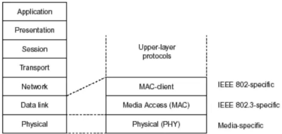
flowchart
graph TD
    A["Application"] --> B["Presentation"]
    B --> C["Session"]
    C --> D["Transport"]
    D --> E["Network"]
    E --> F["Data link"]
    F --> G["Physical"]
    H["Upper-layer protocols"] --> I["MAC-client"]
    I --> J["Media Access (MAC)"]
    J --> K["Physical (PHY)"]
    L["IEEE 802-specific"] --> M["IEEE 802.3-specific"]
    M --> N["Media-specific"]
In the above figure, we can see that Ethernet locates at the Data Link layer and Physical layer and comprises three portions, including logical link control (LLC), media access control (MAC), and physical layer. The first two comprises Data link layer, which performs splitting data into frame for transmitting, receiving acknowledge frame, error checking and re-transmitting when not received correctly as well as provides an error-free channel upward to network layer.

flowchart
graph TD
    A["IEEE 802.2 LLC"] --> B["IEEE802.3 CSMA/CD MAC"]
    B --> C["IEEE 802.3 PLS"]
    B --> D["CS"]
    C --> E["IEEE 802.3 MAU"]
    D --> F["ANSI X3T9.5 PMD"]
    E --> G["Coaxial/STP/UTP"]
    F --> H["Fiber"]
    I["Data Link Layer"] --> A
    J["Physical Layer"] --> C
    K["MII"] --> F
This above diagram shows the Ethernet architecture, LLC sub-layer and MAC sub-layer, which are responded to the Data Link layer, and transceivers, which are responded to the Physical layer in OSI model. In this section, we are mainly describing the MAC sub-layer.
Logical Link Control (LLC)
Data link layer is composed of both the sub-layers of MAC and MAC-client. Here MAC client may be logical link control or bridge relay entity.
Logical link control supports the interface between the Ethernet MAC and upper layers in the protocol stack, usually Network layer, which is nothing to do with the nature of the LAN. So it can operate over other different LAN technology such as Token Ring, FDDI and so on. Likewise, for the interface to the MAC layer, LLC defines the services with the interface independent of the medium access technology and with some of the nature of the medium itself.
| DSAP address | SSAP address | Control | Information |
| 8 bits | 8 bits | 8 or 16 bits | M*8 bits |
| DSAP address | = | Destination service access point address field |
| SSAP address | = | Source service access point address field |
| Control | = | Control field [16 bits for formats that include sequence numbering, and 8 bits for formats that do rot (see 5.2)] |
| Information | = | Information field |
| * | = | Multiplication |
| M | = | An integer value equal to or greater than 0. (Upper bound of M is a function of the medium access control methodology used.) |
The table above is the format of LLC PDU. It comprises four fields, DSAP, SSAP, Control and Information. The DSAP address field identifies the one or more service access points, in which the I/G bit indicates it is individual or group address. If all bit of DSAP is 1s, it's a global address. The SSAP address field identifies the specific services indicated by C/R bit (command or response). The DSAP and SSAP pair with some reserved values indicates some well-known services listed in the table below.
| 0xAAAA | SNAP |
| 0xE0E0 | Novell IPX |
| 0xF0F0 | NetBios |
| 0xFEFE | IOS network layer PDU |
| 0xFFFF | Novell IPX 802.3 RAW packet |
| 0x4242 | STP BPDU |
| 0x0606 | IP |
| 0x9898 | ARP |
LLC type 1 connectionless service, LLC type 2 connection-oriented service and LLC type 3 acknowledge connectionless service are three types of LLC frame for all classes of service. In Fig 3-2, it shows the format of Service Access Point (SAP). Please refer to IEEE802.2 for more details.

text_image
DSAP address field SSAP address field I/G D D D D D D C/R S S S S S S S LED of address Least significant bit Least significant bit of address fields delivered to/ received from the MAC sublayer I/G = 0 Individual DSAP I/G = 1 Group DSAP C/R = 0 Command C/R = 1 Response XODDDDDD DSAP address XOSSSSSS SSAP address X1DDDDDD Reserved for ISO definition X1SSSSSS Reserved for ISO definitionA-2 Media Access Control (MAC)
MAC Addressing
Because LAN is composed of many nodes, for the data exchanged among these nodes, each node must have its own unique address to identify who should send the data or should receive the data. In OSI model, each layer provides its own mean to identify the unique address in some form, for example, IP address in network layer.
The MAC is belonged to Data Link Layer (Layer 2), the address is defined to be a 48-bit long and locally unique address. Since this type of address is applied only to the Ethernet LAN media access control (MAC), they are referred to as MAC addresses.
The first three bytes are Organizational Unique Identifier (OUI) code assigned by IEEE. The last three bytes are the serial number assigned by the vendor of the network device. All these six bytes are stored in a non-volatile memory in the device. Their format is as the following table and normally written in the form as aa-bb-cc-dd-ee-ff, a 12 hexadecimal digits separated by hyphens, in which the aa-bb-cc is the OUI code and the dd-ee-ff is the serial number assigned by manufacturer.
Bit 47 Bit 0
The first bit of the first byte in the Destination address (DA) determines the address to be a Unicast (0) or Multicast frame (1), known as I/G bit indicating individual (0) or group (1). So the 48-bit address space is divided into two portions, Unicast and Multicast. The second bit is for global-unique (0) or locally-unique address. The former is assigned by the device manufacturer, and the later is usually assigned by the administrator. In practice, global-unique addresses are always applied.
A unicast address is identified with a single network interface. With this nature of MAC address, a frame transmitted can exactly be received by the target an interface the destination MAC points to.
A multicast address is identified with a group of network devices or network interfaces. In Ethernet, a many-to-many connectivity in the LANs is provided. It provides a mean to send a frame to many network devices at a time. When all bit of DA is 1s, it is a broadcast, which means all network device except the sender itself can receive the frame and response.
Ethernet Frame Format
There are two major forms of Ethernet frame, type encapsulation and length encapsulation, both of which are categorized as four frame formats 802.3/802.2 SNAP, 802.3/802.2, Ethernet II and Netware 802.3 RAW. We will introduce the basic Ethernet frame format defined by the IEEE 802.3 standard required for all MAC implementations. It contains seven fields explained below.
PRE SFD DA SA Type/Length Data Pad bit if any FCS
7 7 6 6 2 46-1500
4
Preamble (PRE) - The PRE is 7-byte long with alternating pattern of ones and zeros used to tell the receiving node that a frame is coming, and to synchronize the physical receiver with the incoming bit stream. The preamble pattern is:
10101010 10101010 10101010 10101010 10101010 10101010 10101010 10101010
Start-of-frame delimiter (SFD) - The SFD is one-byte long with alternating pattern of ones and zeros, ending with two consecutive 1-bits. It immediately follows the preamble and uses the last two consecutive 1s bit to indicate that the next bit is the start of the data packet and the left-most bit in the left-most byte of the destination address. The SFD pattern is 10101011.
Destination address (DA) - The DA field is used to identify which network device(s) should receive the packet. It is a unique address. Please see the section of MAC addressing.
Source addresses (SA) - The SA field indicates the source node. The SA is always an individual address and the left-most bit in the SA field is always 0.
Length/Type - This field indicates either the number of the data bytes contained in the data field of the frame, or the Ethernet type of data. If the value of first two bytes is less than or equal to 1500 in decimal, the number of bytes in the data field is equal to the Length/ Type value, i.e. this field acts as Length indicator at this moment. When this field acts as Length, the frame has optional fields for 802.3/ 802.2 SNAP encapsulation, 802.3/ 802.2 encapsulation and Netware 802.3 RAW encapsulation. Each of them has different fields following the Length field.
If the Length/ Type value is greater than 1500, it means the Length/ Type acts as Type. Different type value means the frames with different protocols running over Ethernet being sent or received.
For example,
| 0x0800 | IP datagram |
| 0x0806 | ARP |
| 0x0835 | RARP |
| 0x8137 | IPX datagram |
| 0x86DD | IPv6 |
Data - Less than or equal to 1500 bytes and greater or equal to 46 bytes. If data is less than 46 bytes, the MAC will automatically extend the padding bits and have the payload be equal to 46 bytes. The length of data field must equal the value of the Length field when the Length/ Type acts as Length.
Frame check sequence (FCS) - This field contains a 32-bit cyclic redundancy check (CRC) value, and is a check sum computed with DA, SA, through the end of the data field with the following polynomial.
$$ \mathrm{G} (x) = x ^ {3 2} + x ^ {2 6} + x ^ {2 3} + x ^ {2 2} + x ^ {1 6} + x ^ {1 2} + x ^ {1 1} + x ^ {1 0} + x ^ {8} + x ^ {7} + x ^ {5} + x ^ {4} + x ^ {2} + x + 1 $$
It is created by the sending MAC and recalculated by the receiving MAC to check if the packet is damaged or not.
How does a MAC work?
The MAC sub-layer has two primary jobs to do:
- Receiving and transmitting data. When receiving data, it parses frame to detect error; when transmitting data, it performs frame assembly.
- Performing Media access control. It prepares the initiation jobs for a frame transmission and makes recovery from transmission failure.
Frame transmission
As Ethernet adopted Carrier Sense Multiple Access with Collision Detect (CSMA/ CD), it detects if there is any carrier signal from another network device running over the physical medium when a frame is ready for transmission. This is referred to as sensing carrier, also "Listen". If
there is signal on the medium, the MAC defers the traffic to avoid a transmission collision and waits for a random period of time, called backoff time, then sends the traffic again.
After the frame is assembled, when transmitting the frame, the preamble (PRE) bytes are inserted and sent first, then the next, Start of frame Delimiter (SFD), DA, SA and through the data field and FCS field in turn. The followings summarize what a MAC does before transmitting a frame.
- MAC will assemble the frame. First, the preamble and Start-of-Frame delimiter will be put in the fields of PRE and SFD, followed DA, SA, tag ID if tagged VLAN is applied, Ethertype or the value of the data length, and payload data field, and finally put the FCS data in order into the responded fields.
- Listen if there is any traffic running over the medium. If yes, wait.
- If the medium is quiet, and no longer senses any carrier, the MAC waits for a period of time, i.e. inter-frame gap time to have the MAC ready with enough time and then start transmitting the frame.
- During the transmission, MAC keeps monitoring the status of the medium. If no collision happens until the end of the frame, it transmits successfully. If there is a collision happened, the MAC will send the patterned jamming bit to guarantee the collision event propagated to all involved network devices, then wait for a random period of time, i.e. backoff time. When backoff time expires, the MAC goes back to the beginning state and attempts to transmit again. After a collision happens, MAC increases the transmission attempts. If the count of the transmission attempt reaches 16 times, the frame in MAC's queue will be discarded.
Ethernet MAC transmits frames in half-duplex and full-duplex ways. In halfduplex operation mode, the MAC can either transmit or receive frame at a moment, but cannot do both jobs at the same time.
As the transmission of a MAC frame with the half-duplex operation exists only in the same collision domain, the carrier signal needs to spend time to travel to reach the targeted device. For two most-distant devices in the same collision domain, when one sends the frame first, and the second sends the frame, in worstcase, just before the frame from the first device arrives. The collision happens and will be detected by the second device immediately. Because of the medium delay, this corrupted signal needs to spend some time to propagate back to the first device. The maximum time to detect a collision is approximately twice the signal propagation time between the two most-distant devices. This maximum time is traded-off by the collision recovery time and the diameter of the LAN.
In the original 802.3 specification, Ethernet operates in half duplex only. Under this condition, when in 10Mbps LAN, it's 2500 meters, in 100Mbps LAN, it's approximately 200 meters and in 1000Mbps, 200 meters. According to the theory, it should be 20 meters. But it's not practical, so the LAN diameter is kept by using to increase the minimum frame size with a variable-length non-data extension bit field which is removed at the receiving MAC. The following tables are the frame format suitable for 10M, 100M and 1000M Ethernet, and some parameter values that shall be applied to all of these three types of Ethernet.
Actually, the practice Gigabit Ethernet chips do not feature this so far. They all have their chips supported full-duplex mode only, as well as all network vendors' devices. So this criterion should not exist at the present time and in the future. The switch's Gigabit module supports only full-duplex mode.
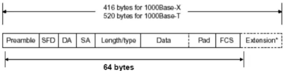
text_image
416 bytes for 1000Base-X 520 bytes for 1000Base-T Preamble SFD DA SA Length/type Data Pad FCS Extension* 64 bytes| Parameter value/LAN | 10Base | 100Base | 1000Base |
| Max. collision domain DTE to DTE | 100 meters 100 meters for UTP412 meters for fiber | 100 meters for UTP316 meters for fiber | |
| Max. collision domain with repeater | 2500 meters 205 meters 200 meters | ||
| Slot time | 512 bit times 512 bit times 512 bit times | ||
| Interframe Gap | 9.6us | 0.96us | 0.096us |
| AttemptLimit | 16 | 16 | 16 |
| BackoffLimit | 10 | 10 | 10 |
| JamSize | 32 bits 32 bits 32 bits | ||
| MaxFrameSize | 1518 | 1518 | 1518 |
| MinFrameSize | 64 | 64 | 64 |
| BurstLimit | Not applicable Not applicable 65536 bits | ||
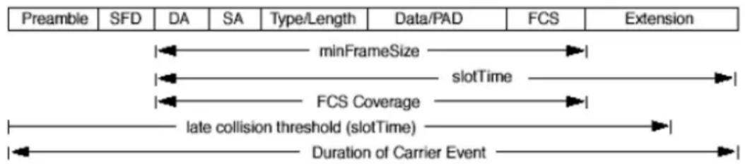
text_image
Preamble SFD DA SA Type/Length Data/PAD FCS Extension minFrameSize slotTime FCS Coverage late collision threshold (slotTime) Duration of Carrier EventIn full-duplex operation mode, both transmitting and receiving frames are processed simultaneously. This doubles the total bandwidth. Full duplex is much easier than half duplex because it does not involve media contention, collision, retransmission schedule, padding bits for short frame. The rest functions follow the specification of IEEE802.3. For example, it must meet the requirement of minimum inter-frame gap between successive frames and frame format the same as that in the half-duplex operation.
Because no collision will happen in full-duplex operation, for sure, there is no mechanism to tell all the involved devices. What will it be if receiving device is busy and a frame is coming at the same time? Can it use “backpressure” to tell the source device? A function flow control is introduced in the full-duplex operation.
A-3 Flow Control
Flow control is a mechanism to tell the source device stopping sending frame for a specified period of time designated by target device until the PAUSE time expires. This is accomplished by sending a PAUSE frame from target device to source device. When the target is not busy and the PAUSE time is expired, it will send another PAUSE frame with zero time-to-wait to source device. After the source device receives the PAUSE frame, it will again transmit frames immediately. PAUSE frame is identical in the form of the MAC frame with a pause-time value and with a special destination MAC address 01-80-C2-00-00-01. As per the specification, PAUSE operation can not be used to inhibit the transmission of MAC control frame.
Normally, in 10Mbps and 100Mbps Ethernet, only symmetric flow control is supported. However, some switches (e.g. 24-Port GbE Web Smart Switch) support not only symmetric but asymmetric flow controls for the special application. In Gigabit Ethernet, both symmetric flow control and asymmetric flow control are supported. Asymmetric flow control only allows transmitting PAUSE frame in one way from one side, the other side is not but receipt-and-discard the flow control information. Symmetric flow control allows both two ports to transmit PASUE frames each other simultaneously.
Inter-frame Gap time
After the end of a transmission, if a network node is ready to transmit data out and if there is no carrier signal on the medium at that time, the device will wait for a period of time known as an inter-frame gap time to have the medium clear and stabilized as well as to have the jobs ready, such as adjusting buffer counter, updating counter and so on, in the receiver site. Once the inter-frame gap time expires after the de-assertion of carrier sense, the MAC transmits data. In IEEE802.3 specification, this is 96-bit time or more.
Collision
Collision happens only in half-duplex operation. When two or more network nodes transmit frames at approximately the same time, a collision always occurs and interferes with each other. This results the carrier signal distorted and undiscriminated. MAC can afford detecting, through the physical layer, the distortion of the carrier signal. When a collision is detected during a frame transmission, the transmission will not stop immediately but, instead, continues transmitting until the rest bits specified by jamSize are completely transmitted. This guarantees the duration of collision is enough to have all involved devices able to detect the collision. This is referred to as Jamming. After jamming pattern is sent, MAC stops transmitting the rest data queued in the buffer and waits for a random period of time, known as backoff time with the following formula. When backoff time expires, the device goes back to the state of attempting to transmit frame. The backoff time is determined by the formula below. When the times of collision is increased, the backoff time is getting long until the collision times excess 16. If this happens, the frame will be discarded and backoff time will also be reset.
$$ 0 \leq r < 2 ^ {k} $$
where
$$ k = \min (n, 1 0) $$
Frame Reception
In essence, the frame reception is the same in both operations of half duplex and full duplex, except that full-duplex operation uses two buffers to transmit and receive the frame independently. The receiving node always "listens" if there is traffic running over the medium when it is not receiving a frame. When a frame destined for the target device comes,
the receiver of the target device begins receiving the bit stream, and looks for the PRE (Preamble) pattern and Start-of-Frame Delimiter (SFD) that indicates the next bit is the starting point of the MAC frame until all bit of the frame is received.
For a received frame, the MAC will check:
- If it is less than one slotTime in length, i.e. short packet, and if yes, it will be discarded by MAC because, by definition, the valid frame must be longer than the slotTime. If the length of the frame is less than one slotTime, it means there may be a collision happened somewhere or an interface malfunctioned in the LAN. When detecting the case, the MAC drops the packet and goes back to the ready state.
- If the DA of the received frame exactly matches the physical address that the receiving MAC owns or the multicast address designated to recognize. If not, discards it and the MAC passes the frame to its client and goes back to the ready state.
- If the frame is too long. If yes, throws it away and reports frame Too Long.
- If the FCS of the received frame is valid. If not, for 10M and 100M Ethernet, discards the frame. For Gigabit Ethernet or higher speed Ethernet, MAC has to check one more field, i.e. extra bit field, if FCS is invalid. If there is any extra bits existed, which must meet the specification of IEEE802.3. When both FCS and extra bits are valid, the received frame will be accepted, otherwise discards the received frame and reports frameCheckError if no extra bits appended or alignmentError if extra bits appended.
- If the length/ type is valid. If not, discards the packet and reports lengthError.
- If all five procedures above are ok, then the MAC treats the frame as good and de-assembles the frame.
What if a VLAN tagging is applied?
VLAN tagging is a 4-byte long data immediately following the MAC source address. When tagged VLAN is applied, the Ethernet frame structure will have a little change shown as follows.
| Pre | SFD | DA | SA | VLAN type ID | Tag control information | Length/ type | Data | Pad | FCS | Ext |
Only two fields, VLAN ID and Tag control information are different in comparison with the basic Ethernet frame. The rest fields are the same.
The first two bytes is VLAN type ID with the value of 0x8100 indicating the received frame is tagged VLAN and the next two bytes are Tag Control Information (TCI) used to provide user priority and VLAN ID, which are explained respectively in the following table.
| Bits 15-13 | User Priority 7-0, 0 is lowest priority |
| Bit 12 | CFI (Canonical Format Indicator)1: RIF field is present in the tag header0: No RIF field is present |
| Bits 11-0 | VID (VLAN Identifier)0x000: Null VID. No VID is present and only user priority is present.0x001: Default VID0xFFFF: Reserved |
Note: RIF is used in Token Ring network to provide source routing and comprises two fields, Routing Control and Route Descriptor.
When MAC parses the received frame and finds a reserved special value 0x8100 at the location of the Length/ Type field of the normal non-VLAN frame, it will interpret the received frame as a tagged VLAN frame. If this happens in a switch, the MAC will forward it, according to its priority and egress rule, to all the ports that is associated with that VID. If it happens in a network interface card, MAC will deprive of the tag header and process it in the same way as a basic normal frame. For a VLAN-enabled LAN, all involved devices must be equipped with VLAN optional function.
At operating speeds above 100 Mbps, the slotTime employed at slower speeds is inadequate to accommodate network topologies of the desired physical extent. Carrier Extension provides a means by which the slotTime can be increased to a sufficient value for the desired topologies, without increasing the minFrameSize parameter, as this would have deleterious effects. Nondata bits, referred to as extension bits, are appended to frames that are less than slotTime bits in length so that the resulting transmission is at least one slotTime in duration. Carrier Extension can be performed only if the underlying physical layer is capable of sending and receiving symbols that are readily distinguished from data symbols, as is the case in most physical layers that use a block encoding/ decoding scheme.
The maximum length of the extension is equal to the quantity (slotTime - minFrameSize). The MAC continues to monitor the medium for collisions while it is transmitting extension bits, and it will treat any collision that occurs after the threshold (slotTime) as a late collision.
Index
A
Account Manager, 142
B
Backup Manager, 140
Bandwidth, 105
C
CoS Mapping, 102
D
Dashboard, 14, 15
Diagnostics, 147, 157
DoS, 76
DoS Port Setting, 78
DoS Protection, 78
E
Egress Shaping Per Queue, 107
Egress Shaping Rate, 106
F
Factory Default, 144
G
General, 88, 91, 96, 98
General Setup, 18
I
Ingress Rate Limit, 105
Installation for VigorAPM, 6
L
License Agreement, 20
License Information, 23, 24, 29, 40, 41, 48, 49, 55
Limiting Rate, 75
P
PoE Configuration, 109
Preamble, 74
Properties, 76
Q
QoS Configuration, 87, 97
S
Security, 59, 73
SNMP, 126
SNMP Community, 129, 130, 132
Storm Control, 75
Storm Control, 60, 74
Storm Control, 79
Stric Priority Queue, 101
System Configuration, 17
System Maintenance, 115
U
Upgrade Manager, 141
W
Weight, 101
WRR Bandwidth, 101