SM-03-642 - Vibrating platform Smart365 - Free user manual and instructions
Find the device manual for free SM-03-642 Smart365 in PDF.

| Product Type | Vibrating Platform |
| Brand | Smart365 |
| Model | SM-03-642 |
| Dimensions (L x W x H) | 60 cm x 40 cm x 15 cm |
| Weight | 15 kg |
| Maximum User Weight | 120 kg |
| Power Supply | AC 220-240V, 50/60 Hz |
| Power Consumption | 120 W |
| Speed Levels | 3 levels |
| Timer Range | 1 - 15 minutes |
| Main Functions | Whole body vibration, muscle toning, blood circulation enhancement |
| Additional Features | Remote control, anti-slip surface |
| Material | Steel frame, ABS plastic housing |
| Color | Black / Silver |
| Maintenance | Wipe with a damp cloth; do not use abrasive cleaners |
| Cleaning | Ensure device is unplugged before cleaning |
| Safety Features | Automatic shut-off, overload protection |
| Spare Parts | Contact customer service for replacement parts |
| Repairability | Repairs should be carried out by a qualified technician |
| General Information | This device is intended for home use only |
Frequently Asked Questions - SM-03-642 Smart365
User questions about SM-03-642 Smart365
0 question about this device. Answer the ones you know or ask your own.
Ask a new question about this device
Download the instructions for your Vibrating platform in PDF format for free! Find your manual SM-03-642 - Smart365 and take your electronic device back in hand. On this page are published all the documents necessary for the use of your device. SM-03-642 by Smart365.
USER MANUAL SM-03-642 Smart365
natural_image
Technical line drawing of a manual lawn mower with black clamps and attached frame (no text or symbols)WIBRACYJNA ZAGĘSZCZARKA PŁYTOWA PLATE COMPACTORS
Read and understand the entire manual before operating machine
SPIS TREŚCI
7. DOSTARCZONE ELEMENTY
natural_image
Mechanical tool with handle and base components, no visible text or symbolsnatural_image
Line drawing of a bicycle seat with a handle and seatbelt, showing no text or symbolsnatural_image
Mechanical diagram of a lever system with two wheels and a handle (no text or symbols)natural_image
Diagram of a vehicle chassis with wheels and a rod, showing directional arrows indicating motion (no text or symbols)natural_image
Technical line drawing of a vehicle chassis with visible mechanical components and directional arrows (no text or symbols)natural_image
Technical line drawing of a mechanical robotic device with articulated joints and base platform (no text or symbols)

natural_image
Technical line drawing of a mechanical pump assembly with no visible text or symbolsnatural_image
Diagram of a mechanical device with a downward arrow pointing to a liquid level, no text or symbols presentnatural_image
Line drawing of a manual lawn mower with a mounted pump and wheels (no text or symbols)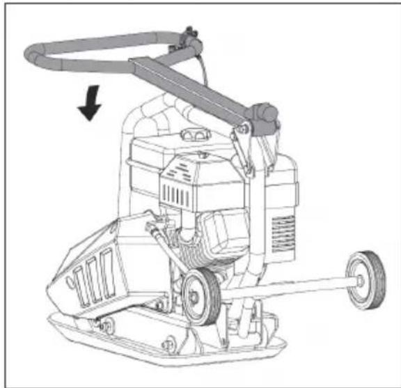
natural_image
Line drawing of a mechanical cleaning or cleaning machine with wheels and a handle (no text or symbols)
natural_image
Technical line drawing of a mechanical pump or lift with attached clamping device (no text or symbols)TABLE OF CONTENTS
- Introduction
- Specifications
- Symbols
- Environmental
- General Safety Rules
- Specific Safety Rules
- Contents supplied
- Assembly
- Know your plate compactor
- Features and Controls
- Before operation
- Operation
- Maintenance
- Storage
- Lifting/Transporting
- Trouble Shooting
- Parts Schedule
1. INTRODUCTION
Your new Vibratory Plate Compactor will more than satisfy your expectations. It has been manufactured under stringent quality standards to meet superior performance criteria. You will find it easy and safe to operate, and with proper care, it will give you many years of dependable service.

Carefully read through this entire operator's manual before using your new Log Splitter. Take special care to heed the cautions and warnings.
2. SPECIFICATION
| Specifications | ||||
| Index SM-03-642 SM-03-65 | SM-03-660 SM-03-665 | |||
| Centrifuga force 11000N 13 | 000N 20000N 25000N | |||
| Plate size 515x390 mm 520 | x445 mm 560x520 mm 32 m/min | |||
| Exciter speed 5500 ud/ min | 5500 ud/ min 5500 ud/ min | 5500 ud/ min | ||
| Travel speed 25 m/min 15m | min 35 m/min 32 m/min | |||
| Compaction depth | 25 cm | 30 cm | 35 cm | 35 cm |
| Net weight | 63 kg | 79 kg | 96 kg | 108 kg |
| Engine | ||||
| Engine model | 18 | 18 | PW200 | PW200 |
| Displacement | 166 cm^3 | 196 cm^3 | 196 cm^3 | 196 cm^3 |
| Power | 6,5KM | 6,5 KM | 6,5 KM | 6,5 KM |
| Fuel | 95 Pb 95 Pb 95 Pb | 95 Pb | ||
2.1 Contents of the box:
- Plate compactor
- Wheels
- Paving pad
- Plate compactor manual
- Engine manual
The commitment to quality has been designed into details: reinforced self-cleaning base plate, engine oil drain hose, closed V-belt guard, self-adjusting centrifugal clutch and folding handle. A range of useful accessories enables use in all kinds of applications.
The Plate Compactor applies energy to the loose soil or other materials to increase its density and load bearing capacity, mainly used for small repair and maintenance work. The loose soil or particles are moved or rearranged in a particular manner close to each other to avoid any trapped air or voids. It increases the load bearing capacity, decreases water seepage, prevents soil settlement, reduces swelling, contraction of the soil and prevents frost damage. It is ideal for compaction of granular soils, sands, gravel, crushed aggregate and mixed soils.

These compactors are not intended to be used on cohesive soils such clay or hard surfaces like concrete.
The Engine Manufacturer is responsible for all engine-related issues with regards to performance, power rating, specifications, warranty and service. Please refer to the Engine Manufacturer's owner/operator's manual, packed separately with your unit, for more information.
3. SYMBOLS
The rating plate on your machine may show symbols. These represent important information about the product or instructions on its use.


Read these instructions for use carefully.
Use safety equipment. Always wear eye and hearing protection, safety footwear, gloves and helmets.
It is forbidden to remove or tamper with the protection devices and safety devices.
Keep away from rotating parts.
Do not smoke or have open flames. Use extreme caution when storing, handling and using fuels, as they are highly volatile and explosive in vapor state.
Do not touch parts which are hot from operation. Serious burns may result.
Keep children and bystanders off and away.
4. ENVIRONMENTAL

Recycle unwanted materials instead of disposing of them as waste. All tools, hoses and packaging should be resor ted, taken to the local recycling
center and disposed of in an environmentally safe way.
5. GENERAL SAFETY RULES
Understand your machine
- Read and understand the operator's manual and labels affixed to the machine. Learn its application and limitations as well as the specific potential hazards peculiar to it.
- Be thoroughly familiar with the controls and their proper operation. Know how to stop the machine and disengage the controls quickly.
- Make sure to read and understand all the instructions and safety precautions as outlined in
the Engine Manual, packed separately with your unit. Do not attempt to operate the machine until you fully understand how to properly operate and maintain the Engine and how to avoid accidental injuries and/or property damage.
Work area
- Never start or run the engine inside a closed area. The exhaust fumes are dangerous, containing carbon monoxide, an odorless and deadly gas. Operate this unit only in a well ventilated outdoor area.
- Never operate the machine without good visibility or light.
Personal safety
- Do not operate the machine while under the influence of drugs, alcohol, or any medication that could affect your ability to use it properly.
- Dress properly. Wear heavy long pants, boots and gloves. Do not wear loose clothing, short pants, jewelry of any kind. Secure long hair so it is above shoulder level. Keep your hair, clothing and gloves away from moving parts. Loose clothes, jewelry or long hair can be caught in moving parts.
- Check your machine before starting it. Keep guards in place and in working order. Make sure all nuts, bolts, etc. are securely tightened.
- Never operate the machine when it is in need of repair or is in poor mechanical condition. Replace damaged, missing or failed parts before using it. Check for fuel leaks. Keep the machine in safe working condition.
- Do not use the machine if the engine's switch does not turn it on or off. Any gasoline powered machine that can not be controlled with the engine switch is dangerous and must be replaced.
- Form a habit of checking to see that keys and adjusting wrenches are removed from machine area before starting it. A wrench or a key that is left attached to a rotating part of the machine may result in personal injury.
- Stay alert, watch what you are doing and use common sense when operating the machine.
- Do not overreach. Do not operate the machine while barefoot or when wearing sandals or similar lightweight footwear. Wear protective footwear that will protect your feet and improve your footing on slippery surfaces. Keep proper footing and balance at all times. This enables better control of the machine in unexpected
situations.
- Avoid accidental starting. Be sure the engine's switch is off before transporting the machine or performing any maintenance or service on the unit. Transporting or performing maintenance or service on a machine with its switch on invites accidents.
Fuel safety
- Fuel is highly flammable, and its vapors can explode if ignited. Take precautions when using to reduce the chance of serious personal injury.
- When refilling or draining the fuel tank, use an approved fuel storage container while in a clean, well-ventilated outdoor area. Do not smoke, or allow sparks, open flames or other sources of ignition near the area while adding fuel or operating the unit. Never fill fuel tank indoors.
- Keep grounded conductive objects, such as tools, away from exposed, live electrical parts and connections to avoid sparking or arcing. These events could ignite fumes or vapors.
- Always stop the engine and allow it to cool before filling the fuel tank. Never remove the cap of the fuel tank or add fuel while the engine is running or when the engine is hot. Do not operate the machine with known leaks in the fuel system.
- Loose the fuel tank cap slowly to relieve any pressure in the tank.
- Never overfill fuel tank (there should be no fuel above the upper limit mark).
- Replace all fuel tank and container caps securely and wipe up spilled fuel. Never operate the unit without the fuel cap securely in place.
- Replace all fuel tank and container caps securely and wipe up spilled fuel. Never operate the unit without the fuel cap securely in place.
- Avoid creating a source of ignition for spilled fuel. If fuel is spilled, do not attempt to start the engine but move the machine away from the area of spillage and avoid creating any source of ignition until fuel vapors have dissipated.
- Store fuel in containers specifically designed and approved for this purpose.
- Store fuel in a cool, well-ventilated area, safely away from sparks, open flames or other sources of ignition.
- Never store fuel or machine with fuel in the tank inside a building where fumes may reach an spark, open flame, or any other source of ignition, such as a water heater, furnace, clothes dryer and the like. Allow the engine to cool before storing in any enclosure.
Machine use and care
- Never pick up or carry a machine while the engine is running.
- Do not force the machine. Use the correct machine for your application. The correct machine will do the job better and safer at the rate for which it was designed.
- Do not change the engine governor settings or over -speed the eng in e. The g ov ern or controls the maximum safe operating speed of the engine.
- Do not run the engine at a high speed when you are not pounding.
- Do not put hands or feet near rotating parts. Avoid contact with hot fuel, oil, exhaust fumes and hot surfaces. Do not touch the engine or muffler. These parts get extremely hot from operation. They remain hot for a short time after you turn off the unit. Allow the engine to cool before doing maintenance or making adjustments.
- If the machine should start to make an unusual noise or vibration, immediately shut off the engine, disconnect the spark plug wire, and check for the cause. Unusual noise or vibration is generally warning of trouble.
- Use only attachments and accessories approved by the manufacturer. Failure to do so can result in personal injury.
- Maintain the machine. Check for misalignment or binding of moving parts, breakage of parts and any other condition that may affect the machine's operation. If damaged, have the machine repaired before use. Many accidents are caused by poorly maintained equipment.
- Keep the engine and muffler free of grass, leaves, excessive grease or carbon build up to reduce the chance of a fire hazard.
- Never douse or squirt the unit with water or any other liquid. Keep handles dry, clean and free from debris. Clean after each use.
- Observe proper disposal laws and regulations for gas, oil, etc. to protect the environment.
- Store idle machine out of the reach of children and do not allow persons unfamiliar with the machine or these instructions to operate it. Machine is dangerous in the hands of untrained users.
Service
- Before cleaning, repair, inspecting, or adjusting, shut off the engine and make certain all moving parts have stopped. Always make sure the engine's switch is in its "OFF" position. Disconnect the spark plug wire, and keep the wire away from the plug to prevent accidental starting.
- Have your machine serviced by a qualified repair
personnel using only identical replacement parts. This will ensure that the safety of the machine maintained.
6. SPECIFIC SAFETY RULES
• To avoid injury, keep hands, fingers and feet away from the base plate. Grip the handle of the plate compactor firmly with both hands. If both hands are holding the handle and your feet are clear of the compactor base, your hands, fingers and feet can not be injured by the compactor base.
• Always operate the machine from behind, GB never pass or stand in front of the machine when the engine is running.
- Never place tools or any other item under the plate compactor.
- If the unit strikes a foreign object, stop the engine, disconnect the spark plug, thoroughly inspect the machine for any damage, and repair the damage before restarting and operating the machine.
- Do not overload the machine capacity by compacting too deep in a single pass or at too fast a rate.
- Never operate the unit at high transport speeds on hard or slippery surfaces.
- Exercise extreme caution when operating on or crossing gravel drives, walks, or roads. Stay alert for hidden hazards or traffic. Do not carry passengers.
- Never leave the operating position and leave the plate compactor unattended when the engine is running.
• Always stop the engine when compacting is delayed or when walking from one location to another.
- Stay away from the edged of ditches and avoi d actions that may cause the plate compactor to topple over.
• Always ascend slopes carefully, in a direct path and in reverse to present the plate compactor from toppling over onto the operator.
• Always park the unit on a firm and level surface and shut the tool off.
- To reduce exposure to vibration, limit the hours of operation and take periodic breaks to minimize repetition and rest your hand. Reduce the speed and force in which you do the repetitive movement. Try to fill each day with jobs where operating hand-held power equipment is not required.
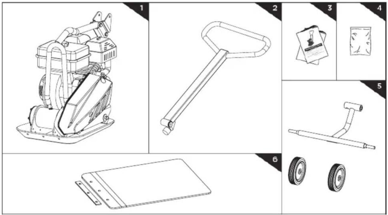
7. CONTENTS SUPPLIED
The plate compactor comes partially assembled 4 and is shipped in carefully packed carton. After all the parts have been removed from the carton, you should have:
- Plate Compactor Chassis with Engine and Transmission
- Handle
- Operator's Manual & Engine Manual
- Hardware Bag, Including:
- Folding Wheels Bracket
- Paving Pad
8. ASSEMBLY
Following the assembly directions below, you will assemble the plate compactor in a few minutes.
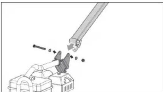
natural_image
Mechanical assembly diagram showing a lever interacting with a clamp and base (no text or symbols)- Mount the handle to the chassis with the M10X90 bolt, washers and nut.
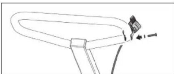
natural_image
Line drawing of a bicycle seat with a handle and seatbelt, showing no text or symbols- Unscrew bolt 5 x 35 from throttle control. Secure the Throttle Control onto the Upper Handle with a flat washer 5 and the bolt 5 x 35 that just were unscrewed.
Folding Wheels Kit
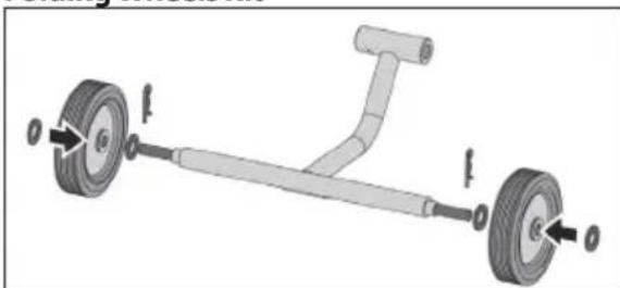
natural_image
Mechanical diagram of a wheeled cart with two wheels and a handle, showing force application (no text or symbols)-
Slide the wheels over the stub axles. Secure with hairpin retainers and flat washers.
-
Pull out the pin first, adjust the wheels to the suitable distance, then tighten with the pin.
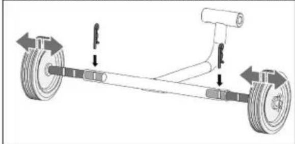
natural_image
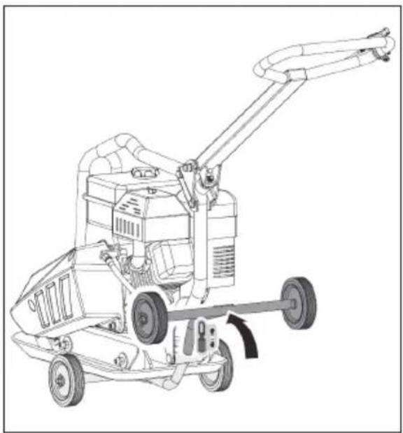
Diagram of a vehicle chassis with wheels and a lever, showing directional arrows indicating motion (no text or symbols)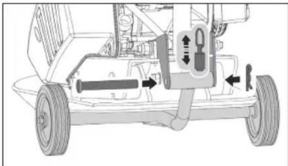
natural_image
Technical line drawing of a vehicle chassis with labeled components (no text or symbols)- Pull up the spring bolt and put the upper pipe of the wheels bracket into the mounting bracket. Align two ends of the pipe with the holes. Slide the bolt in and secure with the clips.
Paving Pad Kit
- The transparent rubber Paving Pad allows to compact concrete paving slabs, stones, bricks and blocks silently and gently.
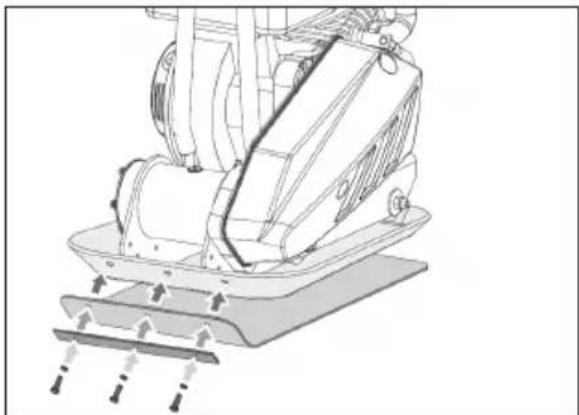
natural_image
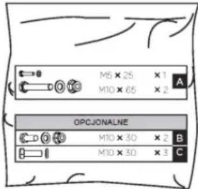
Technical line drawing of a mechanical device with mounting base and clamping elements (no text or symbols)- Attach the Paving Pad onto the Base Plate as shown. Align the holes in the Base Plate, Paving Pad and Clamp Plates, and secure it with 3 bolts M10x25 and lock washers
Engine Oil

OIL HAS BEEN DRAINED FOR
SHIPPING. Failure to fill engine sump with oil before starting engine will result in permanent damage and void
engine warranty.
Add oil according to Engine Manual packed separately with your tiller.
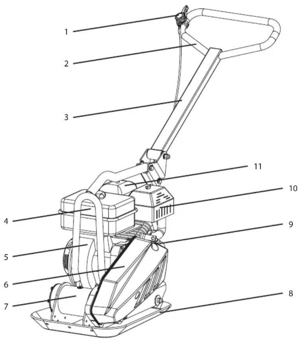
9. KNOW YOUR PLATE COMPACTOR
EN
- Throttle Control
- Lift Handle
- Handle
- Fuel Tank
- Engine
- Belt Guard
- Exciter
- Base Plate
- Oil Drain Hose
- Muffler
- Air Cleaner
Fuel Valve Control
The fuel valve opens and closes the passage between the fuel tank and the carburetor. The fuel valve lever must be in the ON position for the engine to run. When the engine is not in use, leave the fuel valve lever in the OFF position to prevent carburetor flooding and to reduce the possibility of fuel leakage.
Throttle Control
The throttle lever controls engine speed. Moving the throttle lever makes the engine run faster or slower.
Engine Switch
The engine switch enables and disables the ignition system. The engine switch must be in the ON
position for the engine to run. Turning the engine switch to the OFF position stops the engine.
Choke Lever
The choke lever opens and closes the choke valve in the carburetor. The closed position enriches the fuel mixture for starting a cold engine. The open position provides the correct fuel mixture for operation after starting, and for restarting a warm engine. Some engine applications use a remotely-mounted choke control rather than the engine-mounted choke lever.
Recoil Starter Grip
Pulling the starter grip operates the recoil starter to crank the engine.
Oil Drain Hose
Running the engine with dirty oil can cause premature engine wear and failure. Changing oil regularly is extremely important. The flexible oil drain hose is equipped to drain oil into appropriate receptacle.
Choke Lever
Running the engine with dirty oil can cause premature engine wear and failure. Changing oil regularly is extremely important. The flexible oil drain hose is equipped to drain oil into appropriate receptacle.
Exciter
An eccentric weight mounted on the exciter shaft contained within exciter housing is driven at high speed by a clutch and belt drive system. This high speed shaft revolution causes the rapid lifting and downward ramming motion of the machine as well as imparting a forward motion.
10. BEFORE OPERATION
This machine is intended to be used for compacting friable soil (rushed stone ratio<30%). It can be used wildly in highway, construction, dam, airport, railway and so on. It can offer them a solid soil basis.

It cannot be used in the following areas: solid or sharp surface like cement ground, stone and so on, or it will make the rammer damage.
Manufacturer does not assume responsibility for any accident due to equipment modifications.
Check before work
- Add the engine oil: Make sure the machine with engine stands vertically. remove the oil dipstick, then add the engine oil, insert the dipstick into the oil tank to check the oil level, if the oil lever comes near to the lower limit mark, refill the oil tank up to the upper limit mark. Engine oil capacity is 0.6L
- Check the impact system lubricating oil level, fill the oil to the upper location of the oil window.

Oil recommended: generally SAE10W-30 is recommended, as it is suitable to the common environment temperature. If choose other ones, It will short the work life if use the oil lack of detersive or the oil for two- stroke engine.
- Check the air cleaner: check whether the filteris blocked and sponge is broken; dirty filter willblock the air cleaner, which will weaken theengine even make the engine fail to start.
- Make sure all the screws are tightened.
- Check the fuel tank: the fuel must be above 90#lead-free gasoline. The recommended fuel is above 93# lead-free gasoline. Do not get dust, water or other foreign matter into the fuel tank, do not mix the fuel with engine oil.

Never fill fuel tank while operating theunit.
Fill the fuel tank as instructed in the separate Engine Manual packed with the Plate Compactor. More detailed description of the engine operation and all related precautions and procedures can be found in the Engine Manual packed separately with the unit.
Starting Engine
- Move the fuel valve lever to the ON position.
- To start a cold engine, move the choke to the CLOSE position. To restart a warm engine, leave the choke lever in the OPEN position.
- Move the throttle lever away from the SLOW position, about 1/3 of the way toward the FAST position.
- Turn the engine switch to the ON position.
- Operate the starter.
Operating

Do not operate plate on concrete or on extremely hard, dry, compacted surfaces. The plate will jump rather than vibrate and could damage both
plate and engine.
- After engine warms up, pull throttle lever to accelerate engine speed. Plate will begin vibrating and move forward.
- The plate compactor is designed to run at an engine speed (engine take off shaft) of 3600 rpm (Normally considered full throttle). Running the engine at lower rpm's will result in a decrease of compaction force and lower travel speed. It will create excessive "out-of-synch" vibrations resulting in poor compaction, maneuverability, excessive wear to the machine, and discomfort to the operator.
- In operation, guide the machine, but let the compactor do the work. Bearing down on the handle is unnecessary and causes shock absorber wear.
- On level surfaces the compactor moves forward rapidly. On uneven surfaces or inclines, light forward pressure on handle may be required to assist the compactor in moving forward.
- The number of passes required to reach a desired compaction level will depend on the type and moisture content of soil. Maximum soil compaction has been reached when excessive kickback is noticed.

When using a compactor on asphalt, Water Sprinkler Kit is required to help prevent the bottom plate from adhering to the hot asphalt surface. When using plate on paving stones, attach a pad to the bottom of the plate to prevent chipping or grinding surface of the stones.
A special urethane pad designed for this purpose is available as an optional accessory.

While a certain amount of moisture in the soil is necessary, excessive moisture may cause soil particles to stick together and prevent good compaction. If soil is extremely wet, allow it to dry somewhat before compacting.

If soil is so dry as to create dust clouds while operating plate, some moisture should be added to the ground material to improve compacting. This will also reduce service to the air filter.
Stopping Engine
To stop the engine in an emergency, simply turn the engine switch to the OFF position. Under normal conditions, use the following procedure:
- Move the throttle lever to the SLOW position.
- Let engine idle for one or two minutes.
- Turn the engine switch to the OFF position.
- Turn the fuel valve lever to the OFF position.

Do not move choke control to CLOSE to stop engine. Backfire or engine damage may occur.
Idle Speed
Set throttle control lever to its "low" position to reduce stress on the engine when compacting is not being performed. Lowering the engine speed to idle the engine will help extend the life of the engine, as well as conserve fuel and reduce the noise level of the machine.
12. MAINTENANCE
Maintaining your compactor will insure long life to the machine and its components.
Preventive Maintenance
- Turn off engine. Engine must be cool.
- Keep the engine's throttle lever in its SLOW position, and remove spark plug wire from spark plug and secure.
- Inspect the general condition of the plate
compactor. Check for loose screws, misalignment or binding of moving parts, cracked or broken parts, and any other condition that may affect its safe operation.
-
Remove all debris from the plate compactor with a soft brush, vacuum, or compressed air. Then use a premium quality lightweight machine oil to lubricate all moving parts.
-
Clean the bottom of the compactor base as soon as it begins to pick up soil being compacted. The unit can not do a good job if the bottom surface is not smooth and clean.
-
Replace spark plug wire.

Never use a "pressure washer" to clean your plate compactor. Water can penetrate tight areas of the unit and cause damage to spindles, pulleys,
bearings, or the engine. The use of pressure washers will result in shortened life and reduce serviceability.
Checking V-Belt(s)
To ensure optimum power transmission from the engine to the eccentric shaft, the V-belt(s) must be in good condition and operate under proper tension.
-
Turn off engine. Engine must be cool.
-
Remove the belt guard to access the V-belt(s).
-
Check the condition of the V-belt(s). If any V-belt is cracked, frayed, or glazed, it should be replaced as soon as convenient.
-
Check the V-belt tension by squeezing them in the center. The normal deflection on each side should be 9mm 3/8" to 13mm 1/2" with moderate pressure from your thumb or finger.

On new machines or after installing a new belt, check belt tension after first 20 hours of operation. Check and adjust belt every 50 hours
thereafter.
Tensioning V-Belt(s)
Proper belt tension is critical to good performance. Proper adjustment will assure long belt life. Too much or too little belt tension will cause premature belt failure.
- If the plate compactor you bought is with water tank, please pull the water tank up from the chassis as shown.
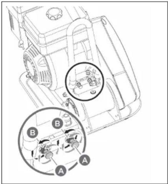
-
Loosen the jam nuts B, leaving enough space between the nut and bracket.
-
Push engine toward the back of the plate by turning the adjustment bolts A to remove any slack in V-belt(s).
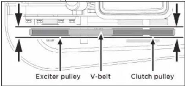

When adjusting the belt(s), make sure that the clutch pulley is in alignment with exciter pulley.
-
JWhen the V-belt tension is correct, tighten the jam nuts B against the bracket.
-
Tighten the engine mount bolts.
-
Replace the belt guard.

If the adjustment bolts have no more adjustment left, the belt(s) may have to be replaced.
Replacing V-Belt(s)

Both V-belts should be replaced at the same time because they will wear evenly through normal use. Work on one belt at a time.
-
Loose 4 engine mount bolts (do not remove) only enough to move the engine forward.
-
Loosen the jam nuts B and bolts A shown B in above figure.
-
Slide the engine toward the front of plate and slip the old V-belt(s) off of the wheel pulley and install the new V-belt(s) in their place.
-
Position the V-belt(s) over the engine pulley.
- Move the engine back.
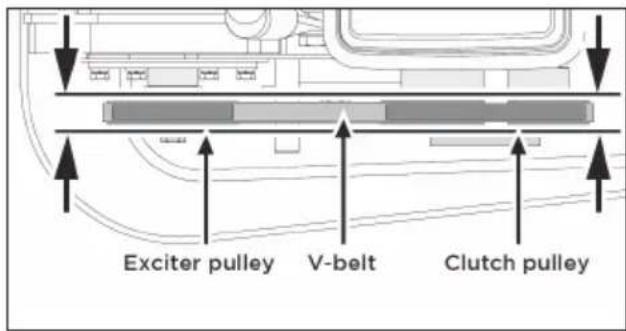

When adjusting the belt(s), make sure that the clutch pulley is in alignment with exciter pulley.
- When the V-belt tension is correct, tighten the jam nuts B and the engine mount bolts.
- Replace the belt guard.

When removing or installing the drive belt(s), be careful not to get your fingers caught between the belt and pulley.
Exciter Lubrication
The exciter housing is pre-serviced using Automatic Transmission Fluid Dextron III, Mercon, EXXON (ESSO) NUTO H-32 or its equivalent. Change fluid after 200 hours of operation.
- Let exciter cool before changing exciter oil.
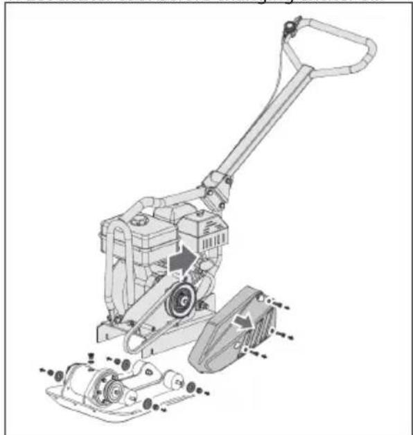
natural_image
Technical line drawing of a manual lawn mower assembly (no text or labels)- Remove the belt guard and V-belt(s).
- Remove the bolts that hold the deck to the housing.
- Lift entire deck with engine from housing.
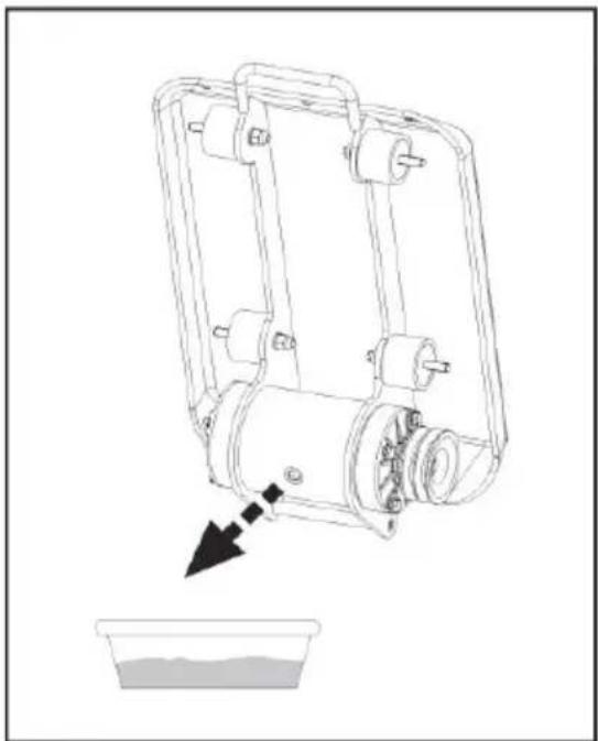
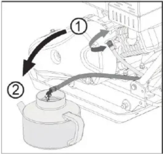
natural_image
Line drawing of a mechanical device with a downward arrow pointing to a liquid level, no text or symbols present.- Remove pipe plug from top of exciter housing. Tilt housing upside down so oil drains from exciter. Examine oil for metal chips as a precaution to future problems.
- Return plate housing to the upright position.
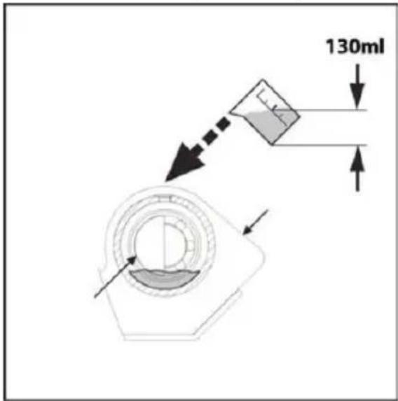
- Fill the exciter housing with exciter oil.

Do not overfill - overfilling can result in excessive temperatures in the exciter.
- Apply pipe sealant to pipe plug and reinstall into top of exciter housing.
- Reinstall deck, V-belt(s) and belt guard.
Engine maintenance
Refer to the Engine Manual included in your plate compactor for the information on engine
maintenance. Your engine manual provides detailed information for performing the tasks.
13. STORAGE
If the plate compactor will not be used for a period longer than 30 days, following the steps below to prepare your unit for storage.
- Drain the fuel tank completely. Stored fuel containing ethanol or MTBE can start to go stale in 30 days. Stale fuel has high gum content and can clog the carburetor and restrict fuel flow.
- Start the engine and allow it to run until it stops. This ensures no fuel is left in the carburetor. Run the engine until it stops. This helps prevent deposits from forming inside the carburetor and possible engine damage.
- While the engine is still warm, drain the oil from the engine. Refill with fresh oil of the grade recommended in the Engine Manual.
- Allow the engine to cool. Remove the spark plug and put 60 ml of SAE-30 of high quality motor oil into the cylinder. Pull the starter rope slowly to distribute the oil. Replace the spark plug.

Remove the spark plug and drain all of the oil from the cylinder before attempting to start the unit after storage.
- Use clean cloths to clean off the outside of the compactor and to keep the air vents free of obstructions.

Do not use strong detergents or petroleum based cleaners when cleaning plastic parts. Chemicals can damage plastics.
- Carefully fold the ? handle down. Do not allow control cables to become pinched or bent.
- Store your plate compactor in upright position in a clean, dry building that has good ventilation.
natural_image
Line drawing of a manual harvester with wheels and a handle, showing mechanical components and motion direction (no text or symbols)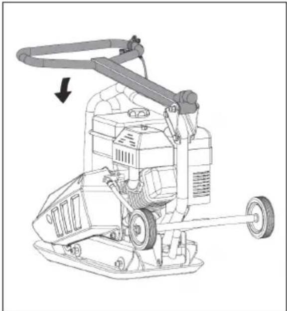
natural_image
Technical line drawing of a mechanical cleaning or cleaning machine with no visible text or symbolsThe unit must be transported in the upright position to prevent fuel from spilling. Do not lay machine on its side or top. Secure or tie down unit using the lifting handle to prevent machine from sliding or tipping over.

Machine may fall and cause damage or injury if lifted incorrectly. Lift using handles at base of plate.
14. LIFTING/TRANSPORTING
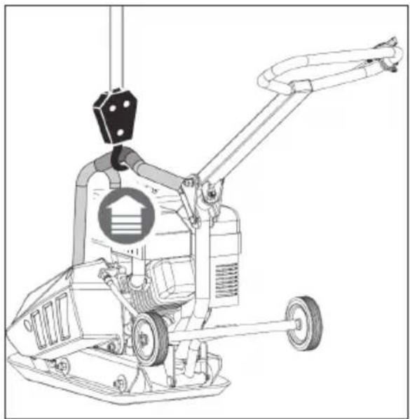
Lifting
See technical data for the weight of the machine. To avoid burns or fire hazards, let engine cool before lifting / transporting machine or storing indoors.
natural_image
Technical line drawing of a mechanical pump or scrubber with attached clamping device (no text or symbols)The unit must be transported in the upright position to prevent fuel from spilling. Do not lay machine on its side or top. Secure or tie down unit using the lifting handle to prevent machine from sliding or tipping over.

Machine may fall and cause damage or injury if lifted incorrectly. Lift using handles at base of plate.
- TROUBLE SHOOTING
| PROBLEM CAUSE REMEDY | ||
| Engine fails Look Engine Instruction | Look Engine Instruction | |
| Upright rammer is difficult to control whenpounding (machinejumps or lurches | Too high engine speed on hardground. | Set the throttle lever at lower speed. |
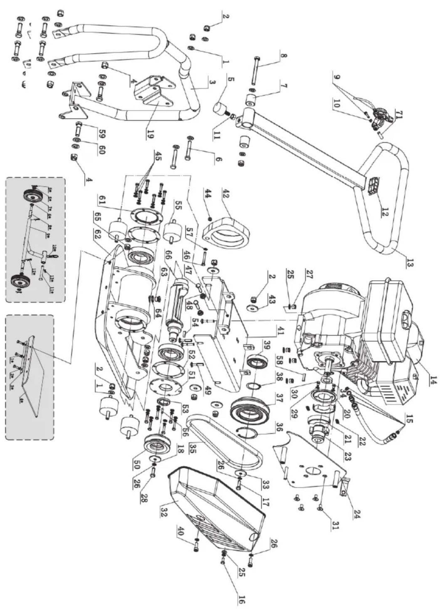
| No. DESCRIPTION Q'TY | |
| PAVING PAD KIT | |
| FOLDING WHEELS KIT | |
| No. DESCRIPTION Q'TY | |
| 1. Washer 10 to | |
| 2. Nut M107 | |
| 3. Lower Handle 1 | |
| 4. Lower Operation Handle Wellment 1 | |
| 5. Shock Absorber 1 | |
| 6. Bolt M10X60 2 | |
| 7. Rubber Sleeve 2 | |
| 8. Bolt M10X90 1 | |
| 9. Trothe Lever 1 | |
| 10. Washer 5 1 | |
| 11. Nut M10 1 | |
| 12. Bidot M8X55 2 | |
| 13. Upper Handle 1 | |
| 14. Engine 2.8HP | 1 |
| 15. Hose | 1 |
| 16. Bolt M8X16 1 | |
| 17. Bolt M6X25 1 | |
| 18. Bolt M10X30 2 | |
| 19. Connector | 1 |
| 20. Nut M10 2 | |
| 21. Flyweight & Friction Disk | 4 |
| 22. Fly Weight Spring | 2 |
| 23. Shaft for Chuck Pullley | 1 |
| 24. Belt Cover Assemblying Plate | 1 |
| 25. Washer 8 9 | |
| 26. Washer B 4 | |
| 27. Nut MB | 6 |
| 28. Bolt M8X25 1 | |
| 29. Bolt M10X30 2 | |
| 30. Washer 10 | |
| 31. Screw M8X16 | 4 |
| 32. Belt Cover | 1 |
| 33. Small Pulley Plate | 1 |
| 34. Bolt M8X20 2 | |
| 35. V-Belt | 1 |
| 36. Circlip 55 1 | |
| 37. Clickth Pulley | 1 |
365 SMART
NO/NR SM-03-642
EC /EU DECLARATION OF CONFORMITY DEKLARACJA ZGODNOŚCI WE/ UE
We hereby declare, that all major safety requirements, concerning to:
CE Machinery Directives [2006/42/EC],
EMC Directives [2004/108/WE, 2014/30/UE],
The outdoor noise derectives [2000/14/EC 2005/88/EU]
are fulfilled, as laid out in the guideline set down by the member states of the EEC Commission.
The standards relevant for the evaluation of safety and EMC requirements are as follows:
TÜV SÜD Certification and Testing (China) Co., Ltd. Shanghai Branch
3-13F, No. 151 Heng Tong Road
Shanghai 200070, P.R.China
We hereby declare, that all major safety requirements, concerning to:
CE Machinery Directives [2006/42/EC],
EMC Directives [2004/ 108/WE, 2014/30/UE],
The outdoor noise derectives [2000/14/EC 2005/88/EU]
are fulfilled, as laid out in the guideline set down by the member states of the EEC Commission.
The standards relevant for the evaluation of safety and EMC requirements are as follows:
TÜV SÜD Certification and Testing (China) Co., Ltd. Shanghai Branch
3-13F, No. 151 Heng Tong Road
Shanghai 200070, P.R.China
We hereby declare, that all major safety requirements, concerning to:
CE Machinery Directives [2006/42/WE],
EMC Directives [2004/ 108/WE, 2014/30/UE],
The outdoor noise derectives [2000/14/EC 2005/88/EU]
are fulfilled, as laid out in the guideline set down by the member states of the EEC Commission.
The standards relevant for the evaluation of safety and EMC requirements are as follows:
Measured sound power level LWA: 102 dB(A)
Guaranteed sound power level LWA: 104 dB(A)
TÜV SÜD Certification and Testing (China) Co., Ltd. Shanghai Branch
3-13F, No. 151 Heng Tong Road
Shanghai 200070, P.R.China
We hereby declare, that all major safety requirements, concerning to:
CE Machinery Directives [2006/42/WE],
EMC Directives [2004/ 108/WE, 2014/30/UE],
The outdoor noise derectives [2000/14/EC 2005/88/EU]
are fulfilled, as laid out in the guideline set down by the member states of the EEC Commission.
The standards relevant for the evaluation of safety and EMC requirements are as follows:
TÜV SÜD Certification and Testing (China) Co., Ltd. Shanghai Branch
3-13F, No. 151 Heng Tong Road
Shanghai 200070, P.R.China
Erpatech provides a warranty for correct operation of the tool.
The warranty period begins from the date of handing over to the user and lasts 12 months, while the consumer warranty (purchase with receipt) lasts 24 months.
All faults resulting from manufacturing or material defects are covered with free repairs.
The warranty does not cover defects resulting from mechanical damages caused by the user, misuse, incorrect maintenance, use of incorrect accessories and defects resulting from overloading of the device.
The warranty is valid if the tool is delivered to the service center without any modifications, with warranty card stamped and signed by the point of sale, with entered index and serial number, with description of the defects, data of purchaser and proof of purchase in form of the receipt or copy of the invoice (with the same date of sale as in the warranty card).
Erpatech. agrees to repair the device within 14 days from the date of delivery to the service center.
All costs related to the provision of safe packaging, insurance and against other risks shall be borne by the Customer.
the defect or due to the high costs of such repair. If the same product is not achievable, then it may be required to deliver new product, with parameters which are not worse then the original.
Decision of the warranty service concerning the justness of notified defects is final.
The warranty does not cover:
- malfunction or damages caused by misuse or improper use not conforming the service manual or safety regulations;
- malfunction or damages caused by overloading of the tool leading to damages of motor, transmission or the other components and by use of the other equipment that recommended;
- mechanical damages of the product and defects caused by them
- malfunction or damages caused as a result of fire, flood or other natural disasters, corrosion or other external impacts;
- products with damaged warranty seals or repaired by the third party service centers or modified in any other way;
- consumable equipment included in the device such as: drill bits, disks, screwdriver bits, tips, knives for planers, blades, abrasive paper and other components subject to wear and tear.
365 SMART
KARTA GWARANCYJNA
Nazwa produktu ....
Numer seryjny ....
Data sprzedaży ....