AR12AGHQAWKXST - Wall mount SAMSUNG - Free user manual and instructions
Find the device manual for free AR12AGHQAWKXST SAMSUNG in PDF.

| Product Type | Wall-Mounted Split Air Conditioner |
| Model | AR12AGHQAWKXST |
| Cooling Capacity (BTU) | 12,000 BTU/h |
| Heating Capacity (BTU) | 12,000 BTU/h (Heat pump model) |
| Indoor Unit Dimensions (W x H x D) | 900 x 300 x 200 mm |
| Outdoor Unit Dimensions (W x H x D) | 700 x 500 x 300 mm |
| Indoor Unit Weight | 10 kg |
| Outdoor Unit Weight | 30 kg |
| Power Supply | 220-240 V, 50 Hz, 1 Ph |
| Refrigerant | R32 |
| Energy Efficiency Rating | A++ |
| Airflow (High Speed) | 500 m³/h |
| Noise Level Indoor (Low/High) | 25 / 40 dB(A) |
| Noise Level Outdoor | 50 dB(A) |
| Remote Control | Yes, included |
| Timer Function | Yes, 24-hour on/off |
| Filter Type | Washable fine dust filter |
| Filter Cleaning Interval | Every 2 weeks |
| Self-Diagnosis | Yes, with error code display |
| Auto Restart | Yes |
| Defrost Function | Yes |
| Installation Type | Wall-mounted with included bracket kit |
| Warranty | 2 years (parts and labor) |
Frequently Asked Questions - AR12AGHQAWKXST SAMSUNG
User questions about AR12AGHQAWKXST SAMSUNG
0 question about this device. Answer the ones you know or ask your own.
Ask a new question about this device
Download the instructions for your Wall mount in PDF format for free! Find your manual AR12AGHQAWKXST - SAMSUNG and take your electronic device back in hand. On this page are published all the documents necessary for the use of your device. AR12AGHQAWKXST by SAMSUNG.
USER MANUAL AR12AGHQAWKXST SAMSUNG
AR09AGHQAWKNST AR09AGHQAWKXST AR12AGHQAWKNST AR12AGHQAWKXST AR18AGHQAWKNST AR18AGHQAWKXST AR24AGHQAWKNST AR24AGHQAWKXST
SERVICE
Manual
AIR CONDITIONER
AR09AGHQAWKNST AR12AGHQAWKNST AR18AGHQAWKNST AR24AGHQAWKNST
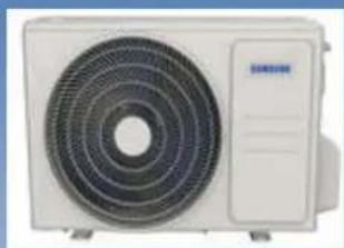
natural_image
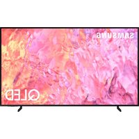
Front view of a white air conditioner unit with concentric fan blades (no visible text or symbols)AR09AGHQAWKXST AR12AGHQAWKXST AR18AGHQAWKXST AR24AGHQAWKXST
CONTENTS
- Precautions
- Product Specifications
- Alignment and Adjustments
- Disassembly and Reassembly
- Wiring Diagram
- PCB Diagram
- Operating Instructions
- Troubleshooting
- Reference Sheet
Contents
1. Precautions 1-1
1-1 In case of accidents or emergency 1-1
1-2 Pre-installation and installation 1-1
1-3 Operation and Maintenance 1-1
1-4 Information servicing(for flammable materials) 1-2
2. Product Specifications 2-1
2-1 The Feature of Product 2-1
2-2 Product Specifications 2-2
2-3 Accessories 2-6
3. Alignment and Adjustments 3-1
3-1 Checking before use 3-1
3-2 Display Error and Check Method 3-2
3-3 Checking the remote controller 3-3
4. Disassembly and Reassembly 4-1
4-1. Indoor Unit 4-2
4-2. Outdoor Unit 4-16
5. Wiring Diagram 5-1
5-1 Indoor Unit 5-2
5-2 Outdoor Unit 5-4
Contents
6. PCB Diagram 6-1
6-1 Indoor Main PCB 6-1
6-2 Display PCB 6-3
7. Operating Instructions 7-1
7-1 Name of Each Part 7-1
7-2 Wireless Remote Control-Buttons and Display 7-2
8. Troubleshooting 8-1
8-1 Safety caution 8-1
8-2 General troubleshooting 8-2
8-3 Information inquiry 8-3
8-4 Error diagnosis and troubleshooting without error code 8-4
8-5 Quick maintenance by error code 8-10
8-6 Troubleshooting by error code 8-11
8-7 Check procedures 8-22
9. Reference Sheet 9-1
9-1 Low Refrigerant Pressure Distribution 9-1
9-2 Pressure & Capacity mark 9-3
9-3 Cleaning /Filter Change 9-4
9-4 Installation 9-5
9-5 Installation Diagram of Indoor Unit and Outdoor Unit 9-6
9-6 Index for Model Name 9-8
1. Precautions
To prevent personal injury, or property or unit damage, adhere to all precautionary measures and instructions outlined in this manual. Before servicing a unit, refer to this service manual and its relevant sections.
Failure to adhere to all precautionary measures listed in this section may result in personal injury, damage to the unit or to property, or in extreme cases, death.

WARNING indicates a potentially hazardous situation which if not avoided could result in serious personal injury, or death.

CAUTION nd cates a potentially hazardous situation which if not avoided could result in minor or moderate personal injury, or unt damage.
1.1 In case of Accidents or Emergency

WARNING
- I a gas leak is suspected, immediately turn off the gas and ventilate the area. I a gas leak is suspected before turning the unit on.
- I strange sounds or smoke is detected from the unit, turn the breaker of and disconnect the power supply cable.
- If the unit comes into contact with liquid, contact an authorized service center.
- I liquid from the batteries makes contact with skin or clothing, immediately rinse or wash the area we with clean water.
- Do not insert hands or other objects into the air inlet or outlet while the unit is pugged in.
- Do not operate the unit with wet hands.
- Do not use a remote controller that has previously been exposed to battery damage or battery leakage.

CAUTION
- Clean and ventilate the unit at regular intervals when operating it near a stove or near similar devices.
- Do not use the unit during severe weather conditions. If possible, remove the product from the window before such occurrences.
1.2 Pre-Installation and Installation

WARNING
• Use this unit only on a dedicated circuit.
- Damage to the installation area could cause the unit to fall, potentially resulting in personal injury, property damage, or product failure.
- Only qualified personnel should disassemble, nsa remove, or repair the unit.
- Only a qualified electrician should perform electrical work. For more information, contact your dealer, seller, or an authorized service center.

CAUTION
- While unpacking be careful of sharp edges around the unit as well as the edges of the fins on the condenser and evaporator.
1.3 Operation and Maintenance

WARNING
- Do not use defective or under-rated circuit breakers
- Ensure the unit s property grounded and that a dedicated circuit and break are installed.
- Do not modify or extend the power cable. Ensure the power cable is secure and not damaged during operation.
- Do not unplug the power supply plug during operation.
- Do not store or use flammable materials near the unit.
- Do not open the inlet grill of the unit during operation.
- Do not touch the electrostatic filter if the unit is equipped with one
- Do not block the inlet or outlet of airflow to the unit.
- Do not use harsh detergents, solvents, or similar items to clean the unit. Use a soft cloth for cleaning.
- Do not touch the metal parts of the unit when removing the air filter as they are very sharp.
- Do not step on or place anything on the unit of outdoor units.
- Do not drink water drained from the unit
- Avoid direct skin contact with water drained from the unit.
- Use a firm stool or step ladder according to manufacturer procedures when cleaning or maintaining the unit.

CAUTION
- Do not install or operate the unit for an extended period of time in areas of high humidity or in an environment directly exposing it to sea wind or salt spray.
- Do not install the unit on a defective or damaged installation stand, or in an unsecure location.
- Ensure the unit s installed at a leve position
- Do not install the unit where noise or air discharge created by the outdoor unit will negatively impact the environment or nearby residences.
- Do not expose skin directly to the air discharged by the unit for prolonged periods of time.
- Ensure the unit operates in areas water or other liquids.
- Ensure the drain hose is installed correctly to ensure proper water drainage.
- When lifting or transporting the unit, it is recommended that two or more people are used for this task
- When the unit is not to be used for an extended time, disconnect the power supply or turn of the breaker.
1.4 Information servicing (For flammable materials)
4.1 Checks to the area
- Prior to beginning work on systems containing flammable refrigerants, safety checks are necessary to ensure that the risk of ignition is minimized.
- For repair to the refrigerating system, the following precautions shall be complied with prior to conducting work on the system.
4.2 Work procedure
- Work shall be undertaken under a controlled procedure so as to minimize the risk of a flammable gas or vapour being present while the work is being performed.
4.3 Work procedure
• A maintenance staff and others working in the local area shall be instructed on the nature of work being carried out
• Work n confined spaces shall be avoided.
- The area around the work space shall be sectioned off. Ensure that the conditions within the area have been made sale by control of flammable material.
4.4 Checking for presence of refrigerant
- The area shall be checked with an appropriate refrigerant detector prior to and during work, to ensure the technician is aware of potentially flammable atmospheres.
- Ensure that the leak detection equipment being used is suitable for use with flammable refrigerants, i.e. no sparking, adequately sealed or intrins cally safe.
4.5 Presence of fire extinguisher
- If any hot work is to be conducted on the refrigeration equipment or any associated parts, appropriate fire extinguishing equipment shall be available to hand.
- Have a dry powder or CO2 fire extinguisher adjacent to the charging area
4.6 No ignition sources
- No person carrying out work in relation to a refrigeration system which involves exposing any ppe work that contains or has contained flammable refrigerant shall use any sources of ignition in such a manner that is may lead to the risk of fire or explosion.
-
All possible ignition sources including cigarette smoking, should be kept sufficiently far away from the site of installation, repairing, removing and disposal, during which flammable refrigerant can possibly be released to the surrounding space.
-
Prior to work taking pace, the area around the equipment is to be surveyed to make sure that there are no flammable hazards or ignition risks.
• NO SMOKING signs shall be displayed
4.7 Ventilated area
- Ensure that the area is in the open or that it is adequately ventilated before breaking into the system of conducting any hot work. A degree of ventilation shall continue during the period that the work is carried out. The ventilation should safely disperse any released refrigerant and preferably expel it externally into the atmosphere.
4.8 Checks to the refrigeration equipment
- Where electrical components are being changed, they shall be fit for the purpose and to the correct specification. At all times the manufacturer's maintenance and service guidelines shall be followed. If in doubt consult the manufacturer's technical department for assistance. The following checks shall be applied to installations using flammable refrigerants
- the charge size is in accordance with the room size with n which the refrigerant containing parts are instaled;
- the ventilation machinery and outlets are operating adequately and are not obstructed.
- If an indirect refrigerating circuit is being used, the secondary circuit shall be checked for the presence of refrigerant; marking to the equipment; continues to be visible and legible.
- markings and signs that are legible shall be corrected;
- refrigeration pipe or components are installed in a position where they are unlikely to be exposed to any substance which may corrode refrigerant containing components, unless the components are constructed of materials which are inherently resistant to being corroded or are suitably protected against being so corroded.
4.9 Checks to electrical devices
- Repair and maintenance to electrical components shall include initial safety checks and component inspection procedures. If a fault exists that could compromise safety, then no electrical supply shall be connected to the circuit until it is satisfactorily dealt with. If the fault cannot be corrected immediately but it is necessary to continue operation, an adequate temporary solution shall be used. This shall be reported to the owner of the equipment so all parties are advised. Initial safety checks shall include
- that capacitors are discharged; this shall be done in a safe manner to avoid possibility of sparking;
- that there no ive electrical components and wiring are exposed while charging, recovering or purging the system;
• that there's continuity of earth bonding
4.10 Repairs to sealed components
- During repairs to sealed components, a electrical supplies shall be disconnected from the equipment being worked upon prior to any removal of sealed covers, etc. If it is absolutely necessary to have an electrical supply to equipment during servicing, then a permanently operating form of leak detection shall be located at the most critical point to warn of a potentially hazardous situation.
- Particular attention shall be paid to the following to ensure that by working on electrical components, the casing is not altered in such a way that the level of protection is affected. This shall include damage to cables, excessive number of connections, terminals not made to original specification, damage to seals, incorrect fitting of glands, etc.
- Ensure that apparatus is mounted securely.
- Ensure that seas or seaing materials have not degraded such that they no longer serve the purpose of preventing the ingress of flammable atmospheres. Replacement parts shall be in accordance with the manufacturer's specifications
NOTE: The use of silicon sealant may inhibit the effectiveness of some types of leak detection equipment. Int-ins caly safe components do not have to be isoated prior to working on them.
4.11 Repair to intrinsically safe components
- Do not apply any permanent inductive or capacitance loads to the circuit: without ensuring that this will not exceed the permissible voltage and current permitted for the equipment in use. Intrinsically safe components are the only types that can be worked on while live in the presence of a flammable atmosphere. The test apparatus shall be at the correct rating
- Replace components only with parts specified by the manufacturer. Other parts may result in the ignition of refrigerants in the atmosphere from a peak.
4.12 Cabling
- Check that cabling will not be subject to wear, corrosion, excessive pressure, vibration, sharp edges or any other adverse environmental effects. The check
shall also take into account the effects of aging or continua vibration from sources such as compressors or fans.
4.13 Detection of flammable refrigerants
- Under no circumstances shall potential sources of ignition be used in the searching for or detection of refrigerant leaks. A halide torch for any other detector using a naked flame shall not be used
4.14 Leak detection methods
- The following leak detection methods are deemed acceptable for systems containing flammable refrigerants. Electronic leak detectors shall be used to detect flammable refrigerants, but the sensitivity may not be adequate, or may need re-calibration. [Detection equipment shall be calibrated in a refrigerant-free area.] Ensure that the detector is not a potential source of ignition and is suitable for the refrigerant used. Leak detection equipment shall be set at a percentage of the LFL of the refrigerant and shall be calibrated to the refrigerant employed and the appropriate percentage of gas (25 % maximum) is confirmed. Leak detection fluids are suitable for use with most refrigerants but the use of detergents containing chlorine shall be avoided as the chlorine may react with the refrigerant and corrode the copper paper work.
- If a leak is suspected, all naked flames shall be removed or extinguished.
- If a leakage of refrigerant is found which requires brazing, all of the refrigerant shall be recovered from the system, or isolated (by means of shut off valves) in a part of the system remote from the leak Oxygen free nitrogen (OFN) shall then be purged through the system both before and during the brazing process.
4.15 Removal and evacuation
- When breaking into the refrigerant circuit to make repairs or for any other purpose, conventional procedures shall be used. However, it is important that best practice is followed since flammability is a consideration.
• The following procedure shall be adhered to:
- remove refrigerant,
• purge the circuit with inert gas;
- evacuate;
• purge again with net gas,
- open the circuit by cutting or brazing.
- The refrigerant charge shall be recovered into the correct recovery cylinders. The system shall be flushed with OFN to render the unit safe. This process may need to be repeated several times. Compressed air or oxygen shall not be used for this task. Flushing shall be achieved by breaking the vacuum in the system with OFN and continuing to fill until the working pressure is achieved, then venting to atmosphere, and finally pulling down to a vacuum. This process shall be repeated until no refrigerant is within the system. When the final OFN charge is used, the system shall be vented down to atmospheric pressure to enable work to take place. This operation is absolutely vital if brazing operations on the pipe-work are to take place - Ensure that the outlet for the vacuum pump is not close to any ignition sources and there is ventilation available.
4.16 Charging procedures
• In addition to conventional charging procedures, the following requirements shall be followed:
- Ensure that contamination of different refrigerants does not occur when using charging equipment. Hoses or lines shall be as short as possible to minimize the amount of refrigerant contained in them.
• Cylinders shall be kept upright
- Ensure that the refrigeration system is earthed prior to charging the system with refrigerant.
- Label the system when charging is complete (if not already).
- Extreme care shall be taken not to overfill the refrigeration system.
- Prior to recharging the system it shall be pressure tested with OFN. The system shall be leak tested on completion of charging but prior to commissioning. A follow up leak test shall be carried out prior to leaving the site.
4.17 Decommissioning
Before carrying out this procedure, it is essential that the technician is completely familiar with the equipment and all its details. It is recommended good practice that all refrigerants are recovered safely. Prior to the task being carried out, an oil and refrigerant sample shall be taken.
In case analysis is required prior to re-use of reclaimed refrigerant; It is essential that electric power is available before the task is commenced.
- Become familiar with the equipment and its operation
- Iso ate system electroly.
• Before attempting the procedure ensure that:
- mechanical handling equipment is available, if required, for handling refrigerant cylinders
- all personal protective equipment is available and being used correctly;
- the recovery process is supervised at all times by a competent person;
-
recovery equipment and cylinders conform to the appropriate standards.
-
Pump down refrigerant system. If possible.
- If a vacuum is not possible, make a manifold so that refrigerant can be removed from various parts of the system.
• Make sure that cylinder is situated on the scales before recovery takes place. - Start the recovery machine and operate n accordance with manufacturer's instructions.
- Do not overfill cylinders. [No more than 80 % volume liquid charge].
- Do not exceed the maximum working pressure of the cylinder, even temporarily
- When the cylinders have been filled correctly and the process completed, make sure that the cylinders and the equipment are removed from site promptly and all isolation valves on the equipment are closed off.
- Recovered refrigerant shall not be charged into another refrigeration system unless it has been cleaned and checked.
4.18 Labelling
• Equipment shall be abeled stating that it has been decommissioned and empiled of
- refrigerant. The label shall be dated and signed. Ensure that there are labels on the equipment stating the equipment contains flammable refrigerant.
4.19 Recovery
- When removing refrigerant from a system, either for servicing or decommissioning, it's recommended good practice that all refrigerants are removed safely.
- When transierring refrigerant into cylinders, ensure that: only appropriate refrigerant recovery cylinders are employed. Ensure that: the correct numbers of cylinders for holding the total system charge are available. All cylinders to be used are designated for the recovered refrigerant and labelled for that refrigerant; i.e. special cylinders for the recovery of refrigerant. Cylinders shall be complete with pressure relief valve and associated shut-off valves in good working order.
- Empty recovery cylinders are evacuated and, if possible, cooled before recovery occurs.
- The recovery equipment shall be in good working order with a set of instructions concerning the equipment that is at hand and shall be suitable for the recovery of flammable refrigerants. In addition, a set of calibrated weighing scales shall be available and in good working order.
- Hoses shall be complete with leak-free disconnect couplings and in good condition. Before using the recovery machine, check that it is in satisfactory working order, has been properly maintained and that any associated electrical components are sealed to prevent ignition in the event of a refrigerant release. Consult manufacturer if in doubt.
- The recovered refrigerant shall be returned to the refrigerant; supplier in the correct recovery cylinder, and the relevant Waste Transfer Note arranged. Do not mix refrigerants in recovery units and especially not in cylinders
- If compressors or compressor oils are to be removed, ensure that they have been evacuated to an acceptable level to make certain that flammable refrigerant does not remain within the lubricant. The evacuation process shall be carried out prior to returning the compressor to the suppliers. Only electric heating to the compressor body shall be employed to accelerate this process. When oil's drained from a system, it shall be carried out safely.
2. Product Specifications
2-1 The Feature of Product
Cool Summer Offer
On those hot sweltering summer days and long restless nights, there is no better escape from the heat than the cool comforts of home. Your new air conditioner brings an end to exhausting hot summer days and lets you rest. Beat the heat with your own air conditioner this summer.
Cost Efficient System
Your new air conditioner not only provides maximum cooling power in the summer, but also can be an efficient heating method in the winter with the advanced "Heat pump" system. "Heat pump" system is 3 times more efficient compared to the other electrical heating appliance, so you can further reduce its running cost. Now, meet year-ound needs with one air conditioner.
Look for Everywhere
The elegant and harmonious design gives priority to the esthetics of your space and complements any of your existing interior décor. With its soft color and rounded-edge shape, the new air conditioner adds class to any room. Enjoy what your air conditioner offers both functionally and
EasyFilter
There is no grille to remove before separating the filter from the air conditioner! Therefore, filter can be cleaned easily, more frequently! Frequent filter cleaning will prevent dust from entering into the product or accumulating on the filter.
good'sleep function
good'sleep function will allow you to have deep, good night's sleep by adjusting the temperature, fan speed and air flow direction.
2-2 Product Specifications
| Indoor AR09AGHQAWKNST AR12AGHQAWKNST | |||
| Outdoor AR09AGHQAWKXST AR12AGHQAWKXST | |||
| Design (Indoor) |  | ||
| Design (Outdoor) | 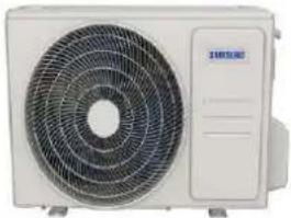 | ||
| Power supply Ph-V-Hz 220V,1Ph,50Hz 220V,1Ph,50Hz | |||
| Cooling | Capacity | Btu/h 9000 | 12000 |
| Input | W | 732 | |
| Rated current | A | 3.33 | |
| EER | W/W | 3.60 | |
| Heating | Capacity | Btu/h | / |
| Input | W | / | |
| Rated current A | / | / | |
| COP | W/W | / | |
| Rated Power Input | W | 1250 | |
| Rated Current | A | 7 | |
| Starting current | A | 18.5 | |
| Indoor fan motor | Model | YKFG-20-4-5-21 | |
| Input | W | 44.1 44.1 | |
| Capacitor | uF | 1.5 | |
| Speed(Turbo/Hi/Mi/Lo) | r/min | 1250/1200/1050/950 | |
| Indoor coil | a.Number of rows | 2.0 | |
| b.Tube pitch(a)x row pitch(b) | mm | 21x13.37 | |
| c.Fin spacing | mm | 1.3 | |
| d.Fin type (code) | Hydrophilic aluminum | ||
| e.Tube outside dia.and type | mm | Φ7,Inner groove tube | |
| f.Coil length x height x width | mm | 605x231x26.74+605x105x26.74 | |
| g.Number of circuits | 2 | ||
| Indoor air flow (Turbo/Hi/Mi/Lo) | m3/h | 560/530/450/400 | |
| Indoor noise level (Turbo/Hi/Mi/Lo) | dB(A) | 44//43/40/36.5 | |
| Indoor unit | Dimension(W*D*H) | mm | 806x200x296 |
| Packing (W*D*H) | mm | 875x285x380 | |
| Net/Gross weight | kg | 9.6/11.6 | |
| Qty'per 20'/40'/40'HQ | Indoor unit | 326/668/770 | |
2-2 Product Specifications
| Compressor | Model KSN89V11VEZ3 | KSM120V2UFT | ||
| Type ROTARY ROTARY | ||||
| Brand GMCC GMCC | ||||
| Capacity W 2720 3040/3070 | ||||
| Input | W | 668 | 1040/1075 | |
| Rated current(RLA) | A | / | 4.85/4.60 | |
| Locked rotor Amp(LRA) | A | / | 25 | |
| Thermal protector | / | / | ||
| Thermal protector position | INTERNAL | INTERNAL | ||
| Capacitor | μF | 25.0 | 35.0 | |
| Refrigerant oil/oil charge | ml | VG68 - 270 | ESTEL OIL RB74A F/300 | |
| Outdoor fan motor | Model | YKT-24-6-236L | YKT-48-6-219-1 | |
| Input | W | 69.5 | 91.8 | |
| Capacitor | uF | 2 | 2.5 | |
| Speed | r/min | 770 | 840 | |
| Outdoor coil | a.Number of rows | 1.6 | 1.6 | |
| b.Tube pitch(a)x row pitch(b) | mm | 19.5x11.6 | 19.5x11.6 | |
| c.Fin spacing | mm | 1.2 | 1.2 | |
| d.Fin type (code) | Unhydrophilic aluminium | Unhydrophilic aluminium | ||
| e.Tube outside dia.and type | mm | Φ5,Inner groove tube | Φ5,Inner groove tube | |
| f.Coil length x height x width | mm | 755x507x11.6+462x507x11.6 | 875*507*23.2 | |
| g.Number of circuits | 4 | 2 | ||
| Outdoor air flow | m3/h | 2100 | 2250 | |
| Outdoor noise level | dB(A) | 53.5 | 55.5 | |
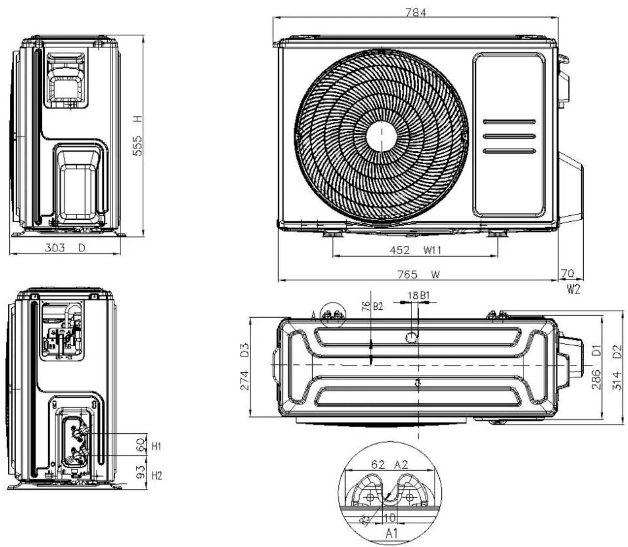
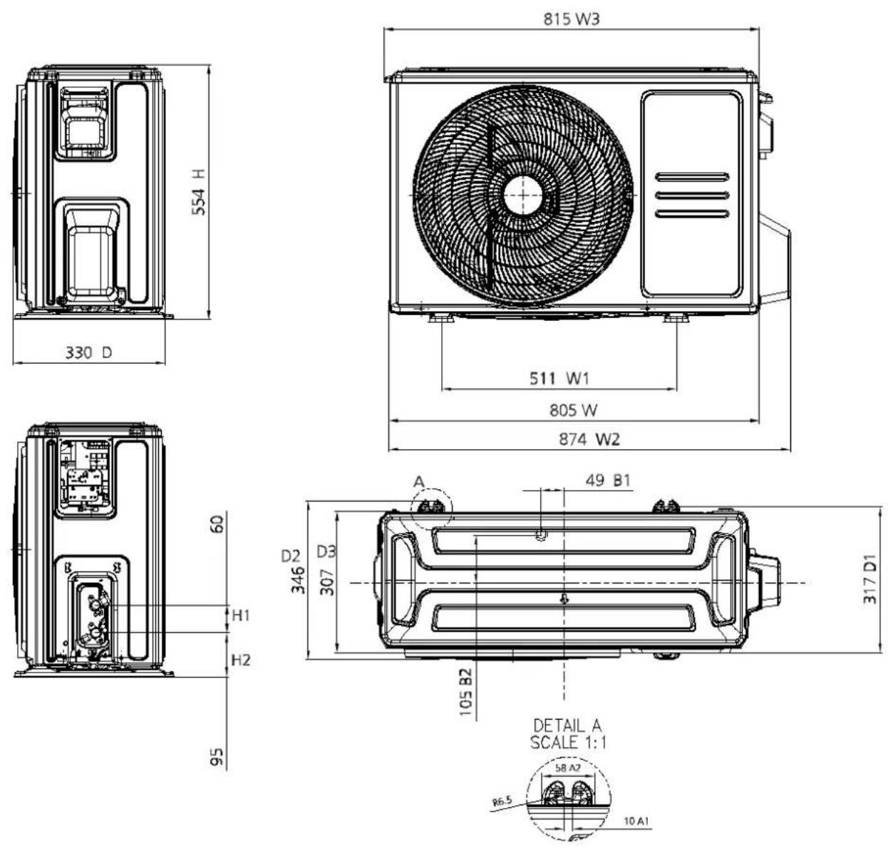
| Outdoor unit | Dimension(W*D*H) | mm | 765x303x555 805x330x554 | |
| Packing (W*D*H) | mm | 887x337x610 | 915x370x615 | |
| Net/Gross weight | kg | 26/28.3 | 31.5/34.3 | |
| Refrigerant type | kg R32/0.55 | R32/0.6 | ||
| Design pressure | MPa | 4.3/1.7 | 4.3/1.7 | |
| Refrigerant piping | Liquid side/ Gas side | mm(inch) | Φ6.35/Φ9.52(1/4"/3/8") | Φ6.35/Φ12.7(1/4"/1/2") |
| Max. refrigerant pipe length | m | 20 | 20 | |
| Max. difference in level | m | 8 | 8 | |
| Connection wiring | 1.5x3 | 1.5x3 | ||
| Plug type | 1.5x3/no-plug | 1.5x3/no-plug | ||
| Thermostat type | Remote Control | Remote Control | ||
| Operation temperature | °C | 16~30 | 16~30 | |
| Room temperature | Indoor(cooling/ heating) | °C | 16~32/- | 16~32/- |
| Outdoor(cooling/heating) | °C | 18~43/- | 18~43/- | |
| Qty'per 20'/40'/40'HQ | Outdoor unit | 132/264/352 | 114/234/312 | |
| Indoor AR18AGHQAWKNST AR24AGHQAWKNST | ||||
| Outdoor AR18AGHQAWKXST AR24AGHQAWKXST | ||||
| Design (Indoor) | 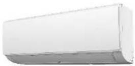 | |||
| Design (Outdoor) | 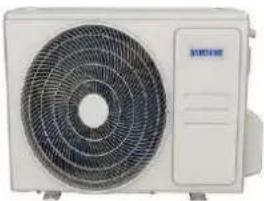 | |||
| Power supply Ph | V-Hz 220-240V,1Ph,50Hz 220V,1Ph,50Hz | |||
| Cooling | Capacity | Btu/h 18000 24000 | ||
| Input | W | 1486 | 1953 | |
| Rated current | A | 6.80 | 8.88 | |
| EER | W/W | 3.55 | 3.60 | |
| Heating | Capacity | Btu/h | / | / |
| Input | W | / | / | |
| Rated current | A | / | / | |
| COP | W/W | / | / | |
| Rated Power Input | W | 2400 | 3350 | |
| Rated Current | A | 11 | 18.0 | |
| Starting current | A | 37 | 54.5 | |
| Indoor fan motor | Model | YKFG-28-4-3-14 | YKFG-45-4-22-13 | |
| Input | W | 71.0 | 77.0 | |
| Capacitor | uF | 1.5 | 3 | |
| Speed(Turbo/Hi/Mi/Lo) | r/min | 1280/1200/1120/1000 | 1250/1200/1090/1050 | |
| Indoor coil | a.Number of rows | 2 | 2 | |
| b.Tube pitch(a)x row pitch(b) | mm | 21x13.37 | 21x13.37 | |
| c.Fin spacing | mm | 1.2 | 1.3 | |
| d.Fin type (code) | Hydrophilic aluminum | Hydrophilic aluminum | ||
| e.Tube outside dia.and type | mm | Φ7,Inner groove tube | Φ7,Inner groove tube | |
| f.Coil length x height x width | mm | 750x210x26.74+750x126x26.74 | 820x210x26.74+820x126x26.74 | |
| g.Number of circuits | 4 | 4 | ||
| Indoor air flow (Turbo/Hi/Mi/Lo) | m3/h | 720/670/620/535 | 1080/1000/910/880 | |
| Indoor noise level (Turbo/Hi/Mi/Lo) | dB(A) | 48/46/44/41 | 51.5/50.5/47.5/46 | |
| Indoor unit | Dimension( W^*D^*H ) | mm | 971x228x321 | 1082x234x337 |
| Packing ( W^*D^*H ) | mm | 1045x305x405 | 1155x415x315 | |
| Net/Gross weight | kg | 12.7/15.8 | 15.2/19.1 | |
2-2 Product Specifications
| Qty'per 20'/40'/40'HQ Indoor unit 205/415/498 195/400/464 | ||||
| Compressor | Model KSG180S1VKT KSG250V1VMT | |||
| Type ROTARY ROTARY | ||||
| Brand GMCC GMCC | ||||
| Capacity | W 5510±3% | 7760/7795 | ||
| Input | W | 1265±3% | 1815/1900 | |
| Rated current(RLA) | A | 5.6±3% | 8.35/8.30 | |
| Locked rotor Amp(LRA) | A | 37 ±10% | 54.5 | |
| Thermal protector | UP3-64/HPA-732 | / | ||
| Thermal protector position | INTERNAL | INTERNAL | ||
| Capacitor | μF | 40.0 | 60.0 | |
| Refrigerant oil/oil charge | ml | VG74/610 | VG74/740 | |
| Outdoor fan motor | Model | YKT-48-6-219-1 | YKT-60-6-40-6 | |
| Input | W | 91.8 | 133.0 | |
| Capacitor | uF | 3 | 5 | |
| Speed | r/min | 850 | 870 | |
| Outdoor coil | a.Number of rows | 2.0 | 2.0 | |
| b.Tube pitch(a)x row pitch(b) | mm | 19.5x11.6 | 21x13.37 | |
| c.Fin spacing | mm | 1.2 | 1.4 | |
| d.Fin type (code) | Unhydrophilic aluminium | Unhydrophilic aluminium | ||
| e.Tube outside dia.and type | mm | Φ5,Inner groove tube | Φ7,Inner groove tube | |
| f.Coil length x height x width | mm | 875x507x23.2 | 1005x756x26.74 | |
| g.Number of circuits | 4 | 6 | ||
| Outdoor air flow | m3/h | 2500 | 3540 | |
| Outdoor noise level | dB(A) | 58.5 | 62.0 | |
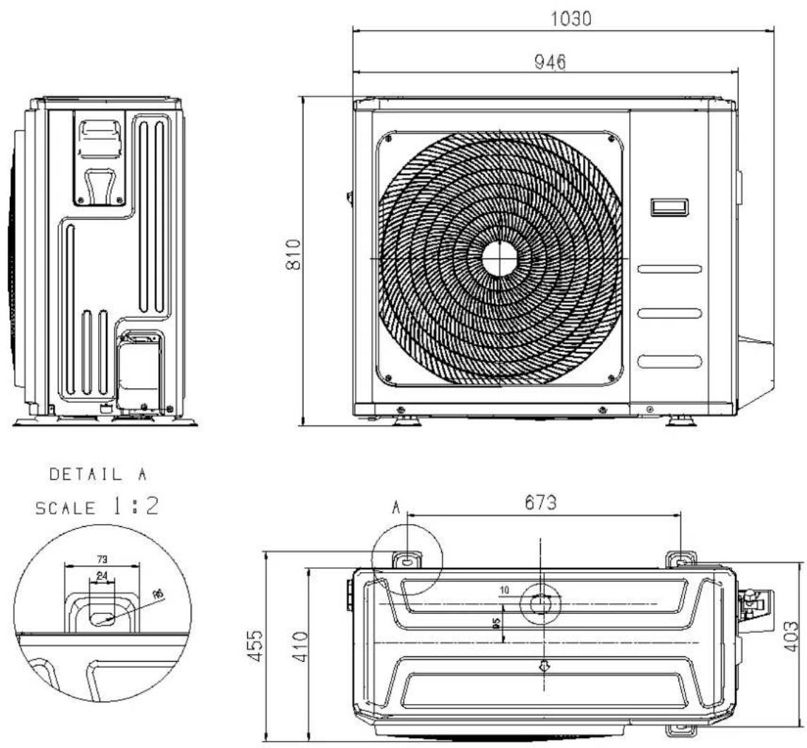
| Outdoor unit | Dimension(W*D*H) | mm | 805x330x554 | 946x410x810 |
| Packing (W*D*H) | mm | 915x370x615 | 1090x500x885 | |
| Net/Gross weight | kg 39.9/42.5 60.2/64.9 | |||
| Refrigerant type | kg R32/0.71 | R32/1.5 | ||
| Design pressure | MPa | 4.3/1.7 | 4.3/1.7 | |
| Refrigerant piping | Liquid side/ Gas side | mm(inch) | Φ6.35/Φ12.7(1/4"/1/2") | Φ9.52/Φ15.9(3/8"/5/8") |
| Max. refrigerant pipe length | m | 25 | 25 | |
| Max. difference in level | m | 10 | 10 | |
| Connection wiring | 2.5x3 | 2.5x4 | ||
| Plug type | 2.5x3/no-plug | 2.5x3/no-plug | ||
| Thermostat type | Remote Control | Remote Control | ||
| Operation temperature | °C | 16~30 | 16~30 | |
| Room temperature | Indoor(cooling/ heating) | °C | 16~-32/- | 16~-32/- |
| Outdoor(cooling/heating) | °C | 18~-43/- | 18~-43/- | |
| Qty'per 20'/40'/40'HQ | Outdoor unit | 114/234/312 | 44/96/138 | |
2-3 Accessories
The air conditioning system comes with the following accessories. Use all of the installation parts and accessories to install the air conditioner. Improper installation may result in water leakage, electrical shock and fire, or cause the equipment to fail. The items are not included with the air conditioner must be purchased separately.
| Name of Accessories | Q'ty(pc) | Shape | Name of Accessories | Q'ty(pc) | Shape |
| Manual | 2~3 |  | Remote controller | 1 |  |
| Drain joint(for cooling & heating models) | 1 |  | Battery | 2 |  |
| Seal(for cooling & heating models) | 1 |  | Remote controller holder(optional) | 1 |  |
| Mounting plate | 1 |  | Fixingscrew for remote controller holder(optional) | 2 |  |
| Anchor | 5~8 (depending on models) | 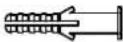 | Small Filter(Need to be nstaled on the back of main air filter by the authorized technic an while nstaaling the machine) | 1~2 (depending on models) |  |
| Mounting plate fixing screw | 5~8 (depending on models) |  |
| Name | Shape Quantity(PC) | ||
| Connecting pipe assembly | Liquid side | Φ6.35(1/4in) | Parts you must purchase separately. Consult the dealer about the proper pipes size of the unit you purchased. |
| Φ9.52(3/8in) | |||
| Gas side | Φ9.52(3/8in) | ||
| Φ12.7(1/2in) | |||
| Φ16(5/8in) | |||
| Φ19(3/4in) | |||
| Magnetic ring and belt (if supplied, please refer to the wiring diagram to install it on the connective cable.) |  |  Pass the belt through the hole of the Magnetic ring to fix it on the cable Pass the belt through the hole of the Magnetic ring to fix it on the cable | Var es by model |
3. Alignment and Adjustments
3-1 Checking before use
Operation ranges
The table below indicates the temperature and humidity ranges the air conditioner can be operated within. Refer to the table for efficient use.
| Mode | Indoor temperature | Outdoor temperature | Indoor humidity |
| Cooling | 16°C~32°C | 18°C~43°C | Relative humidity 80% or less |
| Heating | - | - | - |
| Dry | 10°C~32°C | 18°C~43°C | - |
▶ If the air conditioner operates in cooling mode for long period of time in high humidity area, dew may be formed.
Maintaining your air conditioner
Internal protections via the unit control system
This internal protection operates if an internal fault occurs in the air conditioner.
| Type | Description |
| Protect compressor | The air conditioner does not start operating immediately to help protect the compressor of the outdoor unit after it has been started. |
When the indoor unit encounters a recognized error, the operation lamp will flash in a corresponding series, the 1 mer lamp may turn on or begin flashing, and an error code will be displayed. These error codes are described in the following tables:
| Operation Lamp | Timer Lamp | Display Error Information | ||
| ... | df | Deirost | Normal Display, not error code | |
| ... Cu | Filter cleaning reminder | ng | deripower on display for 15 seconds | |
| ... Cu | Sel' clean | |||
| ... F | Fter replacement | em | nderipower on display for 15 seconds | |
| ... FP | Heating in | room temperature | under 8°C | |
| ... RP | AP mode of WiFi connection | |||
| ... CP | Remote switched off | |||
| 1 time OFF | EXOO Indoor unit EE PROM parameter erro | |||
| 2 times | OFF | EU01 | Indoor / outdoor unit communication error (for some models) | |
| 3 times | OFF | EX02 | Zero-crossing signal detection error | |
| 4 times | OFF | EX03 | The indoor fan speed is operating outside of the normal range | |
| 6 times | OFF EX80 | Indoor room temperature sensor T1 is n open circuit or has short circuited | ||
| 6 times | OFF | EX61 | Evaporator coil temperature sensor T2 is n open circuit or has short circuited | |
| 9 times | OFF | EX0b | Communication error between display board and main board | |
| 8 times | OFF EU0C Refrigerant leak detected | |||
| 5 times | OFF EC92 | Condenser coil temperature sensor T3 or Outdoor room temperature sensor T4 is in open circuit or has short circuited (for some models) | ||
| 12 times | OFF EC07 | The outdoor fan speed is operating outside of the normal range (for some models) | ||
| 7 times | FLASH PO03 | High pressure protection (for some models) | ||
For other errors:
The display board may show a garbled code or a code undefined by the service manual. Ensure that this code is not a temperature reading.
Troubleshooting:
Test the unit: using the remote control. If the unit does not respond to the remote, the indoor PCB requires replacement. If the unit responds, the display board requires replacement.
3-3 Checking the remote controller
- Point the remote controller towards the remote controller receiver of the indoor unit.
- When you properly press the button on the remote controller, you will hear beep sound from the indoor unit and a transmit indicator(💡) appears on the remote controller display.
Remote controller buttons
RG10B(S2)/BGEF
Remote Screen Indicators
Information are displayed when the remote controller is power up.
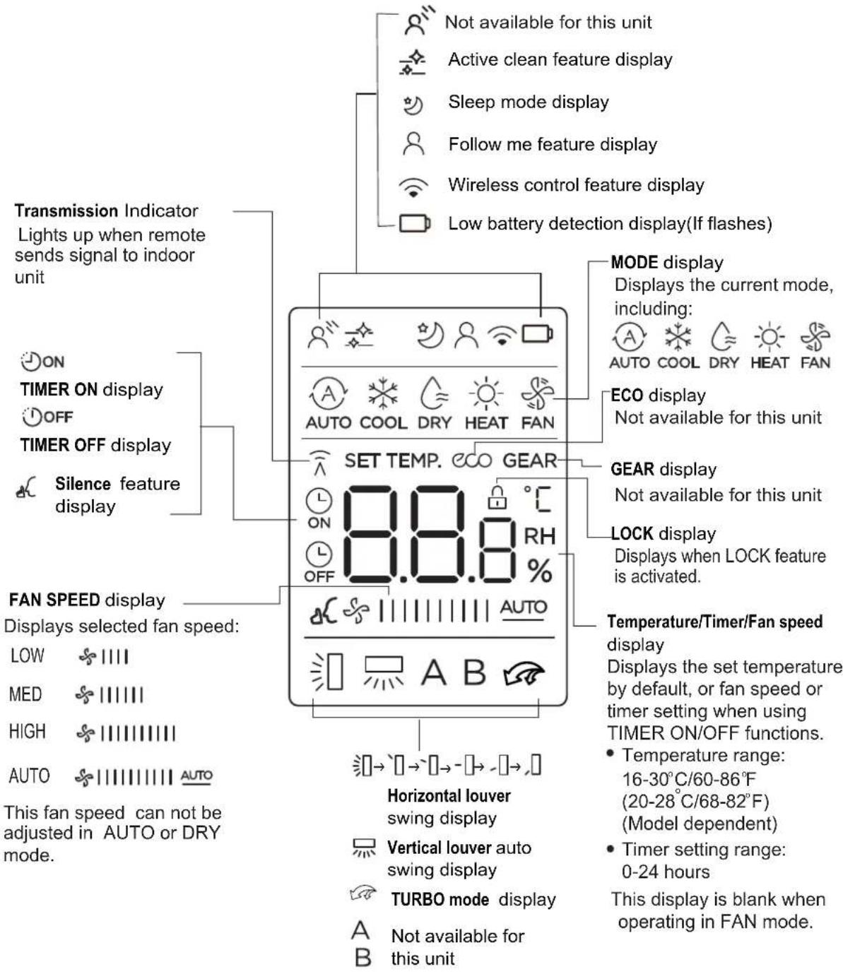
Note:
All indicators shown in the figure are for the purpose of clear presentation. But during the actual operation, only the relative function signs are shown on the display window.
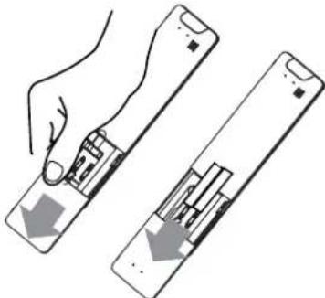
Inserting and Replacing Batteries
Your air conditioning unit may come with two batteries(some units). Put the batteries in the remote control before use.
-
Slide the back cover from the remote control downward, exposing the battery compartment.
-
Insert the batteries, paying attention to match up the (+) and (-) ends of the batteries with the symbols inside the battery compartment.
-
Slide the battery cover back into place.
natural_image
Illustration of a hand holding a device with two views of the screen (no text or symbols)! BATTERY NOTES
For optimum product performance:
- Do not mix old and new batteries, or batteries of different types.
- Do not leave batteries in the remote control if you don't plan on using the device for more than 2 months.
BATTERY DISPOSAL
Do not dispose of batteries as unsorted municipal waste. Refer to local laws for proper disposal of batteries.
4. Disassembly and Reassembly
■ Necessary Tools
| Item | Remark |
| +SCREW DRIVER |  |
| MONKEY SPANNER | 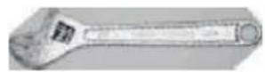 |
| -SCREW DRIVER | 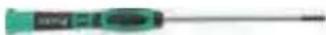 |
Dimension
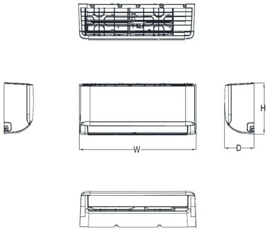
| Capacity | W(mm) | D(mm) | H(mm) |
| 9K~12K | 806 | 200 | 295 |
| 18K | 971 | 228 | 321 |
| 24K | 1082 | 234 | 337 |
4-1 Indoor Unit
1. Front Panel
| Procedure Illustration | |
| 1) Hold the front pane by the tabs on the both sides and if: it (see CJ_AG_001). | 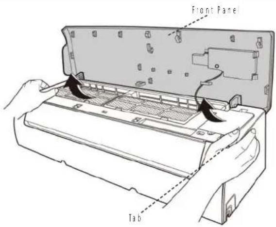 CJ_AG_001 CJ_AG_001 |
| 2) Push up the bottom of an air filter (step 1), and then pull out downwards (step 2) (see CJ_AG_002). | 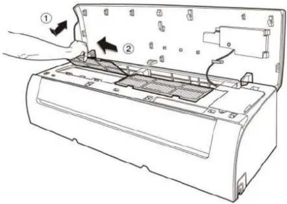 CJ_AG_002 CJ_AG_002 |
Note: This section is for reference only. Actual unit appearance may vary.
| Procedure Illustration | |
| 3| Open the horizontal louver and push the hook towards left to open it (see CJ_AG_003). | 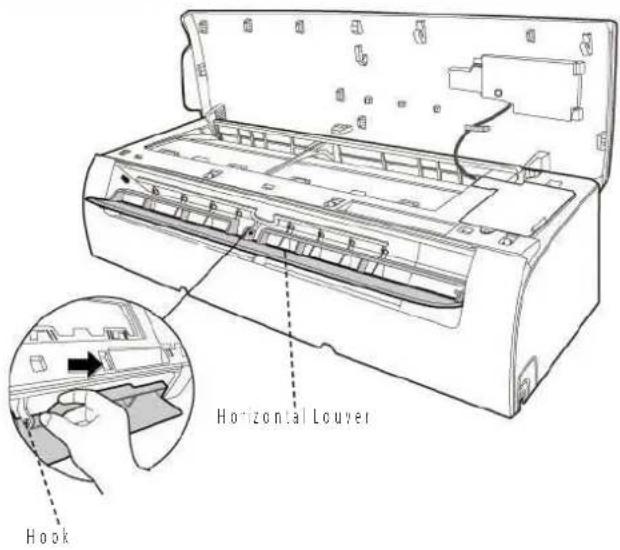 CJ_AG_003 CJ_AG_003 |
| 4| Bend the horizontal louver lightly by both hands to loosen the hooks, then remove the horizontal louver (see CJ_AG_003). | 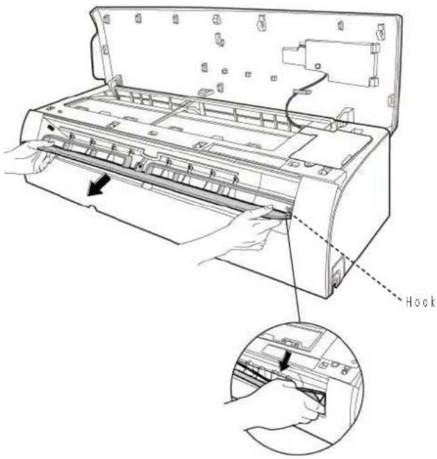 CJ_AG_004 CJ_AG_004 |
Note: This section is for reference only. Actual unit appearance may vary.
Procedure Illustration
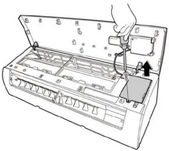
5: Pry the electrical cover by a screw driver, and rotate it towards left, then remove it. (see Cl_AG_005)
natural_image
Line drawing of a hand inserting into an air conditioner unit with a valve (no text or symbols)CJ_AG_005
6: Disconnect the connector for display board. [see CI_AG_006].
7| Sid the front panel side to side to release each axis (see Cl_AG_006)
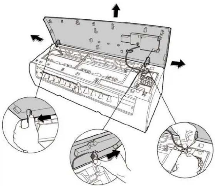
CJ_AG_006
Note: This section is for reference only. Actual unit appearance may vary.
| Procedure Illustration | |
| 8) Open the screw cap and then remove the 3 screws (see CJ_AG_008). | 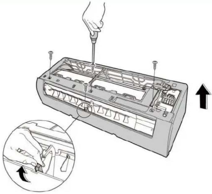 CJ_AG_007 CJ_AG_007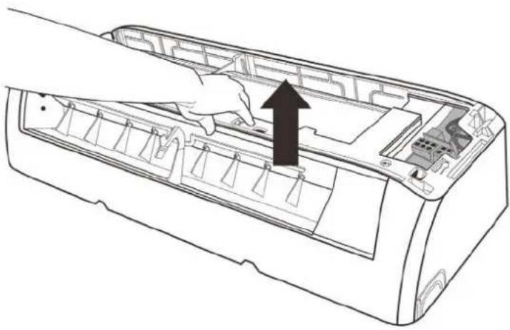 CJ_AG_008 CJ_AG_008 |
| 9) Release the hooks with hands (see CJ_AG_008) |
Note: This section is for reference only. Actual unit appearance may vary.
| Procedure Illustration | |
| 10|Release the 5 hooks in the back (see CJ_AG_009). | 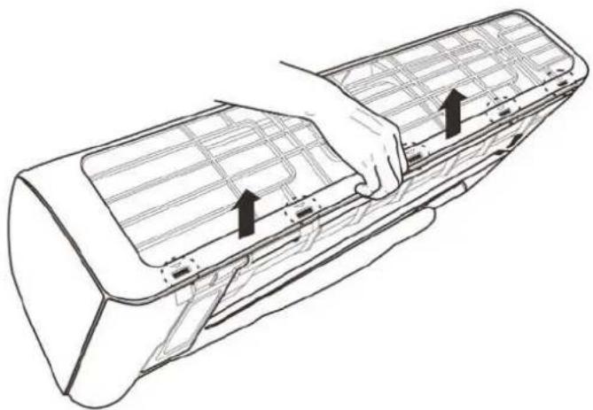 CI_AG_009 CI_AG_009 |
| 11|Pull out the pane frame whie pushing the hook through a clearance between the panel frame and the heat exchanger (see CJ_AG_010) | 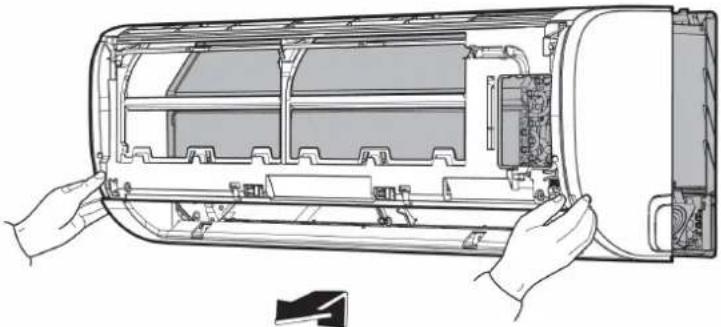 CI_AG_010 CI_AG_010 |
Note: This section is for reference only. Actual unit appearance may vary.
Procedure Illustration
12 | Release the 5 hooks of the vertical blades, then pull the vertical blades rightward and remove it (see Cl_AG_011).
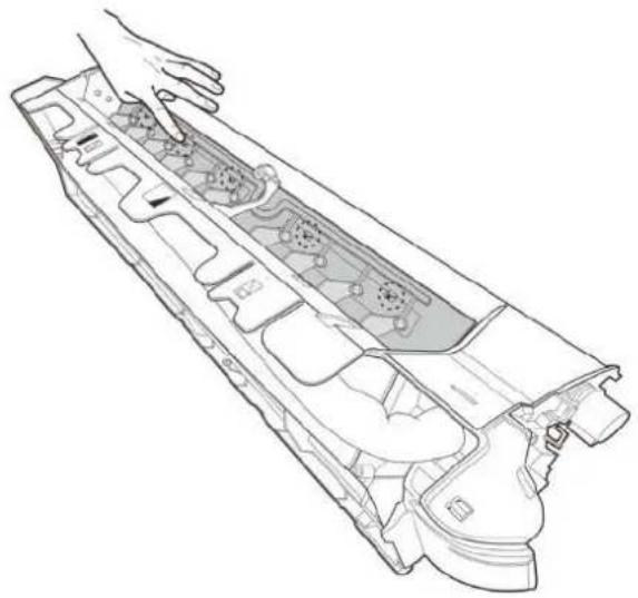
natural_image
Technical line drawing of a mechanical component with internal gears and housing (no text or symbols)CJ_AG_011
13|Remove 1 screw o: the display board. (see C._AG_012).
14|Rotate the display board in the direction shown in the right picture |see Cl_AG_012|
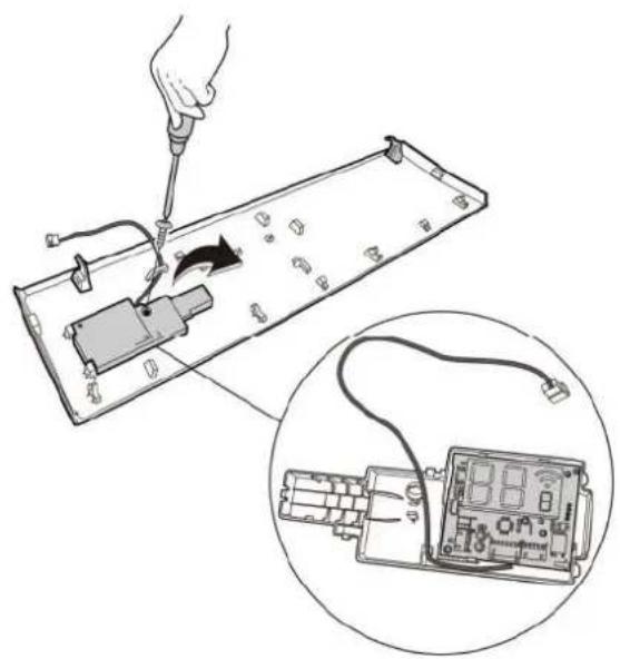
natural_image
Illustration of a hand using a screwdriver to switch an electronic component into a circuit board, with an inset showing the same device (no text or symbols present)CJ_AG_012
Note: This section is for reference only. Actual unit appearance may vary.
2. Electrical parts (Antistatic gloves must be worn.)
Note: Remove the front panel (refer to 1. Front panel) before disassembling electrical parts.
| Procedure Illustration | |
| 1) Remove one fixing screw of electrical control box subassembly (see CJ_AG_013).If you want to repair the electrical control box components, perform the first step; you want to repair the main control board assembly, perform steps 2 to 5 below. | 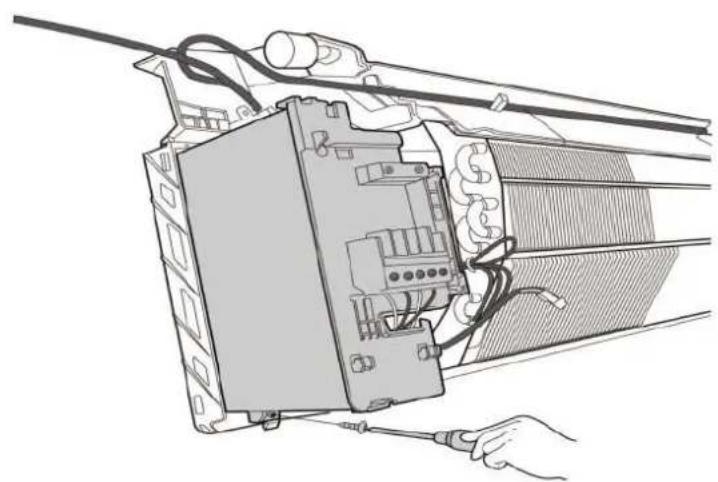 CJ_AG_013 CJ_AG_013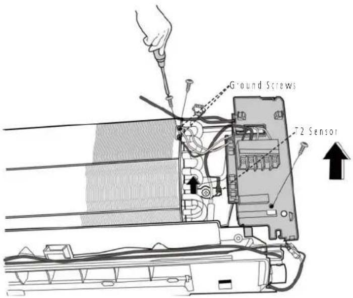 CJ_AG_014 CJ_AG_014 |
| 2) Cut the ribbon by a shear, then pull out the coil temperature sensor (T2) (see C._AG_014). | |
| 3) Remove one fixing screw of the electronic control box and two screws used for the ground connection (see CJ_AG_014). | |
| 4) Pull out the electrical main board along the direction indicated right image, (see CI_AG_015) | 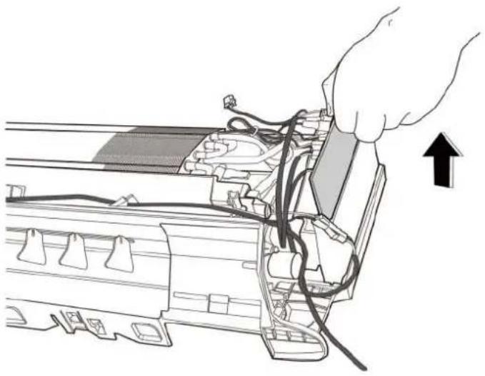 CI_AG_015 CI_AG_015 |
| 5) Disconnect the connectors and remove main contro board, (see CI_AG_016), | 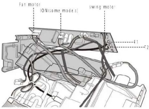 CJ_AG_016 CJ_AG_016 |
Note: This section is for reference only. Actual unit appearance may vary.
3. Evaporator
Note: Remove the front panel and electrical parts (refer to 1. Front panel and 2. Electrical parts) before disassembling evaporator.
| Procedure Illustration | |
| 1; Disassemble the p pe h der located at the rear of the unit (see CJ_AG_017). | 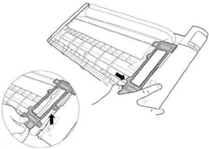 CI_AG_017 CI_AG_017 |
| 2; Remove the 1 screw on the evaporator located at the fixed plate (see CJ_AG_018). | 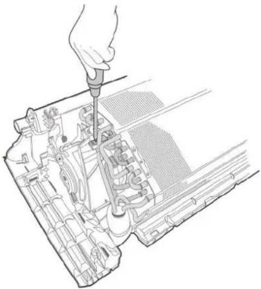 CI_AG_018 CI_AG_018 |
Note: This section is for reference only. Actual unit appearance may vary.
| Procedure Illustration | |
| 3) Remove 1 screw and release the hook on the evaporator (see CI_AG_019) | 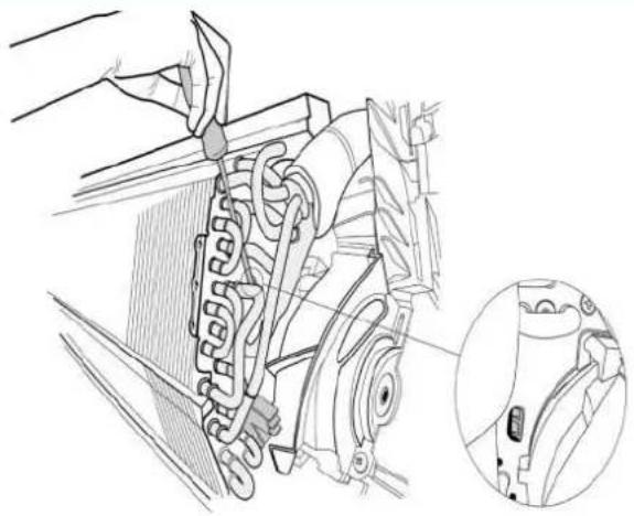 CI_AG_019 CI_AG_019 |
| 4) Remote the 2 screws on the evaporator located at the fixed plate (see CI_AG_020). | 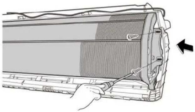 CI_AG_020 CI_AG_020 |
| 5) Pull out the evaporator (see CI_AG_021). | 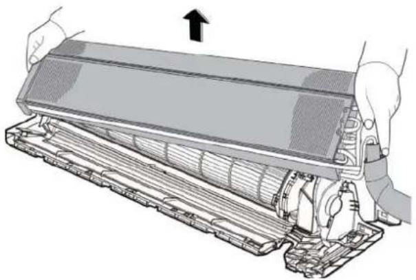 CI_AG_021 CI_AG_021 |
Note: This section is for reference only. Actual unit appearance may vary.
4 Fan motor and fan
- Evaporator), before disassembling fan motor and fan.
| Procedure Illustration | |
| 1; Remove the two screws and remove the fixing board of the fan motor (see Cl_AG_022). | 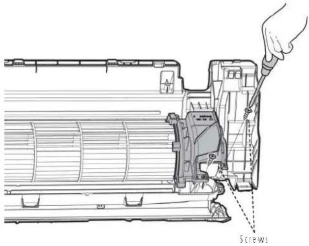 Cl_AG_022 Cl_AG_022 |
| 2; Remove the bearing sleeve (see Cl_AG_023). | 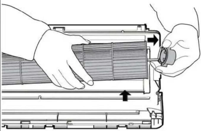 Cl_AG_023 Cl_AG_023 |
Note: This section is for reference only. Actual unit appearance may vary.
| Procedure Illustration | |
| 3: Remove the fixing screw (see C:\_AG_024).4: Pull out the fan motor and fan assembly from the side | 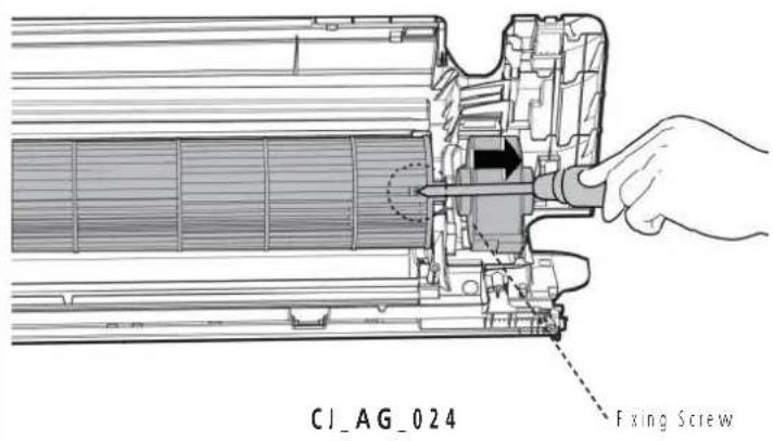 |
Note: This section is for reference only. Actual unit appearance may vary.
5 Step motor
Note: Remove the front panel and electrical parts (refer to 1. Front panel, 2. Electrical parts) before disassembling step motor.
| Procedure Illustration | |
| 1) Remove the two screws, then remove the horizontal swing motor|see Cl_AG_025|. | 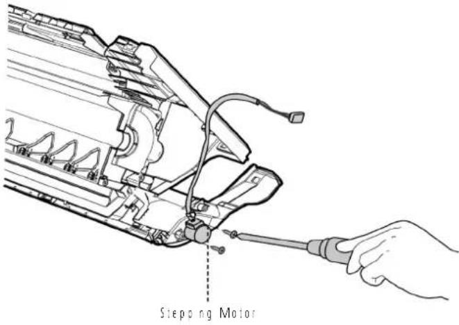 CI_AG_025 CI_AG_025 |
| 2) Remove 1 screw, then remove the vertical swing motor|see Cl_AG_026| [for some units] | 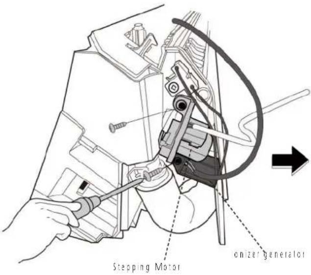 CI_AG_026 CI_AG_026 |
Note: This section is for reference only. Actual unit appearance may vary.
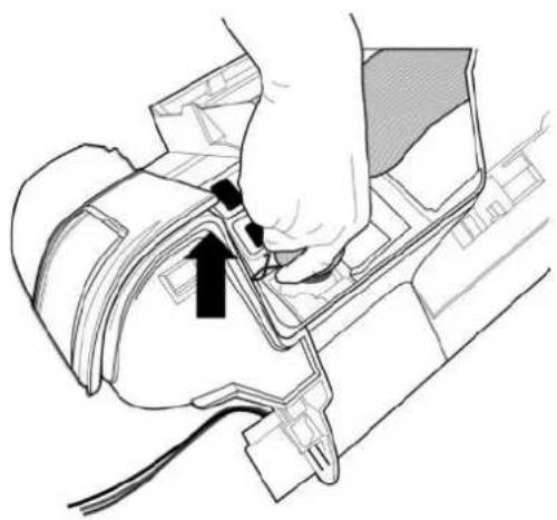
6 Drain Hose
Procedure Illustration
1) Rotate the fixed wire clockwise and caied in right image (see CJ_AG_027).
2) Pull up the drain hose to remove it (see C!_AG_028).

natural_image
Illustration of hands using a tool to adjust or install a mechanical component, no text or symbols presentC1_AG_027
natural_image
Diagram of a hand inserting a component into a vehicle's head panel, showing wiring and a black arrow indicating direction (no text or symbols present)CJ_AG_028
Note: This section is for reference only. Actual unit appearance may vary.
Model 9k
Model 12k/18k
Model 24k
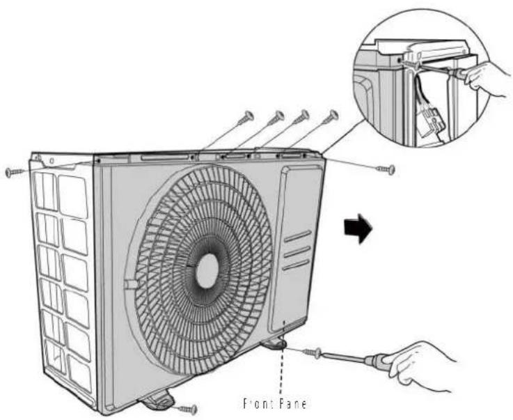
1 Panel Plate
| Procedure Illustration | |
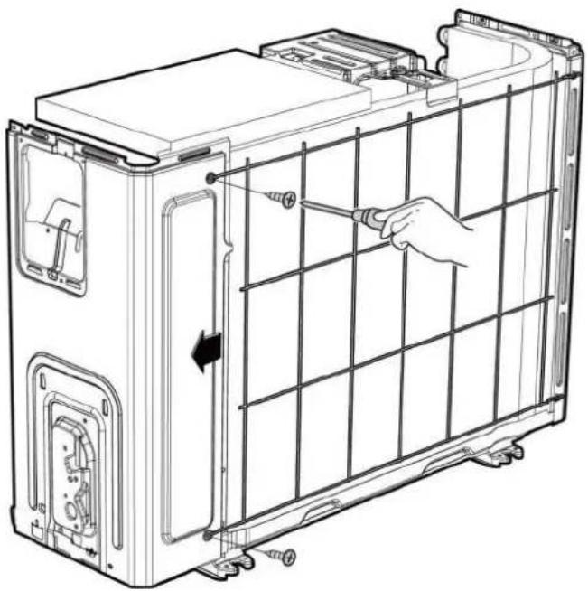
| 1) Turn off the air conditioner and the power breaker.2) Remove the screw of the big handle and then remove the big handle (1 screws) (see CJ_X230_001). | 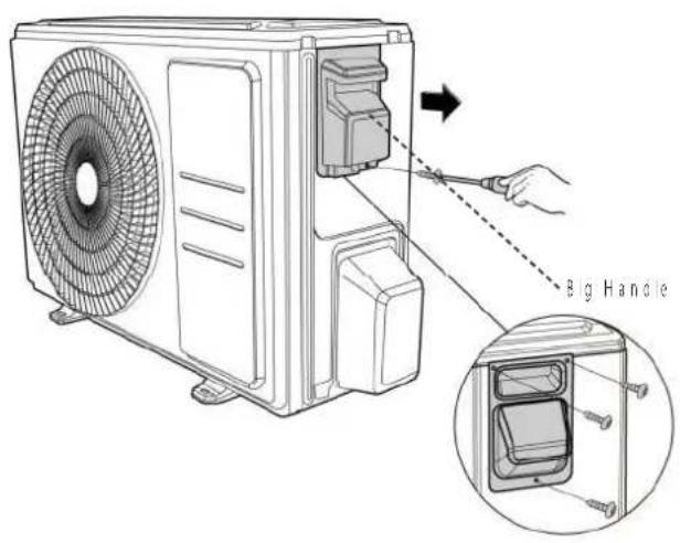 CJ_X230_001 CJ_X230_001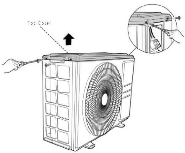 CJ_X230_002 CJ_X230_002 |
| 3) Remove the screws of the top cover and then remove the top cover (4 screws) One of the screws is acated underneath the big handle (see CJ_X230_002). |
Note: This section is for reference only. Actual unit appearance may vary.
Procedure Illustration
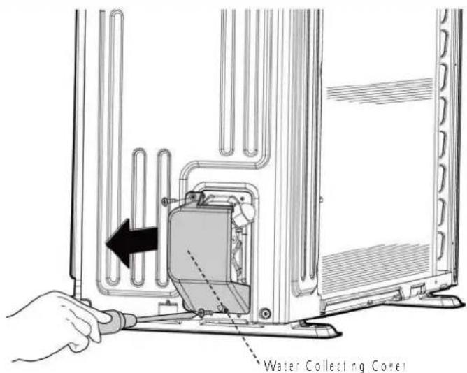
4: Remove the screws of water collecting cover and then remove the water collecting cover 12 screws; see Cl_X230_0031.
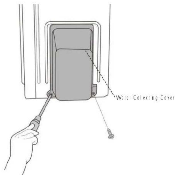
CJ_X230_003
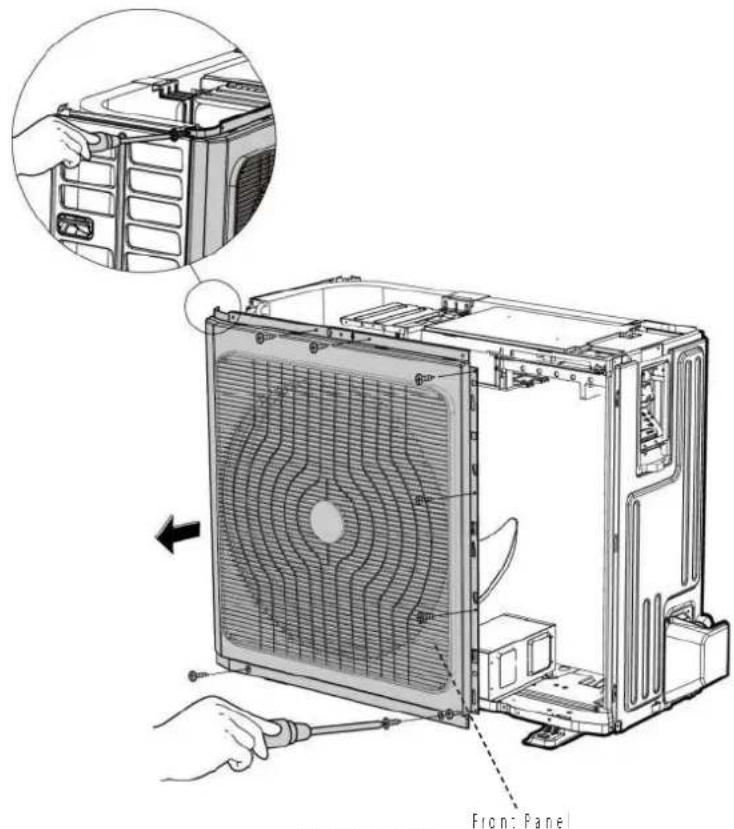
5: Remove the screws of the front panel and then remove the front panel |7 screws|onof modes or 9 screws|nverter modes|see Cl_ X230_0041.
CJ_X230_004
Note: This section is for reference only. Actual unit appearance may vary.
Procedure Illustration
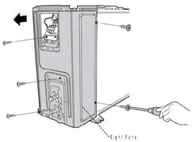
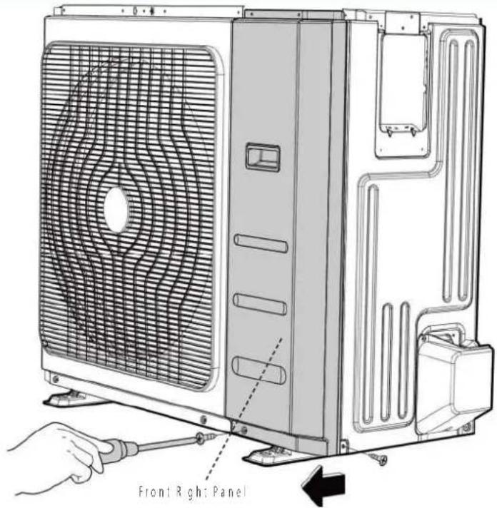
6) Remove the screws of the right panel and then remove the right panel 15 screws (see C1_X230_005).
CJ_X230_005
Note: This section is for reference only. Actual unit appearance may vary.
1.2 D30 (Model 24k)
| Procedure Illustration | |
| 1) Turn off the air conditioner and the power breaker.2) Remove the screws of the big hand e and then remove the big handle 12 screwsl [see CJ_D30_001].3) Remove the screws of the top cover and then remove the top cover 14 screwsl Two of the screws is ocaied underneath the big handle (see CJ_D30_002). | 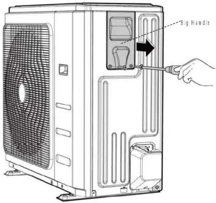 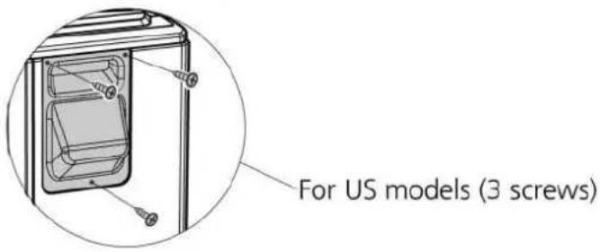 CJ_D30_001 CJ_D30_001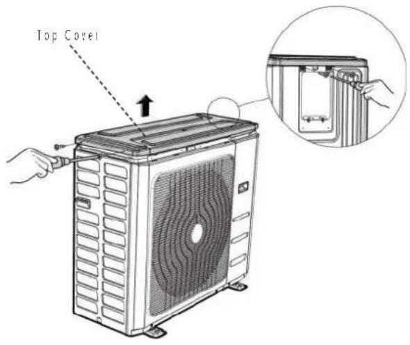 CJ_D30_002 CJ_D30_002 |
Note: This section is for reference only. Actual unit appearance may vary.
Procedure Illustration
4: Remove the screws of the front-right panel and then remove the front-right panel |2 screws| (see C1_D30_003).
CJ_D30_003
5: Remove the screws of the front pane and then remove the front panel 19 screws | see C._D30_004
CJ_D30_004
Note: This section is for reference only. Actual unit appearance may vary.
Procedure Illustration
6: Remove the screws of water collecting cover and then remove the water collecting cover (2 screw) (see CJ_D30_0051
7) Remove the screws of the rear net and then remove the rear net (2 screws, see C._D30_006). [for some models]
CJ_D30_005
natural_image
Technical line drawing of a battery pack assembly with hand holding screwdriver (no text or symbols)CJ_D30_006
Note: This section is for reference only. Actual unit appearance may vary.
| Procedure Illustration | |
| 8) Remove the screws of the right panel and then remove the right panel |8 screws| see CJ_D30_007. | 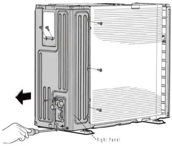 CJ_D30_007 CJ_D30_007 |
Note: This section is for reference only. Actual unit appearance may vary.
2 Electrical parts
WARNING: Antistatic gloves must be worn when you disassemble the electronic box. Note: Remove the air outlet grille(refer to 1 Panel Plate) before disassembling electrical parts.
Model 9k/12k/18k
| Procedure Illustration | |
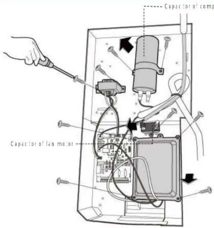
| 1) Remove the two screws fixed the electronic control board (see CI_ODU_PCB_001).2) Disconnect the connectors for fan motor. [Blue wire, yellow wire, red wire, brown wire and black wire. The blue wire and red wire are on the capacitor. The black wire connects with terminal 4.] (see CI_ODU_PCB_001)3) Disconnect the wires connected to the compressor. [Black wire connects with terminal 1. blue wire and red wire connect with the compressor capacitor] (see CI_ODU_PCB_001)4) Disconnect the wires connected to 4-way valve [Blue wires on terminal 2 & 3] (see CI_ODU_PCB_001)5) Remove the fixing screw of the compressor capacitor, then pull it out (see CI_ODU_PCB_001)6) Remove the electrical parts (see CI_ODU_PCB_001)7) For models with AC conductor, remove 2 screws of it showed in the figure. | 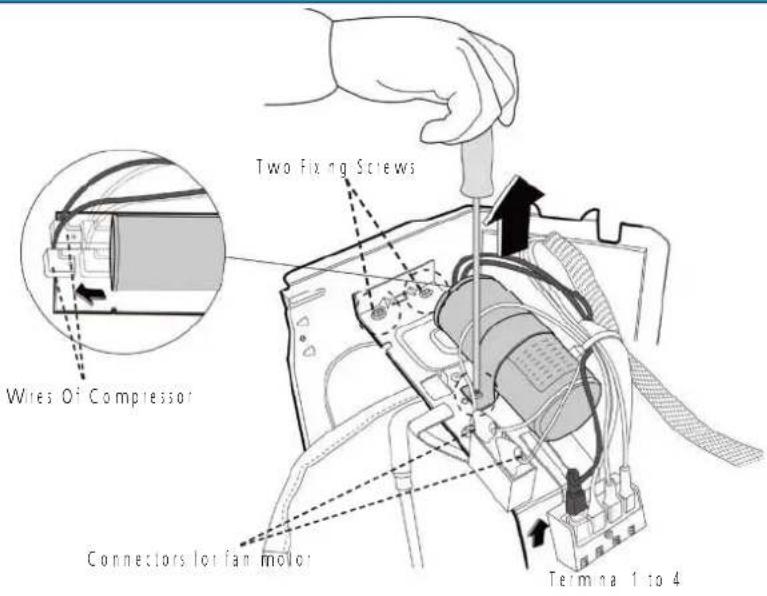 CI_ODU_PCB_001-01 CI_ODU_PCB_001-01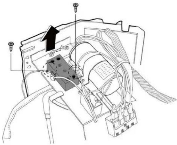 CI_ODU_PCB_001-02 CI_ODU_PCB_001-02 |
Note: This section is for reference only. Actual unit appearance may vary.
| Procedure Illustration | |
| 8) For models with subzero refrigeration control board, remove 3 screws of it showed in the figure. | 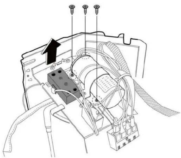 CI_ODU_PCB_001-03 CI_ODU_PCB_001-03 |
| 9) The subzero refrigeration control board is in the back of the meda sheet. | 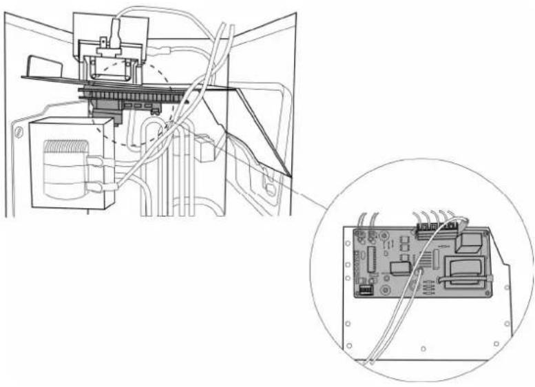 CI_ODU_PCB_001-04 CI_ODU_PCB_001-04 |
Note: This section is for reference only. Actual unit appearance may vary.
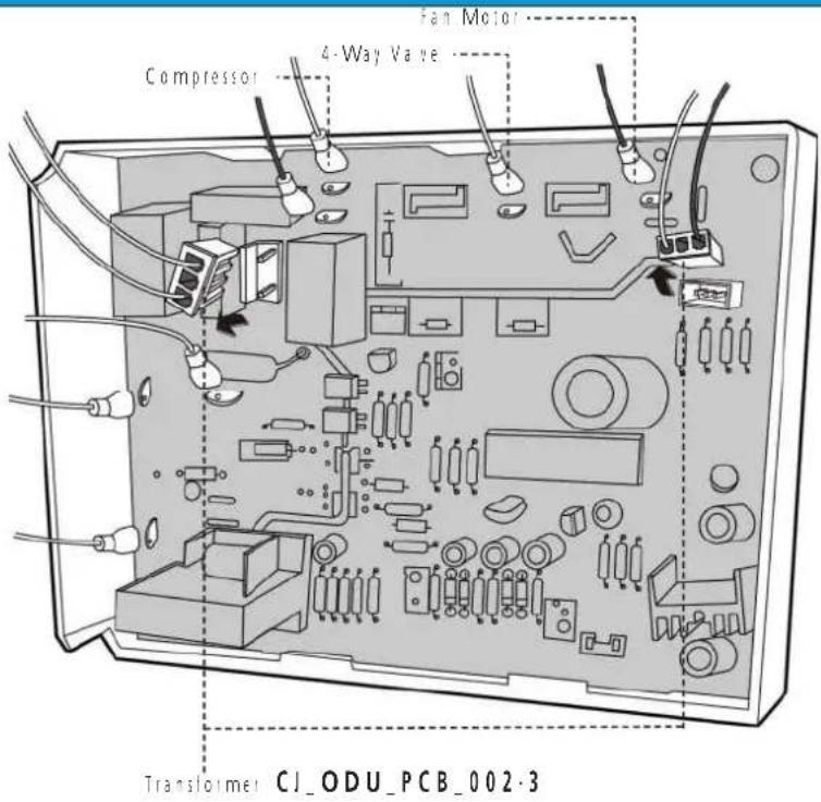
Model 24k
Procedure Illustration
1) Remove the fixing screws of the compressor capacitor, then pull out (see CJ_ODU_PCB_002-1)
2| Remove 2 screws of the transformer and then remove it (see CJ_ODU_PCB_002-1)
31 Remove the fixing screws of the fan motor capacitor, then remove it (see CJ_ODU_PCB_002-1)
4) Remove the 4 screws of the electron c installing box and then remove it. (see CI_ODU_PCB_002-1) (for some models)
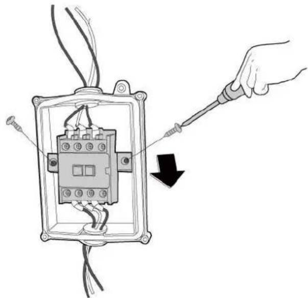
51 Remove the 2 screws of the AC contactor and then remove it. [see CJ_ODU_PCB_002-2]
CJ_ODU_PCB_002-1
natural_image
Diagram of a hand using a screwdriver to adjust an electrical contactor component (no text or symbols present)CJ_ODU_PCB_002·2
Note: This section is for reference only. Actual unit appearance may vary.
Procedure Illustration
6 | Disconnect the wires connected to the compressor. [Red wire connects with PCB board, others connects with terminals] (see CJ_ODU_PCB_002-3) [For some models]
7 | Disconnect the connectors for fan motor. Blue wire, red wire, brown wire and back wire. The blue wire and brown wire are on the capacitor. The black wire connects with a terminal. And the red wire is on the borad.; see C1_ODU_PCB_002-3 (For some models)
8 | Disconnect the wires connected to 4-way valve (see CI_ODU_PCB_002-3) | For some models
9| Disconnect the wires connected to the transformer. (see CJ_ODU PCB_002-3; For some models)
10 | Disconnect the other wires connected to terms as (see CJ_ODU_PCB_002-3) For some models
11|Remove the PCB board. I see C!_
ODU_PCB_002-3|For some models
Note: This section is for reference only. Actual unit appearance may vary.
3 Fan Assembly
Note: Remove the panel plate (refer to 3.1 Panel Plate) before disassembling fan.
| Procedure Illustration | |
| 1) Remove the nut securing the fan with a spanner; see CI_ODU_FAN_001;2) Remove the fan. | 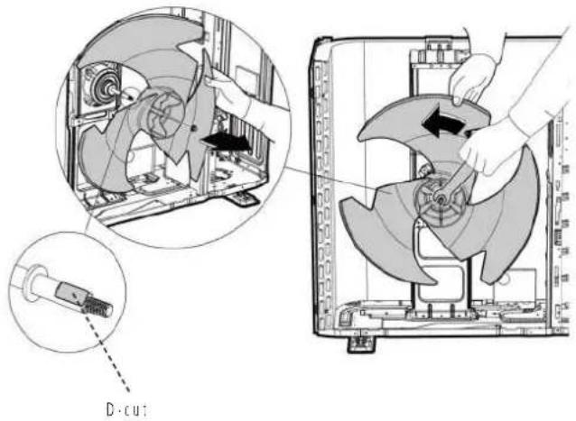 CI_ODU_FAN_001 CI_ODU_FAN_001 |
Note: This section is for reference only. Actual unit appearance may vary.
4 Fan Motor
Note: Remove the panel plate and the connection of fan motor on PCB (refer to 3.1 Panel Plate and 3.2 Electrical parts) before disassembling fan motor.
| Procedure Illustration | |
| 3| Remove the fixing screws of the fan motor14 screws| see CI_ODU_MOTOR_0011.4| Remove the fan motor. | 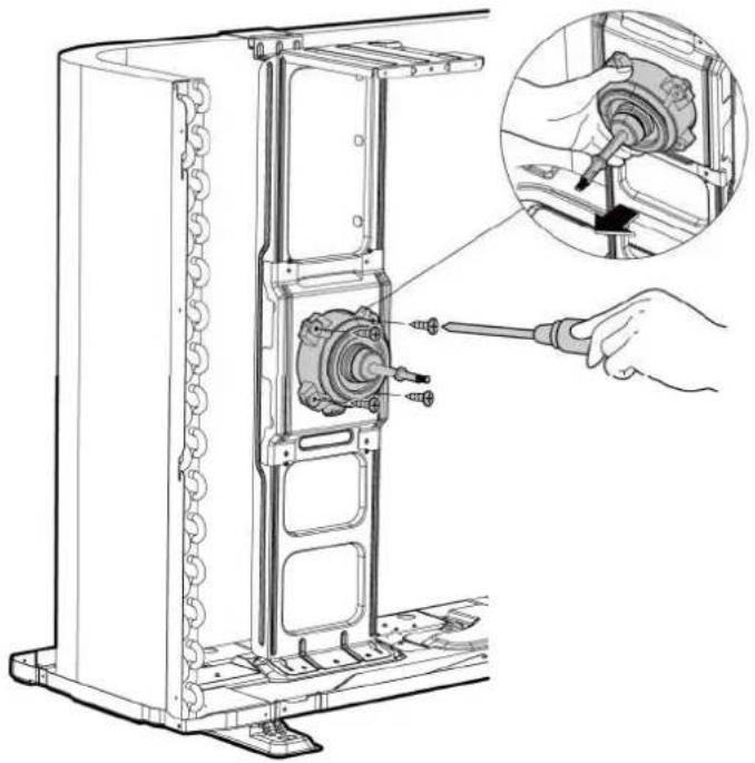 CI_ODU_MOTOR_001 CI_ODU_MOTOR_001 |
Note: This section is for reference only. Actual unit appearance may vary.
5 Sound blanket
Note: Remove the panel plate (refer to 3.1 Panel plate) before disassembling sound blanket.
| Procedure Illustration | |
| 1| Remove the sound banker:side and top| Isee CJ_ODU_BLANKET_001| | 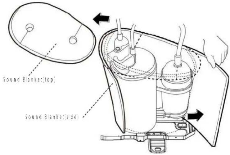 CJ_ODU_BLANKET_001 CJ_ODU_BLANKET_001 |
Note: This section is for reference only. Actual unit appearance may vary.
6 Compressor
WARNING: Evacuate the system and confirm that there is no refrigerant leit in the system before removing the four-way valve and the compressor. For R32 & R290, you should evacuate the system with the vacuum pump, flush the system with nitrogen; then repeat the two steps before heating up the brazed parts. The operations above should be implemented by professionals.
Note: Remove the panel plate, connection of compressor on PCB (refer to 3.1 Panel plate and 3.2 Electrical parts) before disassembling sound blanket.
| Procedure Illustration | |
| 1| Remove the flange nut of terminal cover and remove the terminal cover | see CJ_ODU_COMP_001| | 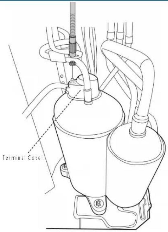 CI_ODU_COMP_001 CI_ODU_COMP_001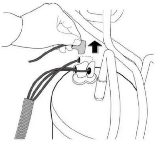 CI_ODU_COMP_002 CI_ODU_COMP_002 |
| 2| Disconnect the connectors (see CJ_ODU_COMP_002). |
Note: This section is for reference only. Actual unit appearance may vary.
| Procedure Illustration | |
| 3) Remove the hex nuts and washers securing the compressor, located on the bottom plate (see CJ_ODU_COMP_003). | 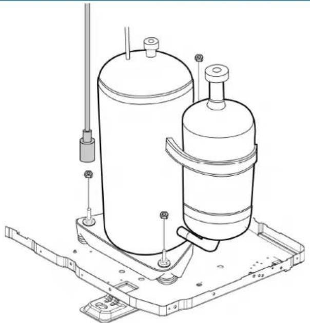 CI_ODU_COMP_003 CI_ODU_COMP_003 |
| 4) Heat up the brazed parts and then remove the discharge pipe and the suction pipe (see CJ_ODU_COMP_004).5) Lift the compressor from the base pan assembly with plie's | 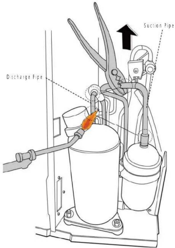 CI_ODU_COMP_004 CI_ODU_COMP_004 |
Note: This section is for reference only. Actual unit appearance may vary.
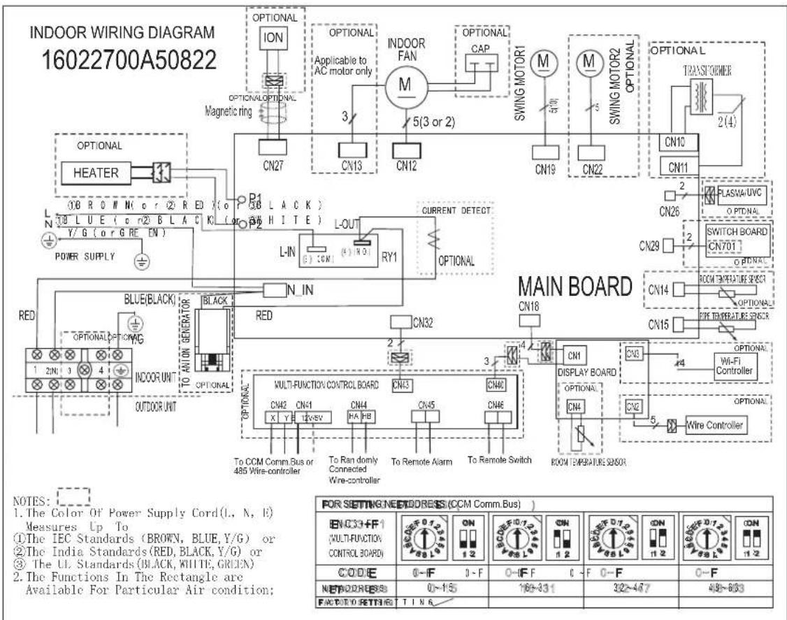
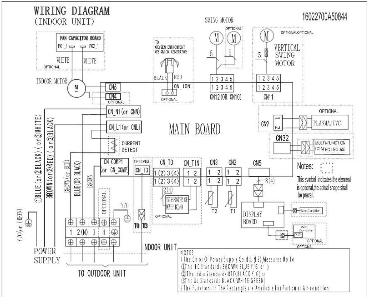
5. Wiring Diagram
Indoor unit abbreviations
| Abbreviation Paraphrase | |
| Y/G Yellow-Green Conductor | |
| ION Positive and Negative Ion Generator | |
| CAP Capacitor | |
| PLASMA Electronic Dust Collector | |
| L LIVE | |
| N NEUTRAL | |
| Heater The Electric Heating Belt of Indoor Unit | |
| T1 Indoor Room Temperature | |
| T2 Coil Temperature of Indoor Heat Exchanger |
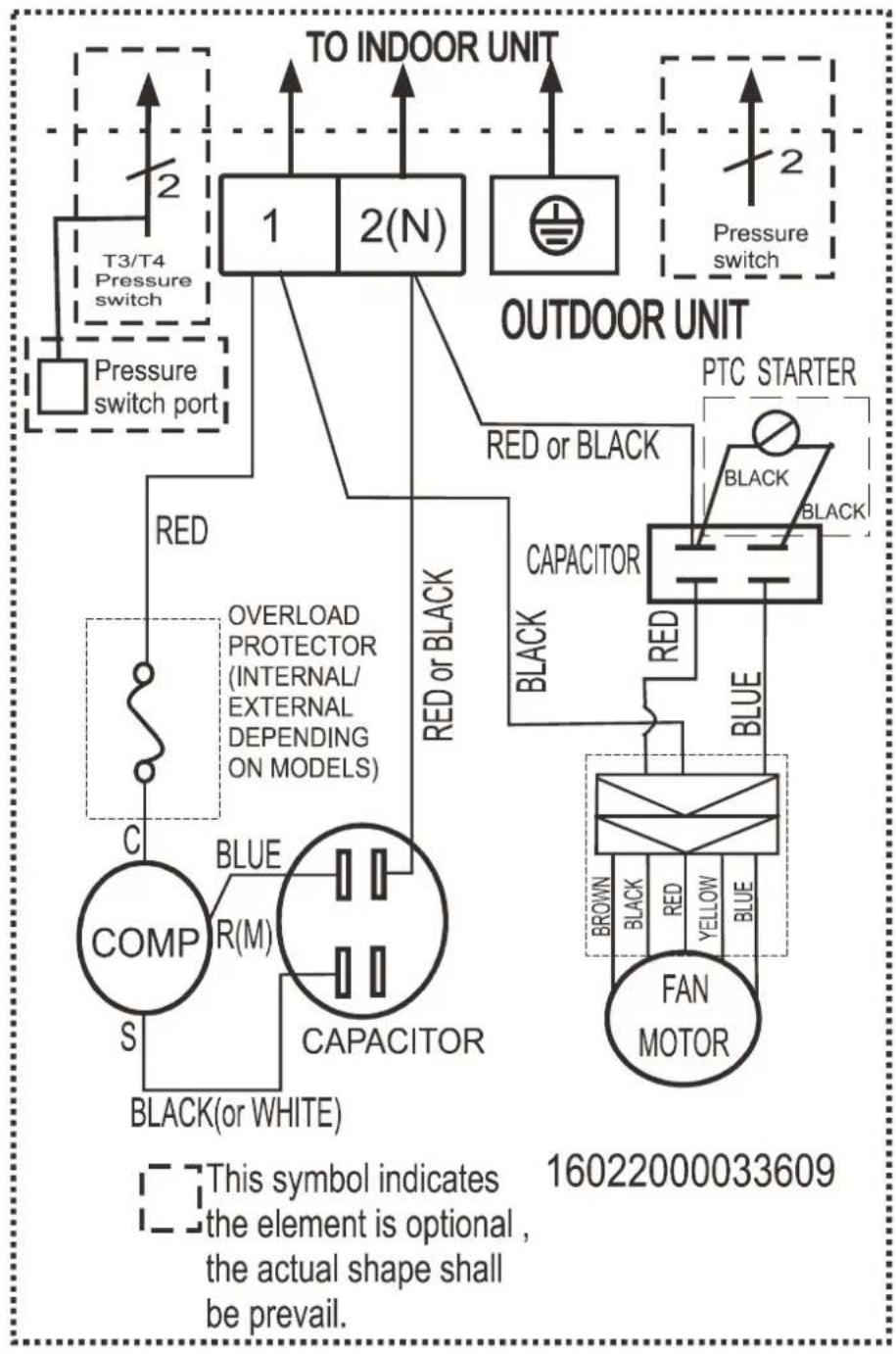
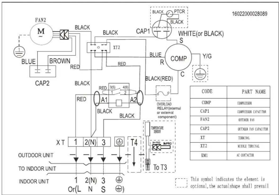
Outdoor unit abbreviations
| Abbreviation Paraphrase | |
| COMP Compressor | |
| CAP1 Compressor Capacitor | |
| FAN2 Outdoor Fan | |
| CAP2 Outdoor Fan Capacitor | |
| T3,RT3 Coil Temperature of Condenser | |
| L-PRO | Low Pressure Switch |
| H-PRO | High Pressure Switch |
| TRANS1 | Transformer |
| KM1 | AC Contactor |
| CT | Current Inductor |
5-1 Indoor Unit
Model 9k/12k/18k
Model 24k
flowchart
graph TD
    subgraph MAIN BOARD
        M["Motor"] --> CN12["CN12 (OR CN10)"]
        M --> CN11["CN11"]
        M --> M["M"]
        M --> M["M"]
        M --> M["M"]
        M --> M["M"]
        M --> M["M"]
        M --> M["M"]
        M --> M["M"]
        M --> M["M"]
        M --> M["M"]
        M --> M["M"]
        M --> M["M"]
        M --> M["M"]
        M --> M["M"]
        M --> M["M"]
        M --> M["M"]
        M --> M["M"]
        M --> M["M"]
        M["Main Board"] --> CN12
        CN12 --> CN11
        CN11 --> CN9
        CN9 --> PLASMAUVC["PLASMA/UVC"]
        CN32 --> MULTIFUNCTION["CONTROLBOARD"]
        MULTIFUNCTION --> MULTIFUNCTION
    end

    subgraph INDoor UNIT
        CN6 --> TO_OXYEN_ENRICHMENT_OR_ANION_GENERATOR
        CN4 --> TO_OXYEN_ENRICHMENT_OR_ANION_GENERATOR
        CN1 --> TO_OXYEN_ENRICHMENT_OR_ANION_GENERATOR
        CN1 --> TO_OXYEN_ENRICHMENT_OR_ANION_GENERATOR
        CN_N1["CN_N1 (or CNN)"]
        CN_L1["CN_L1 (or CNL)"]
        CN_T3["CN_T3"]
        CN_T0["CN_T0 (2) 3(4)"]
        CN_TIN["CN_TIN (2) 3(4)"]
        ONTHSPOWER["ONTHSPOWER OR POWER BOARD"]
        ONTHSPOWER --> ONTHSPOWER
        ONTHSPOWER --> ONTHSPOWER
        ONTHSPOWER --> ONTHSPOWER
        ONTHSPOWER --> ONTHSPOWER
        ONTHSPOWER --> ONTHSPOWER
        ONTHSPOWER --> ONTHSPOWER
        ONTHSPOWER --> ONTHSPOWER
        ONTHSPOWER --> ONTHSPOWER
        ONTHSPOWER --> ONTHSPOWER
        ONTHSPOWER --> ONTHSPOWER
    end

    subgraph INDoor Environment
        CN6 --> TO_OXYEN_ENRICHMENT_OR_ANION_GENERATOR
        CN4 --> TO_OXYEN_ENRICHMENT_OR_ANION_GENERATOR
        CN1 --> TO_OXYEN_ENRICHMENT_OR_ANION_GENERATOR
        CN1 --> TO_OXYEN_ENRICHMENT_OR_ANION_GENERATOR
        CN_T3 --> TO_OXYEN_ENRICHMENT_OR_ANION_GENERATOR
        ONTHSPOWER --> ONTHSPOWER
    end

    style MAIN BOARD fill:#f9f,stroke:#333
    style INDoor UNIT fill:#ccf,stroke:#333

    note right of MAIN BOARD: This symbol indicates the element is optional, the actual shape shall be prevail.
    note right of INDoor Environment: The Co or Of Power Supp Cord, Line Me Measures Up To.
    note left of INDoor Environment: The EC Standards BROWN BLUE Y/G or )
    note right of INDoor Environment: The India Standards RED BLACK Y/G or
    note right of INDoor Environment: The UL Standards BLACK WHITE GREEN
    note right of INDoor Environment: The Functions In The Rectangle are Available For Particular Air-condition.

    %% Note to the diagram; this figure is a schematic representation of the circuit design.
Model 9k/12k/18k
flowchart
graph TD
    A["TO INDOOR UNIT"] --> B["1"]
    A --> C["2(N)"]
    D["Pressure switch"] --> E["T3/T4 Pressure switch"]
    F["Pressure switch port"] --> G["Overload Protector (INTERNAL/ EXTERNAL DEPENDING ON MODELS)"]
    G --> H["COMP S"]
    H --> I["R(M)"]
    I --> J["CAPACITOR"]
    J --> K["BLACK(or WHITE)"]
    L["OUTDOOR UNIT"] --> M["PTC STARTER"]
    M --> N["BLACK"]
    M --> O["BLACK"]
    M --> P["CAPACITOR"]
    Q["FAN MOTOR"] --> R["BROWN"]
    Q --> S["BLICK"]
    Q --> T["RED"]
    Q --> U["YELLOW"]
    Q --> V["BLE"]
    W["RED or BLACK"] --> X["Black"]
    X --> Y["BLICE"]
    Y --> Z["Blue"]
    AA["RED or BLACK"] --> AB["Black"]
    AB --> AC["BLICE"]
    AD["BLUE or BLACK"] --> AE["Black"]
    AE --> AF["BLICE"]
6-1. Indoor Main PCB
9k/12k/18k
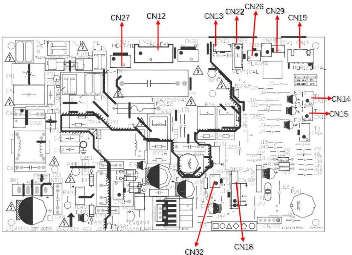
CN12-FAN\_IN
1: FAN CAP
2: FAN CONTROL-L
3: FAN CONTROL-N
CN27-ION
1: ION CONTROL-L
2: ION CONTROL-N
CN18-DISPLAY
1: GND
2: +5V
3#4: DISPLAY SIGNAL
CN13-FAN BACK
1: +12V
2: FEEDBACK SIGNAL
3: GND
CN29-SWITCH BOARD
1: SWITCH SIGNAL
2: GND
CN22-SWING MOTOR2
1\~#4: STEP MOTOR SIGNAL
5: +12V
N14- TEMPERATURE SENSOR
1: ROOM SENSOR
2: +5V
CN19-SWING MOTOR1
1\~#4: STEP MOTOR SIGNAL
5: +12V
CN15-TEMPERATURE SENSOR
1: PIPE SENSOR
2: +5V
CN32- MULTI-FUNCTION BOARD 12V POWER
1: +12V
2: GND
CN26-PLASMA
1: PLASMA CONTROL
2: +12V
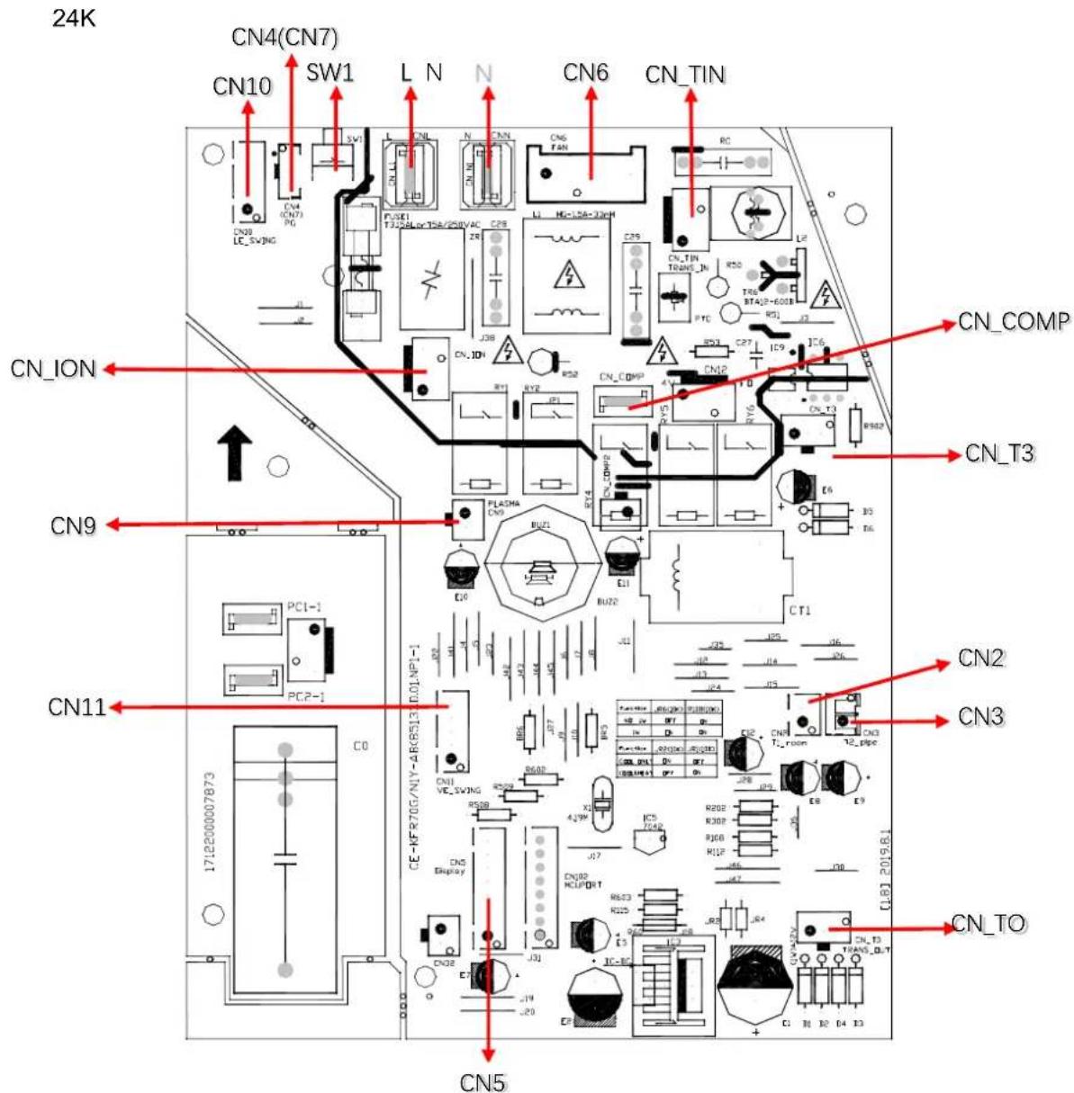
CN6-FAN IN
1:DC_N
2: FAN SIGNAL +220V
3: NOT USE
CN-ION-ION
CN ION: +220V
CN N3: ION CONTROL-N
CN7(CN4)- FAN BACK
1: +12V
2: FEEDBACK SIGNAL
3: GND
SW1-SWITCH BOARD
1: SWITCH SIGNAL
2,#3: GND
CN11-SWING MOTOR2
1\~#4: STEP MOTOR SIGNAL
5: +12V
CN3-TEMPERATURE SENSOR
1: PIPE SENSOR
2: +5V
CN10-SWING MOTOR1
1\~#4: STEP MOTOR SIGNAL
5: +12V
CN\_T3-T3 TEMPERATURE
1: +5V
2 NOT USE
3:GND
CN5-DISPLAY
1: GND
2: +5V
3: REC SIGNAL
4: 164 SDA SIGNAL
5: COM2
6: COM3
7: COM1
8: 164 SCL SIGNAL
CN2- TEMPERATURE SENSOR
1: ROOM SENSOR
2: +5V
N-N\_IN
1:N INPUT #1:+12#1:L INPUT
L-L\_IN
CN9-PLASMA
2: PLASMA CONTROL
CN\_TO-TRANSFORMER OUTPUT
1: +-12V
2: NOT USE
3: +-12V
CN\_TIN- TRANSFORMER INPUT
1: +-220V
2: NOT USE
3: +-220V
CN\_COMP-COMPRESSOR CONTROL OUTPUT
1:220V
6-2 Display PCB
9k/12k/18k/24k
![IFR-35G/HP2IN8Y-AG400JB5NNXX5XP1 [V.7] 2018J2J8 1712200034617B CN4 CN3 CN1 CN2](/content/2026/06/1167497/images/e56e1fef44982d4654b630000efc12a8d143cb08423e69c2522fb46ebb10fb41.jpg)
CN1-Display
1: Display signal
2: +5V
3#4: GND
5: +5V
6#7: MULTI-Function board signal
1-#3: MULTI-Function board
4-#7: Display
CN2-Wire Controller
1: +5V
2: GND
3-#4: Infrared emission
5: Not use
CN3-WIFI Controller
1: GND
2: RXD
3: TXD
4: +5V
CN4-Room Temperature Sensor(Reserved)
1: +5V
2: Room Sensor
7. Operating Instructions
7-1 Name of Each Part
NOTE: Different models have different front panels and display windows. Not all the display codes describing below are available for the air conditioner you purchased. Please check the indoor display window of the unit you purchased.
Illustrations in this manual are for explanatory purposes. The actual shape of your indoor unit may be slightly different. The actual shape shall prevail.
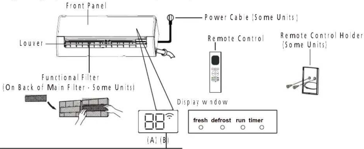
"fresh " when Fresh and UV-C lamp(if any)feature is activated(some units)
"defrost" when defrost feature is activated.
" run " when the unit is on.
"timer " when TIMER is set.
" ∩ " when Wireless Control feature is activated(some units)
"88" Displays temperature, operation feature and error codes:
" ON " for 3 seconds when:
- TIMER ON is set (if the unit is OFF, "ON" remains on when TIMER ON is set)
- FRESH, UV-C lamp, SWING, TURBO, ECO, or SILENCE feature is turned on
"OF" for 3 seconds when
- TIMER OFF is set
- FRESH, UV-C lamp, SWING, TURBO, ECO, or SILENCE feature is turned off
" dF " when defrosting
"FP" when 8°C heating feature is turned on(some units)
“ [E] when Active Clean feature is turned on (For Inverter split type) when unit is self-cleaning(For Fixed-speed type)
Display Code Meanings
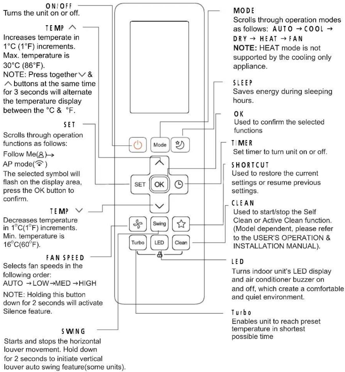
Before you begin using your new air conditioner, make sure to familiarize yourself with its remote control. The following is a brief introduction to the remote control itself.
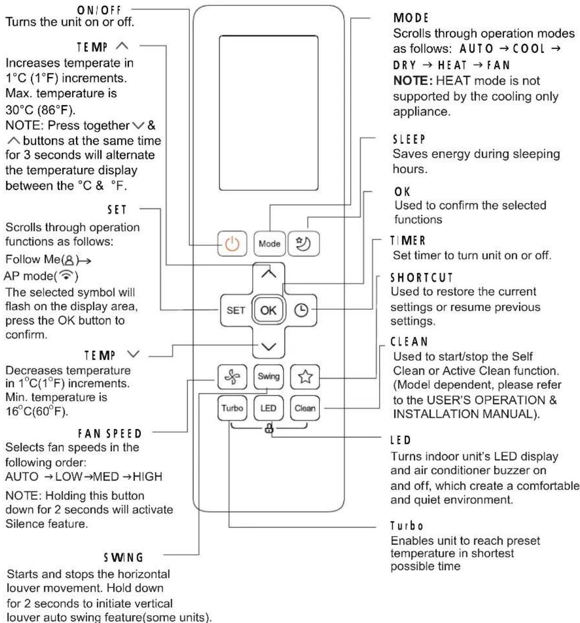
flowchart
graph TD
    A["ON/OFF"] --> B["Turns the unit on or off."]
    C["TEMP"] --> D["Increases temperate in 1°C (1°F) increments. Max. temperature is 30°C (86°F). NOTE: Press together & buttons at the same time for 3 seconds will alternate the temperature display between the °C & °F."]
    E["SET"] --> F["Scrolls through operation functions as follows: Follow Me(8)→AP mode( compass). The selected symbol will flash on the display area, press the OK button to confirm."]
    G["SET"] --> H["OK"]
    I["MODE"] --> J["Mode"]
    K["SET"] --> L["Switch"]
    M["SET"] --> N["LED"]
    O["SET"] --> P["Clean"]
    Q["MODE"] --> R["Scrolls through operation modes as follows: AUTO → COOL → DRY → HEAT → FAN NOTE: HEAT mode is not supported by the cooling only appliance."]
    S["SLEEP"] --> T["Saves energy during sleeping hours."]
    U["OK"] --> V["Used to confirm the selected functions"]
    W["TIMER"] --> X["Set timer to turn unit on or off."]
    Y["SHORTCUT"] --> Z["Used to restore the current settings or resume previous settings."]
    AA["CLEAN"] --> AB["Used to start/stop the Self Clean or Active Clean function. (Model dependent, please refer to the USER'S OPERATION & INSTALLATION MANUAL)."]
    AC["LED"] --> AD["Turns indoor unit's LED display and air conditioner buzzer on and off, which create a comfortable and quiet environment."]
    AE["TURBO"] --> AF["Enables unit to reach preset temperature in shortest possible time"]
RG10B(S2)/BGEF
8. Troubleshooting
1. Safety Caution

WARNING
Be sure to turn off all power supplies or disconnect all wires to avoid electric shock. While checking indoor/outdoor PCB, please equip oneself with antistatic gloves or wrist strap to avoid damage to the board.

WARNING
Electricity remains in capacitors even when the power supply is off. Ensure the capacitors are fully discharged before troubleshooting.
Test the voltage between the two pins of the compressor capacitor, if the voltage is zero, the capacitors are fully discharged.
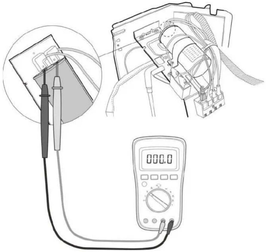
natural_image
Illustration of a multimeter setup with a close-up of a device connected to a digital multimeter (no text or symbols visible)Note: This picture is for reference only. Actual appearance may vary.
2. General Troubleshooting
2.1 Error Display (Indoor Unit)
When the indoor unit encounters a 'recognized error', the operation amp will flash in a corresponding series, the timer lamp may turn on or begin flashing, and an error code will be displayed. These error codes are described in the following tables
| Operation Lamp | Timer Lamp | Display Error Information | ||
| ... | dF | Defrost | Normal Display, not error code | |
| ... | cu | Filter cleaning reminder, power on display for 15 seconds | ||
| ... - Cu | Self clean | |||
| ... - F | Filter replacement, rem | nder|power on display for 15 seconds; | ||
| ... - FP | Heating in room temperature under 8°C | |||
| ... - RP | AP mode of WIFI connection | |||
| ... - CP | Remote switched oil | |||
| 1 : me | OFF | EX00 | Indoor unit EEPROM parameter error | |
| 2 : mes | OFF | EL01 | Indoor | outdoor unit communication error for some models | |
| 3 : mes | OFF | EX02 | Zero-crossing s gna detection error | |
| 4 : mes | OFF | EX03 | The indoor fan speed s operating outside of the normal range | |
| 6 : mes | OFF EX80 | Indoor room temperature sensor T1 s in open circuit or has short circuited | ||
| 6 : mes | OFF | EH61 | Evaporator coil temperature sensor T2 is in open circuit or has short circuited | |
| 9 : mes | OFF | EX0b | Communication error between display board and main board | |
| 8 : mes | OFF | EL0C | Refrigerant leak detected | |
| 5 : mes | OFF EC92 | Condenser coil temperature sensor T3 or Outdoor room temperature sensor T4 is n open circuit or has short circuited for some models | ||
| 12 : mes | OFF EC07 | The outdoor fan speed is operating outside of the normal range for some models | ||
| 7 : mes | FLASH | PC03 | High pressure protection for some models | |
For other errors:
The display board may show a garbled code or a code undefined by the service manual. Ensure that this code is not a temperature reading.
Troubleshooting:
Test: the unit using the remote control. If the unit does not respond to the remote, the indoor PCB requires replacement. If the unit responds, the display board requires replacement.
3. Information Inquiry
• To enter information inquiry status, complete the following procedure within 10 seconds:
- Press LED 3 times.
-
Press SWNG 3 times
-
Finish 1 and 2 within 10 seconds, you will hear beeps for two seconds, which means the unit goes into parameter checking mode.
- Use the LEDio DO NOT DISTURB and SWING or AR DIRECTION buttons to cycle through information displayed.
- Pressing LED or DO NOT DISTURBI displays the next code in the sequence. Pressing SWING or AIR D RECTIONI will show the previous.
- The following table shows information codes. The screen displays this code for 1.2 seconds, then the information for 25 seconds.
| Displayed code Explanation Additional Notes | ||
| Error code | Refer to next list of error code | |
| Room temperature | TI | T1 temperature |
| Indoor coil temperature | T2 | T2 temperature |
| Outdoor coil temperature | T3 | T3 temperature |
| Ambient temperature | T4 | T4 temperature |
| Reserve | -- | N/A |
| Targeted Frequency | FT | Targeted Frequency |
| Actual Frequency | Fr | Actual Frequency |
| AD current | d | N/A |
| Outdoor AC voltage | Uo | N/A |
| Reserve | -- | N/A |
| Reserve | -- | N/A |
| Reserve | -- | Outdoorian speed=value*8 |
| Reserve | -- | EXV opening angle-value*8 |
| Indoor fan speed | tr Indoor fan speed=value*8 | |
| Reserve | HU Indoor humidity | |
| Adjusted setting temperature | TT N/A | |
| Reserve | -- N/A | |
| Reserve | -- N/A | |
| Reserve | -- N/A | |
4. Error Diagnosis and Troubleshooting Without Error Code

WARNING
Be sure to turns off unit before any maintenance to prevent damage or injury.
4.1 Remote maintenance
SUGGESTION: When troubles occur, please check the following points with customers before field maintenance.
| No. Problem Solution | |
| 1 Unit will not start 8-6 ~ 8-7 | |
| 2 The power switch is on but fans will not start | 8-6 ~ 8-7 |
| 3 The temperature on the display board cannot be set | 8-6 ~ 8-7 |
| 4 Unit is on but the wind is not cold[ho:] | 8-6 ~ 8-7 |
| 5 Unit runs, but shortly stops | 8-6 ~ 8-7 |
| 6 The unit starts up and stops frequently | 8-6 ~ 8-7 |
| 7 Unit runs continuously but insufficient cooling[heating] | 8-6 ~ 8-7 |
| 8 Cool can not change to heat | 8-6 ~ 8-7 |
| 9 Unit is noisy | 8-6 ~ 8-7 |
4.2 Field maintenance
| Problem Solution | ||
| 1 Unit will not start | 8.8 ~ 8.9 | |
| 2 Comp essor will not start but fans run | 8.8 ~ 8.9 | |
| 3 Comp essor and condenser outdoor fan will not start | 8.8 ~ 8.9 | |
| 4 Evaporator indoor fan will not start | 8.8 ~ 8.9 | |
| 5 Condenser Outdoor fan will not start | 8.8 ~ 8.9 | |
| 6 Units, but shortly stops | 8.8 ~ 8.9 | |
| 7 Comp essor short-cycles due to overload | 8.8 ~ 8.9 | |
| 8 High discharge pressure | 8.8 ~ 8.9 | |
| 9 Low discharge pressure | 8.8 ~ 8.9 | |
| 10 High suction pressure | 8.8 ~ 8.9 | |
| 11 Low suction pressure | 8.8 ~ 8.9 | |
| 12 Unit runs continuous but insufficient cooling | 8.8 ~ 8.9 | |
| 13 Too cool | 8.8 ~ 8.9 | |
| 14 Compressor is noisy | 8.8 ~ 8.9 | |
| 15 Horizontal louver can not evolve | 8.8 ~ 8.9 | |
| Test method / remedy | Unit is noisy | Cool can not change to heat | Unit runs continuously but insufficient cooling(heating) | The unit starts up and stops frequently | Unit runs, but shortly stops | The temperature on the display board cannot be set | The power switch is on but fans will not start | Unit will not start | Possible causes of trouble | 1. Remote Maintenance |
| Test voltage | Power failure | Electrical Circuit | ||||||||
| Close the power switch | The main power tripped | |||||||||
| Inspect connections - tighten | ☆ | Loose connections | ||||||||
| Change the transformer | ☆ | Faulty transformer | ||||||||
| Test voltage | The voltage is too high or too low | |||||||||
| Replace the battery of the remote control | The remote control is powered off | |||||||||
| Replace the remote control | Broken remote control | Refrigerant Circuit | ||||||||
| Clean or replace | ☆ | Dirty air filter | ||||||||
| Clean | ☆ | Dirty condenser fins | ||||||||
| Adjust the setting temperature | ☆ | The setting temperature is higher/lower than the room's(cooling/heating) | ||||||||
| Turn the AC later | ☆ | The ambient temperature is too high/low when the mode is cooling/heating | ||||||||
| Adjust to cool mode | Fan mode | |||||||||
| Turn off SILENCE function. | ☆ | SILENCE function is activated(optional function) | ||||||||
| Turn the AC later | Frosting and defrosting frequently |
| 1.Remote Maintenance | Others | |||||
| Possible causes of trouble | Heavy load condition | Loosen hold down bolts and / or screws | Bad airproof | The air inlet or outlet of either unit is blocked | Interference from cell phone towers and remote boosters | Shipping plates remain attached |
| Unit wi ll not start | ||||||
| The power switch is on but fans will not start ☆ | ||||||
| The temperature on the dis play board cannot be set | ||||||
| Unit is on but the wind is not cold(hot) | ||||||
| Unit runs, but shortly stops | ||||||
| The unit starts up and stops frequently ☆ | ||||||
| Unit runs continuous y but insufficient cooling(heating) ☆ | ☆ | ☆ | ||||
| Cool can not change to heat | ||||||
| Unit is noisy ☆ ☆ | ||||||
| Test method / remedy | ||||||
| Check heat load | ||||||
| Tighten bolts or screws | ||||||
| Close all the windows and doors | ||||||
| Remove the obstacles | ||||||
| Reconnect the power or press ON/OFF button on remote control to restart operation | ||||||
| Remove them | ||||||
| 2.Field Maintenance | Electrical Circuit | ||
| Possible causes of trouble | Power failure | ||
| Unit will not start ☆ ☆ ☆ ☆ ☆☆ | Blown fuse or varistor | ||
| Compressor will not start but fans run ☆ ☆ ☆ ☆☆ | Loose connections | ||
| Compressor and condenser (outdoor) fan will not start ☆ | Shorted or broken wires | ||
| Evaporator (indoor) fan will not start ☆ ☆ ☆ ☆ | Safety device opens | ||
| Condenser (Outdoor) fan will not start ☆ ☆ ☆ ☆☆ | Faulty thermostat / room temperature sensor | ||
| Unit runs, but shortly stops ☆ ☆ | Wrong setting place of temperature sensor | ||
| Compressor short-cycles due to overl oad ☆ ☆ | Faulty transformer | ||
| High discharge pressure | Shorted or open capacitor | ||
| Low discharge pressure | |||
| High suction pressure | |||
| Low suction pressure | |||
| Unit runs conti nuously but insufficient cooling | |||
| Too cool ☆ ☆ | |||
| Compressor is noisy | |||
| Horizontal louver can not revolve | |||
| Test method / remedy | |||
| 2.Field Maintenance | Refrigerant Circuit | ||||||||||||||||||||||||||||||||||||||||||||||||||||||||||||||||||||||||||||||||||||||||||||||||||||
| Possible causes of trouble | Others | ||||||||||||||||||||||||||||||||||||||||||||||||||||||||||||||||||||||||||||||||||||||||||||||||||||
| Unit wi ll not start | |||||||||||||||||||||||||||||||||||||||||||||||||||||||||||||||||||||||||||||||||||||||||||||||||||||
5. Quick Maintenance by Error Code
If you do not have the time to test which specific parts are faulty, you can directly change the required parts according to the error code.
You can find the parts to replace by error code in the following table.
| Part requiring replacement | Error Code | |||||
| EH00 | EU01 | EH02 | EH03 | EH60 | ||
| Indoor PCB | √ | √ | √ | √ | ||
| Outdoor PCB x x x x | √ | |||||
| Indoor fan motor x x x x | √ | |||||
| Outdoor fan motor x x x x x | ||||||
| T1 sensor x x x x | √ | |||||
| T2 Sensor x x x x x | ||||||
| T3 Sensor x x x x x | ||||||
| Display Board x x x x x | ||||||
| Additional refrigerant | x x x x x | |||||
| Part requiring replacement | EHGI | EHOb | ELOC | EC52 | EC07 | PC03 |
| Indoor PCB | √ | √ | √ | √ | √ | x |
| Outdoor PCB | x | x | x | x | x | √ |
| Indoor fan motor | x | x | x | x | x | x |
| Outdoor fan motor | x | x | x | x | √ | x |
| T2 Sensor | √ | x | √ | x | x | x |
| T3 Sensor | x | x | x | √ | x | x |
| Display Board | x | √ | x | x | x | x |
| Additional refrigerant | x | x | √ | x | x | √ |
| Compressor | x | x | √ | x | x | x |
| Capacitor of compressor | x | x | √ | x | x | x |
| Capacitor of fan motor | x | x | √ | x | x | x |
| System blockages | x | x | x | x | x | √ |
| Dirty condenser | x | x | x | x | x | √ |
6. Troubleshooting by Error Code
6.1 EH 00 (Indoor EEPROM parameter error diagnosis and solution)
Description: Indoor PCB main chip does not receive feedback from EEPROM chip
Recommended parts to prepare:
- Indoor PCB
Troubleshooting and repair:
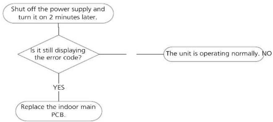
flowchart
graph TD
    A["Shut off the power supply and turn it on 2 minutes later."] --> B{Is it still displaying the error code?}
    B -->|YES| C["Replace the indoor main PCB."]
    B -->|NO| D["The unit is operating normally. NO"]
Remarks:
EEPROM: A read-only memory whose contents can be erased and reprogrammed using a pulsed voltage. The ocation of the EEPROM chip on the indoor PCB is shown in the following image.
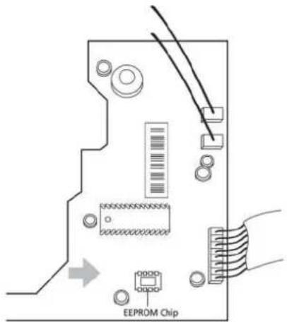
Note: The image is for reference only.
6.2 EH 02 (Zero crossing detection error diagnosis and solution)
Description: When PCB does not receive zero crossing signal feedback for 4 minutes or the zero crossing signal time interval is abnormal.
Recommended parts to prepare:
- Connection wires
- Indoor PCB
Troubleshooting and repair:
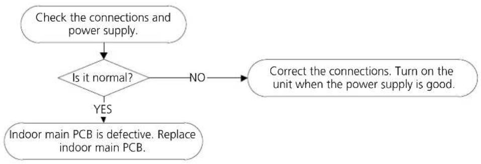
flowchart
graph TD
    A["Check the connections and power supply."] --> B{Is it normal?}
    B -->|NO| C["Correct the connections. Turn on the unit when the power supply is good."]
    B -->|YES| D["Indoor main PCB is defective. Replace indoor main PCB."]
Note: E2 zero crossing detection error is only valid for the unit with AC fan motor, for other models, this error is invalid.
6.3 EH 03/ EC 07 (Fan speed is operating outside of the normal range diagnosis and solution)
Description: When indoor fan speed keeps too low (300 RPM) for certain time, the unit will stop and the LED displays the failure code.
Recommended parts to prepare:
- Connection wires
- Fan assembly
- Fan motor
PCB
Troubleshooting and repair:
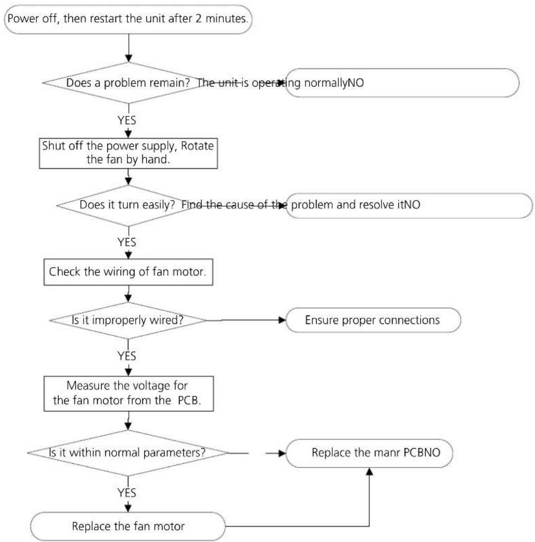
flowchart
graph TD
    A["Power off, then restart the unit after 2 minutes."] --> B{Does a problem remain? The unit is operating normallyNO}
    B -->|YES| C["Shut off the power supply, Rotate the fan by hand."]
    C --> D{Does it turn easily? Find the cause of the problem and resolve itNO}
    D -->|YES| E["Check the wiring of fan motor."]
    D -->|NO| F{Is it improperly wired?}
    E --> F
    F -->|YES| G["Measure the voltage for the fan motor from the PCB."]
    F -->|NO| H["Ensure proper connections"]
    G --> I{Is it within normal parameters?}
    H --> J["Replace the manr PCBNO"]
    I --> K["Replace the fan motor"]
    J --> K
Index:
- Indoor or Outdoor DC Fan Motor(control chip is in fan motor)
Power on and when the unit is in standby, measure the voltage of pin1-pin3, pin4-pin3 n an motor connector. If the value of the voltage is not in the range showing in below table, the PCB must has problems and need to be replaced.
- DC motor voltage input and output voltage: 220-240V\~1
| No. | Color Signal | Voltage | |
| 1 | Red VsIVm 280V~380V | ||
| 2 | ... ... | ||
| 3 | Back GND 0V | ||
| 4 | White Vcc | 14-17.5V | |
| 5 | Yellow Vsp | 0~5.6V | |
| 6 | Blue FG | 14-17.5V |
- DC motor voltage nput and output voltage: 115V\~1
| No. | Color Signal | Voltage | |
| 1 | Red Vs/Vm 140 | V~190V | |
| 2 | .... | .... | |
| 3 | Back GND 0V | ||
| 4 | White Vcc | 14-17.5V | |
| 5 | Yellow Vsp | 0~5.6V | |
| 6 | Blue FG | 14-17.5V | |
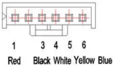
- Outdoor DC Fan Motor (control chip is in outdoor PCB)
Release the UVW connector. Measure the resistance of U-V, U-W, V-W. The resistance is not equal to each other, the fan motor must has problems and need to be replaced. otherwise the PCB must have problems and need to be replaced.
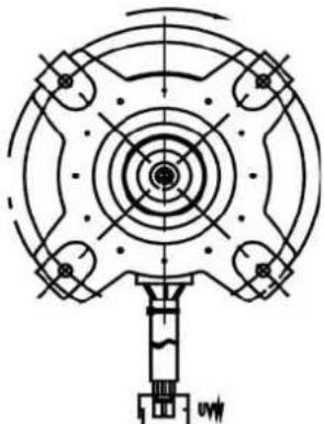
natural_image
Technical line drawing of a mechanical component with concentric circles and mounting holes (no text or symbols)3. Indoor AC Fan Motor
Power on and set the unit running in fan mode at high fan speed. After running for 15 seconds, measure the voltage of p n1 and p n2. If the value of the voltage is less than 100V|208\~240V power supply or 50V(115V power supply), the PCB must has problems and need to be replaced.
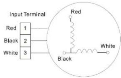
6.4 EH 60/EH 61/EC 52 (Open or short circuit of temperature sensor diagnosis and solution)
Description: If the sampling voltage is lower than 0.06V or higher than 4.94V, the LED displays the failure code.
Recommended parts to prepare:
- Sensors
PCB
- Connection wires
Troubleshooting and repair:
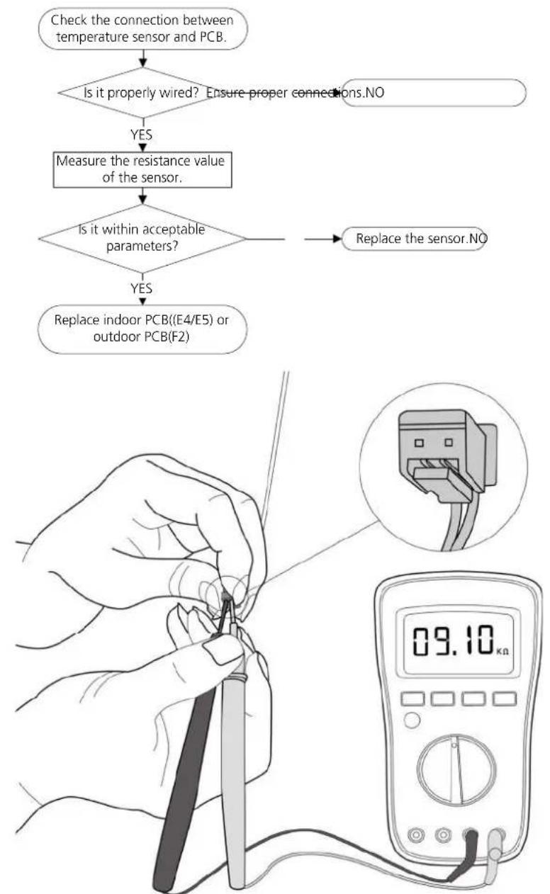
flowchart
graph TD
    A["Check the connection between temperature sensor and PCB."] --> B{Is it properly wired? Ensure proper connections.NO}
    B -->|YES| C["Measure the resistance value of the sensor."]
    C --> D{Is it within acceptable parameters?}
    D -->|YES| E["Replace indoor PCB((E4/E5) or outdoor PCB(F2))"]
    D -->|NO| F["Replace the sensor.NO"]
    E --> G["Digital multimeter displaying 09.10 kn"]
Note: The picture and the value are only for reference, actual condition and specific value may vary.
6.5 EL 0C (Refrigerant leakage detection diagnosis and solution)
Description:
Judging the changes in operating parameters caused by excessive exhaust temperature.
Recommended parts to prepare:
- Compressor
- Capacitor of compressor
- Indoor PCB
- System problems, such as leakage or blockages
- Capacitor of fan motor
- Outdoor fan
Troubleshooting and repair :
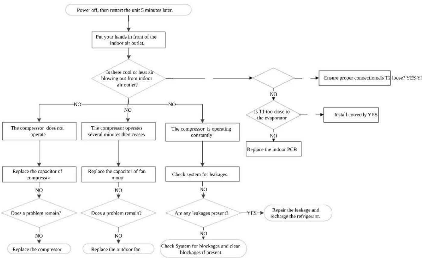
flowchart
graph TD
    A["Power off, then restart the unit 5 minutes later."] --> B["Put your hands in front of the indoor air outlet."]
    B --> C{Is there cool or heat air blowing out from indoor air outlet?}
    C -->|NO| D["The compressor does not operate"]
    C -->|NO| E["The compressor operates several minutes then ceases"]
    C -->|NO| F["The compressor is operating constantly"]
    D --> G["Replace the capacitor of compressor"]
    E --> H["Replace the capacitor of fan motor"]
    F --> I["Check system for leakages."]
    G --> J{Does a problem remain?}
    H --> K{Does a problem remain?}
    I --> L{Are any leakages present?}
    J --> M["Replace the compressor"]
    K --> N["Replace the outdoor fan"]
    L --> O["Check System for blockages and clear blockages if present."]
    M --> P["Repair the leakage and recharge the refrigerant."]
    N --> Q["Check System for blockages and clear blockages if present."]
    C --> R{Is T1 too close to the evaporator}
    R -->|NO| S["Replace the indoor PCB"]
    R -->|NO| T["Ensure proper connections.Is T2 loose? YES Y!"]
    R -->|NO| U["Install correctly YES"]
    S --> V["End"]
    T --> V
    U --> V
6.6 EL 01 (Indoor / outdoor unit communication error diagnosis and solution)
Description: The indoor unit has not received feedback from the outdoor unit for 110 seconds, four consecutive times
Recommended parts to prepare:
- Indoor PCB
- Outdoor PCB
- Reactor
Troubleshooting and repair:
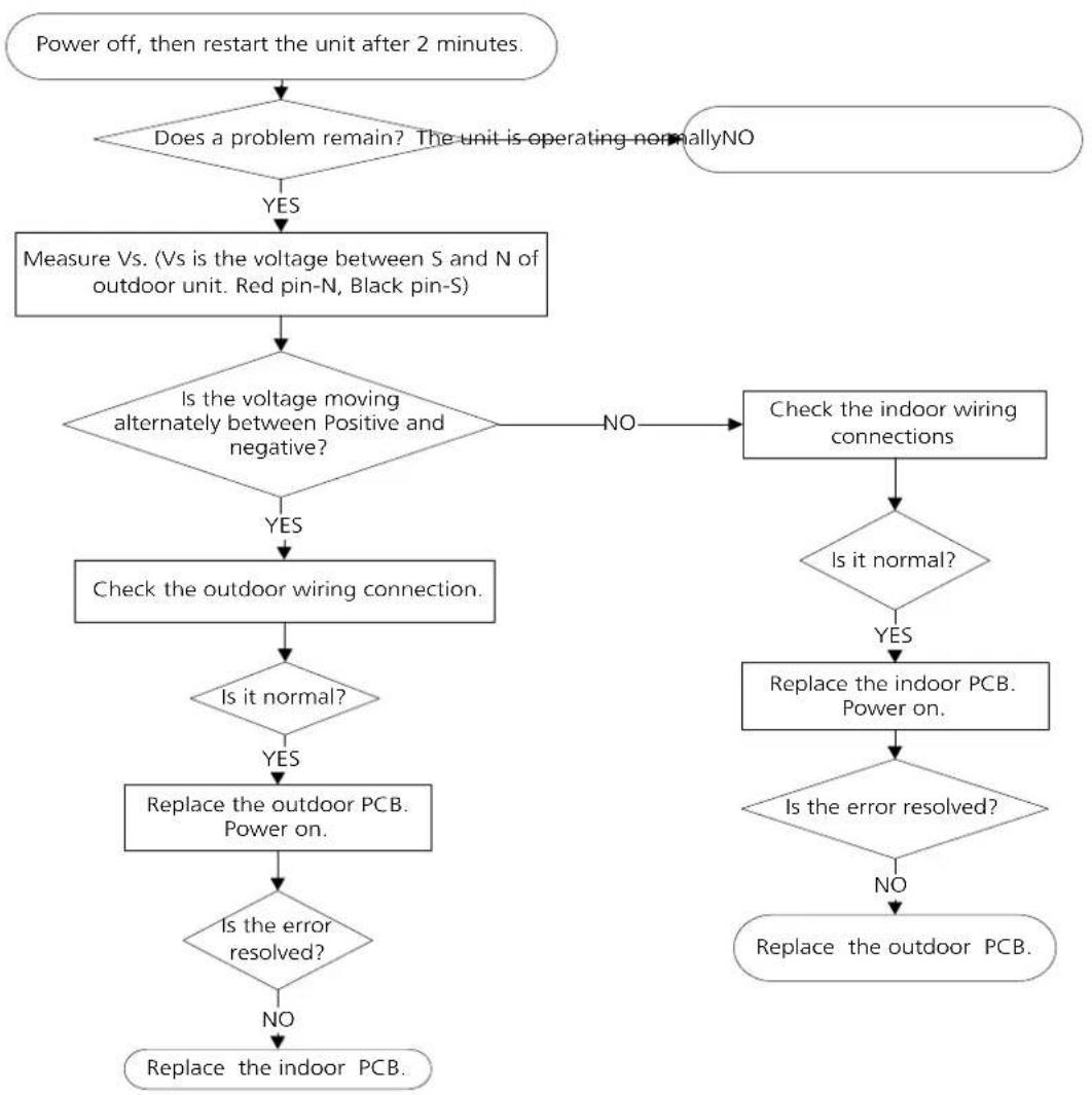
flowchart
graph TD
    A["Power off, then restart the unit after 2 minutes."] --> B{Does a problem remain? The unit is operating normallyNO}
    B -->|YES| C["Measure Vs. (Vs is the voltage between S and N of outdoor unit. Red pin-N, Black pin-S)"]
    C --> D{Is the voltage moving alternately between Positive and negative?}
    D -->|YES| E["Check the outdoor wiring connection."]
    D -->|NO| F["Check the indoor wiring connections"]
    E --> G{Is it normal?}
    G -->|YES| H["Replace the outdoor PCB. Power on."]
    G -->|NO| I["Replace the indoor PCB. Power on."]
    H --> J{Is the error resolved?}
    J -->|YES| K["Replace the outdoor PCB. Power on."]
    J -->|NO| L["Replace the indoor PCB. Power on."]
    K --> M{Is the error resolved?}
    M -->|YES| N["Replace the outdoor PCB. Power on."]
    M -->|NO| O["Replace the indoor PCB. Power on."]
Remarks:
- Use a multimeter to test the DC voltage between 2 portior S or L2 porti and 3 portior N or S porti of outdoor unit. The red pin of multimeter connects with 2 portior S or L2 porti while the back pin is for 3 portior N or S porti. When AC is normal running, the voltage will move alternately between -25V to 25V.
- If the outdoor unit has malfunction, the voltage will move alternately with positive value.
- While if the indoor unit has malfunction, the voltage will be a certain value
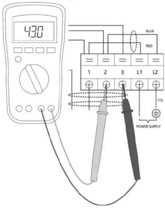
S and N
or
L2 and S
or
2 and 3
Note: The picture and the value are only for reference, actual condition and specific value may vary.
6.7 PC 03 (High pressure protection)
Description: If the current is less than setting value for 4 seconds, AC shuts off and restarts after 3 minutes in cooling mode or after 4 minutes in heating mode. If this happens 8 times, the unit stops and the LED displays the failure code
Recommended parts to prepare:
- System bookages
- Dirty condenser
Troubleshooting and repair:
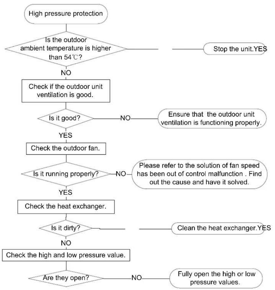
flowchart
graph TD
    A["High pressure protection"] --> B{Is the outdoor ambient temperature is higher than 54°C?}
    B -->|NO| C["Check if the outdoor unit ventilation is good."]
    B -->|Yes| D{Is it good?}
    D -->|NO| E["Ensure that the outdoor unit ventilation is functioning properly."]
    D -->|YES| F["Check the outdoor fan."]
    F --> G{Is it running properly?}
    G -->|NO| H["Please refer to the solution of fan speed has been out of control malfunction . Find out the cause and have it solved."]
    G -->|YES| I["Check the heat exchanger."]
    I --> J{Is it dirty?}
    J -->|NO| K["Check the high and low pressure value."]
    J -->|YES| L["Clean the heat exchanger."]
    L --> M{Are they open?}
    M -->|NO| N["Fully open the high or low pressure values."]
    M -->|YES| O["Stop the unit.YES"]
6.8 EH 0b (Indoor PCB/display board communication error diagnosis and solution)
Description: The display board cannot communicate with the indoor PCB
Recommended parts to prepare:
- Communication wire
- Indoor PCB
- Display board
Troubleshooting and repair:
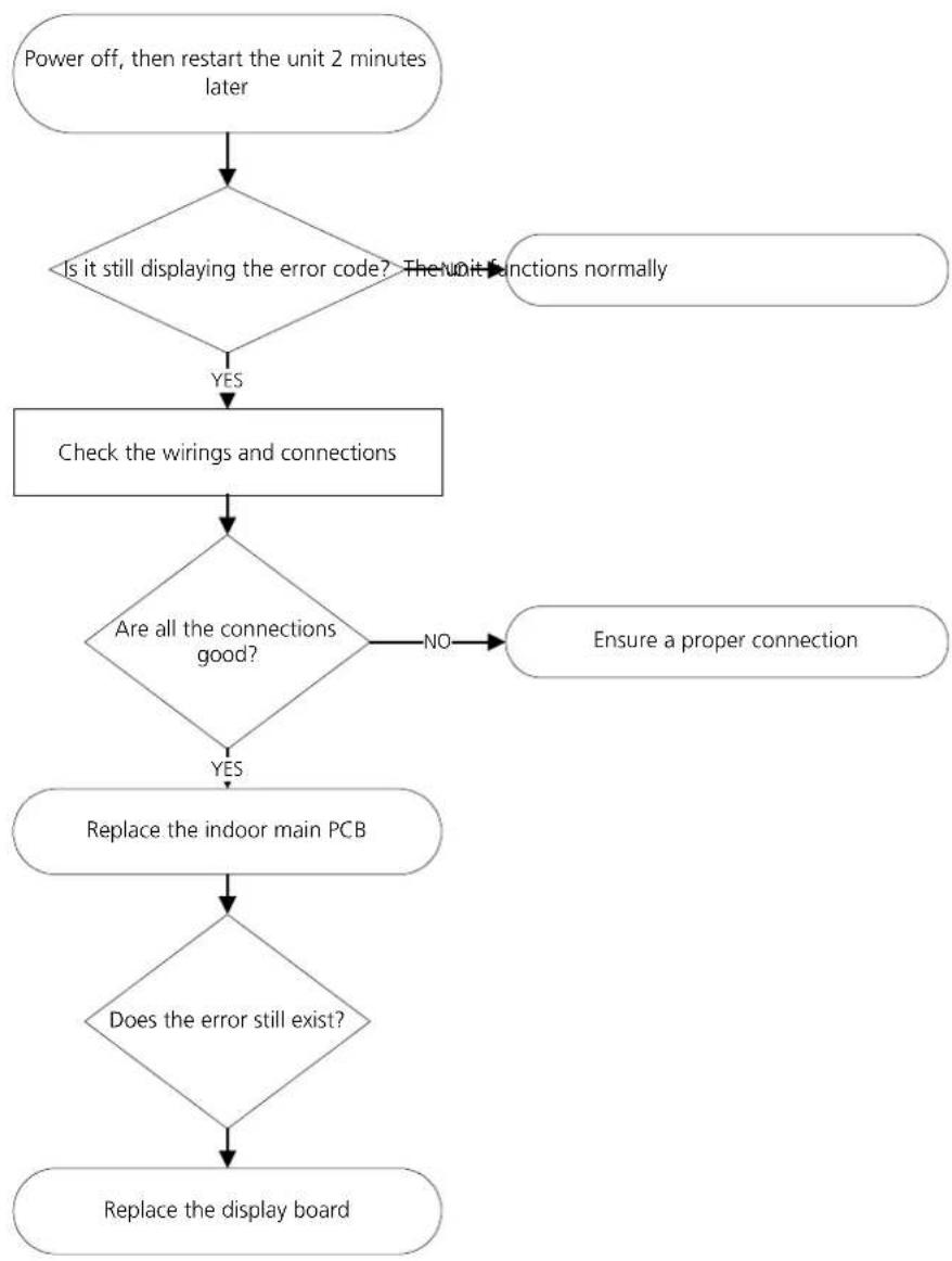
flowchart
graph TD
    A["Power off, then restart the unit 2 minutes later"] --> B{Is it still displaying the error code? The unit functions normally}
    B -->|YES| C["Check the wirings and connections"]
    C --> D{Are all the connections good?}
    D -->|NO| E["Ensure a proper connection"]
    D -->|YES| F["Replace the indoor main PCB"]
    F --> G{Does the error still exist?}
    G --> H["Replace the display board"]
7. Check Procedures
7.1 Temperature Sensor Check

WARNING
Be sure to turn off all power supplies or disconnect all wires to avoid electric shock. Operate after compressor and coil have returned to normal temperature in case of injury.
- Disconnect temperature sensor from PCB Refer to Chapter 5. Indoor Disassembly and Chapter 6. Outdoor Disassembly
- Measure the resistance value of the sensor using a multimeter.
- Check corresponding temperature sensor resistance value table | Refer to Chapter 8. Appendix|
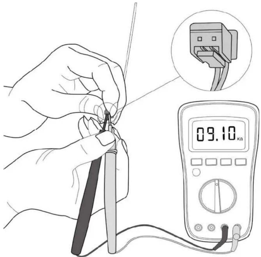
Note: The picture and the value are only for reference, actual condition and specific value may vary.
7.2 Fan Motor Check
- Turn off outdoor unit and disconnect power supply
- Disconnect outdoor fan motor power cord from outdoor PCB
- Measure the resistance value between each windings.
The norma value of different motor show as follows:
| Model | YKFG-20-4-5-21 | YKFG-28-4-3-14 | YKFG-45-4-22-13 |
| Brand Welling | Welling Welling | ||
| Black - Red Man Ω | 442 | 294 | 168 |
| Blue - Black AUX Ω | 450 | 414Ω | 141Ω |
9. Reference Sheet
9-1 Low Refrigerant Pressure Distribution
Cooling chart(R32):
| °F|°C1 | ODU|DB|DU|DB|WB) | 0;17|5 | -15| | 15|9.44| | 45|7.22| | 75|23.89| | 85|29.44| | 95|35| | 105|40.56| | 115|46.11| | 120|48.89| |
| BAR | 70|59 |21 11|15|6 | 6.6 7.4 | 8.2 8.4 8.0 | 8.3 8 8 1 | 0 3 10 8 | ||||||
| 75|63 |23.89|17 22|6 | 8 6 9 8.1 | 8.8 8 8 8 | 5 8.9 9.3 | 10.9 11.4 | |||||||
| 80|67 |26.67|19 44|7 | 2 7 3 8.7 | 9.7 9 5 9 | 1 9.3 9.8 | 11.4 12.1 | |||||||
| 90|73 |32.22|22 78|7 | 9 8 0 9.8 | 10.7 10.5 | 9 7 10.2 | 10.8 12.6 | 13.3 | ||||||
| PS | 70|59 |21 11|15|95 | 96 108 1 | 18 121 11 | 5 119 12 | 8 150 157 | ||||||
| 75|63 |23.89|17 22|9 | 9 101 117 | 128 126 | 122 129 | 35 158 1 | 65 | ||||||
| 80|67 |26.67|19 44|1 | 05 106 12 | 5 141 13 | 8 132 135 | 143 165 | 176 | ||||||
| 90|73 |32.22|22 78|1 | 14 115 14 | 2 155 15 | 2 141 148 | 157 184 | 193 | ||||||
| MPa | 70|59 |21 11|15|0 | 65 0.66 0 | 74 0.82 0 | 84 0 80 | 0 83 0.88 | 1.03 1.08 | |||||
| 75|63 |23.89|17 22|0 | 68 0 69 0 | 81 0 88 | 0 88 0 85 | 0.89 0.93 | 1.09 1.14 | ||||||
| 80|67 |26.67|19 44|0 | 72 0 73 0 | 87 0.97 | 0 95 0 91 | 0.93 0.98 | 1.14 1.21 | ||||||
| 90|73 |32.22|22 78|0 | 79 0 80 0 | 98 1 07 | 1 05 0 97 | 1 02 1 08 | 1.26 1.33 |
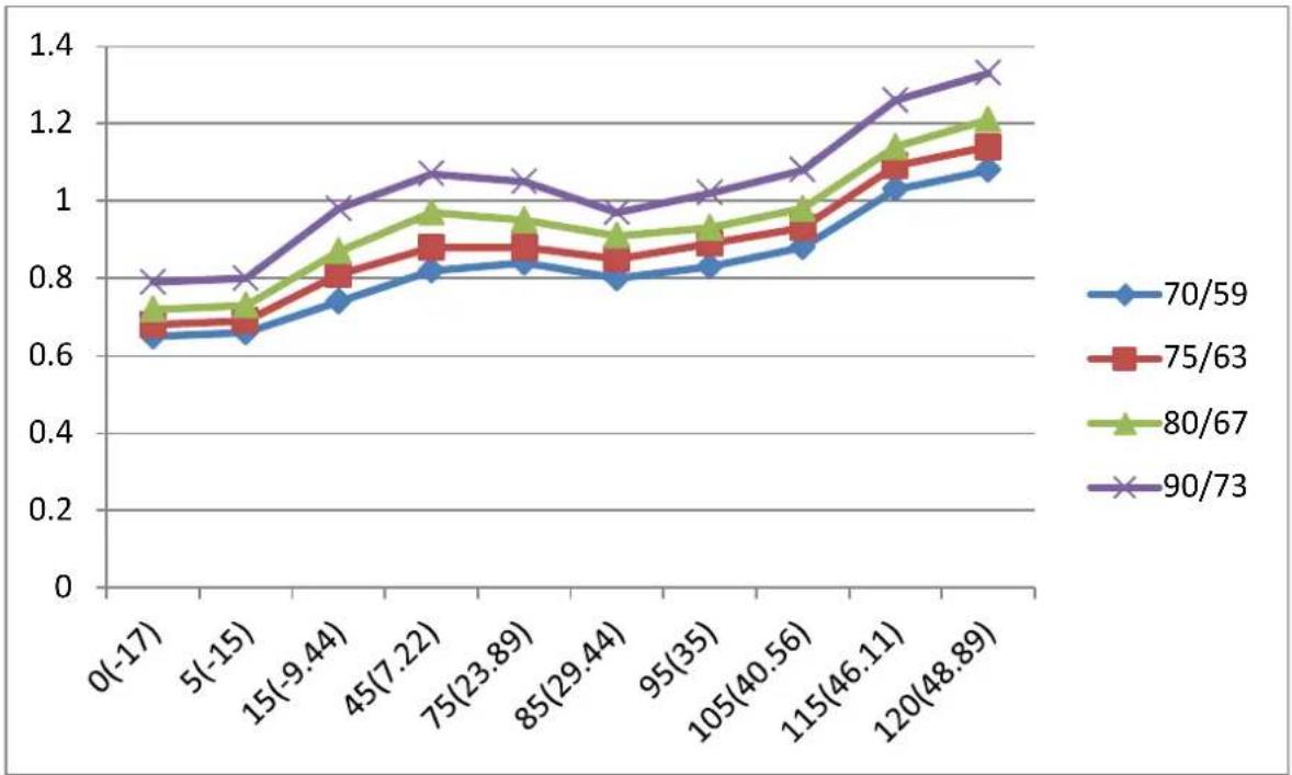
line
| X Value | 70/59 | 75/63 | 80/67 | 90/73 | | ----------- | ------ | ------ | ------ | ------ | | 0(-17) | 0.64 | 0.66 | 0.70 | 0.80 | | 5(-15) | 0.65 | 0.68 | 0.72 | 0.80 | | 15(-9.44) | 0.73 | 0.78 | 0.85 | 0.98 | | 45(7.22) | 0.81 | 0.87 | 0.96 | 1.07 | | 75(23.89) | 0.82 | 0.87 | 0.94 | 1.04 | | 85(29.44) | 0.78 | 0.85 | 0.91 | 0.96 | | 95(35) | 0.82 | 0.87 | 0.92 | 1.02 | | 105(40.56) | 0.87 | 0.91 | 0.96 | 1.07 | | 115(46.11) | 1.01 | 1.07 | 1.14 | 1.26 | | 120(48.89) | 1.07 | 1.14 | 1.21 | 1.33 |Heating chart(R32):
| °F|°C| | ODU|DB|WB; |DU|DB| | 57|53|13.89|11 67| | 47|43|8 33|6 11| | 37|33|2.78|0.56| | 27|23|-2 78|-5| | 17|13|-8.33|-10.56| | 0|-2|-17|-19| | -17|-18|-27|-28| |
| BAR | 55|12.78|30 9 | 29 1 25 8 23 3 | 21 2 18 9 16 8 | |||||
| 65|18.33|33 2 | 30 6 27 1 25 9 | 23 8 20 9 19 4 | ||||||
| 75|23.89|34 5 | 32 1 28 4 26 8 | 25 4 21 9 20 4 | ||||||
| PSI | 55|12.78|448 | 421 374 337 30 | 8 273 244 | |||||
| 65|18.33|480 | 444 394 375 34 | 6 303 282 | ||||||
| 75|23.89|499 | 466 411 389 36 | 9 318 296 | ||||||
| MPa | 55|12.78|3.09 | 2.91 2.58 2 33 | 2.12 1.89 1.68 | |||||
| 65|18.33|3.32 | 3.06 2.71 2 59 | 2.38 2.09 1.94 | ||||||
| 75|23.89|3.45 | 3.21 2.84 2 68 | 2.54 2.19 2 04 |
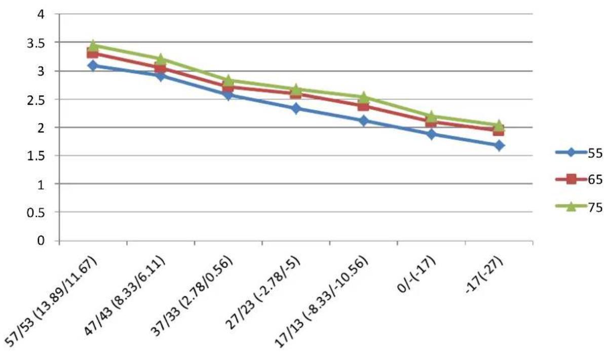
line
| Category | 55 | 65 | 75 | | ------------------ | -------- | -------- | -------- | | 57/53 (13.89/11.67) | 3.1 | 3.3 | 3.4 | | 47/43 (8.33/6.11) | 2.9 | 3.0 | 3.2 | | 37/33 (2.78/0.56) | 2.6 | 2.7 | 2.8 | | 27/23 (-2.78/-5) | 2.3 | 2.6 | 2.7 | | 17/13 (-8.33/-10.56)| 2.1 | 2.4 | 2.5 | | 0/(-17) | 1.9 | 2.1 | 2.2 | | -17(-27) | 1.7 | 1.9 | 2.0 |9-2 Pressure & Capacity mark
Power/Heat
| W | cal/s | kcal/h | Btu/h | HP | kg.m/s | lb.m/s |
| 1 | 0.23885 | 0.85985 | 3.4121 | 0.001341 | 0.10197 | 0.73756 |
| 4.1868 | 1 | 3.6 | 14.286 | 0.0056146 | 0.42693 | 3.088 |
| 1.163 | 0.27778 | 1 | 3.9683 | 0.0015596 | 0.11859 | 0.85778 |
| 0.29307 | 0.06999 | 0.252 | 1 | 3.9302 × 10^-4 | 0.029885 | 0.21616 |
| 745.7 | 178.11 | 641.19 | 2,544.4 | 1 | 76.04 | 550 |
| 9.8067 | 2.3423 | 8.4322 | 33.462 | 0.013151 | 1 | 7.233 |
| 1.3558 | 0.32383 | 1.0658 | 4.6262 | 0.0018182 | 0.13826 | 1 |
9-3 Cleaning /Filter Change
Removing the Air filter
- Lift the front panel of the indoor unit.
- First press the tab on the end of filter to loosen the buckle, lift it up, then pull it towards yourself.
- Now pull the filter out.
- I² your filter has a small air freshening filter, unclip it from the larger filter. Clean this air freshening filter with a hand-held vacuum.
- When dry, re-clip the air freshening filter to the larger filter then slide it back into the indoor unit.
- Close the front panel of the indoor unit
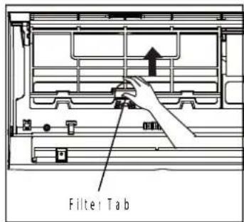
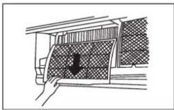
natural_image
Hand holding a grid-patterned panel with a black arrow pointing downward (no text or symbols)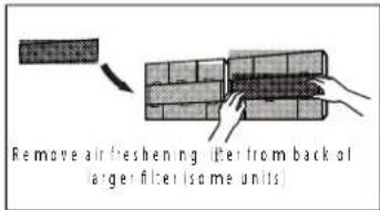
Cleaning the air filter
Washable foam based air filter captures large particles from the air. The filter is cleaned with a vacuum or by hand washing.
Remove the Air filter from the main body.
Clean the Air filter with a vacuum cleaner or soft brush. If dust is too heavy, rinse it with running water.
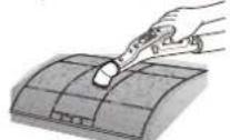
Insert the Air filter back in its original position.
Dry the Air filter in a ventilated area.
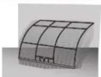
9-4 Installation
9-4-1 Before Installation
Keep the air conditioner outlet and inlet free from its surroundings. In case of installation, keep the symmetry and fix it to prevent vibration. The pipe length shall meet the standard as far as possible.
9-4-2 Installation Procedure
■ Location
Install the product in an area to guarantee the best cooling effect, convenience of piping and electric work, and inexistence of vibration or wind.
■ Wall Drilling
Drill the wall downward in a diameter of 60 to 65mm.
■ Fixing Indoor Unit & Outdoor Unit
Fix the air conditioner indoor unit securely to the wall. Secure the outdoor unit in a suitable position.
■ Pipe Spooling & Connectingt
You shall cut the pipe with a pipe cutter and grind all the burrs of the cut surface. pipe expansion may continue until the pipe surface becomes uneven or torn apart. Be sure to use a torque wrench to tighten pipes or flare nuts. TORQUE REQUIREMENTS
| Outer Diameter of Pipe (mm) | Tightening Torque (N·m) | Flare dimension(B) (mm) | Flare shape |
| ∅ 6.35 (∅ 0.25") | 18~20(180~200kgf.cm) | 8.4~8.7 (0.33~0.34") | 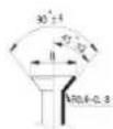 |
| ∅ 9.52 (∅ 0.375") | 32~39(320~390kgf.cm) | 13.2~13.5 (0.52~0.53") | |
| ∅ 12.7 (∅ 0.5") | 49~59(490~590kgf.cm) | 16.2~16.5 (0.64~0.65") | |
| ∅ 16 (∅ 0.63") | 57~71(570~710kgf.cm) | 19.2~19.7 (0.76~0.78") | |
| ∅ 19 (∅ 0.75") | 67~101(670~1010kgf.cm) | 23.2~23.7 (0.91~0.93") |
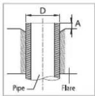
■ Leak Test
Put an inset gas like nitrogen in the outdoor unit pipe and put soap bubbles or other test liquids on the pipe surface for the leak test.
■ Drain Hose Connecting
Install the drain hose downward to drain water naturally. Be sure to pour water into the hose to check if it drains well.
Electric & Earth Work
Electric and earth work shall meet the "Electric Facility Technology Standard" and the "Internal Wire Regulation" of the Electric Business Laws.
■ Inspection & Trial Run
Upon completion of the tests, you shall make a trial run while you explain the main functions of the air conditioner to finish the installation.
9-5-1 Air-Purge Procedure
1) Connect each assembly pipe to the appropriate valve on the outdoor unit and tighten the flare nut.

2) Connect the charging hose of low pressure side of manifold gauge to the packed valve having a service port (3/8" Packed valve) as shown at the figure.

3) Open the valve of the low pressure side of manifold gauge counter-clockwise.

4) Purge the air from the system using vacuum pump for about 30 minutes.
- After that, please recheck that pressure is stabilized.
- Close the valve of the low pressure side of manifold gauge clockwise.
- Remove the hose of the low pressure side of manifold gauge.

5) Set valve cork of both liquid side and gas side of packed valve to the open position.

6) Mount the valve stem nuts to the 2 way and 3 way valve. And mount the service port cap to 3 way valve.

7) Check for gas leakage. - At this time, especially check for gas leakage from the 3 way valve's stem nuts, and from the service port cap.
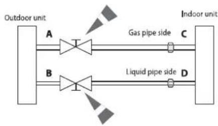
flowchart
graph LR
    A["Outdoor unit"] --> B["A"]
    B --> C["Gas pipe side C"]
    D["Indoor unit"] --> E["D"]
    E --> F["Liquid pipe side D"]
    style A fill:#f9f,stroke:#333
    style B fill:#f9f,stroke:#333
    style C fill:#ccf,stroke:#333
    style D fill:#ccf,stroke:#333
    style E fill:#ccf,stroke:#333
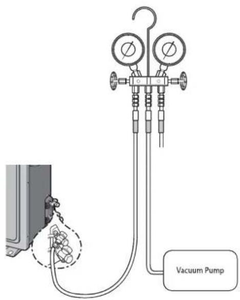
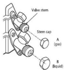
9-5-2 "Pump down" Procedure
Pump down will be carried out when an evaporator is replaced or when the unit is relocated in another area.
1) Remove the caps from the 3 way valve and the 3 way valve.

2) Turn the 3 way valve clockwise to close and connect a pressure gauge (low pressure side) to the service valve, and open the 3 way valve again.

3) Set the unit to cool operation mode. (Check if the compressor is operating.)

4) Turn the 3 way valve clockwise to close.

5) When the pressure gauge indicates "0" turn the 3 way valve clockwise to close.

6) Stop operation of the air conditioner.

7) Close the cap of each valve.
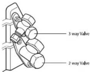

Remarks
Relocation of the air conditioner
• Refer to this procedure when the unit is relocated.
- Carry out the pump down procedure (refer to the details of 'pump down').
- Remove the power cord.
- Disconnect the assembly cable from the indoor and outdoor units.
- Remove the flare nut connecting the indoor unit and the pipe.
- At this time, cover the pipe of the indoor unit and the other pipe using a cap or vinyl plug to avoid foreign material entering.
- Disconnect the pipe connected to the outdoor unit.
At this time, cover the valve of the outdoor unit and the other pipe using a cap or vinyl plug to avoid foreign material entering.
• Make sure you do not bend the connection pipes in the middle and store together with the cables.
- Move the indoor and outdoor units to a new location.
- Remove the mounting plate for the indoor unit and move it to a new location.
| Digit NO | 1 | 2 | 3 | 4 | 5 | 6 | 7 | 8 | 9 | 10 | 11 | 12 | 13 | 14 | |||||
| Product | 용량(K BTU) | YEAR | Type(Ref. inv. ONOFF) | Feature | Design | Series | Color code | Product type | Sub | ||||||||||
| Code | A | B | 1 | 2 | A | G | H | Q | A | W | K | N | S | T | |||||
| AR | RAC | 7 | 7K BTU/H | T: 2020 | S | INV.HP R410A | A | MDS+PM1.0 Filter+PM1.0 Sensor+Wi-Fi | Q | ODMMIDEA | A | 1st MODEL | WK | DA White | / | CBU SET | Thailand(XST)→ ST | ||
| 9 | 9K BTU/H | A: 2021 | V | INV.CO R410A | B | MDS + PM1.0 Filter+Wi-Fi | B | 2nd MODEL | N | CBU IDU | |||||||||
| 12 | 12K BTU/H | B: 2022 | X | INV.HP R32 | C | MDS + Wi-Fi+ Tri-care Filter | C | 3rd MODEL | X | CBU ODU | |||||||||
| 18 | 18K BTU/H | C: 2023 | Y | INV.CO R32 | D | MDS + Wi-Fi | D | 4th MODEL | 1 | CKD SET | |||||||||
| 24 | 24K BTU/H | H | 경숙형HP R32 | E | Wi-Fi+Tri-care Filter | E | 5th MODEL | U | CKD IDU | ||||||||||
| 30 | 30K BTU/H | G | 경숙형CO R32 | F | Wi-Fi | F | 6th MODEL | W | CKD ODU | ||||||||||
| Q | ONOFFHP R410a | G | Tri-care Filter | G | 7th MODEL | 2 | SKD SET | ||||||||||||
| R | ONOFFCO R410a | H | - | Y | SKD IDU | ||||||||||||||
| P | ONOFFHP R22 | Z | SKD ODU | ||||||||||||||||
| C | ONOFFCO R22 | ||||||||||||||||||
SAMSUNG ELECTRONICS
This Service Manual is a property of Samsung Electronics Co., Ltd. Any unauthorized use of Manual can be punished under applicable International and/or domestic law.