50F - Compressor POWERNAIL - Free user manual and instructions
Find the device manual for free 50F POWERNAIL in PDF.

User questions about 50F POWERNAIL
0 question about this device. Answer the ones you know or ask your own.
Ask a new question about this device
Download the instructions for your Compressor in PDF format for free! Find your manual 50F - POWERNAIL and take your electronic device back in hand. On this page are published all the documents necessary for the use of your device. 50F by POWERNAIL.
USER MANUAL 50F POWERNAIL
natural_image
Black-and-white photo of a PowerNAIL® power tool with adjustable foot base, displayed on wooden workbench (no text or symbols visible on the device itself)OPERATION AND MAINTENANCE MANUAL MANUAL DE OPERACION Y DE MANTENIMIENTO MANUEL D'INSTRUCTIONS ET D'ENTRETIEN
WARNING

Read this manual before you use this Powernailer®. Follow all safety warnings and instructions. If you are uncertain about the operation of the nailer, call us directly at 1-800-323-1653 for assistance or contact the closest Powernail Dealer for help. Please retain this information for future reference.
INTRODUCTION
The Model 50F trigger-pull nailer is designed to bring Powernail quality and flooring expertise to a pneumatic nailer. The Model 50F is designed for use with 1-1/4" to 1-3/4", 18 gauge L-Cleat Powernails®. The Model 50F nails from 3/8" to 3/4" flooring through the use of a FLEX adjustable foot assembly that can be adjusted to fit different flooring profiles.
INDEX
| Index...... 2 | Clearing a jam...... 8 |
| Warranty...... 2 | Troubleshooting Chart... 9 |
| Operating the tool...... 4-6 | Schematic / Parts List.. 10-11 |
| FLEX Foot Adjustment...5 | Nail Depth Chart...... 12 |
| Air Supply...... 6 | Phone Support...... 12 |
| Maintenance...... 7 | Web Site...... 12 |
| Safety Labels...... 7 | Powernail Company Info 12 |
| Loading Fasteners......6 |
LIMITED WARRANTY
POVERNAIL® Company, Inc. warrants to its customer, and to the first end-use purchaser of POWERNAIL Model 50F POWERNAILER purchased from an authorized POWERNAIL distributor, that each serialized manufactured Model 50F POWERNAILER by POWERNAIL®, for a period of 12 months from the date of purchase; shall be free of defects in materials and workmanship and will meet POWERNAIL'S specifications in effect at the time of product shipment. POWERNAIL will repair or replace, at its option, any Model 50F POWERNAILER that does not conform to this warranty. Claims must be made no later than fifteen (15) days after the end of the warranty period. POWERNAIL will perform all repair or replacements itself or through its authorized distributors. POWERNAIL is not responsible for shipping, labor or other direct or indirect costs. Damage caused by abuse, misuse, unusual or excessive wear is excluded. Repair or modification of the Products by unauthorized parties will void this warranty. The customer is responsible for returning Products to POWERNAIL for verification of nonconformance. Warranties for Products not manufactured by POWERNAIL are limited to warranties provided to POWERNAIL by the manufacturer of such product that are assignable to customer.
THESE WARRANTIES AND REMEDIES ARE EXCLUSIVE OF ALLOTHERS, EXPRESS OR IMPLIED. THE WARRANTIES OF MERCHANTABILITY AND FITNESS FOR PURPOSE ARE EXPRESSLY EXCLUDED. IN NO EVENT SHALL POWERNAIL'S LIABILITY FOR A WARRANTY CLAIM EXCEED THE PRICE PAID TO POWERNAIL FOR THE NONCONFORMING PRODUCT, REGARDLESS OF THE FORM OR BASIS OF THE CLAIM OR CAUSE OF ACTION.
SAFETY INSTRUCTIONS

When operating this Nailer, the operator and others in the work area should ALWAYS wear approved SAFETY GLASSES, with front and side eye protection. Eye protection will help guard against flying nails and debris, which could cause severe eye injury.
EAR PROTECTION should be used to prevent hearing damage when there are high noise levels in the work area. ALWAYS use ear plugs with a noise reduction rated at 29 db or higher at a construction site.
Do not operate this tool if it does not contain a legible WARNING LABEL.
Noise characteristic values in accordance with ENxx1:
A-weighted single-event sound pressure level at operator's position: LPA, ls94dBA
A-weighted single sound pressure level:LpA,Is,Im89dBA
Vibration characteristic values in accordance with ISO 8662, PART II
Weighted root mean square acceleration 3.2 m/s^2
Always DISCONNECT THE AIR SUPPLY before making any adjustments, repairing, clearing jams or when the Nailer is not in use. Do not use on scaffolding or ladders and disconnect nailer from air supply when transporting between installation areas.
Never attach the female end of a quick disconnect to the Nailer. This will trap air inside the Nailer and permit it to be discharged. Only the unrestricted male connection should be attached to the Nailer.
Nailer requires an air source that can continuously deliver 70 to 120 psi at 3-1/2 cubic feet of air per minute for operation. Normal air pressure should not exceed 120 psi or damage to the Nailer and seals may occur. Excess air pressure can cause the Nailer to explode. Do not continue to use a tool that leaks air or does not function properly. Notify your nearest Powernail representative if your tool continues to experience functional problems.
To prevent fire or explosion, use only regulated compressed air—do not use bottled gases of any kind (no oxygen or combustible gasses) to power this Nailer. Nailer is intended for use installing wood flooring and is not to be used for purposes not specified in the operations manual.
Do not use any nails other than Powernail® Powercleats which are 18 gauge L-cleat nails specifically designed for use in any 18 gauge Powernailer. Powercleat nails are available in lengths of 1-1/4", 1-1/2" and 1-3/4". Contact your Powernail Dealer for the correct Powercleats for the Model 50F.
Use only Powernail replacement parts in the repair or maintenance of this nailer. Parts or repair services are available from the manufacturer or from agents authorized by the manufacturer. Repairs should be carried out only by trained service personnel in the field of fastener driving tools who will observe proper safety controls while performing maintenance. Service personnel should be qualified to assess the safe working condition of fastener driving tools.
Always make sure Nailer is empty of nails before connecting air hose, so as to prevent any accidental discharge from occurring. ONLY CONNECT AIR TO AN UNLOADED NAILER.
Do not depress the trigger when loading. If the fasteners are jammed, disconnect the tool from the air supply before you remove the jammed nails.

Never place any part of the body in the discharge path of the Nailer when air is connected to the Nailer. Never point the tool at yourself or others, even if the tool is not loaded. For safety, keep out of reach of children. Never leave the Nailer unattended while it is connected to an air supply. Never disable, clamp or tape the safety trigger in an activated position.
Do not fire into hard materials or attempt to use on hard or brittle material such as concrete, steel or tile. Before using this tool, carefully check that all parts are working correctly. Do not use the tool if it is not operating correctly, check for causes and adjust as necessary for proper operation. When not in use, the tool should be cleaned, fully assembled and then stored in a dry location. This will extend the life of the tool and reduce any oxidation.
OPERATION
The Model 50F nails down fl ooring from 3/8" to 3/4" using the Powernail FLEX adjustable foot assembly that can be adjusted to fit different fl ooring profi les.
To use the Model 50F, properly position the tool on the flooring plank (See picture below). Pull up and hold the black safety trigger to activate the orange fi ring trigger. The nailer will drive and set the nail at the correct angle.
Note: Modifying or altering the nailer in anyway can potentially cause injury and may void the warranty.
The unique body design allows for different grip angles and has an adjustable exhaust port to redirect nailer exhaust.
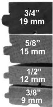
The Model 50F installs tongue and groove flooring from 3/8" to 3/4"
text_image
3/4" 19 mm 5/8" 15 mm 1/2" 12 mm 3/8" 9 mmAdjustable Exhaust
- Directional and adjustable exhaust directs air away from user
Escape ajustable
• Prevents accidental discharge, protecting the user as well as the floor
Anodized Aluminum Magazine
- Model 50F uses both standard and HD 1-1/4", 1-1/2", 1-3/4" 18-Gauge L-Cleats
Adjustable FLEX Foot
- Allows the user to quickly adjust to different plank heights (3/8", 1/2", 5/8", 3/4"). Prevents rocking while stabilizing the tool in the nail pocket.
Pie FLEX ajustable
- Fits today's wide variety of wood profiles, even interlocking plank!
Nariz única
FLEX Foot Adjustment
How to adjust your tool's foot to your floor's thickness:
Use the photos on the right for reference:
1.) First loosen the tool's FLEX foot by turning the lever from right to left/counter clockwise. (See image 1.a)
a.) The FLEX foot should now freely slide up-and-down the magazine.
2.) Using a sample of your fl ooring, slide the FLEX foot back on the channel and set the nose of the stapler securely into the nail pocket (see image 1.b). Important: Orient the board as it is intended to be installed, with the fl oor board's surface facing up.
3.) While keeping the nose of the stapler/nailer in the nail pocket (resting on top of the tongue and against the shoulder) slide the FLEX foot forward until it lies flat at on the flooring surface. (see image 1.c)
4.) Now turn the FLEX foot's adjustment lever from left to right (clockwise) to tighten the foot. (see image 1.d)
5.) Always test fire into a test piece of flooring to ensure the nail is setting correctly.
If your FLEX foot is not tight enough:
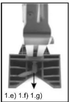
1.) If your tool's foot is not tight enough or if the FLEX foot is not maintaining its "set" position, you may adjust its tightness by pulling OUT on the lever (see image 1.e) and turning it from right to left (see image 1.f). Release the lever (make sure that it reseats) and turn from left to right (see image 1.g). This is a form of ratcheting mechanism and does not require any tools to loosen or tighten.
a.) ***If your Flex Foot needs to be loosened, reverse the process listed above.
2.) If you are experiencing trouble in making this adjustment please visit www.powernail.com/f-series-adjustment to view a helpful demonstration video.
natural_image
Mechanical component diagram showing a rotating shaft and housing (no text or symbols)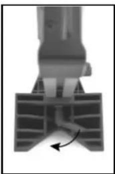
natural_image
Mechanical component diagram showing a rotating shaft and housing (no text or symbols)
natural_image
Mechanical robotic arm with a highlighted component, labeled '1.a)' (no text or symbols on the device itself)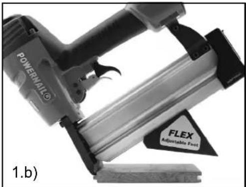
natural_image
Close-up of a power railer with a FLEX adjustable foot tag, no visible text or symbols on the device itself.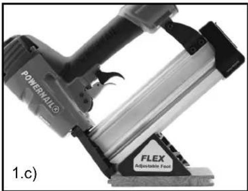
natural_image
Close-up of a Powerwall 3 feed kit with FLEX Adjustable Foot (no visible text or symbols on the device itself)
natural_image
Mechanical robotic arm with a highlighted component, labeled '1.d)' (no text or symbols on the device itself)CONNECTING THE TOOL TO AN AIR SUPPLY
Your air tool is fully assembled when you receive it. Before using it, attach the air line and desired air system accessories. Be sure the air hose is depressurized when installing or removing adapters to the air line. To prevent misfi re, do not connect air to a loaded nailer.
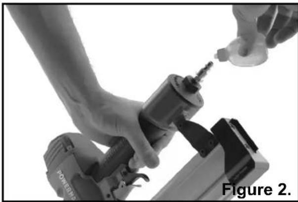
1.) An automatic airline oilier is recommended but oil may be added manually before every operation or after about 8 hours of continuous use.
2.) Place two (2) drops of air-tool oil in the air plug as shown (Figure 2). If you are using an automatic in-line oiler, check and add oil if necessary.
3.) Turn your compressor on and set the compressors pressure regulator to the proper pressure. Normal operating pressure should be adjusted between 70-120 psi based on fastener and wood being used.
4.) Connect the tool to the air supply (Figure 3).
LOADING THE FASTENERS
1.) Insert a full stick of 1-1/4", 1-1/2" or 1-3/4" 18 gauge Powercleats through the slotted Magazine Rear Cover(49) into the Magazine (47) (Figure 4)
2.) Pull back the spring loaded Nail Pusher (39) over the nails until it contacts the last nail and slowly release the Nail Pusher. The nailer is now loaded. (Figure 5)
natural_image
Close-up of hands using a power tool to adjust or install a component, labeled 'Figure 2.' (no text on the tool itself)
text_image
Quick Connector Air Hose Figure 3.
natural_image
Close-up of a mechanical device with a hand holding a clip, labeled 'Figure 4.' (no other text or symbols visible)
natural_image
Close-up of hands operating a mechanical device with a tool, labeled 'Figure 5.' (no text on device or background)MAINTENANCE
REGULAR MAINTENANCE
1.) Frequent, but not excessive, lubrication is required for best performance. Oil added through the airline connection will lubricate internal parts. An automatic airline oilier is recommended but oil may be added manually before every operation or after about 8 hours of continuous use.
Only a few drops of oil at a time are necessary. Too much oil will collect inside the tool and be blown out during the exhaust cycle. ONLY USE PNEUMATIC TOOL OIL. Do not use detergent oil or additives, as these lubricants will cause accelerated wear to the seals in the tool.
2.) Use a small amount of oil on all moving surfaces and pivots.
3.) Dirt and water in the air supply are major causes of pneumatic tool wear. Use a filter/oiler for better performance and longer life. The filter must have adequate flow capacity for the specific application.
4.) Keep tools clean for better and safer performance. Use nonflammable cleaning solutions only if necessary. CAUTION: Soaking the tool may damage O-rings and other tool parts.
- Read and understand tool labels and manual. Failure to follow warnings could result in death or serious injury.
- Operators and others in work area must wear safety glasses with side shields. 3. Keep fingers away from trigger when not driving fasteners to avoid accidental firing. 4. Choice of triggering method is important. Check manual for triggering options. 5. Never point tool at yourself or others in work area. 6. Never use oxygen or other bottled gasses. Explosion may occur.
- Do not exceed 120 PSI.


POWERNAIL®
Model 50F
18 GA L-Cleats
Use Genuine Powernail
1-1/4" to 1-3/4"
18 Gauge L-Powercleats


Made in Taiwan
CLEARING A JAM
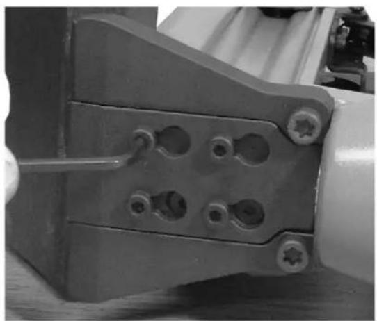
Disassembly: (See Figure 7.)
1) NOTE: Do not remove the four M4 screws (80).
2) Loosen the 4 M4 screws (78) with a 3mm allen wrench.
3) Slide the gate plate down until it is free from the nose..
6) Lift the gate plate (72) off.
5) Inspect and clear any debris from the drive blade (27) and its path.
Reassembly:
1) Install the gate plate over the four M4 screws (72).
2) Slide the gate plate upwards as far as it go.
3) Tighten the four M4 screws.
4) Unit is ready for funtional testing.
natural_image
Close-up of a mechanical component with multiple holes and a tool inserted (no visible text or symbols)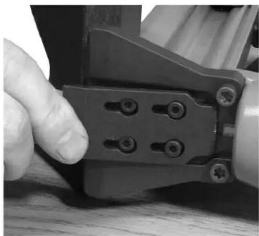
natural_image
Close-up of a hand using a crimping tool to adjust or install a mechanical component (no visible text or symbols)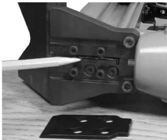
natural_image
Close-up of a mechanical assembly with a tool inserted, showing components like bolts and a metal bracket (no visible text or symbols)TROUBLE SHOOTING CHART
Here are some common issues that may occur during use.
If the nailer is not working as it should, stop using the tool immediately and resolve the issue before continuing.
| PROBLEM POSSIBLE CAUSE SOLUTION | |||
| 1 | Air leaking at Trigger area | 1. O-ring (34) in trigger valve is damaged.2. Trigger valve head (34) is damaged.3. Trigger valve stem, seal or O-ring (34) is damaged. | 1. Check and replace O-ring.2. Check and replace trigger valve head.3. Check and replace trigger valve stem, seal or O-ring. |
| 2 | Air leaking between body and drive guider | Damaged bumper (21). Check and replace bumper. | |
| 3 | Air leaking between body and cylinder cap | 1. Screw loose (5).2. Damaged gasket (22). | 1. Tighten screws.2. Check and replace gasket. |
| 4 | Blade driving fastener too deeply | 1. Worn bumper (21).2. Air pressure is too high | 1. Replace bumper.2. Adjust the air pressure. |
| 5 | Runs slowly or has loss of power | 1. Insuffi cient oil.2. Insuffi cient air supply.3. Broken spring in cylinder cap (9).4. Exhaust port (3) in cylinder cap is blocked | 1. Lubricate as instructed2. Check air supply.3. Replace spring.4. Replace damaged internal parts. |
| 6 | Tool skips a fastener | 1. Worn bumper (21) or damaged spring (38).2. Dirt in gate (49).3. Inadequate airfl ow to tool.4. Worn or dry O-ring (17) on piston.5. Cylinder cap seal leaking (22). | 1. Replace bumper or pusher spring.2. Clean drive channel of front plate.3. Check hose and compressor fi ttings.4. Replace O-ring or lubricate.5. Replace seal. |
| 7 | Fasteners are jammed(see page 8) | 1. Joint guider is worn (25).2. Fasteners are wrong size or damaged.3. Magazine or front plate screws are loose (45).4. Blade (15) in piston assembly is damaged. | 1. Replace joint guider.2. Use the recommended and undamaged fasteners.3. Tighten screws.4. Replace piston assembly. |
| 8 | Tool will not drive down tight | 1. Worn blade in piston assembly.2. Lack of power.3. Slow cycling and loss of power. | 1. Replace piston assembly.2. Adjust to adequate air pressure.3. Check cylinder cap spring for broken coils or reduced length.Check if exhaust port of cylinder cap is restricted. |
MODEL 50F PARTS LIST
| ITEM DESCRIPTION Avail. QTY PART # | ||||
| 1 UM. | HD.BOLT | S 1 09-50F001 | ||
| 2 FLAT | WASHER | S 1 09-50F002 | ||
| 3 EXH | AUST COVER,METAL | S 1 09-50F003 | ||
| 4 SEAL | S 1 09-50F004 | |||
| 5 HEX | .SOC.HD.BOLT+SW | $ 4 | 09-50F005 | |
| 6 CAP | S 1 09-50F006 | |||
| 7 SPACER | S 1 09-50F007 | |||
| 8 PISTON STOPPER** | S 1 09-50F008 | |||
| 9 SPRING** | S 1 09-50F009 | |||
| 10 | O RING** | KIT | 1 | - |
| 11 | PISTON HEAD VALVE | S | 1 | 09-50F011 |
| 12 | O RING** | KIT | 2 | - |
| 13 | SEAL | S 1 | 09-50F013 | |
| 14 | O RING** | KIT | 1 | - |
| 15 | PISTON/DRIVE BLADE | N/A | 1 | - |
| 15A | DRIVE BLADE ASSEMBLY W/ (#14 O-RING) | S 1 09-50F015A | ||
| 16 | CYLINDER | S 1 09-50F016 | ||
| 17 | O RING** | KIT | 2 | - |
| 18 | O RING** | KIT | 1 | - |
| 19 | COLLAR | S 1 09-50F019 | ||
| 20 | O RING | KIT | 1 | - |
| 21 | BUMPER | S 1 09-50F021 | ||
| 22 | CYLINDER CAP SEAL | S | 1 | 09-50F022 |
| 23 | STEPPED PIN | S 2 09-50F023 | ||
| 24 | BODY | N/A | 1 | - |
| 25 | JOINT GUIDE | S 1 09-50F025 | ||
| 26 | O RING** | S 2 09-50F026 | ||
| 27 | STEPPED PIN | S 1 09-50F027 | ||
| 28 | TOR. SPRING | S 1 09-50F028 | ||
| 29 | TRIGGER | S 1 09-50F029 | ||
| 30 | E RING | S 1 09-50F030 | ||
| 31 | O RING** | S 1 09-50F031 | ||
| 32 | END CAP | S 1 09-50F032 | ||
| ITEM DESCRIPTION Avail. QTY PART # | ||||
| 35 | SPRING | S | 1 | 09-50F035 |
| 36 | BUMP FIRE TRIGGER | S | 1 | 09-50F036 |
| 37 | PUSHER GUIDE | S | 1 | 09-50F037 |
| 38 | SPRING | S | 1 | 09-50F038 |
| 39 | PUSHER | S | 1 | 09-50F039 |
| 40 | FLAT HD SELF SCREW | S | 1 | 09-50F040 |
| 41A | PUSHER ASSEMBLY | S | 1 | 09-50F041A |
| 42 | HEX.SOC.HD.BOLT | S | 7 | 09-50F042 |
| 43 | NOSE COVER / GATE PLATE | S | 109-50F043 | |
| 44 | HEX.SOC.HD.BOLT | S | 2 | 09-50F044 |
| 45 | FLAT. HD.BOLT | S | 3 | 09-50F045 |
| 46 | NOSE / GATE | S | 1 | 09-50F046 |
| 47 | MAGAZINE | S | 1 | 09-50F047 |
| 48 | FLEX FOOT LOCK NUT | S | 1 | 09-50F048 |
| 49 | MAGAZINE REAR COVER | S | 109-50F049 | |
| 50 | HEX. SOC. HD. BOLT | S | 2 | 09-50F050 |
| 51 | BRACKET | S | 1 | 09-50F051 |
| 52 | FLEX FOOT BASE | S | 1 | 09-50F052 |
| 53 | NO-MAR PAD | S | 1 | 09-50F053 |
| 54 | FLAT WASHER | S | 1 | 09-50F054 |
| 55 | FLEX FOOT ADJUST-MENT LEVER | S | 109-50F055 | |
| SEAL KIT | S | 1 09-50F99SK | ||
KEY: S=Sold Separately, N/A= Not available separately, KIT=Sold as part of a Kit,
MODEL 50F SCHEMATIC

text_image
Exploded view diagram of a mechanical assembly with numbered components and exploded viewsPOWERCLEATS LENGTH DETERMINATION CHART
This chart will assist you in determining the proper length of Powercleats to use for various thicknesses of flooring. Approximate vertical penetration of the Powercleat under the hardwood floor is shown for each application. This is only a guide. Results should be tested in the fi eld before proceeding.
Nail Penetration for 3/4" Subfl ooring.
1-3/4" PowerCleats (18 Gauge)
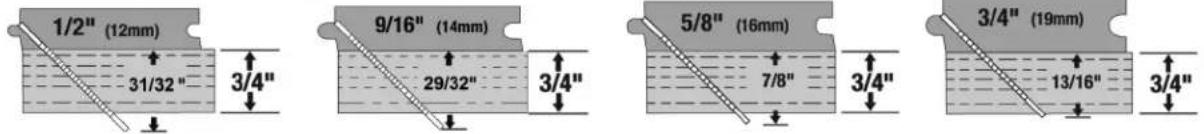
text_image
1/2" (12mm) 31/32" 3/4" 9/16" (14mm) 29/32" 3/4" 5/8" (16mm) 7/8" 3/4" 3/4" (19mm) 13/16" 3/4"1-1/2" PowerCleats (18 Gauge)

text_image
3/8" (10mm) 7/8" 3/4" 1/2" (12mm) 13/16" 3/4" 9/16" (14mm) 3/4" 3/4" 5/8" (16mm) 11/16" 3/4"1-1/4" PowerCleats (18 Gauge)

text_image
3/8" (10mm) 11/16" 3/4" 1/2" (12mm) 5/8" 3/4" 9/16" (14mm) 9/16" 3/4" 5/8" (16mm) 1/2" 3/4"18 GA HD POWERCLEATS®

text_image
POWERNAIL® +5 Series of 1,000 3-24" (50 mm) 16.0x Hardwood Flooring L-Class Hits -3 Surfaces in 1 MM 5-14" (50 mm) 6.0x your plastic devels have -5 Scales in 1 MM 5-14" (50 mm) denna in flutes 18.0x power in middle rows MODSLS AIR SERVICE - MIN SERIES - SIM SERIES POWERNAIL® 1/2" 1/3" (49.3 M/M) 1/3" (49.3 M/M) 18 GA Hardwood Flooring L-Class Hits HDQHEAD HOPHEAD HOPHEAD 1.175-10-5 CITY 5,MM - QTY 5,000 - CTE 5,MM 1¼" (2.0,MM) 5 BLOOD BY: 3,000 POWERNAIL® 10 Hardwood Flooring L-Class Hits HDQHEAD 1¾" 18 POWERNAIL® 1/4" HDQHEAD1 ^1/4 " 5 Pack
(5 x 1,000 Cleats)
Part #: L125185
1½" 5 Pack
(5 x 1,000 Cleats)
Part #: L150185
1 ^3/_4 " 5 Pack
(5 x 1,000 Cleats)
Part #: L175185
©Powernail Company 2017
POWERNAIL COMPANY, INC.
1300 Rose Road, Lake Zurich, IL 60047 US
Phone: 1-800-323-1653 or 847-847-3000
www.powernail.com