1890U - Compressor POWERNAIL - Free user manual and instructions
Find the device manual for free 1890U POWERNAIL in PDF.

| Brand | POWERNAIL |
| Model | 1890U |
| Product Type | Air Compressor |
| Power Supply | Electric, 230V / 50Hz |
| Power Consumption | 1500W |
| Max Pressure | 8 bar |
| Tank Capacity | 24 liters |
| Air Flow | 180 L/min |
| Dimensions (L x W x H) | 40 x 30 x 30 cm |
| Weight | 15 kg |
| Noise Level | 80 dB |
| Material | Steel tank, aluminum pump |
| Features | Oilless pump, automatic shut-off, pressure gauge, safety valve |
| Intended Use | Pneumatic tools, tire inflation, painting |
| Maintenance | Drain tank daily, clean air filter monthly |
| Protection Class | IP20 |
| Accessories Included | Air hose, tire chuck, blow gun |
| Warranty | 2 years |
Frequently Asked Questions - 1890U POWERNAIL
User questions about 1890U POWERNAIL
0 question about this device. Answer the ones you know or ask your own.
Ask a new question about this device
Download the instructions for your Compressor in PDF format for free! Find your manual 1890U - POWERNAIL and take your electronic device back in hand. On this page are published all the documents necessary for the use of your device. 1890U by POWERNAIL.
USER MANUAL 1890U POWERNAIL
natural_image
Black and white photo of a PowerNAR Nivel presser tool with metal railings (no visible text or symbols)OPERATION AND MAINTENANCE MANUAL MANUAL DE OPERACION Y DE MANTENIMIENTO MANUEL D'INSTRUCTIONS ET D'ENTRETIEN
WARNING

Read this manual before you use this Powernailer®. Follow all safety warnings and instructions. If you are uncertain about the operation of the nailer, call us directly at 1-800-323-1653 for assistance or contact the closest Powernail Dealer for help. Please retain this information for future reference.
REV 15.08.07
INTRODUCTION
The 1890U PowerStapler® is a trigger-pull stapler designed to bring Powernail quality and flooring expertise to a pneumatic stapler. The 1890U is designed for use with 1/4" crown, 18 GA staples from 7/8" to 1-1/2" in length.
INDEX
Index......
Warranty....2
Safety Instructions...... 3
Operating the tool.... 4-6
Air Supply.... 5
Loading fasteners...... 6
Clearing a jam.... 7
2 Safety Labels...... 7
Troubleshooting Chart...... 9
Parts List.... 10
Schematic.... 11
Phone Support...... 12
Web Site.... 12
Powernail Company Info..... 12
LIMITED WARRANTY
POVERNAIL® Company, Inc. warrants to its customer, and to the first end-use purchaser of POWERNAIL 1890U PowerStapler purchased from an authorized POWERNAIL distributor, that each serialized manufactured 1890U PowerStapler by POWERNAIL®, for a period of 12 months from the date of purchase; shall be free of defects in materials and workmanship and will meet POWERNAIL'S specifications in effect at the time of product shipment. POWERNAIL will repair or replace, at its option, any 1890U PowerStapler that does not conform to this warranty. Claims must be made no later than fifteen (15) days after the end of the warranty period. POWERNAIL will perform all repair or replacements itself or through its authorized contractors. POWERNAIL is not responsible for shipping, labor or other direct or indirect costs. Damage caused by abuse, misuse, unusual or excessive wear is excluded. Repair or modification of the Products by unauthorized parties will void this warranty. The customer is responsible for returning Products to POWERNAIL for verification of nonconformance. Warranties for Products not manufactured by POWERNAIL are limited to warranties provided to POWERNAIL by the manufacturer of such product that are assignable to customer.
THESE WARRANTIES AND REMEDIES ARE EXCLUSIVE OF ALL OTHERS, EXPRESS OR IMPLIED. THE WARRANTIES OF MERCHANTABILITY AND FITNESS FOR PURPOSE ARE EXPRESSLY EXCLUDED. IN NO EVENT SHALL POWERNAIL'S LIABILITY FOR A WARRANTY CLAIM EXCEED THE PRICE PAID TO POWERNAIL FOR THE NONCONFORMING PRODUCT, REGARDLESS OF THE FORM OR BASIS OF THE CLAIM OR CAUSE OF ACTION.
SAFETY INSTRUCTIONS

When operating this Nailer, the operator and others in the work area should ALWAYS wear approved SAFETY GLASSES, with front and side eye protection. Eye protection will help guard against flying nails and debris, which could cause severe eye injury.

EAR PROTECTION should be used to prevent hearing damage when there are high noise levels in the work area. ALWAYS use ear plugs with a noise reduction rated at 29 db or higher at a construction site.
Noise characteristic values in accordance with ENxx1:
A-weighted single-event sound pressure level at operator's position: LPA, Is94dBA
A-weighted single sound pressure level:LpA,Is,Im89dBA
Vibration characteristic values in accordance with ISO 8662, PART II
Weighted root mean square acceleration 3.2m/s ^4
Always DISCONNECT THE AIR SUPPLY before making any adjustments, repairing, clearing jams or when the Nailer is not in use. Do not use on scaffolding or ladders and disconnect nailer from air supply when transporting between installation areas.
Never attach the female end of a quick disconnect to the Nailer. This will trap air inside the Nailer and permit it to be discharged. Only the unrestricted male connection should be attached to the Nailer.
Nailer requires an air source that can continuously deliver 70 to 100 psi at 3-1/2 cubic feet of air per minute for operation.
Normal air pressure should not exceed 100 psi or damage to the Nailer and seals may occur. Excess air pressure can cause the Nailer to explode.
To prevent fire or explosion, use only regulated compressed air—do not use bottled gases of any kind (no oxygen or combustible gasses) to power this Nailer.
Nailer is intended for use installing wood flooring and is not to be used for purposes not specified in the operations manual.
Do not use any nails other than Powernail® Powercleats which are 20 gage L-cleat nails specifically designed for use in any 20 gage Powernailer. Powercleat nails are available in lengths of 1" and 1-1/4". Contact your Powernail Dealer for the correct Powercleats for the Model 2000.
Use only Powernail replacement parts in the repair or maintenance of this nailer. Parts or repair services are available from the manufacturer or from agents authorized by the manufacturer. Repairs should be carried out only by trained service personnel in the field of fastener driving tools who will observe proper safety controls while performing maintenance. Service personnel should be qualified to assess the safe working condition of fastener driving tools.
Always make sure Nailer is empty of nails before connecting air hose, so as to prevent any accidental discharge from occurring. ONLY CONNECT AIR TO AN UNLOADED NAILER.
Do not depress the trigger when loading. If the fasteners are jammed, disconnect the tool from the air supply before you remove the jammed nails.

Never place any part of the body in the discharge path of the Nailer when air is connected to the Nailer. Never point the tool at yourself or others, even if the tool is not loaded. For safety, keep out of reach of children. Never leave the Nailer unattended while it is connected to an air supply.
Do not fire into hard materials or attempt to use on hard or brittle material such as concrete, steel
or tile. Before using this tool, carefully check that all parts are working correctly. Do not use the tool if it is not operating correctly, check for causes and adjust as necessary for proper operation. When not in use, the tool should be cleaned, fully assembled and then stored in a dry location. This will extend the life of the tool and reduce any oxidation.
OPERATION
The Model 1890U is designed for use with 18 gauge, 1/4" crown staples in lengths from 7/8" to 1-1/2".
APPLICATIONS: Carpet and Carpet Pad Installation, Home Insulation Installation
*Only use tool for its intended purposes. Drive fasteners into work surfaces only; never into materials too hard to penetrate.
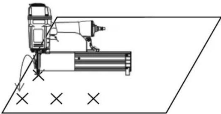
Single-fi re Procedure
- Set the nailer to the work surface with the nose pressed down to release the safety.
- Squeeze the trigger once for single-fi re operation.

natural_image
Technical line drawing of a fastener with a mounted cylindrical component, shown in two orthogonal views (no text or symbols)“Bump-fi re” Procedure
- First squeeze and hold the trigger in the fire position.
- Then push nailer-nose to the surface in the exact spot you wish to nail. The nailer will fire each time the nailer nose is pushed to the work surface when you hold the trigger in the fire position.
natural_image
Technical line drawing of a mechanical assembly with no visible text or symbolsOPERATION, continued...
CONNECTING THE TOOL TO AN AIR SUPPLY
Your air tool is fully assembled when you receive it. Before using it, attach the air line and desired air system accessories. Be sure the air hose is depressurized when installing or removing adapters to the air line. To prevent misfi re, do not connect air to a loaded nailer.
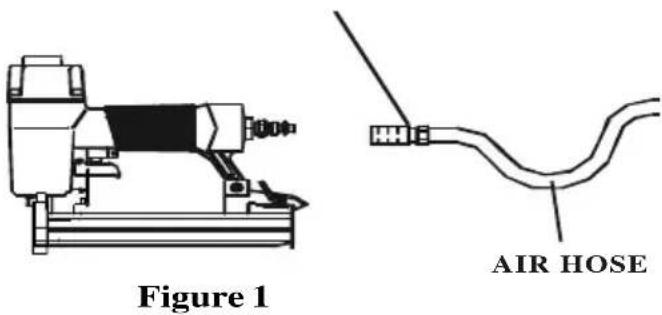
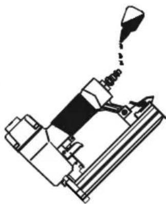
- An automatic airline oilier is recommended but oil may be added manually before every operation or after about 1 hour of continuous use.
- Place two (2) drops of air-tool oil into the air plug at the rear of the nailer. If you are using an automatic in-line oiler, check and add oil if necessary.
- Turn your compressor on and set the compressors pressure regulator to the proper pressure for the size and type of fastener being used. Normal operating pressure should be adjusted between 70-100 psi based on fastener and wood being used.
- Connect the tool to the air supply (Figure 2).
natural_image
Technical line drawing of a mechanical assembly with no visible text or symbolsFigure 2
OPERATING TIPS
Before using this tool, carefully check that all parts are working correctly. Do not use the tool if it is not operating correctly, check for causes and adjust as necessary for proper operation.
Secure your work. Use clamps or a vise to hold your work project in place. It is safer than using your hands and it frees both hands to operate tool.
Do not drive fasteners on top of other fasteners or with tool at too steep of an angle; the fasteners may ricochet and injure someone.
Do not drive fasteners too close to the edge of the work surface. The work piece is likely to split and the fastener could fly free or ricochet and injure someone.
Do not fire into hard materials or attempt to use on hard or brittle materials such as concrete, steel or tile.
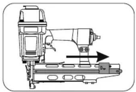
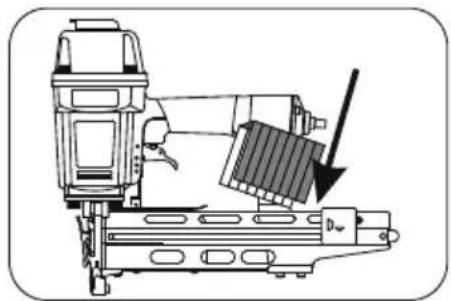
LOADING STAPLES
-
Disconnect air supply.
-
Pull back on staple pusher in the magazine unit until it locks over the spring loaded stopper.
natural_image
Technical line drawing of a mechanical assembly with no visible text or symbols- Load a clip of staples over the top of the staple channel.
natural_image
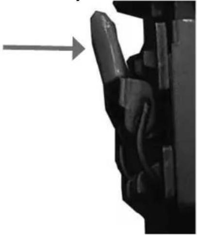
Technical line drawing of a mechanical assembly with an arrow indicating a component (no text or symbols present)-
Release the staple pusher from the spring loaded stopper and gently allow it to move forward to engage the fasteners in the magazine.
-
Connect air supply to the tool.
CLEARING JAMS
- Disconnect air supply.
- Pull the release lever to unlatch magazine cover and slide it to the rear
- Use the release lever to remove the nose-cover assembly.
natural_image
Close-up of a mechanical component with a curved handle and arrow indicating direction (no text or symbols)- Inspect and clear the driveblade path of any material or debris.

text_image
Driving Blade Drive Blade Path- Read and understand operating manual before using.
- Operator and all the by-standers must wear ANSI approved safety glasses, ear and head protections.
- Never use oxygen or other fl ammable gases. Only choose clean dry regulated compressed air below 100 PSI pressure.
- Remove finger from trigger while not operating.
- Never trip over the hose. Make sure all connections are tight.
- Disconnect the tool from air supply before clearing jams, serviceing, adjusting or during non-operation.
- Don't point tool at people or animals while operating.
TROUBLE SHOOTING CHART
Here are some common issues that may occur during use.
If the nailer is not working as it should, stop using the tool immediately and resolve the issue before continuing.
| PROBLEM POSSIBLE CAUSE SOLUTION | |||
| 1 | Air leaking at Trigger valve area | 1. Damaged O-rings in trigger valve housing 1. Replace O-rings and check the operation of safety yoke mechanism | |
| 2 | Air leaking between housing and nose | 1. Loose screws in housing 1. Tighten screws | |
| 3 | Air leaking between housing and cap assembly | 1. Loose screws2. Damaged seal. | 1. Tighten screws.2. Replace seal. |
| 4 | Tool skips driving fastner | 1. Worn bumper.2. Dirt in nose.3. Dirt or damage prevents fasteners from moving freely in magazine.4. Inadequate air flow.5. Worn O-ring on piston or lack of lubrication.6 Damaged O-rings on trigger valve.7. Air leaks.8. Air leakage due to worn cap seal. | 1. Replace bumper2. Clean nose.3. Clean magazine and inspect and repair damage.4. Check fitting, hose and air pressure.5. Replace O-rings and lubrication.6. Replace O-rings.7. Tighten screws and fittings.8. Replace seal. |
| 5 | Weak drive | 1. Tool not lubricated.2. Broken spring in cap assembly.3. Exhaust port in cap is blocked. | 1. Lubrication.2. Replace spring.3. Clean or replace damaged internal parts. |
| 6 | Tool jams | 1. Worn or damaged nose.2. Damaged driver.3. Incorrect size of fastners.4. Bent fasteners.5. Magazine or nose screws are loose. | 1. Replace nose.2. Replace driver.3. Use recommended fasteners.4. Replace with new fasteners.5. Tighten screws. |
| 7 | Tool does not fire | 1. Fasteners jammed in magazine or discharge area.2. Piston shaft is damaged.3. Air pressure too low. | 1. Inspect and clean magazine.2. Replace piston shaft.3. Check/increase air pressure. |
MODEL 1890U PARTS LIST
| ITEM | DESCRIPTION Req PART # | ||
| 2 UM HD Bolt 1 n/a | |||
| 3 Flat Washer 1 n/a | |||
| 4 Seal 1 n/a | |||
| 5 Exhaust Cover 1 n/a | |||
| 6 Cap 1 n/a | |||
| 7 Seal 1 n/a | |||
| 8 Spring 1 n/a | |||
| 9 O Ring 1 09-18U009 | |||
| 10 Head Valve | 1 09-18U010 | ||
| 11 O-Ring 1 09-18U011 | |||
| 12 Cap Gasket 1 09-18U012 | |||
| 13 Hex Soc HD Bolt+SW | 4 n/a | ||
| 14 Drive Blade | 1 n/a | ||
| 14A Drive Blade Asm. w/O-Ring 1 | 09-18U014A | ||
| 15 C-Ring 1 09-18U015 | |||
| 16 Collar | 1 n/a | ||
| 17 C-Ring 1 09-18U017 | |||
| 18 Cylinder | 1 09-18U018 | ||
| 19 C-Ring 1 09-18U019 | |||
| 20 C-Ring 1 09-18U020 | |||
| 21 Bumper | 1 09-18U021 | ||
| 22 Stepped Pin | 1 n/a | ||
| 23 Joint Guide | 1 09-18U023 | ||
| 24 C-Ring 1 09-18U024 | |||
| 25 Body | 1 n/a | ||
| 26 Hex Soc HD Bolt 1 09-18U026 | |||
| 27 Lock Nut | 1 09-18U027 | ||
| 28 C-Ring 1 n/a | |||
| 29 Rear Cover | 1 n/a | ||
| 30 Air Plug | 1 n/a | ||
| 31 Trigger Valve Asm | 1 n/a | ||
| 32 Trigger Assembly | 1 n/a | ||
| 33 Trigger Spring | 1 n/a | ||
| 34 Guide Safety Lever | 1 n/a | ||
| 35 Safety | 1 09-18U035 | ||
| 36 Rubber Safety Pad | 1 09-18U036 | ||
| ITEM | DESCRIPTION Req PART # | ||
| 37 | Hex Soc HD Bolt+SW | 09-18U037 | |
| 38 | Plate | n/a | |
| 39 | Anchor | n/a | |
| 40 | Gate | 09-18U040 | |
| 41 | Locknut | n/a | |
| 42 | Fixed Magazine | n/a | |
| 43 | Hex Soc HD Bolt | 09-18U043 | |
| 44 | Bracket | n/a | |
| 45 | E-Clip | 09-18U045 | |
| 46 | DetentSpring | 09-18U046 | |
| 47 | Stopper | 09-18U047 | |
| 48 | Stepped Pin | n/a | |
| 49 | Pusher | 09-18U049 | |
| 50 | E-Clip | n/a | |
| 51 | Pusher Spring | 09-18U051 | |
| 52 | Roller | n/a | |
| 53 | Hex Soc HD Bolt | 09-18U053 | |
| 54 | Rolled Pin | n/a | |
| 55A | Nose Cover Assembly | 09-18U055A | |
| 56 | Driver Guide Cover | n/a | |
| 57 | Latch | n/a | |
| 58 | Rolled Pin | n/a | |
| 59 | Rubber Release Pad | 09-18U059 |
MODEL 1890U SCHEMATIC
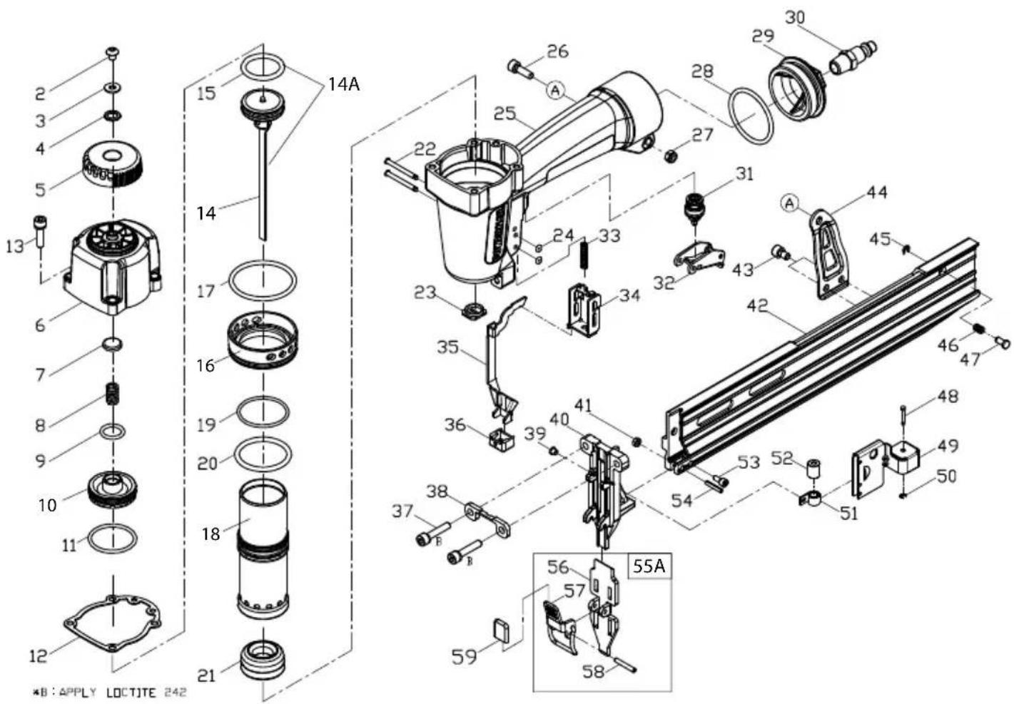
text_image
2 3 4 5 13 6 7 8 9 10 11 12 14A 15 14 17 16 19 20 18 21 35 36 39 40 41 32 34 33 22 23 24 25 26 27 28 29 30 31 44 45 46 47 48 49 50 51 52 53 54 55A 56 57 58 59 *B : APPLY LOCTOTE 242POWERNAIL COMPANY, INC.
1300 Rose Road, Lake Zurich, IL 60047 US
Phone: 1-800-323-1653 or 847-847-3000
www.powernail.com